1
6641-22810
WeOS
RedFox
Industrial Rack
S E R I E S
Industrial Routing Switch
www.westermo.com
© Westermo Teleindustri AB
User Guide
Software tools
Related software tools are available in the folder software tools under
technical support on the Westermo website.
License Information
This device contains public available software which is under the GPL license.
For more information see legal.pdf included with all firmware releases.
This product includes software developed by the OpenSSL Project for use in the
OpenSSL Toolkit. http://www.openssl.org
Legal information
The contents of this document are provided “as is”. Except as required by applicable
law, no warranties of any kind, either express or implied, including, but not limited to,
the implied warranties of merchantability and fitness for a particular purpose, are made
in relation to the accuracy and reliability or contents of this document. Westermo
reserves the right to revise this document or withdraw it at any time without prior
notice.
Under no circumstances shall Westermo be responsible for any loss of data or income
or any special, incidental, and consequential or indirect damages howsoever caused.
More information about Westermo can be found at the following Internet address:
http://www.westermo.com
2
6641-22810
Safety
!
Before installation:
Read this manual completely and gather all information on the unit. Make sure
that you understand it fully. Check that your application does not exceed the safe
operating specifications for this unit.
This unit should only be installed by qualified personnel.
This unit should be built-in to an apparatus cabinet, or similar, where access is
restricted to service personnel only.
The power supply wiring must be sufficiently fused, and if necessary it must be
possible to disconnect manually from the power supply. Ensure compliance to
national installation regulations.
This unit uses convection cooling. To avoid obstructing the airflow around the unit,
follow the spacing recommendations (see Cooling section).
Before powering-up, a protective earthing conductor must be connected to the
protective earthing terminal and have a cross-sectional area of at least 1.5 mm².
!
Before mounting, using or removing this unit:
Prevent access to hazardous voltage by disconnecting the unit from power supply.
Warning! Do not open connected unit. Hazardous voltage may occur within this
unit when connected to power supply.
!
Class 1 Laser Product
Do not look directly into fibre optical fibre port or any connected fibre although
this unit is designed to meet the Class 1 Laser regulations.
Care recommendations
Follow the care recommendations below to maintain full operation of unit and to fulfil
the warranty obligations.
This unit must not be operating with removed covers or lids.
Do not attempt to disassemble the unit. There are no user serviceable parts inside.
Do not drop, knock or shake the unit, rough handling above the specification may cause
damage to internal circuit boards.
Do not use harsh chemicals, cleaning solvents or strong detergents to clean the unit.
Do not paint the unit. Paint can clog the unit and prevent proper operation.
Do not expose the unit to any kind of liquids (rain, beverages, etc). The unit is not waterproof. Keep the unit within the specified humidity levels.
Do not use or store the unit in dusty, dirty areas, connectors as well as other mechanical
part may be damaged.
If the unit is not working properly, contact the place of purchase, nearest Westermo distributor office or Westermo Tech support.
Fibre connectors are supplied with plugs to avoid contamination inside the optical port.
As soon as no optical fibre is mounted on the connector, e.g. for storage, service or
transportation, the plug should be applied.
Warning:
When this unit is operated at an ambient temperature above 53°C, the External Surface
of Equipment may exceed Touch Temperature Limit according to EN/IEC/UL 60950-1.
To reduce the risk of fire, use on No. 26 AWG or larger telecommunication line cord.
6641-22810
3
Note. Fibre Optic Handling
Fibre optic equipment needs special treatment. It is very sensitive to dust and dirt.
If the fibre will be disconnected from the unit the protective hood on the transmitter/
receiver must be connected. The protective hood must be kept on during transportation.
The fibre optic cable must also be handle the same way.
If these recommendations are not followed the warranty might be jeopardized.
Cleaning of the optical connectors
In the event of contamination, the optical connectors should only be cleaned by the use
of recommended cleaning fluids and correct cleaning equipment.
Recommended cleaning fluids:
• Methyl-, ethyl-, isopropyl- or isobutyl-alcohol
• Hexane
• Naphtha
Maintenance
No maintenance is required, as long as the unit is used as intended within the specified
conditions.
4
6641-22810
Agency approvals and standards compliance
Westermo
article number
3641-4005
3641-4015
3641-4025
3641-4035
Denomination
Type
Approval / compliance
RFI-219-F4G-T7GDC
RFI-219-F4G-T7GAC
RFI-227-F4G-T7GDC
EMC
EN 50121-4, Railway applications – Electromagnetic compatibility – Emission and immunity of the signalling and
telecommunications apparatus"
EN 55022, Information technology equipment – Radio
disturbance characteristics – Limits and methods of measurement
EN 55024, Information technology equipment – Immunity
characteristics Limits and methods of measurement
EN 61000-6-1, Electromagnetic compatibility – Immunity
for residential environments
EN 61000-6-2, Electromagnetic compatibility – Immunity
for industrial environments
EN 61000-6-4, Electromagnetic compatibility – Emission
for industrial environments
FCC Part 15 Class A
RFI-227-F4G-T7GAC
FCC Part 15.105
Notice:
This equipment has been tested and found to comply with the limits for a Class A
digital device, pursuant to Part 15 of the FCC Rules. These limits are designed to
provide reasonable protection against harmful interference when the equipment is
operated in a commercial environment. This equipment generates, uses, and can
radiate radio frequency energy and, if not installed and used in accordance with the
instruction manual, may cause harmful interference to radio communications.
Operation of this equipment in a residential area is likely to cause harmful interference
in which case the user will be required to correct the interference at his own expense.
EN 55022 Notice:
This is a class A product. In a domestic environment this product may cause radio
interference in which case the user may be required to take adequate measures.
6641-22810
5
Safety control drawing
Position Direction/
description
Input/output values
1
In/out / BI_DA+
2
In/out / BI_DA–
3
In/out / BI_DB+
4
In/out / BI_DC+
5
In/out / BI_DC–
6
In/out / BI_DB–
7
In/out / BI_DD+
8
In/out / BI_DD–
1
Out / VBUS
Shield
Functional earth
2
In/out / D–
3
In/out / D+
4
GND
Per port:
U = ± 1 V (4V/us)
I = ± 20 mA
Data rate:
10/100/1000 Mbit/s
Position Direction/
description
Galvanically isolated via signal transformers and
capacitively isolated to GND/Functional earth
through a 2kV 1000pF capacitor.
See user manual for proven transient protection.
Shield
Position Direction/
description
Position Direction/
description
DO+
IO / Status +
Input/Output values
Uin = 60 VDC max
DO-
IO / Status –
Iin = 80 mA max
DI+
IO / Digital in +
Uin = 60 VDC max
DI-
IO / Digital in –
Iin = 2.9 mA max
DC Power supply
In / +DC2
In / COM
In / COM
Functional earth
Output values
1
In / VBUS
2
In/out / D–
3
In/out / D+
4
Not connected
5
Functional earth
U = 5 VDC max
I = 100 mA max
Direction/ Input values
description
Uin = (16 – 60) VDC
Iin = 2.0 A@16 VDC
PIn = 31.5 W@16 VDC
In / P
+DC1
In / N
+DC2
In / NC
COM
COM
DC
Degree of protection:
IP 40
Ambient temperature:
–40°C to +70°C.
6
Uout = 5 VDC max
Iout = 500 mA max
AC Power supply
Direction/ Input values
description
In / +DC1
Output values
Uin = (90 – 264) VAC
Iin = 350 mA@115 VAC
In /
6641-22810
Safety control drawing
8
4
7
3
6
2
5
1
Position Direction* / description
1
In/out / TD+
2
In/out / TD–
3
In/out / RD+
4
Not connected
5
Not connected
6
In/out / RD–
7
Not connected
8
Not connected
Shield
Functional earth
Input/output values
Per port:
U = ± 1 V (4V/us)
I = ± 20 mA
Data rate:
10/100 Mbit/s
10/100 Base-TX
Galvanically isolated via signal transformers and capacitively
isolated to functional earth through a 2kV 1000pF capacitor.
See user manual for proven transient protection.
8
4
7
3
6
2
5
1
Position Direction* / description Input/output values
Rx
In / Receive port
Tx
Out / Transmit port
Max 5 dBm
Position Direction* / description Input/output values
1
In/out / BI_DA+
2
In/out / BI_DA–
3
In/out / BI_DB+
4
In/out / BI_DC+
5
In/out / BI_DC–
6
In/out / BI_DB–
7
In/out / BI_DD+
8
In/out / BI_DD–
Shield
Functional earth
Per port:
U = ± 1 V (4V/us)
I = ± 20 mA
Data rate:
100/1000 Mbit/s
1000 Base-T
1000 Base-X
Galvanically isolated via signal transformers and capacitively
isolated to functional earth through a 2kV 1000pF
capacitor.
See user manual for proven transient protection.
* Direction relative this unit!
6641-22810
7
Declaration of Conformity
Westermo Teleindustri AB
Declaration of conformity
The manufacturer
Westermo Teleindustri AB
SE-640 40 Stora Sundby, Sweden
Herewith declares that the product(s)
Type of product
Article number
Models
Industrial Ethernet Switch
for 19 inch Rack mounting
3641-4025
3641-4005
3641-4035
3641-4015
RFIR-227-F4G-T7G-DC
RFIR-219-F4G-T7G-DC
RFIR-227-F4G-T7G-AC
RFIR-219-F4G-T7G-AC
is in conformity with the following EC directive(s).
No
Short name
2004/108/EC
2011/65/EU
Electromagnetic Compatibility (EMC)
Restriction of the use of certain hazardous substances in electrical and electronic
equipment (RoHS)
References of standards applied for this EC declaration of conformity.
No
Title
Issue
EN 50121-4
Railway applications – Electromagnetic compatibility – Emission
and immunity of the signalling and telecommunications
apparatus
Information technology equipment – Radio disturbance
characteristics – Limits and methods of measurement
Information technology equipment – Immunity characteristics
Limits and methods of measurement
Electromagnetic compatibility – Immunity for residential
environments
Electromagnetic compatibility – Immunity for industrial
environments
Electromagnetic compatibility – Emission for industrial
environments
Technical documentation for the assessment of electrical and
electronic products with respect to the restriction of hazardous
substances
2006
EN 55022
EN 55024
EN 61000-6-1
EN 61000-6-2
EN 61000-6-4
EN 50581
The last two digits of the year in which the CE marking was affixed:
2010
2010
2007
2005
+ C1: 2005
2007
+A1:2011
2012
14
Pierre Öberg
Technical Manager
09th September 2014
8
Postadress/Postal address
Tel.
Telefax
Postgiro
Bankgiro
Org.nr/
Corp. identity number
Registered office
S-640 40 Stora Sundby
Sweden
016-428000
Int+46 16428000
016-428001
Int+46 16428001
52 72 79-4
5671-5550
556361-2604
Eskilstuna
6641-22810
Type tests and environmental conditions
Phenomena
ESD
Test
EN 61000-4-2
RF field AM modulated
Fast transient
IEC 61000-4-3
EN 61000-4-4
Surge
EN 61000-4-5
RF conducted
EN 61000-4-6
Power frequency
magnetic field
Pulse magnetic field
Radiated emission
EN 61000-4-8
Conducted emission
EN 61000-4-9
CISPR 16-2-3
ANSI C63.4
(FCC part 15)
EN 55022
FCC part 15
Dielectric strength
Temperature
EN 60950
EN 60068-2-1
EN 60068-2-2
Description
Enclosure contact
Enclosure air
Enclosure
Signal ports
Power ports
Signal ports
Power ports
Signal ports
Power ports
Enclosure
Test levels
± 6 kV
± 8 kV
20 V/m 80% AM (1 kHz), 80 – 2700 MHz
± 2 kV
± 2 kV
± 2 kV line to earth, ± 1 kV line to line
± 2 kV line to earth, ± 2 kV line to line
(AC models)
± 2 kV line to earth, ± 1 kV line to line
(DC models)
10 V 80% AM (1 kHz), 0.15 – 80 MHz
10 V 80% AM (1 kHz), 0.15 – 80 MHz
300 A/m 0, 16.7, 50, 60 Hz
Enclosure
Enclosure
Enclosure
300 A/m
Class A
Class B, 30 – 6500 MHz
AC and DC power
ports
Telecommunication
ports Class B
AC and DC power
ports
Signal port to other
isolated ports
Power port to other
isolated ports
Operating
Class B
Humidity
EN 60068-2-27
Altitude
Service life
Vibration
IEC 60068-2-6
Storage & Transport
Maximum surface
temperature
Operating
Storage & Transport
Operating
Operating
Operating
Shock
IEC 60068-2-27
Operating
Enclosure
UL 94
Aluminium / Zink
6641-22810
Class B
1.5 kVrms 50 Hz 1 min
1.5 kVrms 50 Hz 1 min
-40 to +70ºC (DC models)
-40 to +55ºC (AC models)
-40 to +85ºC (all models)
135°C (temperature class T4)
5 to 95% relative humidity
5 to 95% relative humidity
2 000 m / 70 kPa
10 years
7.5 mm, 5 – 8 Hz
2 g, 8 – 500 Hz
(19" rack mounting according to IEC 60297,
DIN 41494)
15 g, 11 ms
(19" rack mounting according to IEC 60297,
DIN 41494)
Flammability class V-0 (all models)
9
Description
The RFIR (RedFox Industrial Rack) is a high performance layer 3 industrial Ethernet
switch designed for high network traffic applications. Various port configurations are
available that can be further customized with SFP transceivers. RFIR is powered by the
Westermo WeOS network operating system.
RFIR is designed for 19” cabinet according to ETSI standard making it suitable for use in
control room networks as well as for cabi¬nets installed along railway trackside or maritime installations. RFIR is designed to run efficiently from an AC or DC power supply, the
unit is also equipped with configurable I/O fault contact that make it ideal for easy installation and monitoring in industrial applications.
RedFox Industrial Rack models
Westermo
article number
Denomination
3641-4005
RFIR-219-F4G-T7GDC
3641-4015
RFIR-219-F4G-T7GAC
3641-4025
RFIR-219-F4G-T7GDC
3641-4035
RFIR-219-F4G-T7GAC
10
Description
8 x 10/100 Mbit/s, Ethernet TX, RJ-45
7 x 10/100/1000 Mbit/s, Gigabit Ethernet TX, RJ-45
4 x 100/1000 Mbit/s, pluggable connections
transceivers supported, Ethernet FX or TX SFP
DC power supply
8 x 10/100 Mbit/s, Ethernet TX, RJ-45
7 x 10/100/1000 Mbit/s, Gigabit Ethernet TX, RJ-45
4 x 100/1000 Mbit/s, pluggable connections
transceivers supported, Ethernet FX or TX SFP
AC power supply
16 x 10/100 Mbit/s, Ethernet TX, RJ-45
7 x 10/100/1000 Mbit/s, Gigabit Ethernet TX, RJ-45
4 x 100/1000 Mbit/s, pluggable connections
transceivers supported, Ethernet FX or TX SFP
DC power supply
16 x 10/100 Mbit/s, Ethernet TX, RJ-45
7 x 10/100/1000 Mbit/s, Gigabit Ethernet TX, RJ-45
4 x 100/1000 Mbit/s, pluggable connections
transceivers supported, Ethernet FX or TX SFP
AC power supply
6641-22810
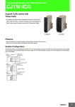
Housing
Description
The RedFox Industrial Rack (RFIR) is designed for installation in 19” rack solutions
according to ETSI standard with a shallow depth of 240 mm. RFIR can also be wall
mounted as an installation option.
Port number RFIR-219-F4G-T7G DC or AC
Port number RFIR-227-F4G-T7G DC or AC
REVISIONS
Rev
Description
Designer
Approved
Date
43
480
462
469
© 2014 WestermoR&D All rights reserved
235
240
411
18
466
Material/Notes
Notes
Denomination
®
RFIR-119-F4G-T7G-AC-ABBCT
Tolerance
Designer
PWM
Drawing No.
Approved
±1mm
Date
Scale
Sheet
1:2 1(1)
Status
3649-0164-UD-00-04 Preliminary
Specification
Dimension W x H x D
466 x 258 x 43 mm
18,35 x 10,16 x 1,66"
Weight
3.8 kg
Degree of protection
IP40 according to EN 60529
Cooling
Convection
Mounting
19" rack or wall-mounted
6641-22810
11
Interface specifications
I/O
Console
port
USB
SFP slot, 100/1000 Mbit/s FX or
10/10/1000 Mbit/s TX ports
10/100/1000 Mbit/s
TX ports
10/100 Mbit/s TX ports
Power
Protective earth
Power interface specifications
DC power
1
4-position
Product marking
Direction
Description
No. 1
+DC1
Input
Supply voltage input DC1
No. 2
+DC2
Input
Supply voltage input DC2
No. 3
-COM
Input
Common
No. 4
-COM
Input
Common
4-position
Product marking
Direction
Description
No. 1
P
Input
Power
No. 2
N
Input
Neutral
No. 3
NC
Input
No connection
Input
Funtional earth
2
3
4
AC power
2
1
3
4
No. 4
12
6641-22810
Power
Rated voltage
AC models
115 to 230 VAC
DC models
20 to 48 VDC
AC models
90 to 264 VAC
DC models
16 to 60 VDC
RFIR-219-F4G-T7G-DC
1120mA @ 24 VDC
450mA @ 48 VDC
RFIR-227-F4G-T7G-DC
1250mA @ 24 VDC
550mA @ 48 VDC
RFIR-219-F4G-T7G-AC
350mA @ 115 VAC 60Hz
210mA @ 230 VAC 50 Hz
RFIR-227-F4G-T7G-AC
380mA @ 115 VAC 60Hz
240mA @ 230 VAC 50Hz
DC models
25mA2 @ 24 VDC
165mA2 @ 48 VDC
AC models
75mA2 @ 115 VAC
340mA2 @ 230 VAC
Startup current*
All models
2x nominal current
Rated frequency
AC models
50/60 Hz
DC models
DC
AC models
Not applicable
DC models
Reverse polarity protected
AC models
No
DC models
Yes
Operating voltage
Maximum nominal current
consumption
Inrush current
Polarity
Redundant power input
Isolation to
All other
Connection
Connector size
Detachable screw terminal
All models
Shielded cable
0.2 – 2.5 mm2 (AWG 24
– 12)
Not required
* External supply current capability for proper start-up
6641-22810
13
Console
Connection to console port
The console port can be used to connect to the CLI (Command Line
Interface). The console connector is a micro USB cable that connects to
a FTDI FT232R USB to serial converter internally. For drivers please see
www.ftdichip.com and download the appropriate VCP driver.
Console
Electrical specification
USB 2.0 device interface
Data rate
High speed 480mbit/s
Circuit type
SE LV
Maximum supply current
100 mA
Isolation to
All other except USB
Galvanic connection to
USB
Connection
USB Micro-B connector in device mode
USB
USB
Electrical specification
Data rate
Circuit type
Maximum supply current
Isolation to
Connection
Conductive housing
14
USB 2.0 host interface
High speed 480mbit/s
SELV
500 mA
All other except Console
USB receptacle connector type A
Yes
6641-22810
Network ports
Slot 1
Slot 2*
RFIR-219-F4G-T7G DC and AC
Slot 1
1
10/100/1000 Mbit/s, TX port
2
10/100/1000 Mbit/s, TX port
3
10/100/1000 Mbit/s, TX port
Slot 2
4
SFP slot
5
10/100/1000 Mbit/s, TX port
6
SFP slot
7
10/100/1000 Mbit/s, TX port
8
SFP slot
9
10/100/1000 Mbit/s, TX port
10
SFP slot
11
10/100/1000 Mbit/s, TX port
Slot 3
12
10/100 Mbit/s, TX port
13
10/100 Mbit/s, TX port
14
10/100 Mbit/s, TX port
15
10/100 Mbit/s, TX port
16
10/100 Mbit/s, TX port
17
10/100 Mbit/s, TX port
18
10/100 Mbit/s, TX port
19
10/100 Mbit/s, TX port
* Network ports at slot 2 and slot 3 differ
between the different RFIR models. Slot 4
is only available in model RFIR-227-F4GT7G DC and AC.
6641-22810
Slot 3*
Slot 4*
RFIR-227-F4G-T7G DC and AC
Slot 1
1
10/100/1000 Mbit/s, TX port
2
10/100/1000 Mbit/s, TX port
3
10/100/1000 Mbit/s, TX port
Slot 2
4
10/100 Mbit/s, TX port
5
10/100 Mbit/s, TX port
6
10/100 Mbit/s, TX port
7
10/100 Mbit/s, TX port
8
10/100 Mbit/s, TX port
9
10/100 Mbit/s, TX port
10
10/100 Mbit/s, TX port
11
10/100 Mbit/s, TX port
Slot 3
12
SFP slot
13
10/100/1000 Mbit/s, TX port
14
SFP slot
15
10/100/1000 Mbit/s, TX port
16
SFP slot
17
10/100/1000 Mbit/s, TX port
18
SFP slot
19
10/100/1000 Mbit/s, TX port
Slot 4
20
10/100 Mbit/s, TX port
21
10/100 Mbit/s, TX port
22
10/100 Mbit/s, TX port
23
10/100 Mbit/s, TX port
24
10/100 Mbit/s, TX port
25
10/100 Mbit/s, TX port
26
10/100 Mbit/s, TX port
27
10/100 Mbit/s, TX port
15
10/100/1000 Mbit/s, TX ports
Ethernet TX
Electrical specification
Data rate
Duplex
Circuit type
IEEE std 802.3. 2005 Edition
10 Mbit/s, 100 Mbit/s, 1000 Mbit/s, manual or auto
Full or half, manual or auto
TNV-1
Transmission range
Up to 150 m with CAT5e cable or better
Isolation to
Connection
Shielded cable
All other
RJ-45 auto MDI/MDI-X
Not required, except when installed in Railway applications as
signalling and telecommunications apparatus and located close
to rails*
Yes
Conductive housing
4
8
8
7
3
6
2
5
10/100/1000
1
Direction*
In/Out
In/Out
In/Out
In/Out
In/Out
In/Out
In/Out
In/Out
In/Out
4
7
Position
1
2
3
4
5
6
7
8
Shield
3
6
2
5
1
* NOTE! Railway installation close to the rails.
To minimise the risk of interference, a shielded cable is recommended when the cable is located
inside 3 m boundary to the rails and connected to this port.
The cable shield should be properly connected (360°) to an earthing point within 1 m from this
port. This earthing point should have a low impedance connection to the conductive enclosure of
the apparatus cabinet, or similar, where the unit is built-in. This conductive enclosure should be
connected to the earthing system of an installation and may be directly connected to the functional
earth. Refer also to "Safety" section.
Description
BI_DA+
BI_DA–
BI_DB+
BI_DC+
BI_DCBI_DBBI_DD+
BI_DDConnected to
Functional earth
* Direction relative this unit.
4
3
2
1
10/100 Base-TX
6641-22810
16
10/100/1000
SFP slot
8
4
7
3
6
2
5
1
Each SFP slot can hold one SFP transceiver for copper or fibre cable. Fibre transcievers distances
range from 550 m (0.34 mi) to 120 km (74.6 mi). For supported transceivers, see SFP data sheet.
Position
Rx
Tx
Direction*
In
Out
Description
Receive port
Transmit port
* Direction relative this unit.
SFP ports
Optical/Electrical specification
Data rate
Duplex
Transmission range
Connection
100
IEEE std 802.3 2005 Edition
10, 100 or 1000 Mbit/s*
Full or half, manual or auto
Depending on transceiver
SFP slot holding fibre transceiver or copper transceiver
* 100 Mbit/s or 1000 Mbit/s transceiver supported.
6641-22810
17
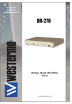
I/O connection
Product marking
Direction
Description
Digital in –
Input
Digital in –
DIDI+
DODO+
Digital in +
Input
Digital in +
Status –
Output
Alarm relay (status) contact
Status +
Output
Alarm relay (status) contact
The Status output is a potential free, opto-isolated normally closed solid-state relay. This can be configured to
monitor various alarm events within the RFIR unit, see WeOS Management Guide. An external load in series with
an external voltage source is required for proper functionality. For voltage/current ratings, see Interface
specification section.
The Digital in is an opto-isolated
digital input which can be used to
monitor external events. For voltage/current ratings, see Interface
Specification section:
External
Load
1
2
3
4
Status
V
+
Digital In
V
–
IO / Relay output
Connect resistance
Isolation to
Connection
Connector size
Maximum voltage/current
IO / Digital input
Voltage levels
Isolation to
Connection
Connector size
Maximum voltage
18
30 W
All other
Detachable screw terminal
0.2 – 2.5 mm2 (AWG 24 – 12)
60 VDC / 80 mA
Vih > 8V Vil < 5V
Iin = 2.9mA @60V
All other
Detachable screw terminal
0.2 – 2.5 mm2 (AWG 24 – 12)
60 VDC
6641-22810
LED indicators Power/CPU
LED
ON
DC1
DC2
AC1
FRNT
RSTP
USR1
TX/FX ports
6641-22810
Status
OFF
GREEN
RED
Description
Unit has no power.
All OK, no alarm condition.
Alarm condition, or until unit has
started up. (Alarm conditions are configurable,
see ''WeOS Management Guide'').
BLINK
Location indicator ("Here I am!").
Activated when connected to IPConfig
Tool,
or upon request from Web or CLI.
OFF
Unit has no power.
GREEN
Power OK on DC1.
RED
+DC1 input voltage is below operating
voltage limit
OFF
Unit has no power.
GREEN
Power OK on DC2.
RED
+DC2 input voltage is below operating
voltage limit
OFF
Unit has no power
GREEN
Power OK on AC1
OFF
FRNT disabled.
GREEN
FRNT OK.
RED
FRNT Error.
BLINK
Unit configured as FRNT Focal Point.
OFF
RSTP disabled.
GREEN
RSTP enabled.
BLINK
Unit elected as RSTP/STP root switch.
Configurable, see WeOS Management Guide
OFF
No link.
GREEN
Link established.
GREEN
Data traffic indication.
FLASH
YELLOW Port alarm and no link. Or if FRNT or
RSTP mode, port is blocked.
19
User Guid
e
ustri AB
6100-0000
SFP
Transceive
rs
Westermo Teleind
See SFP Transceivers data sheet for supported SFP transceivers.
Note: The unit supports Westermo labelled transceivers only.
See Transceiver User Guide 6100-0000 for transceiver handling
instructions.
©
SFP Transceivers
Deviations
With copper transceiver 1100-0148 the specified operating
temperature on the RFI and RFIR series is 0 to 50ºC.
FRNT reconfiguration times can not be guaranteed with
copper transceivers.
20
ESD Protecti
on
www. weste
rmo.c om
6641-22810
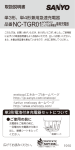
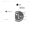
Mounting
This unit can either be rack-mouned or wall-mounted, see figures below.
Rack mouting
For mounting into rack, use M6x25 or 1/4"x1" screws.
Wall mounting
If mounting onto a wall, use maximum Ø6,4 mm or 1/4"screws.
Earth connection
For correct function, the ground connection on the unit needs to be properly connected
to a solid ground. See figure.
Protective earth
6641-22810
21
Getting Started
This product runs Westermo Operating System (WeOS) which provides several
management tools that can be used for configuration of the unit.
• WeConfig
WeConfig is a Network configuration management tool (NCM) made for
commissioning and maintenance of components in a network.
• Web
Configuration of the unit using the web browser.
• CLI
Configuration of the unit via the Command Line Interface.
If the computer is located in the same subnet as the switch you can easily use a web
browser to configure the unit. Within the web you can configure most of the available
functions.
For advanced network settings and more diagnostic information, please use the CLI.
Detailed documentation is available in the chapter ”The Command Line Management
Tool” in the WeOS management guide.
Factory default IP address: 192.168.2.200 (and DHCP client)
Netmask:
255.255.255.0
Gateway:
Disabled
Note! If you are not sure about the subnet – consult your network administrator.
Configuration
Configure the unit via Web browser
The unit can easily be configured via a Web browser.
Open the link http://192.168.2.200 in your web browser, and you will be prompted with
a Login screen, where the default settings for Username and Password are:
Username: admin
Password: westermo
Once you have logged in, you can use the extensive integrated help function describing
all configuration options. Two common task when configuring a new switch is to assign
appropriate IP settings, and to change the password of the admin account.
The password can be up to 64 characters long, and should consist of printable ASCII
characters (ASCII 33-126); 'Space' is not a valid password character.
22
6641-22810
Referring documents
All needed documentation can be downloaded from the product webpage. Related
software tools are available in the folder software tools under technical support on the
Westermo website.
Type
Management Guide
Description
Westermo OS management guide
Document number
6101-3201
Cable factory reset on RedFox Industrial Rack
It is possible to set the unit to factory default settings by using a standard (straight)
Ethernet RJ-45 cable.
1. Power off the switch and disconnect all Ethernet cables (including copper and
fibre).
2. Connect an Ethernet cable between Ethernet port 1 and Ethernet port 2.
The ports need to be connected directly by an Ethernet cable, i.e., not via a hub
or switch. Use a straight cable - not a cross-over cables - when connecting the
ports.
3. Power on the unit.
4. Wait for the unit to start up. Control that the ON LED is flashing red.
The ON LED flashing indicates that the unit is now ready to be reset to factory
default. You now have the choice to go ahead with the factory reset, or to skip
factory reset and boot as normal.
• Go ahead with factory reset: Acknowledge that you wish to conduct the
factory reset by unplugging the Ethernet cable. The ON LED will stop flashing. This initiates the factory reset process, and the unit will restart with
factory default settings. When the switch has booted up, the ON LED will
show a green light, and is now ready to use.
• Note! Do not power off the unit while the factory reset process is in progress. Skip the factory reset: To skip the factory reset process, just wait for
approximately 30 seconds (after the ON LED starts flashing RED) without
unplugging the Ethernet cable. The switch will conduct a normal boot with
the existing settings.
6641-22810
23
Westermo • SE-640 40 Stora Sundby, Sweden
Tel +46 16 42 80 00 Fax +46 16 42 80 01
E-mail: [email protected]
www.westermo.com
Sales Units
Westermo Data Communications
China
[email protected]
www.cn.westermo.com
France
[email protected]
www.westermo.fr
Germany
[email protected]
www.westermo.de
North America
[email protected]
www.westermo.com
Singapore
[email protected]
www.westermo.com
Sweden [email protected]
www.westermo.se
United Kingdom
[email protected]
www.westermo.co.uk
Other Offices
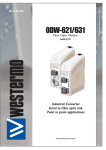
For complete contact information, please visit our website at www.westermo.com/contact
or scan the QR code with your mobile phone.
REV.A 6641-22810 2014-11 Westermo Teleindustri AB, Sweden – A Beijer Electronics Group Company