1
6643-22701
Lynx DSS
WeOS
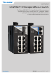
L108-F2G-S2 EX / L208-F2G-S2 EX
Industrial Ethernet
8-port Device Server Switch
www.westermo.com
© Westermo Teleindustri AB
User Guide
Safety
!
Warning
Do not open connected unit. Hazardous voltage may occur within this unit when
connected to power supply.
Note that this unit can be connected to two different power sources.
When this unit is operated at an ambient temperature above +55°C (+131°F),
the External Surface of Equipment may exceed Touch Temperature Limit according
to EN/IEC/UL 60950-1.
To reduce the risk of fire, use only No. 26 AWG or larger telecommunication
line cord.
For more information see General safety 100-5001.
License Information
This device contains public available software which is under the GPL license.
For more information see legal.pdf included with all firmware releases.
This product includes software developed by the OpenSSL Project for use in the
OpenSSL Toolkit. http://www.openssl.org
Legal information
The contents of this document are provided “as is”. Except as required by applicable
law, no warranties of any kind, either express or implied, including, but not limited to,
the implied warranties of merchantability and fitness for a particular purpose, are made
in relation to the accuracy and reliability or contents of this document. Westermo
reserves the right to revise this document or withdraw it at any time without prior
notice.
Under no circumstances shall Westermo be responsible for any loss of data or income
or any special, incidental, and consequential or indirect damages howsoever caused.
More information about Westermo can be found at the following Internet address:
http://www.westermo.com
2
6643-22701
ATEX certification
ATEX certification number
Baseefa12ATEX0119X
Standards
EN 60079-0:2012, EN 60079-15:2010, EN 60079-28:2007
Certification code
Ex nA [op is T4] IIC T3 Gc (–40°C ≤ Ta ≤ +70°C)
ATEX code
II 3G
Specific Conditions of Use
The equipment must be installed in an area of not more than pollution degree 2 in
accordance with IEC/EN 60664-1, and in an enclosure that provides a minimum degree of
protection of at least IP54 and complies with the relevant requirements of EN 60079-0
and EN 60079-15.
All external connections to the equipment and, where applicable, the SFP modules must
not be inserted or removed unless either the area in which the equipment is installed is
known to be non-hazardous, or the circuits connected have been de-energized.
The network cables once installed must be properly fixated by the use of cable ties or
similar to reduce the risk of accidently withdrawing the plugs.
Equipment input parameters
Power Connector: +DC1, +DC2 & –COM
Working Voltage Range = 24 V to 48 VDC.
I/O Connector: ‘Status +’ & ‘Status –’ and ‘Digital in +’ and ‘Digital in –’
Maximum I/P Voltage = 60 VDC.
6643-22701
3
SFP option approved transceivers
SFP Transceivers, 100 Mbit
1100-0131 MLC2, Multimode, LC-Connector, 2 km, 1310 nm
1100-0132 SLC20, Singlemode, LC-Connector, 20 km, 1310 nm
1100-0133 SLC40, Singlemode, LC-Connector, 40 km, 1310 nm
1100-0134 SLC80, Singlemode, LC-Connector, 80 km, 1550 nm
1100-0140 SLC120, Singlemode, LC-Connector, 120 km, 1550 nm
BiDi Transceivers, 100 Mbit
1100-0145 SLC15-BiDi-A, Singlemode, BiDi, 20 km, 1310 nm TX, 1550 nm RX
1100-0146 SLC15-BiDi-B, Singlemode, BiDi, 20 km, 1550 nm TX, 1310 nm RX
1100-0152 MLC2-BiDi-A, Multimode, BiDi, 2 km, 1310 nm TX, 1550 nm RX
1100-0153 MLC2-BiDi-B, Multimode, BiDi, 2 km, 1550 nm TX, 1310 nm RX
SFP Transceivers, 1 Gbit
1100-0144 GMLC550-SX, Multimode, LC-Connector, 550 m, 850 nm, SX
1100-0147 GMLC2-SX+, Multimode, LC-Connector, 2 km, 1310 nm, SX+
1100-0141 GSLC10-LX, Singlemode, LC-Connector, 10 km, 1310 nm, LX
1100-0142 GSLC50-XD, Singlemode, LC-Connector, 50 km, 1550 nm, XD
1100-0143 GSLC80-ZX, Singlemode, LC-Connector, 80 km, 1550 nm, ZX
1100-0171 GSLC110-EZX, Singlemode, LC-Connector, 110 km, 1550 nm, EZX
BiDi Transceiver, 1 Gbit
1100-0156 GSLC20-BiDi-A, Singlemode, BiDi, 20 km, 1310 nm TX, 1490 nm RX
1100-0157 GSLC20-BiDi-B, Singlemode, BiDi, 20 km, 1490 nm TX, 1310 nm RX
Copper Transceiver, 1 Gbit
1100-0148 GC100, Copper, RJ45, 100 m, 1000BaseT
4
6643-22701
ATEX-Zertifizierung
ATEX-Zulassungsnummer
Baseefa12ATEX0119X
Standards
EN 60079-0:2012, EN 60079-15:2010, EN 60079-28:2007
Zertifizierungscode
Ex nA [op ist T4] IIC T3 Gc (–40 °C ≤ Ta ≤ +70 °C)
ATEX-Code
II 3G
Spezifische Einsatzbedingungen
Die Geräte müssen in einem Bereich welcher einem maximalen Verschmutzungsgrad der
Stufe 2 gemäß IEC/EN 60664-1 entspricht und in einem Gehäuse, das einen Schutzgrad
von mindestens IP54 bietet und die relevanten Anforderungen von N 60079-0 und EN
60079-15 erfüllt, installiert werden.
Alle äußeren Anschlüsse des Gerätes und auch die SFP-Module dürfen nur dann verbunden oder getrennt werden, wenn entweder der Bereich, in dem das Gerät installiert ist,
nachweislich ungefährlich ist, oder die verbundenen Stromkreise spannungsfrei sind.
Die Netzwerkkabel müssen nach der Installation mithilfe von Kabelbindern oder ähnlichem Material ordnungsgemäß befestigt werden, um ein versehentliches Abziehen der
Stecker zu verhindern.
Eingangsparameter der Geräte
Stromversorgung: +DC1, +DC2 & –COM
Betriebsspannungsbereich = 24 V to 48 VDC.
I/O-Anschluss: ‘Status +’ & ‘Status –’ und ‘Digital in +’ und ‘Digital in –’
Maximale I/P-Spannung = 60 VDC.
6643-22701
5
Für SFP-Option zugelassene Transceiver
SFP-Transceiver, 100 Mbit
1100-0131 MLC2, Multimode, LC-Anschluss, 2 km, 1310 nm
1100-0132 SLC20, Singlemode, LC-Anschluss, 20 km, 1310 nm
1100-0133 SLC40, Singlemode, LC-Anschluss, 40 km, 1310 nm
1100-0134 SLC80, Singlemode, LC-Anschluss, 80 km, 1550 nm
1100-0140 SLC120, Singlemode, LC-Anschluss, 120 km, 1550 nm
BiDi-Transceiver, 100 Mbit
1100-0145 SLC15-BiDi-A, Singlemode, BiDi, 20 km, 1310 nm TX, 1550 nm RX
1100-0146 SLC15-BiDi-B, Singlemode, BiDi, 20 km, 1550 nm TX, 1310 nm RX
1100-0152 MLC2-BiDi-A, Multimode, BiDi, 2 km, 1310 nm TX, 1550 nm RX
1100-0153 MLC2-BiDi-B, Multimode, BiDi, 2 km, 1550 nm TX, 1310 nm RX
SFP-Transceiver, 1 Gbit
1100-0144 GMLC550-SX, Multimode, LC-Anschluss, 550 m, 850 nm, SX
1100-0147 GMLC2-SX+, Multimode, LC-Anschluss, 2 km, 1310 nm, SX+
1100-0141 GSLC10-LX, Singlemode, LC-Anschluss, 10 km, 1310 nm, LX
1100-0142 GSLC50-XD, Singlemode, LC-Anschluss, 50 km, 1550 nm, XD
1100-0143 GSLC80-ZX, Singlemode, LC-Anschluss, 80 km, 1550 nm, ZX
1100-0171 GSLC110-EZX, Singlemode, LC-Anschluss, 110 km, 1550 nm, EZX
BiDi-Transceiver, 1 Gbit
1100-0156 GSLC20-BiDi-A, Singlemode, BiDi, 20 km, 1310 nm TX, 1490 nm RX
1100-0157 GSLC20-BiDi-B, Singlemode, BiDi, 20 km, 1490 nm TX, 1310 nm RX
Kupfer-Transceiver, 1 Gbit
1100-0148 GC100, Kupfer, RJ45, 100 m, 1000BaseT
6
6643-22701
Certification ATEX
Numéro de certification ATEX
Baseefa12ATEX0119X
Normes
EN 60079-0:2012, EN 60079-15:2010, EN 60079-28:2007
Code de certification
Ex nA [op is T4] IIC T3 Gc (–40°C ≤ Ta ≤ +70°C)
Code ATEX
II 3G
Conditions spéciales d'utilisation
L'équipement doit être installé dans une zone où le degré de pollution ne dépasse pas le
degré 2 conformément à l'IEC/EN 60664-1, et dans un boîtier qui fournit un niveau de
protection au moins égal à IP54 et conforme aux exigences applicables à EN 60079-0 et
EN 60079-15
Toutes les connexions externes à l'équipement et, le cas échéant, les modules SFP ne doivent pas être insérés ou retirés sauf si la zone dans laquelle l'équipement est installé est
reconnue comme non dangereuse, ou si les circuits raccordés sont hors-tension.
Une fois les câbles réseau installés, ils doivent être correctement fixé grâce à des attaches de câbles ou autre élément semblable afin de réduire le risque de débranchement
accidentel.
Paramètres d'entrée des équipements
Connecteur d'alimentation : +DC1, +DC2 & –COM
Double entrée d'alimentation 24 V à 48 VCC
Connecteur E/S : « Statut + » et « Statut – » et « Entrée digitale + » et « Entrée digitale – »
Tension maximale I/P = 60 VCC.
6643-22701
7
Transmetteurs optionnels SFP certifiés
Transmetteurs SFP, 100 Mbit
1100-0131 MLC2, multimode, connecteur LC, 2 km, 1310 nm
1100-0132 SLC20, monomode, connecteur LC, 20 km, 1310 nm
1100-0133 SLC40, monomode, connecteur LC, 40 km, 1310 nm
1100-0134 SLC80, monomode, connecteur LC, 80 km, 1550 nm
1100-0140 SLC120, monomode, connecteur LC, 120 km, 1550 nm
Transmetteurs Bi-Di, 100 Mbit
1100-0145 SLC15 Bi-Di A, monomode, Bi-Di, 20 km, 1310 nm TX, 1550 nm, RX
1100-0146 SLC15-Bi-Di-B, monomode, Bi-Di, 20 km, 1550 nm TX, 1310 nm RX
1100-0152 MLC2-BiDi-A, multimode, Bi-Di, 2 km, 1310 nm TX, 1550 nm RX
1100-0153 MLC2-BiDi-B, multimode, Bi-Di, 2 km, 1550 nm TX, 1310 nm RX
Transmetteurs SFP, 1 Gbit
1100-0144 GMLC550-SX, multimode, connecteur LC, 550 m, 850 nm, SX
1100-0147 GMLC2-SX+, multimode, connecteur LC, 2 km, 1310 nm, SX+
1100-0141 GSLC10-LX, monomode, connecteur LC, 10 km, 1310 nm, LX
1100-0142 GSLC50-XD, monomode, connecteur LC, 50 km, 1550 nm, XD
1100-0143 SLC80, monomode, connecteur LC, 80 km, 1550 nm, ZX
1100-0171 GSLC110, monomode, connecteur LC, 110 km, 1550 nm, EZX
Transmetteurs Bi-Di, 1 Gbit
1100-0156 GSLC20-BiDi-A, monomode, Bi-Di, 20 km, 1310 nm TX, 1490 nm RX
1100-0157 GSLC20-BiDi-B, monomode, Bi-Di, 20 km, 1490 nm TX, 1310 nm RX
Transmetteurs cuivre, 1 Gbit
1100-0148 GC100, cuivre, RJ45, 100 m, 1000BaseT
8
6643-22701
Maintenance
No maintenance is required, as long as the unit is used as intended within the specified
conditions.
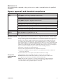
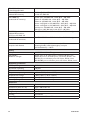
Agency approvals and standards compliance
Type
EMC
Safety
Marine
Approval / Compliance
EN 61000-6-1, Immunity residential environments
EN 61000-6-2, Immunity industrial environments
EN 61000-6-3, Emission residential environments
EN 61000-6-4, Emission industrial environments
EN 55022 +A1, Emission IT equipment
EN 55024 +A1 + A2, Immunity IT equipment
FCC part 15 Class B
EN 50121-4, Railway signalling and telecommunications apparatus
IEC 62236-4, Railway signalling and telecommunications apparatus
UL/IEC/EN 60950-1, IT equipment
DNV Standard for Certification no. 2.4
Ex
EN 60079-0, EN 60079-15 and EN 60079-28
FCC Part 15.105 This equipment has been tested and found to comply with the limits for a Class B digital
device, pursuant to Part 15 of the FCC Rules. These limits are designed to provide reasonNotice:
able protection against harmful interference in a residential installation. This equipment
generates, uses and can radiate radio frequency energy and, if not installed and used in
accordance with the instructions, may cause harmful interference to radio communications. However, there is no guarantee that interference will not occur in a particular installation. If this equipment does cause harmful interference to radio or television reception,
which can be determined by turning the equipment off and on, the user is encouraged to
try to correct the interference by one or more of the following measures:
… Reorient or relocate the receiving antenna
… Increase the separation between the equipment and receiver
… Connect the equipment into an outlet on a circuit different from that to which the
receiver is connected
… Consult the dealer or an experienced radio/TV technician for help.
Corrosive
environment
Notice:
6643-22701
This product has been successfully tested in a corrosion test according to
IEC 60068-2-60, method 3. This means that the product meets the requirements
to be placed in an environment classified as ISA-S71.04 class G3.
Note! If the product is placed in a corrosive environment, it is important that all
un-used connector sockets are protected with a suitable plug in order to avoid
corrosion attacks on the gold plated pins in connectors.
9
Declaration of Conformity
Westermo Teleindustri AB
Declaration of conformity
The manufacturer
Westermo Teleindustri AB
SE-640 40 Stora Sundby, Sweden
Herewith declares that the product(s)
Type of product
Model 1
Ethernet device server switch
Lynx DSS
L*08-F2G-S2-EX*
is in conformity with the following EC directive(s).
No
Short name
2004/108/EC
2011/65/EU
Electromagnetic Compatibility (EMC)
Restriction of the use of certain hazardous substances in electrical and
electronic equipment (RoHS)
References of standards applied for this EC declaration of conformity.
No
Title
Issue
EN 61000-6-1
2007
EN 55024
Electromagnetic compatibility – Immunity for residential
environments
Electromagnetic compatibility – Immunity for industrial
environments
Electromagnetic compatibility – Emission for residential
environments
Electromagnetic compatibility – Emission for industrial
environments
Information technology equipment - Immunity
EN 55022
Information technology equipment - Emission
EN 50121-4
Railway applications - Electromagnetic compatibility
Emission and immunity of the signalling and
telecommunications apparatus
EN 60079-0
Explosive atmospheres
Equipment – General requirements
Electrical apparatus for explosive gas atmospheres –
Construction, test and marking of type of protection “n”
Explosive atmospheres - Protection of equipment and
transmission systems using optical radiation
EN 61000-6-2
EN 61000-6-3
EN 61000-6-4
EN 60079-15
EN 60079-28
The last two digits of the year in which the CE marking was affixed:
2005
2007
2007
1998
+A1:2001
+A2:2003
2006
+A1:2007
2006
2012
2010
2007
13
Pierre Öberg
Technical Manager
08th December 2013
1
The first “*” in the model name can be any alphanumeric character, indicating software version. The second “*” in the
model name can be any alphanumeric characters indicating customer specific models, or blank.
10
Postadress/Postal address
Tel.
Telefax
Postgiro
Bankgiro
Org.nr/
Corp. identity number
Registered office
S-640 40 Stora Sundby
Sweden
016-428000
Int+46 16428000
016-428001
Int+46 16428001
52 72 79-4
5671-5550
556361-2604
Eskilstuna
6643-22701
Product description
Status
Ports
Description
Warranty period
Active
6 x RJ-45, 10/100BaseT. 4 x SFP, 100/1000 Mbit/s. 2 x RJ-45, RS-232/422/485.
Managed Device Server Switch with routing functionality
5 years
Approvals
Marine
DNV Standard for Certification no. 2.4
EMC (Electromagnetic Compatibility)
EN 61000-6-1
Immunity residential environments
EN 61000-6-2
Immunity industrial environments
EN 61000-6-3
Emission residential environments
EN 61000-6-4
Emission industrial environments
EN 55022 +A1
Emission IT equipment
EN 55024 + A1 + A2
Immunity IT equipment
FCC part 15
Class B
EN 50121-4
Railway signalling and telecommunications apparatus
IEC 62236-4
Railway signalling and telecommunications apparatus
EMC specifications
EN 61000-4-2,
Contact: ±6 kV
ESD
Air: ±8 kV
EN 61000-4-4,
Power port: ±2 kV
fast transients
Ethernet: ±2 kV
Status out/Digital in: ±2 kV
Serial ports: ±2 kV
Enclosure: ±2 kV
EN 61000-4-5,
Power port
surge
L-L: ±0.5 kV, 2 Ω, 18 μF
L-E: ±2 kV, 42 Ω, 0.5 μF
L-L: ±1 kV, 42 Ω, 0.5 μF
L-E: ±2 kV, 12 Ω, 9 μF
L-L: ±1 kV, 12 Ω, 9 μF
Ethernet
L-E: ±2 kV, 2Ω, 0.5 μF
Status out/Digital in
L-E: ±2 kV, 42 Ω, 0.5 μF
L-L: ±1 kV, 42 Ω, 0.5 μF
RS-232
L-E: ±2 kV, 2 Ω, 0.5 μF
EN 61000-4-8,
power frequency magnetic field
6643-22701
RS-422/485
L-E: ±2 kV, 42 Ω, 0.5 μF
300 A/m; 0, 16.7, 60 Hz
1000 A/m; 50 Hz
11
EN 61000-4-9,
pulsed magnetic field
EN 61000-4-3,
radiated RF immunity
EN 61000-4-6,
conducted RF immunity
EN 55022,
radiated RF emmision,
FCC Part 15/ DNV 2.4
EN 55022,
conducted RF emmision,
DNV 2.4,
compass safe distance
Safety
Safety
EN 60950-1,
dielectric strength
Reliability prediction
MTBF, operating
Service life, operating
Climatic
Temperature, operating
Temperature, storage
Humidity, operating
Humidity, storage
Enclosure
Enclosure
Dimensions (W x H x D)
Weight
Degree of protection
Cooling
Mounting
12
300 A/m
20 V/m @ (80 – 2700) MHz
1 kHz sine, 80% AM
Power port: 10 V, 80% AM, 1 kHz; (0.15 – 80) MHz
Ethernet: 10 V, 80% AM, 1 kHz; (0.15 – 80) MHz
Ethernet: 10 V, 80% AM, 1 kHz; (0.15 – 80) MHz
Status out/Digital in: 10 V, 80% AM, 1 kHz; (0.15 – 80) MHz
Status out/Digital in: 10 V, 80% AM, 1 kHz; (0.15 – 80) MHz
Serial ports: 10 V, 80% AM, 1 kHz; (0.15 – 80) MHz
Earth port: 10 V, 80% AM, 1 kHz; (0.15 – 80) MHz
EN 55022/FCC Part 15/DNV 2.4, Class B / DNV bridge
EN 55022/FCC Part 15/DNV 2.4, Class B / DNV bridge
Standard compass (5.4°/H deviation) = 15 cm
Steering/standby steering/emergency compass
(18°/H deviation) = 10 cm
UL/IEC/EN 60950-1, IT equipment
Power port to all other ports: 1.5 kVrms, 50 Hz, 1 min
Ethernet ports to all other ports: 1.5 kVrms, 50 Hz, 1 min
RS-232 port to all other ports: 1.5 kVrms, 50 Hz, 1 min
RS-422/485 port to all other ports: 1.5 kVrms, 50 Hz, 1 min
517 000 hours
10 years
–40 to +70°C (–40 to +158°F)
–50 to +85°C (–58 to +185°F)
5 to 95 % relative humidity
5 to 95 % relative humidity
Fire enclosure
52.5 x 100 x 101 mm
0.7 kg
IP 40
Convection
Horizontal on 35 mm DIN-rail
6643-22701
Mechanical
IEC 60068-2-6,
vibration
IEC-60068-2-27, shock
IEC 60068-2-27, bump
Interface specifications, power
Rated voltage
Operating voltage
Rated current
Rated frequency
Inrush current
Startup current*
Polarity
Redundant power input
Isolation to
Connection
Connector size
Shielded cable
IEC 60068-2-6,(sine), operating
3 – 13.2 Hz: 1mm
13.2 – 100 Hz: 0.7 g
5.5 – 30 Hz: 1.5 g
30 – 50 Hz: 0.42 mm
50 – 500 Hz: 4.2 g
IEC 60068-2-64 (random), operating
5 – 20 Hz: 2 m²/s³,
20 – 2000 Hz: – 3 dB/oct
Operating:
30 g, 11 ms
100 g, 6 ms**
Operating:
10 g, 11 ms
24 to 48 VDC
19 to 60 VDC
250 mA (380 mA) @ 24 VDC (with 500 mA USB load)
120 mA (188 mA) @ 48 VDC (with 500 mA USB load)
DC
22.7·10-3 A²s @ 48 VDC
2 x Rated current
Reverse polarity protected
Yes
All other
Detachable screw terminal
0.2 – 2.5 mm² (AWG 24 – 12)
Not required
* External supply current capability for proper start-up
Interface specifications, 10/100BaseTX
Electrical specification
IEEE std 802.3. 2005 Edition
Data rate
10 Mbit/s, 100 Mbit/s, manual or auto
Duplex
Full or half, manual or auto
Circuit type
TNV-1
Transmission range
Up to 150 m with CAT5e cable or better*
Isolation to
All other
Connection
RJ-45, auto MDI/MDI-X
Cabling
Shielded CAT5e or better is recommended
Conductive housing
Yes
Number of ports
4
* Refer to Safety section.
6643-22701
13
Interface specifications, 100/1000SFP
Optical/Electrical specification
IEEE std 802.3. 2005 Edition
Data rate
100 Mbit/s or 1000 Mbit/s transceivers supported
Duplex
Full or Auto, depending on transceiver
Transmission range
Depending on tranceiver
Connection
SFP slot holding fibre transceiver or copper transceiver
Number of ports
1 or 2
Interface specifications, RS-232
Electrical specification
EIA RS-232
Data rate
300 bit/s – 115.2 kbit/s
Data format
7 or 8 data bits, Odd, even or none parity, 1 or 2 stop bits
Protocol
Transparent, optimised by packing algorithm
Circuit type
SELV
Transmission range
15 m / 49 ft
Isolation to
All other
Connection
RJ-45 according to EIA-561
Shielded cable
Recommended
Conductive housing
Yes
Number of ports
1
Interface specifications, RS-422/485
Electrical specification
Configurable for EIA RS-232 or EIA RS-422/485
Data rate
50 bit/s – 2 Mbit/s
Data format
7 or 8 data bits, Odd, even or none parity, 1 or 2 stop bits
(2 stop bits only when no parity is set)
Circuit type
TNV-1
Transmission range
Up to 1200 m / 0.74 mi, depending on data rate and cable
type
Isolation to
All other
Connection
RJ-45 according to EIA-561
Shielded cable
Not required, but recommended in railway installations close
to the rails.*
Conductive housing
Yes
Number of ports
1
* To minimise the risk of interference, a shielded cable is recommended when the cable is located inside 3 m
boundary or the cable is longer than 30 m and inside 10 m boundary to the rails and connected to this port.
14
6643-22701
Interface specifications, I/O relay output
Maximum voltage / current
60 VDC / 80 mA
Connect resistance
Max 30 Ω
Isolation to
All other
Connection
Detachable screw terminal
Connector size
0.2 – 2.5 mm² (AWG 24 – 12)
Interface specifications, I/O Digital output
Maximum volt / current
60 VDC / 2 mA
Voltage_levels
Logic one: >12V
Logic zero: <1V
Isolation to
All other
Connection
Detachable screw terminal
Connector size
0.2 – 2.5 mm² (AWG 24 – 12)
Interface specifications, USB
Electrical specification
USB 2.0 host interface
Data rate
Up to 12 Mbit/s (full-speed mode)
Circuit type
SELV
Maximum supply current
500 mA
Connection
USB receptacle connector type A
Interface specifications, console
Electrical specification
LVTTL/LVCMOS-level
Data rate
115.2 kbit/s
Data format
8 data bits, no parity, 1 stop bit, no flow control
Circuit type
SELV
Connection
2.5 mm jack, use only Westermo cable 1211-2027
Accessories
Description
Art no
Westermo console cable
1211-2027
RJ45 to terminal block
1200-2490
RJ45 to DB9 cable
1211-2210
SFP Transceivers
Supported transceivers
Firmware prior to 4.4.0 accepts Westermo branded
transceivers only. From 4.5.0 other transceivers are accepted with a notice and the
unit will no longer be UL approved. Temp.specifications are also depending on the
used transeivers.
Note: To comply with UL60950-1 only UL recognized SFP transceivers should be used.
Deviations
With copper transceiver 1100-0148 the specified operating temperature on Lynx
is 0 to +50ºC (32 to +122°F).
FRNT reconfiguration times can not be guaranteed with copper transceivers.
6643-22701
15
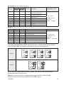
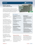
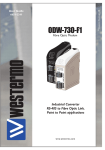
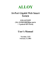
Safety control drawing
Location of interface ports and LED’s
LED Indicators (for details see page 16)
Power connection (for details see page 9 and 15)
USB
Position
1
2
3
4
Shield
Direction* / description
Out / VBUS
In/out / D–
In/out / D+
GND
PE
Output values
Uout = 5 VDC max
Iout = 500 mA max
SFP transceivers (for details see page 11)
RS-232, RS-422/485 (for details see page 10 and 13)
Ethernet connection TX (4 ports)
Position Signale Direction Description
No.1
I/O connection
(for details see page 11 and 15)
Input/output values
TD+
In/Out
Transmitted/Received data
No. 2
TD–
In/Out
Transmitted/Received data
No. 3
RD+
In/Out
Transmitted/Received data
No. 4
–
No. 5
–
No. 6
RD–
No. 7
–
Per port:
U = ± 1 V (4μV/s)
I = ± 20 mA
Not Connected
Transmitted/Received data Data rate:
10/100 Mbit/s
Not Connected
No. 8
–
Not Connected
Shield
Not Connected
In/Out
Connected to PE
Galvanically isolated via signal transformers and capacitively isolated to
GND/PE through a 2kV 1000pF capacitor.
See user manual for proven transient protection.
RJ-45 connector (Front view)
Male
Pin 8
16
Female
Pin 1
Pin 8
Pin 1
Pin 1
Pin 8
6643-22701
RS-422/485 (for more details see below)
Signal
Position
RS-422
(4-wire)
RS-485
(2-wire)
Direction Description
Input/Output values
No. 1
T+
T+/R+
Out/In
RS-422: Transmit
RS-485: Transmit/Receive
No. 2
T–
T–/R–
Out/In
RS-422: Transmit
RS-485: Transmit/Receive
No. 3
R–
–
In
RS-422: Receive
No. 4
–
–
–
Not used
No. 5
–
–
–
Not used
No. 6
R+
–
In
RS-422: Receive
No. 7
–
–
–
Not used
No. 8
–
–
–
Not used
U = 5 V max
I = 250 mA max
Data rate:
50 bit/s – 2 Mbit/s
RS-232
Position
Signal
No. 1
DSR
Direction Description
Out
Data Set Ready
Input/Output values
No. 2
DCD
Out
Data Carrier Detect
No. 3
DTR
In
Data Terminal Ready
No. 4
SG
–
Signal Ground, not chassis ground
No. 5
RD
Out
Receive Data
No. 6
TD
In
Transmit Data
No. 7
CTS
Out
Clear To Send
No. 8
RTS
In
U = ±12 V max
I = ±60 mA max
Data rate:
300 bit/s – 115.2 kbit/s
Request To Send
Lynx DSS is equipped with internal termination that is configurable through software
in RS-422/485 mode. The following termination schemes are supported:
No termination
Terminate Rx
Terminate Tx and Rx
Terminate Tx
Tx
Tx
Tx
Tx
Rx
Rx
Rx
Rx
RS-422
No termination
Termination
RS-485
When the unit is powered-off or during reboot, any internal termination will be
disconnected from the signal lines.
Note: Due to that the port is configurable for both RS-232 and RS-422/485,
there are no fail-safe biasing available for RS-422/485 signals.
6643-22701
17
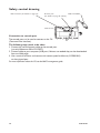
Safety control drawing
I/O connection (for details see page 11)
Console port
(for details see page 11 and 15)
Cable 1211-2027
Bottom view
Connection to console port
The console port can be used to connect to the CLI
(Command Line Interface).
The following steps needs to be taken
1. Connect the serial diagnostic cable to the console port
(use only Westermo cable 1211-2027).
2. Connect cable to your computer (USB port, if drivers are needed they can be downloaded
from our Web page).
3. Use a terminal emulator and connect with correct speed and format (115200, 8N1)
to the assigned port.
For more information about the CLI, see the WeOS management guide.
18
6643-22701
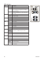
Safety control drawing
Power connection
4-position
Product
marking
Direction
Description
No. 1
+DC1
Input
Supply voltage input DC1
No. 2
+DC2
Input
Supply voltage input DC2
No. 3
-COM
Input
Common
No. 4
-COM
Input
Common
1
Input values
2
3
4
Uin = (19 – 60) VDC
Iin = 380 mA @ 24 VDC
PIn = 9.1 W @ 24 VDC
Lynx supports redundant power connection. The positive inputs are +DC1 and +DC2, the negative input for
both supplies are –COM. Connect the primary voltage (e.g. +24 VDC) to the +DC1 pin and return to one of the
–COM pins on the power input.
I/O connection
1
2
3
4
4-position
Product
marking
Direction
No. 1
Status +
Output
Alarm relay (status) contact Uin = 60 VDC max
No. 2
Status –
Output
Alarm relay (status) contact Iin = 80 mA max
No. 3
Digital in +
Input
Digital in +
Uin = 60 VDC max
No. 4
Digital in –
Input
Digital in –
Iin = 2 mA max
Description
Input / Output values
The Status output is a potential free, opto-isolated normally closed solid-state relay. This can be configured to monitor various alarm events within the Lynx unit, see WeOS Management Guide. An external load in series with an external voltage source is required for proper functionality.
For voltage/current ratings, see Interface Specification section.
Console port
Position Direction* / description Input/output values
No.1
In / out / GND
No. 2 Out / Tx
No. 3 In / Rx
U = 3.3 VDC max
I = 24 mA max
* Direction relative to this unit.
The Digital in is an opto-isolated
digital input which can be used to
monitor external events. For voltage/current ratings, see Interface
Specification section:
Lynx
External
Load
1
2
3
4
6643-22701
V
Status
+
V
Digital In
–
19
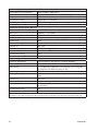
LED indicators
LED
Status
Description
ON
OFF
Unit has no power.
GREEN
All OK, no alarm condition.
RED
Alarm condition, or until unit has started up.
(Alarm conditions are configurable, see ''WeOS
Management Guide'').
BLINK
Location indicator ("Here I am!"). Activated when
connected to IPConfig Tool, or upon request from
Web or CLI.
OFF
Unit has no power.
GREEN
Power OK on DC1.
RED
Power failure on +DC1.
OFF
Unit has no power.
GREEN
Power OK on DC2.
RED
Power failure on +DC2.
OFF
FRNT disabled.
GREEN
FRNT OK.
RED
FRNT Error.
BLINK
Unit configured as FRNT Focal Point.
OFF
RSTP disabled.
GREEN
RSTP enabled.
BLINK
Unit elected as RSTP/STP root switch.
DC1
DC2
FRNT
RSTP
USR1
OFF
GREEN
Configurable, see WeOS Management Guide.
RED
Rx/TD, TD
OFF
No serial data received.
GREEN
FLASH
Serial data received.
Tx/RD, RD OFF
1 to 6
No serial data transmitted.
GREEN
FLASH
Serial data transmitted.
OFF
No Link.
GREEN
Link established.
GREEN
FLASH
Data traffic indication.
YELLOW Port alarm and no link. Or if FRNT or RSTP mode,
port is blocked.
20
6643-22701
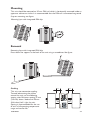
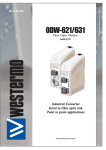
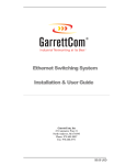
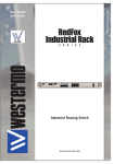
Mounting
This unit should be mounted on 35 mm DIN-rail, which is horizontally mounted inside an
apparatus cabinet or similar. It is recommended that the DIN-rail is connected to ground.
Snap on mounting, see figure.
Mounting Lynx with integrated DIN-clip:
Removal
Removing Lynx with integrated DIN-clip:
Press down the support at the back of the unit using a screwdriver. See figure.
Cooling
This unit uses convection cooling.
To avoid obstructing the airflow
around the unit, use the following
spacing rules. Minimum spacing 25 mm
(1.0 inch) above / below and 10 mm
(0.4 inches) left / right the unit.
Spacing is recommended for the use
of unit in full operating temperature
range and service life.
6643-22701
10mm
10mm
21
Getting Started
This product runs Westermo Operating System (WeOS) which provides several
management tools that can be used for configuration of the unit.
• IPConfig tool
This is a custom Westermo tool used for discovery of attached Westermo units.
Note! Version of IP Config tool must be 10.4.0 or higher.
• Web
Configuration of the unit using the web browser.
• CLI
Configuration of the unit via the Command Line Interface.
Username: admin
Password: westermo
If the computer is located in the same subnet as the switch you can easily use a web
browser to configure the unit. Within the web you can configure most of the available
functions.
For advanced network settings and more diagnostic information, please use the CLI.
Detailed documentation is available in the chapter ”The Command Line Management
Tool” in the WeOS management guide.
Factory default IP address: 192.168.2.200
Netmask:
255.255.255.0
Gateway:
Disabled
Note! If you are not sure about the subnet – consult your network administrator.
Configuration
Configure the unit via Web browser
The unit can easily be configured via a Web browser.
Open the link http://192.168.2.200 in your web browser, and you will be prompted with
a Login screen, where the default settings for Username and Password are:
Username: admin
Password: westermo
Once you have logged in, you can use the extensive integrated help function describing
all configuration options. Two common task when configuring a new switch is to assign
appropriate IP settings, and to change the password of the admin account.
The password can be up to 64 characters long, and should consist of printable ASCII
characters (ASCII 33-126); 'Space' is not a valid password character.
22
6643-22701
Referring documents
Type
Management Guide
Description
Westermo OS management guide
Document number
6101-3201
Factory default on L108-F2G-S2 EX / L208-F2G-S2 EX
It is possible to set the unit to factory default settings by using two straight standard
Ethernet RJ-45 cables.
1. Power off the switch and disconnect all Ethernet cables (copper and fibre).
2. Connect one Ethernet cable between Ethernet ports 3 and 6, and the other between
Ethernet ports 4 and 5.
The ports need to be connected directly by an Ethernet cable, i.e., not via a hub or
switch. Use a straight cable – not a cross-over cable – when connecting the ports.
3. Power on the unit.
4. Wait for the unit to start up. Control that the ON LED is flashing red.
The ON LED flashing indicates that the unit is now ready to be reset to factory
default. You now have the choice to go ahead with the factory reset, or to skip factory
reset and boot as normal.
• Go ahead with factory reset: Acknowledge that you wish to conduct the factory reset by unplugging the
Ethernet cables. The ON LED will stop flashing.
This initiates the factory reset process*, and after approximately 1 minute the unit
will restart with factory default settings. When the switch has booted up, the ON
LED will show a green light, and is now ready to use.
• Skip the factory reset:
To skip the factory reset process, just wait for approximately 30 seconds
(after the ON LED starts flashing RED) without unplugging the Ethernet cables. The switch will conduct a normal boot with the existing settings.
* Note Do not power off the unit while the factory reset process is in progress.
6643-22701
23
Westermo • SE-640 40 Stora Sundby, Sweden
Tel +46 16 42 80 00 Fax +46 16 42 80 01
E-mail: [email protected]
www.westermo.com
Sales Units
Westermo Data Communications
China
[email protected]
www.cn.westermo.com
France
[email protected]
www.westermo.fr
Germany
[email protected]
www.westermo.de
North America
[email protected]
www.westermo.com
Singapore
[email protected]
www.westermo.com
Sweden [email protected]
www.westermo.se
United Kingdom
[email protected]
www.westermo.co.uk
Other Offices
For complete contact information, please visit our website at www.westermo.com/contact
or scan the QR code with your mobile phone.
REV.A 6643-22701 2013-12 Westermo Teleindustri AB, Sweden – A Beijer Electronics Group Company