1
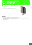
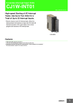
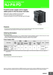
CJ-series I/O Control Unit / I/O Interface Unit CJ1W-IC/II CSM_CJ1W-IC/II_DS_E_2_1 Expand CJ/NJ-series with These Units • To expand a CJ/NJ-series Controller, connect an I/O Control Unit to the CPU Rack, and I/O Interface Unit to the Expansion Rack, and connect the two Units with I/O Expansion Cable. CJ1W-IC101 CJ1W-II101 Features • Rack-mountable Units enable expanding Controller capacity even when space is limited. • Easy-to-use connectors enable quick expansion without any settings. System Configuration The I/O Control Unit is connected directly to the CPU Unit. If it is not immediately to the right of the CPU Unit, correct operation may not be possible. The I/O Interface Unit is connected directly to the Power Supply Unit. If it is not immediately to the right of the Power Supply Unit, correct operation may not be possible. Power CPU Unit Supply Unit CJ1W-IC101 I/O Control Unit CPU Rack Power Supply Unit I/O Connecting Cable CJ1W-II101 I/O Interface Unit Expansion Rack Power Supply Unit I/O Connecting Cable CJ1W-II101 I/O Interface Unit 1 CJ1W-IC/II Ordering Information International Standards • The standards are abbreviated as follows: U: UL, U1: UL (Class I Division 2 Products for Hazardous Locations), C: CSA, UC: cULus, UC1: cULus (Class I Division 2 Products for Hazardous Locations), CU: cUL, N: NK, L: Lloyd, and CE: EC Directives. • Contact your OMRON representative for further details and applicable conditions for these standards. I/O Control Unit (Mounted on CPU Rack when Connecting Expansion Racks) Product name CJ-series I/O Control Unit Current consumption (A) Specifications Mount one I/O Control Unit on the CPU Rack when connecting one or more Expansion Racks. Connecting Cable: CS1W-CN@@3 Expansion Connecting Cable Connected Unit: CJ1W-II101 I/O Interface Unit Mount to the right of the CPU Unit. 5V 24 V 0.02 − Model CJ1W-IC101 Standards UC1, N, L, CE Note: Mounting the I/O Control Unit in any other location may cause faulty operation. I/O Interface Unit (Mounted on Expansion Rack) Product Name Current consumption (A) Specifications 5V 24 V 0.13 − Model Standards CJ-series I/O Interface Unit One I/O Interface Unit is required on each Expansion Rack. Connecting Cable: CS1W-CN@@3 Expansion Connecting Cable Mount to the right of the Power Supply Unit. CJ1W-II101 UC1, N, L, CE Note: Mounting the I/O Interface Unit in any other location may cause faulty operation. Accessories CJ1W-IC101 I/O Control Unit There is no accessory for the I/O Control Unit Unit. CJ1W-II101 I/O Interface Unit The following accessories come with I/O Interface Unit: Item Specification End Cover CJ1W-TER01 (necessary to be mouned at the right end of CPU Rack) End Plate PFP-M (2 pcs) External Interface I/O Control Unit CJ1W-IC101 I/O Interface Unit CJ1W-II101 II101 IC101 OUT OUT Output connector for I/O Connecting Cable Output connector for I/O Connecting Cable IN Input connector for I/O Connecting Cable 2 CJ1W-IC/II Connecting Expansion Racks CS/CJ-series I/O Connecting Cables are used to connect the CPU Rack and Expansion Racks. CS/CJ-series I/O Connecting Cables The CS/CJ-series I/O Connecting Cables have connectors with a simple lock mechanism are used to connect the CPU Rack to an Expansion Rack or to connect two Expansion Racks. CS/CJ-series I/O Connecting Cables Model number Cable length CS1W-CN313 0.3 m CS1W-CN713 0.7 m CS1W-CN223 2m CS1W-CN323 3m CS1W-CN523 5m CS1W-CN133 10 m CS1W-CN133-B2 12 m • Install the Racks and select I/O Connecting Cables so that the total length of all I/O Connecting Cables does not exceed 12 m. • The following diagram shows where each I/O Connecting Cable must be connected on each Rack. The Rack will not operate if the cables aren't connected properly. (The "up" direction is towards the CPU Unit and "down" is away from the CPU Unit.) CPU Rack Power Supply CPU Unit Unit Down Expansion Rack Power Up Supply Unit I/O Interface Unit Down Usage Precautions • CJ1W-IC101 I/O Control Unit is connected directly to the CPU Unit. CJ1W-II101 I/O Interface Unit is connected directly to the Power Supply Unit. • The number of Expansion Racks that can be connected depends on the CPU Unit. Refer to the SYSMAC NJ-series CPU Unit Hardware User's Manual (Cat.No.W500), CJ Series Programmable Controllers Operation Manual (Cat. No. W393) or CJ-series CJ2 CPU Unit Hardware User's Manual (Cat. No. W472) for details. • Use a CS-Series I/O Connecting Cable (CS1W-CN@@3) to connect an Expansion Rack. • Install the Racks and select I/O Connecting Cables so that the total length of all I/O Connecting Cables does not exceed 12m. • When using an I/O Connecting Cable with a locking connector, be sure that the connector is firmly locked in place before using it. • Attached the enclosed cover to the I/O Connecting Cable connector on the I/O Interface Unit when it is not being used to protect it from dust. 3 CJ1W-IC/II Dimensions (Unit: mm) I/O Control Unit CJ1W-IC101 (140) 2.7 68 65 IC101 2.7 90 OUT 69.3 20 Note: Weight : 70 g max. I/O Interface Unit CJ1W-II101 (140) 2.7 68 65 II101 IN 2.7 90 OUT 31 69.3 Note: Weight : 130 g max. (including End Cover) 4 CJ1W-IC/II Related Manuals Name SYSMAC CJ Series CJ1H-CPU@@H-R, CJ1G/H-CPU@@H, CJ1G-CPU@@P, CJ1G-CPU@@, CJ1M-CPU@@ Programmable Controllers Operation Manual CJ-series CJ2 CPU Unit Hardware User's Manual CJ2H-CPU6@-EIP CJ2H-CPU6@ NJ-series CPU Unit Hardware User's Manual NJ501-@@@@ Cat. No. Contents W393 Provides an outlines of and describes the design, installation, maintenance, and other basic operations for the CJ-series PLCs. W472 Describes the following for CJ2 CPU Units: • Overview and features • Basic system configuration • Part nomenclature and functions • Mounting and setting procedure • Remedies for errors • Also refer to the Software User's Manual (W473). W500 An introduction to the entire NJ-series system is provided along with the following information on a Controller built with an NJ501 CPU Unit. • Features and system configuration • Introduction • Part names and functions • General specifications • Installation and wiring • Maintenance and inspection Use this manual together with the NJ-series CPU Unit Software User's Manual (Cat. No.W501). 5 Read and Understand This Catalog Please read and understand this catalog before purchasing the products. Please consult your OMRON representative if you have any questions or comments. Warranty and Limitations of Liability WARRANTY OMRON's exclusive warranty is that the products are free from defects in materials and workmanship for a period of one year (or other period if specified) from date of sale by OMRON. OMRON MAKES NO WARRANTY OR REPRESENTATION, EXPRESS OR IMPLIED, REGARDING NON-INFRINGEMENT, MERCHANTABILITY, OR FITNESS FOR PARTICULAR PURPOSE OF THE PRODUCTS. ANY BUYER OR USER ACKNOWLEDGES THAT THE BUYER OR USER ALONE HAS DETERMINED THAT THE PRODUCTS WILL SUITABLY MEET THE REQUIREMENTS OF THEIR INTENDED USE. OMRON DISCLAIMS ALL OTHER WARRANTIES, EXPRESS OR IMPLIED. LIMITATIONS OF LIABILITY OMRON SHALL NOT BE RESPONSIBLE FOR SPECIAL, INDIRECT, OR CONSEQUENTIAL DAMAGES, LOSS OF PROFITS OR COMMERCIAL LOSS IN ANY WAY CONNECTED WITH THE PRODUCTS, WHETHER SUCH CLAIM IS BASED ON CONTRACT, WARRANTY, NEGLIGENCE, OR STRICT LIABILITY. In no event shall the responsibility of OMRON for any act exceed the individual price of the product on which liability is asserted. IN NO EVENT SHALL OMRON BE RESPONSIBLE FOR WARRANTY, REPAIR, OR OTHER CLAIMS REGARDING THE PRODUCTS UNLESS OMRON'S ANALYSIS CONFIRMS THAT THE PRODUCTS WERE PROPERLY HANDLED, STORED, INSTALLED, AND MAINTAINED AND NOT SUBJECT TO CONTAMINATION, ABUSE, MISUSE, OR INAPPROPRIATE MODIFICATION OR REPAIR. Application Considerations SUITABILITY FOR USE OMRON shall not be responsible for conformity with any standards, codes, or regulations that apply to the combination of products in the customer's application or use of the products. At the customer's request, OMRON will provide applicable third party certification documents identifying ratings and limitations of use that apply to the products. This information by itself is not sufficient for a complete determination of the suitability of the products in combination with the end product, machine, system, or other application or use. The following are some examples of applications for which particular attention must be given. This is not intended to be an exhaustive list of all possible uses of the products, nor is it intended to imply that the uses listed may be suitable for the products: Outdoor use, uses involving potential chemical contamination or electrical interference, or conditions or uses not described in this catalog. Nuclear energy control systems, combustion systems, railroad systems, aviation systems, medical equipment, amusement machines, vehicles, safety equipment, and installations subject to separate industry or government regulations. Systems, machines, and equipment that could present a risk to life or property. Please know and observe all prohibitions of use applicable to the products. NEVER USE THE PRODUCTS FOR AN APPLICATION INVOLVING SERIOUS RISK TO LIFE OR PROPERTY WITHOUT ENSURING THAT THE SYSTEM AS A WHOLE HAS BEEN DESIGNED TO ADDRESS THE RISKS, AND THAT THE OMRON PRODUCTS ARE PROPERLY RATED AND INSTALLED FOR THE INTENDED USE WITHIN THE OVERALL EQUIPMENT OR SYSTEM. PROGRAMMABLE PRODUCTS OMRON shall not be responsible for the user's programming of a programmable product, or any consequence thereof. Disclaimers CHANGE IN SPECIFICATIONS Product specifications and accessories may be changed at any time based on improvements and other reasons. It is our practice to change model numbers when published ratings or features are changed, or when significant construction changes are made. However, some specifications of the products may be changed without any notice. When in doubt, special model numbers may be assigned to fix or establish key specifications for your application on your request. Please consult with your OMRON representative at any time to confirm actual specifications of purchased products. DIMENSIONS AND WEIGHTS Dimensions and weights are nominal and are not to be used for manufacturing purposes, even when tolerances are shown. PERFORMANCE DATA Performance data given in this catalog is provided as a guide for the user in determining suitability and does not constitute a warranty. It may represent the result of OMRON’s test conditions, and the users must correlate it to actual application requirements. Actual performance is subject to the OMRON Warranty and Limitations of Liability. ERRORS AND OMISSIONS The information in this document has been carefully checked and is believed to be accurate; however, no responsibility is assumed for clerical, typographical, or proofreading errors, or omissions. 2011.12 In the interest of product improvement, specifications are subject to change without notice. OMRON Corporation Industrial Automation Company http://www.ia.omron.com/ (c)Copyright OMRON Corporation 2011 All Right Reserved.