1
RED / PRED FSM Design for DSP Using VHDL
M. Schubert
Regensburg Univ. of Appl. Sciences
2 Some Fundamental FSM Desing Rules
2.1 The FSM Model
stimuli
NextState Logic
(combinational)
Next
State
Output Logic
(Combinational)
Mealy
Outputs
Output Logic
(Combinational)
Moore
Outputs
state
Memory
state
reset clock
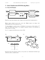
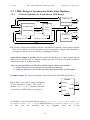
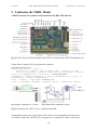
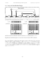
Fig. 2.1-1: Finite-State Machine model. (Signal enable depends in the implementation.)
Moore outputs depend on the state vector only. Mealy outputs can change value
independently of the clock (difficult to test).
The state memory is typically made of n D-flipflops. It can represent a finite number of 2n
states. An infinite state memory is for example a capacitor, because it can memorize an
infinite number of voltages.
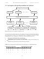
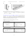
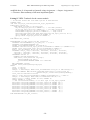
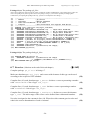
Fig. 2.1-2 compares the different ways to draw a FSM.
(a)
(c)
clk
stimuli
comb.
logic
NextState
memory
state
01
A
D
10
B
reset
00
01
00
(b)
inputs
outputs
0.....0 0
0.....0 1
0.....1 0
0...0
0...1
1...1
...
1.....1 1
E
C
00
10
01
F
11
...
G
0...1
Fig. 2.1-2: Finite-State Machine models (a) Loop model, (b) combinational NextState logic
described as table, (c) bubble model.
-3-