1
INSTRUCTION REF: IN204
ISSUE NO. 3
DATE
13.03.2012
Page 0 of 30
TELEPHONE:
FAX:
SERVICE (44) 01332 875665
SERVICE (44) 01332 875536
INSTRUCTIONS
For the installation
Use
Maintenance
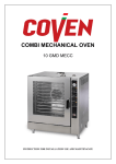
Mixt oven model
6 GMD
INSTRUCTION REF: IN210
ISSUE NO. 1
DATE
13.03.2012
Page 1 of 30
TELEPHONE:
FAX:
SERVICE (44) 01332 875665
SERVICE (44) 01332 875536
Installation diagram - Fig. 1 .................................................................
Instructions for installation ...................................................................
1. Place of installation .........................................................................
2. Installation .......................................................................................
3. Positioning the oven .......................................................................
4. Type of gas .....................................................................................
5. Connection to supply system ..........................................................
6. Water connection .............................................................................
7. Connection to water drain ..............................................................
8. Electrical connection ........................................................................
9. Oven start-up ...................................................................................
Operation of gas valve (and device release) .......................................
10. Controlling the functions ................................................................
11. Transformation for the various types of gas – Fig. 2 ....................
12. Annual maintenance .....................................................................
Calibrations and adjustments ..............................................................
Gas valve - Fig. 3 ................................................................................
Exhaust of gases produced by combustion – Fig. 4 ..........................
Wiring diagram – Fig. 5a ....................................................................
Wiring diagram – Fig. 5b .....................................................................
Wiring diagram key ..............................................................................
Gas burner – Fig. 6 ............................................................................
Technical data – TABLE 1 ..................................................................
Replacing gas parts ............................................................................
Main burner..........................................................................................
Electrodes ..........................................................................................
Gas safety valve .................................................................................
Assembly components of gas valve – Fig. 7 ......................................
Replacing electric parts .......................................................................
Motor ...................................................................................................
Condenser ..........................................................................................
Water inlet solenoid valve ...................................................................
Main switch ..........................................................................................
Safety thermostat ................................................................................
Temperature control probe .................................................................
Electronics board ................................................................................
Instructions for the user – Fig. 8 ..........................................................
Instructions for use ..............................................................................
Maintenance suggestions ....................................................................
Operating suggestions .........................................................................
Cooking suggestions............................................................................
Steam cooking super– Fig. 9 ..............................................................
Mixed cooking – Fig. 9 ........................................................................
Dry convection cooking – Fig. 9 .........................................................
Steam cooking with adjustable temperature – Fig. 9 .........................
Core temperature probe – Operating instructions ...............................
1
page 2
page 3
page 3
page 3
page 3
page 3
page 3
page 3
page 4
page 4
page 4
page 5
page 5
page 6
page 7
page 7
page 8
page 9-10
page 11
page 12
page 13
page 14
page 15
page 16
page 16
page 16
page 16
page 17
page 18
page 18
page 18
page 18
page 18
page 18
page 18
page 18
page 19
page 20
page 21
page 21
page 22
page 23
page 24
page 25
page 26
page 27
INSTRUCTION REF: IN210
ISSUE NO. 1
DATE
13.03.2012
Page 2 of 30
TELEPHONE:
FAX:
SERVICE (44) 01332 875665
SERVICE (44) 01332 875536
Warranty Information …………………………………………………….. page 28-30
Fig. 1
B
E
H
D
A
A.
B.
C.
D.
E.
F.
H.
F
C
2
B
Power cable input
Cooking fumes exhaust pipe
Water input 3/4 " G male
Water release ¾”G male
Combustion fume exhaust
Gas supply pipe ½" G male
Fume reduction water input (on
request) ¾” G male
INSTRUCTION REF: IN210
ISSUE NO. 1
DATE
13.03.2012
Page 3 of 30
TELEPHONE:
FAX:
SERVICE (44) 01332 875665
SERVICE (44) 01332 875536
INSTALLATION INSTRUCTIONS
The manufacturer declares that the equipment complies with the regulations of directives
90/396 EC (Gas equipment); 73/23 EC (Low voltage electric equipment); 89/336 EC
(Electric magnetic compatibility); 89/392 EC (Machines).
The manufacturer cannot be held responsible in case of direct or indirect damages caused
by incorrect installation, use or maintenance.
The serial number label on the right side of the equipment contains all the data needed for
the installation: category, power, consumption, type of gas, etc.
1. PLACE OF INSTALLATION
The equipment must be installed in a well-aired room with air flow, both for gas
combustion and air change as foreseen in standards UNI-CIG 8723 law 46 (5/3/90).
2. INSTALLATION
The installation of the equipment, the adjustments of the safety vale and the repair
interventions can be performed only by a qualified technician, with the proper equipment
and in compliance with the regulations for the safe use of combustion gas 1.n°
1083/6.12.71; safety regulations for gas cookers; accident-prevention regulations;
furthermore the Fire fighting regulations in force must be observed.
3. POSITIONING THE OVEN
Position the equipment on a horizontal surface, well-balanced. The distance between the
wall and the back and side walls of the oven must be of at least 5 cm.
4. TYPE OF GAS
The type of gas the equipment was designed for and originally tested is indicated on the
label on the right side of the equipment. If the required gas is not available, the equipment
must be adapted according to the instructions “TRANSFORMATION FOR VARIOUS
TYPES OF GAS”.
5. CONNECTION TO SUPPLY SYSTEM
Connection to joint ¾” G of the equipment can be either fixed or mobile by interposing an
approved cut-off cock.
The section of the piping must be proportional to the length of the piping itself and the gas
flow of the equipment it musty supply. It must however be installed in compliance with the
UNI-CIG 8723 standards. As regards liquid gas, a pressure regulator with adequate flow
must be positioned on the feeding piping.
If flexible ducts are being used, they must be stainless steel and of the approved type.
After making all connections, a leak finder must be used to verify there are no leaks in the
system.
6. WATER CONNECTION (fig. 1)
Connect oven to water line C and H (on request). Verify that at the end of the operations
there are no leaks. Use only material (pipes, joints, etc.) that complies with the regulations
in force and that in any case does not leave rust build-up.
3
INSTRUCTION REF: IN210
ISSUE NO. 1
DATE
13.03.2012
Page 4 of 30
TELEPHONE:
FAX:
SERVICE (44) 01332 875665
SERVICE (44) 01332 875536
IMPORTANT: A water softener must always be installed upstream of the equipment. The
hardness of water must be lower than 3°F. If an efficient water softener is not installed
there will be scale build-up on the equipment and this could affect its proper operation.
7. CONNECTION TO WATER DRAIN
Connect system to water drain pipe Ø 25 mm. (D fig.1) on the bottom of the oven in the
back part following the indications in the drawing above the drain pipe. Verify that the
connected drain pipe has no bents that exceed the height of the joint itself. Use only
materials (pipes, joints, etc.) compliant with the regulations in force and that in any case do
not leave rust build-up.
8. ELECTRICAL CONNECTION
This oven is manufactured to operate at the voltage indicated on the relevant label. To
access the connection terminal remove the right side of the oven by removing the
fastening screws (A fig. 1). The flexible cable for connection to the mains must not have
characteristics lower than the ones with rubber insulation model H07RN – F and the
section must be the one indicated in TABLE 1. Connection to the electric line must be
made by inserting an automatic switch with adequate capacity (see TABLE 1) with an
opening distance between the contacts of at least 3 mm. It is important to observe the
polarity of the power wires for the correct operation of the oven. If the wires are not
positioned correctly the valve may get blocked. (F=brown, N=blue)
Furthermore, during operation, power supply must not be very different from the value of
the nominal voltage ± 10%.
The equipment must be inserted in an equipotential system, whose effectiveness must be
properly verified according to what is indicated in the regulations in force. Connection must
be made using a screw with this symbol
( EQUIPOTENTIAL) on the rear of the
equipment. The manufacturer cannot be held responsible if this accident-prevention
regulation is not observed.
9. STARTING-UP THE MACHINE (fig. 9)
Remove all protective films.
Open gas
Rotate the main switch 1 to position 1.
Press SET 6. Select the time by rotating knob 8.
Press SET 7. Select the temperature by rotating knob 8.
Notes: If at first attempt the pilot burner does not switch on, verify that:
The gas is open
Aims is on (electric tension on appliance).
Electrode are in a correct position.
It is possible that on first ignition, gas valve may get blocked (RESET warning light is on):
wait for 10 seconds and press RESET knob.
4
INSTRUCTION REF: IN210
ISSUE NO. 1
DATE
13.03.2012
Page 5 of 30
TELEPHONE:
FAX:
SERVICE (44) 01332 875665
SERVICE (44) 01332 875536
OPERATION OF GAS VALVE
Every time the equipment starts running, it runs a self-check of its programs. During
waiting or pre-ventilation time (TW=1,5 sec.) the internal logic controls the amplifier of the
flame signal. A parasite flame signal or a damaged amplifier which indicates the status of
the present flame prevent the equipment from starting up.
At the end of the waiting or pre-ventilation time the gas solenoid valve is powered and the
ON/OFF device is engaged. This starts up the safety time (TS=10 sec.).
If during the safety time the equipment indicates the presence of flame, the ON/OFF
device is blocked.
If the equipment does not indicate any flame signal during the safety time, when the time is
up, the systems stops, the gas solenoid valve is closed, the ON/OFF device is blocked and
the block indicator is engaged (RESET).
If during the safety time the flame blows out, the ON/OFF device is re-engaged within one
second.
UNBLOCKING THE EQUIPMENT
When the equipment shuts down, you must wait at least 10 seconds before trying to start it
up again. Press RESET (17) button.
10. CONTROLING THE FUNCTIONS
Switch on oven in accordance with procedure 9. Set the desired temperature following the
instructions in paragraph “Switching on the machine” point 3. Control flame ignition and the
blowout when the desired temperature is reached.
11. TRANSFORMATION FOR THE VARIOUS TYPES OF GAS
If the equipment must operate with a different type of gas from the one indicated (see
feature label on the right side of the equipment) it is necessary to transform it following the
instructions indicated below.
a. REPLACE BURNER NOZZLES
The nozzles are in the lower right rear part of the appliance. Access the nozzles from
under the frame.
Remove the screw O Fig. 2 that fixes the air control lid Q Fig. 2. Replace the nozzle F
Fig. 6 of the burner.
5
INSTRUCTION REF: IN210
ISSUE NO. 1
DATE
13.03.2012
Page 6 of 30
TELEPHONE:
FAX:
SERVICE (44) 01332 875665
SERVICE (44) 01332 875536
Fig. 2
b. BRUNER AIR CONTROL
Follow this procedure to control the air that goes to the main burner: remove screw O Fig.
5 and position lid Q Fig. 2 as indicated in TABLE 1 (see primary air)
c. FEATURES OF THE BURNER’S FLAME
After adjusting the burner’s air, the flame should have the following characteristics:
Fig. A
Fig. B
Fig. C
Too much air on flame (Fig. A). Light blue flare. The flame tends to move away (blow) or
return (return of flame) with possibility of lighting up at nozzle.
Too little air on flame (Fig. B). Flare with yellow tips. Formation of harmful carbon
monoxide, which causes black smoke that sticks to the combustion chamber. The burner’s
yield is very negative.
Regular flame (Fig. C). Dark blue flare, maximum yield of burner.
ATTENTION: BAD COMBUSTION
Bad combustion may be dangerous for the people around the oven.
CASES OF BAD COMBUSTION
- bad draft (difficult release of exhaust fumes)
- nozzles with wrong holes (bigger) for the gas used (see TABLE 1)
- volume of air under the oven insufficient (see point 3)
6
INSTRUCTION REF: IN210
ISSUE NO. 1
DATE
13.03.2012
Page 7 of 30
TELEPHONE:
FAX:
SERVICE (44) 01332 875665
SERVICE (44) 01332 875536
12. ANNUAL MAINTENANCE
Verify that the stainless steel structure between the burner and the combustion chamber is
integral.
Verify that the mobile connection funnels (h. 50) between the combustion chamber and the
heat exchangers of the cooking chamber are integral.
Verify the conditions of the various gaskets (door, lamp holder, etc.)
CALIBRATIONS AND ADJUSTMENTS (Fig. 3)
Verify, on inlet 8, that inlet pressure is correct :
G20 gas = 20 mbar
G30/31 gas = 30 mbar
After completing it, close tightly screw 10.
7
INSTRUCTION REF: IN210
ISSUE NO. 1
DATE
13.03.2012
Page 8 of 30
TELEPHONE:
FAX:
SERVICE (44) 01332 875665
SERVICE (44) 01332 875536
Fig. 3
KEY
2. Pressure control screw cap
3. Control screw of pressure to main burner
8. Gas pressure outlet entering duct
9. Gas pressure outlet coming out to burner
10. Inlet pressure cap screw
11. Outlet pressure outlet cap screw
12. Driving solenoid valve
13. Main gas outlet to burner
8
INSTRUCTION REF: IN210
ISSUE NO. 1
DATE
13.03.2012
Page 9 of 30
TELEPHONE:
FAX:
SERVICE (44) 01332 875665
SERVICE (44) 01332 875536
EXHAUST OF GASES PRODUCED BY COMBUSTION
ATTENTION: the equipment must have a release collar (A), supplied with oven, that needs
to be assembled correctly as indicated in Fig. 4.
The equipment is type A not designed to be directly connected to an external exhaust,
therefore the equipment releases the combustion substances in an appropriate hood or
similar device, connected to an efficient chimney or directly outside.
Another possibility is that of using an air intake system directly connected outside. The
capacity of the system must not be lower than what is established in point 4.3 of standard
UNI-CIG 8723.
CONNECTING THE RELEASE COLLAR
The release collar must be assembled with the openings in the upper part.
Make sure the chimney is near a filter.
9
INSTRUCTION REF: IN210
ISSUE NO. 1
DATE
13.03.2012
Page 10 of 30
TELEPHONE:
FAX:
SERVICE (44) 01332 875665
SERVICE (44) 01332 875536
EXAMPLE OF UNDER-HOOD INSTALLATION
Fig.4
A
10
INSTRUCTION REF: IN210
ISSUE NO. 1
DATE
13.03.2012
Page 11 of 30
TELEPHONE:
FAX:
SERVICE (44) 01332 875665
SERVICE (44) 01332 875536
Fig. 5a – Wiring diagram
240 V ~
N
F
A
F
B
T
J5 J6
JT1 JT2
T
C
1 2 3 4 5 6 7
D
13 14 15
E
U
EV1
G
H
L
P
2
P
1
M
3
1
R
Q
WHITE
8µƒ
RED
BLACK
1 2 3 4 5 6 7 8 9 1011 12 13 14 15 16
S
19
20
ROSSO
BIANCO
ROSSO
11
M
~
EV2
INSTRUCTION REF: IN210
ISSUE NO. 1
DATE
13.03.2012
Page 12 of 30
TELEPHONE:
FAX:
SERVICE (44) 01332 875665
SERVICE (44) 01332 875536
Fig. 5b – Wiring diagram – Core Temperature Probe (on request)
240 V ~
N
F
A
F
B
T
J5 J6
JT1 JT2
T
C
1 2 3 4 5 6 7
D
13 14 15
E
U
EV1
EV2
G
H
L
P
2
P
1
M
3
1
Q
WHITE
8µƒ
RED
BLACK
M
~
R
1 2 3 4 5 6 7 8 9 10 11 12 1314 15 16
S
19
20
6
4
2
5
3
1
K1
ROSSO
K3
NERO
K4
BIANCO
K2
ROSSO
12 11 10
12
1
2
3
5
INSTRUCTION REF: IN210
ISSUE NO. 1
DATE
13.03.2012
Page 13 of 30
TELEPHONE:
FAX:
SERVICE (44) 01332 875665
SERVICE (44) 01332 875536
WIRING DIAGRAM
A. Terminal box
B. Safety thermostat
C. Main switch
D. Mains indicator
E. Internal light
F. Flame control device
G. Gas safety valve
H. Direct steam solenoid valve
L. Fume reduction solenoid valve (optional)
M. Fume reduction thermostat (optional)
P. Cooking program selector
Q. Motor with condenser
R. Door micro switch
S. Electronic board + probe PT100
T. Fuses
U. RESET warning light
J5. Flame control electrode (ionization)
JT2. Igniting flame electrode
CORE TEMPERATURE PROBE (on request)
K1.
K2.
K3.
K4.
Main switch
Thermostat
Transformer
Alarm
13
INSTRUCTION REF: IN210
ISSUE NO. 1
DATE
13.03.2012
Page 14 of 30
TELEPHONE:
FAX:
SERVICE (44) 01332 875665
SERVICE (44) 01332 875536
Fig. 6
6 GMD
Multigas Burner Cod. 103.2662.00
14
INSTRUCTION REF: IN210
ISSUE NO. 1
DATE
13.03.2012
Page 15 of 30
TELEPHONE:
FAX:
SERVICE (44) 01332 875665
SERVICE (44) 01332 875536
TECHNICAL SPECIFICATIONS
Gas joint
Nominal power (KW.)
Category
Type of installation
Air necessary for combustion m³/h.
: 3/4” G
: 8,5
: II2H3+
: type A
: 17
Connection pressure
: 20 mbar
: 28/37 mbar
: 0,899 m³/h
: 0,655 KG/h
G20 (Methane)
G30/G31 (LPG)
Gas consumption
G20 (Methane)
G30/G31 (LPG)
Gas consumption calculated on calorific value
Lower than (Hi+
) 15°C and 1012 mbar
G20 (Methane)
G30/G31 (LPG)
Main nozzles Ø 1/100
G20 (Methane)
G30/G31 (LPG)
Primary air (See Fig. 5)
G20 (Methane)
G30/G31 (LPG)
Pilot nozzle
G20 (Methane)
G30/G31 (LPG)
: Hi = 34,02 MJ/m³
: Hi = 45,65 MJ/kg
: 210
: 145
: 0 (closed)
:6
: 35 Adjustable
: 20
ELECTRICAL FEATURES
Power KW.
Voltage
Connection cable (H07RN – F)
: 0,350
: 230 VAC
: 3x1 mm²
Water inlet pressure
: 2 bar min.
: 6 bar max.
TABLE 1
15
INSTRUCTION REF: IN210
ISSUE NO. 1
DATE
13.03.2012
Page 16 of 30
TELEPHONE:
FAX:
SERVICE (44) 01332 875665
SERVICE (44) 01332 875536
REPLACING GAS PARTS
Only qualified personnel should carry out this operation!
ATTENTION: before performing any intervention, disconnect the equipment from the
mains and interrupt the gas flow using the gate valve upstream of the equipment.
Remove the right, left and back sides of the equipment.
Main burner (Fig. 6)
1. Remove the anti-reflection panel W.
2. Remove the gas feeding joint A and remove the gas pipe B.
3. Unscrew the 4 screws E Ø 4 on the front of the main burner fixed to the base.
4. Remove the bolts O Ø 5. Remove R. Replace the burner.
5. Screw R back on, put back the screws E and bolts O. Re-connect the gas pipe B and
screw the gas feeding joint back on A. ATTENTION: the gas outlet slots of the burner
must be facing the combustion chamber.
Electrodes (Fig. 6)
Remove the flame ignition electrodes M and flame control electrodes N by removing the
screws that fix them to the front of the main burner. Position the new electrodes in the
proper seats M1 and N1 fix with appropriate screws.
Gas safety valve (Fig. 7)
Disconnect the electric wires of the gas feeding valve. Remove the two screws S to
remove the delivery pipe N from oven, do not separate L and N. Remove the gas outlet
joint P and disconnect the copper pipe B from gas valve block. Remove the eight screws R
that fix the two gas inlet and outlet joints L and M. Replace the valve, position the joints L
and M on the new valve with the relating gaskets and screws. Repeat the operations
indicated above.
Attention !! (Fig. 3)
Verify that outlet pressure regulator is closed: should you remove the cap (2), the screw
(3) must be completely screwed.
16
INSTRUCTION REF: IN210
ISSUE NO. 1
DATE
13.03.2012
Page 17 of 30
TELEPHONE:
FAX:
SERVICE (44) 01332 875665
SERVICE (44) 01332 875536
Fig. 7
17
INSTRUCTION REF: IN210
ISSUE NO. 1
DATE
13.03.2012
Page 18 of 30
TELEPHONE:
FAX:
SERVICE (44) 01332 875665
SERVICE (44) 01332 875536
REPLACING ELECTRIC PARTS
Only qualified personnel should carry out this operation!
ATTENTION: before performing any intervention, disconnect the equipment from the
mains and interrupt the gas flow using the gate valve upstream of the equipment.
Motor
1. Remove the internal deflector of the oven.
2. Remove the central nut Ø 6 of the fan and the socket head screw Ø 4. Slide out the
fan.
3. Remove the back panel of the oven by removing the fastening screws.
4. Disconnect the motor’s feeding wires.
5. Loosen the 6 bolts that fix the motor to the plate. Replace motor.
Condenser
1. Remove the back panel of the oven by removing the fastening screws.
2. The condenser is placed by the motor. Disconnect the feeding wires and those that
connect it to the motor.
3. Replace condenser. ATTENTION: the condenser must have the following features: 500
V 8 µƒ.
Water inlet solenoid valve
1. The solenoid valve is placed in the back part of the equipment
2. Disconnect the wires.
3. Loosen the clamp on the end of the solenoid valve.
4. Disconnect the water feeding pipe.
5. Remove the screws that fix the solenoid valve to the base and replace.
6. Reconnect the wires and make sure they are put in the same position as before.
Main switch
1. Slide out the knob on the command panel
2. Disconnect the power wires.
3. Remove the fastening screws of the control panel
4. Replace part.
Safety thermostat
1. Remove the right side using the fastening screws.
2. Remove the supporting screws of the safety thermostat on the back side of the oven.
3. Remove the safety thermostat.
4. Remove the nuts that hold the deflector in the oven.
5. Remove the screws Ø 4 and remove the thermostat probe and slide it out.
Temperature control probe
Disconnect the probe from the electronic board. Loosen the nut containing the probe.
Remove probe and replace it.
Electronic board
The board is fixed to the control board. Remove the nuts Ø 5 that hold the board.
Disconnect all electric wires. Replace board.
18
INSTRUCTION REF: IN210
ISSUE NO. 1
DATE
13.03.2012
Page 19 of 30
TELEPHONE:
FAX:
SERVICE (44) 01332 875665
SERVICE (44) 01332 875536
INSTRUCTIONS FOR USER
9
8
5
RESET
1
2
c
SUPER
3
SET
c
SET
4
7
Fig. 8
1.
2.
3.
4.
5.
7.
8.
9.
Mains indicator
Main switch
Cooking program selector
Electronic board
RESET knob to unblocking gas valve
Core temperature probe knobs (on request)
Steam exhaust
Gas exhaust
19
INSTRUCTION REF: IN210
ISSUE NO. 1
DATE
13.03.2012
Page 20 of 30
TELEPHONE:
FAX:
SERVICE (44) 01332 875665
SERVICE (44) 01332 875536
INSTRUCTIONS FOR USE
1. We recommend verifying that the installation of the equipment was performed properly;
the manufacturer cannot be held responsible for damages due to wrong installation,
incorrect maintenance, or non compliance with the instructions for use.
2. Before starting up the oven, carefully read the instructions for use. The manufacturer
cannot be held responsible for non compliance with the regulations laid out in this
instructions manual. ATTENTION: the manufacturer cannot be held responsible for any
errors or inaccuracy of this manual due to transcribing or printing errors. Furthermore,
the manufacturer reserves the right to make changes to the equipment deemed
necessary or appropriate, that however do not alter the main features of the equipment.
All the installation, maintenance or repair interventions must be carried out exclusively
by authorized and qualified personnel. The equipment should be controlled every six
months. Therefore we suggest signing a maintenance contract.
3. Starting up the oven (Fig. 9)
- Rotate knob 1 to position 1.
- Set cooking time by pressing SET 6. Set the desired value by rotating the knob 8. To
set the permanent time (always operative) rotate knob 8 to the right until the display
shows P. Attention: during operation the display always shows the time remaining to
the end of the set program.
- Set the temperature by pressing SET 7. Set the desired value by rotating the knob 8.
Attention: during operation the display always shows the real temperature inside the
cooking chamber.
4. Switching the oven off:
After cooking has been completed, bring temperature back to 0. Rotate knob 1 to position
0.
5. Switching the oven off in case of breaks:
In case of breaks or operating problems, switch off the equipment as shown in the
paragraph “Switching the oven off”. Close the gas cock upstream of the equipment.
If the safety thermostat unexpectedly shuts off the oven due to high temperatures inside
the oven, do not switch the oven back on. Contact the assistance service.
20
INSTRUCTION REF: IN210
ISSUE NO. 1
DATE
13.03.2012
Page 21 of 30
TELEPHONE:
FAX:
SERVICE (44) 01332 875665
SERVICE (44) 01332 875536
MAINTENANCE SUGGESTIONS
Do not perform any maintenance or cleaning operation without having first
disconnected the oven from the mains and without interrupting the gas flow using the
valve upstream of the equipment.
Periodically clean the oven to avoid hygiene and operation problems. The equipment
must never be washed with direct flushes or pressure! Clean steel parts with water and
detergents, do not use acid or aggressive substances or abrasive detergents. Do not
use steel wool sponges, which could leave traces of rust.
ATTENTION!!
In some particular area, water can leave on cooking chamber walls, rust deposits.
Walls are not corroded. Coven can suggest you a specific cleaning product as to
remove reported rust deposits.
OPERATING SUGGESTIONS
Coven’ ovens operate through the circulation of hot air. This system is ideal for cooking
pastas, roasts, grill, for baking pastries and thawing frozen foods. Thanks to Coven’
ovens, food looses less weight and volume during cooking. There is a 50% saving on
flavorings.
The hot air must be allowed to circulate above and under the product to cook. Leave
free air tracks at least 4 cm. thick.
Do not use baking sheets with edges higher then necessary. The edges are barriers
against the circulation of air.
Leave some space between one product and another on the same baking rack,
between on chicken and another, etc.
To grill, directly put meat on the grill supplied with the oven. To cook food in containers,
directly use the grids in the side guides instead of the grills.
We suggest using flat cooking sheets for pastries and pizzas.
PRE-HEAT OVEN at the cooking temperature: it is essential to assure good results.
21
INSTRUCTION REF: IN210
ISSUE NO. 1
DATE
13.03.2012
Page 22 of 30
TELEPHONE:
FAX:
SERVICE (44) 01332 875665
SERVICE (44) 01332 875536
COOKING SUGGESTIONS
Roast, game, poultry:
The bigger the pieces to cook the more limited the temperature should be (approx.
180°C). With higher temperatures roasts may be more cooked outside than inside.
Poultry cooks better and faster if open in half or cut in pieces.
To use the sheets, grease with oil or butter and in case of breaded food, keep bread
crumb covering very soft so it does not come off during cooking.
Use humidifier during cooking. The weight loss of meats shall be lower and the food
will cook more evenly.
Lasagna, pastas, etc.:
If you want to grill food, set temperature to 250°C for the last 4 minutes of cooking.
Grilled meat and fish:
Grease the meat or fish before putting it on the grills.
Pizza:
Directly put the pizza on the grills, if the bread base is pre-cooked.
For “Deep dish pizza” cover the pizza baking sheet with an aluminum sheet with holes
on top to let steam out. this is necessary for pizzas that are 1 cm thick.
Pastries:
With Coven’ ovens the temperature to use for pastries is about 30°C lower than with
traditional ovens.
There must be at least 8 cm. between one sheet and the other.
To thaw biscuits, crème, chocolate cakes and sweets in general do not heat the air.
Just switch on the oven and set thermostat to 0.
Regeneration of frozen foods:
Suggested temperature: between 120°C and 130°C. At this temperature bacteria are
eliminated, the containers are not ruined and the food is heated up evenly.
Aluminum containers: pre-heat at 190°C and cook at 140°C
Plastic containers: pre-heat at 130°C and cook at 110°C.
22
INSTRUCTION REF: IN210
ISSUE NO. 1
DATE
13.03.2012
Page 23 of 30
TELEPHONE:
FAX:
SERVICE (44) 01332 875665
SERVICE (44) 01332 875536
SUPER STEAM COOKING (Fresh
vegetables,
boiled
meat
and
regeneration)
10
RESET
b.
Rotate knob 2 to position 5.
d. IMPORTANT: it is not necessary to
set the temperature. The oven is
programmed to reach the temperature of
100°C.
3
SUPER
4
Rotate main switch 1 to position 1.
c.
Set cooking time. Press SET 6 and
set value by rotating the knob 8. To set
the permanent time, rotate the knob 8
until the display shows P. Attention:
during operation, the display always
shows the time remaining to the end of
the set program.
1
c
a.
5
2
Fig. 9
SET
6
SET
7
c
8
9
23
INSTRUCTION REF: IN210
ISSUE NO. 1
DATE
13.03.2012
Page 24 of 30
TELEPHONE:
FAX:
SERVICE (44) 01332 875665
SERVICE (44) 01332 875536
MIXED COOKING CONVECTION +
STEAM (Roasts, vegetables and
regeneration of frozen foods– 4°C)
10
RESET
a. Rotate main switch 1 to position 1.
b. Rotate knob 2 to position 4 and
press button 9 to activate steam.
c. Set cooking time. Press SET 6 and
set value by rotating the knob 8. To
set the permanent time, rotate until
the display shows P. Attention:
during operation, the display always
shows the time remaining to the end
of the set program.
1
5
2
d. Set temperature. Press SET 7 and
set value by rotating the knob 8.
Attention: during operation the
display always shows the real
temperature inside the cooking
chamber.
SET
6
Fig. 9
SET
7
3
c
SUPER
4
c
8
9
24
INSTRUCTION REF: IN210
ISSUE NO. 1
DATE
13.03.2012
Page 25 of 30
TELEPHONE:
FAX:
SERVICE (44) 01332 875665
SERVICE (44) 01332 875536
10
RESET
DRY CONVECTION COOKING (Baked
Pasta, pizza, grilled food)
a. Rotate main switch 1 to position 1.
b. Rotate knob 2 to position 4.
c. Set cooking time. Press SET 6 and
set value by rotating the knob 8. To
set the permanent time, rotate knob 8
until the display shows P. Attention:
during operation, the display always
shows the time remaining to the end
of the set program.
1
SUPER
4
d. Set cooking temperature. Press SET
7 and set value by rotating the knob
8. Attention: during operation the
display always shows the real
temperature inside the cooking
chamber.
3
c
5
2
SET
6
SET
7
c
Fig. 9
8
9
25
INSTRUCTION REF: IN210
ISSUE NO. 1
DATE
13.03.2012
Page 26 of 30
TELEPHONE:
FAX:
SERVICE (44) 01332 875665
SERVICE (44) 01332 875536
STEAM
COOKING
WITH
TEMPERATURE CONTROL FROM
50°C TO 95°C (delicate food, fish,
frozen or fresh shellfish, “sous vide”
cooking)
10
RESET
a. Rotate main switch 1 to position 1.
b. Rotate knob 2 to position 3.
c. Set cooking time. Press SET 6 and
set value by rotating the knob 8. To
set the permanent time, rotate knob 8
until the display shows P. Attention:
during operation, the display always
shows the time remaining to the end
of the set program.
1
3
c
SUPER
4
SET
6
SET
7
c
d. Set temperature. Press SET 7 and
set value by rotating the knob 8.
Attention: during operation the
display always shows the real
temperature inside the cooking
chamber.
5
2
Fig. 9
8
9
26
INSTRUCTION REF: IN210
ISSUE NO. 1
DATE
13.03.2012
Page 27 of 30
TELEPHONE:
FAX:
SERVICE (44) 01332 875665
SERVICE (44) 01332 875536
CORE TEMPERATURE PROBE
Operating instructions
U
P
a. Press knob 1 OFF/ON to switch core temperature probe on.
b. Insert probe into the food.
c. Press P (knob 2) for a second. Display 5 flashes SP1 and a temperature
value. Should you need a different value use knob 3 and 4 to adjust the
temperature, and then press 2. (Should you press for more than a second
keys 3 and 4, you will increase or decrease quickly values).
d. An acoustic signal announces that preset and real temperature inside food
are equal.
ATTENTION : All pre-set functions (main temperature, timer, etc.) are
stopped by acoustic signal.
27
INSTRUCTION REF: IN210
ISSUE NO. 1
DATE
13.03.2012
Page 28 of 30
TELEPHONE:
FAX:
SERVICE (44) 01332 875665
SERVICE (44) 01332 875536
WARRANTY POLICY
The manufacturers warranty is only valid in the UK mainland & Northern
Ireland, Western Isles, Inner Hebrides and Islands are parts only warranty.
All service calls will be carried out between the hours of 8.00am – 5.00pm
Monday to Friday only.
We accept no responsibility for delays in replacing or repairing the equipment
due to circumstances beyond our control.
Your warranty can be immediately invalid if the installation of the equipment
has not been installed in accordance with the manufactures instruction. (See
installation details). Also the miss-use, alteration or unauthorised repairs of the
equipment will invalidate the warranty.
During the warranty period it is at Parrys discretion to repair or replace the
equipment.
Warranty only applies if the equipment has been used in a professional manor
following the manufactures instructions and maintenance guide lines.
The warranty covers defects in the material and components failure only we
are not liable for trading loss, loss of perishable items, water damage, loss due
to injury or fire damage.
WARRANTY REQUEST
Please ensure you have referred to the manufacturers’ instruction before
placing a warranty call. Or contact our warranty department on 01332 875665
for technical assistance. Please ensure you obtain the model number before
calling.
Please ensure you have read the section not covered under warranty to avoid
any unnecessary warranty charges.
If the problem with the machine can not be resolved please contact the
company that supplied you the machine.
(SERVICE CALLS CAN NOT BE PLACED DIRECT WITH PARRY)
28
INSTRUCTION REF: IN210
ISSUE NO. 1
DATE
13.03.2012
Page 29 of 30
TELEPHONE:
FAX:
SERVICE (44) 01332 875665
SERVICE (44) 01332 875536
NOT COVERED UNDER WARRANTY
Fault due to poor maintenance.
Resetting of equipment or circuit breakers.
Abuse of the equipment
Foil should never be used on racks
Blockages eg, drains, condensers, pumps etc
Lime scale related issues
Installed incorrectly
Access arranged for service call and engineer refused access or customer not
there.
No faults with the machine.
Setting up of equipment eg, dishwasher detergents, levelling and setting up of
doors on a 6 burner cooker.
Excessive carbon build up on griddle plates.
Over use of lava rock on the chargrills recommended use by Parry 2kg only.
Faulty electrics – eg, customers plug socket, plug, wiring, junction box fault,
wrong fuse.
Any damages caused by the customer.
Lamps, glass, door gaskets, Perspex, baskets, knobs all perishable items are not
covered.
All of the above are not covered under our warranty policy. Any costs incurred
because of the above will be forwarded to the parties responsible for placing the call.
Failure to pay any warranty charges will result in the customers warranty been put on
hold until the bill has been settled.
Any issues regarding the raised charges should be put in writing to our warranty
department for further investigation.
29
INSTRUCTION REF: IN210
ISSUE NO. 1
DATE
13.03.2012
Page 30 of 30
TELEPHONE:
FAX:
SERVICE (44) 01332 875665
SERVICE (44) 01332 875536
Validate Warranty
It is now even easier to validate your warranty. This can either be done by returning
the warranty card supplied with every product or alternatively you can log onto our
website at
http://www.parry.co.uk/contact-us/product-warranty-registration
and fill out our warranty form and submit it directly to us in seconds.
PLEASE NOTE THAT
FAILURE TO RETURN A
WARRANTY CARD WILL
RESULT IN PARRY BEING UNABLE TO SEND AN ENGINEER TO
CARRY OUT WARRANTY WORK
30