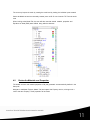
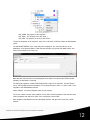
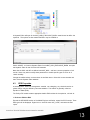
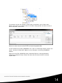
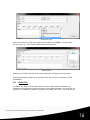
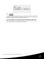
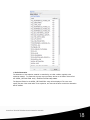
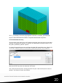
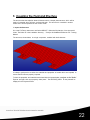
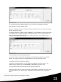
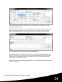
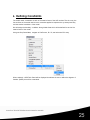
1
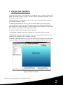
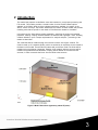
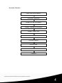
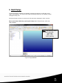
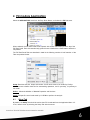
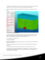
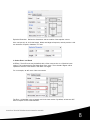
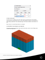
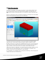
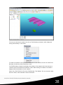
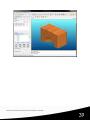
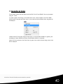
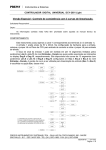
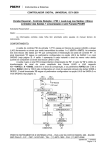
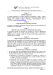
Inventium ○R Tutorial: Fluid-Structure Interaction Module
Copyright © 2010-2013 Engineering Technology Associates, Inc.
This material is a compilation of data and figures from various sources.
Engineering Technology Associates, Inc. assumes no liability or
responsibility to any person or company for direct or indirect damages
resulting from the use of any information contained herein.
Engineering Technology Associates, Inc., ETA, the ETA logo, and
Inventium○R and PreSys○R logos are the registered trademarks of
Engineering Technology Associates, Inc. All other trademarks or names
are the property of their respective owners.
Inventium○R and PreSys○R are both registered trademarks of Engineering
Technology Associates, Inc.
1133 E. Maple Road
Troy, Michigan 48083
USA
www.eta.com
Inventium Tutorial: Fluid-Structure Interaction Module
1
1 PreSys User Interface
The PreSys user interface can be configured in many different ways, for maximum flexibility. The
default user interface is shown in Figure 1. The main areas of the interface are labeled, and will
be referred to in this Tutorial.
The TOOLBAR area is located at the top of the window, and contains selectable icons for all of
the commands available in PreSys.
The DROP DOWN MENUs are at the very top of the window allows users to access every
command through an easy to use drop down menu system. When the Drop Test Module has
been installed with a valid license option, an APPLICATIONS menu will appear in the Drop Down
Menu. The Drop Test Module is accessed through this menu.
The DISPLAY AREA is where all graphical data is displayed.
The COMMAND WINDOW allows users to directly input commands and execute scripts.
The MESSAGE WINDOW displays information about the model and prompts the user if data is
needed, as well as warning or error messages for the user.
The MODEL EXPLORER allows the user to access a great deal of information about the model,
control the display of data, edit the model data and view non-graphical data via ‘card’ images.
Figure 1 default user interface
Inventium Tutorial: Fluid-Structure Interaction Module
2
2 Introduction
This tutorial was prepared to familiarize users with Inventium’s pre and post processing and
FSI module. This module provides a central location for all of the ALE-related options
available in LS-DYNA. While all of the individual entities are available for creation in the
various menus of PreSys, this module streamlines the creation of these models and provides
modeling tools that are specific to the needs of Fluid-Structure Interaction simulation.
In this exercise, the finite element model preparation, specifying the section and material
properties, defining coupling interface between the Eulerian and Lagrangian mesh, boundary
condition definition, input or output requirements for analysis and post – processing of the
results are described.
The model that will be created through this exercise is shown in the figure 2 below. The
model is made up of 2 materials (fluids), which are excited by an explosive source located at
the bottom of the model. These fluids will interact with a structure model. The fluids will be
modeled using the Arbitrary Lagrangian Eulerian (ALE) method, while the structure will be
modeled using traditional finite elements. Coupling will be defined for the fluids and the
structure, in order to transmit the forces from the fluids to the structure.
Figure 2 Model Dimensions (Symmetry about XZ plane)
Inventium Tutorial: Fluid-Structure Interaction Module
3
Procedural Flowchart
Open a New PreSys database
FSI module Application
Coupling the Fluid and Structure
Defining Constraints for the Model
Defining Control Cards
Defining the Simulation Output
LS-DYNA Analysis
Post Processing
Graphical Data
Conclusion
Inventium Tutorial: Fluid-Structure Interaction Module
4
3 Start PreSys
To start the process of modeling the materials, explosive and structure, we will open a new,
empty model database. This can be done simply by starting PreSys from your desktop, doubleclicking the PreSys icon.
All actions that are to be done by the user for this exercise are displayed in Arial in this font.
Start a new PreSys database by opening the PreSys icon. PreSys will open, with a new,
empty database.
Note: In this tutorial the MMTS
unit system is used, with:
Length: (Mm)
Mass: (Ton)
Times: (Second)
Figure 3 Empty Database
Inventium Tutorial: Fluid-Structure Interaction Module
5
4 FSI module Application
Select the APPLICATION menu from the Drop Down Menus, and select the FSI Sub-menu.
When selected, the FSI Task Panel will be opened, with several tabs displayed at the top of the
FSI Task Panel. Each of these tabs help guide the user to defined the needed data to define the
FSI problem.
The FSI Task Panel Tabs are described in detail in the following sections. A brief overview of the
Tabs are provided below:
Setup: Describes the size, shape and number of ALE mesh zones to be created by PreSys.
Allows the user to define mesh size for automeshing operations, and ¼ symmetry, ½ symmetry or
full model.
Define: Allows the definition of Material Properties and Sections.
Cards: FSI-specific control cards used by LS-DYNA to perform the analysis
4.1
Setup Tab
By default, the Setup Tab should be active when FSI is selected from the Application Menu. If it
is not, make it active by selecting the Setup Tab with the mouse.
Inventium Tutorial: Fluid-Structure Interaction Module
6
The Setup Tab is divided into 3 main sections, each providing a way to define the dimensions of
explosive source, the 2 ALE mesh zones and the mesh size and transition mesh.
A graphic is displayed showing the relative position and orientation of the explosive and mesh
zones.
1. Define the ratio of the FIS model
The first option available is the Full / Half / Quarter model options, selectable from a drop down
menu. This will create a full, half or quarter symmetry model. The symmetry will be in the YZ
plane for the half model and the XZ / YZ plane for the quarter model.
For our example, use the Half model.
2. Define the explosive
A general shape may be selected using the radio buttons. Cube, Spherical and Cylindrical shape
explosives are supported.
Dimensions of the shape may be entered. Be sure to consider the model units when defining
these values.
Our example model will use a 40mm by 40mm by 20mm cube-shaped explosive source.
The explosive source can be located Above Zone 1, Below Zone 1, or at a User defined location
in the model. When these options are select, the schematic displayed in the Setup Tab will
change, showing the configuration.
Inventium Tutorial: Fluid-Structure Interaction Module
7
Explosive Dimension: Defines the dimensions and the location of the explosive source.
User can input 40, 40, 20 for the Length, Width, and Height of explosive; and the position is 100
mm below the XY plane, Orientation is Z-axis.
3. Set the Zone1 and Zone2
ALE Zone: The ALE zones may be defined with a Cube cross-section or a Cylindrical crosssection. This is selected using the Shape Drop Down menu. The schematic diagram will be
updated to show the cross-section if this value is changed.
For our example, we will use a Cube cross-section.
The Zone 1 is identified in the schematic, and is the lower section. By default, at least one ALE
Zone is required for the model definition.
Inventium Tutorial: Fluid-Structure Interaction Module
8
The user may select a material using the Material Drop Down menu, The available options are
Soil, Air and Water, By selecting one of these options PreSys will automatically create a material
and assign it to the elements contained in this ALE mesh zone.
For our exercise, please select Soil for this parameter.
The ALE mesh will be automatically created using the dimensions supplied by the user, entered
into the Size field. Enter 240,240, 120 into the Size field. This is the FULL DIMENSION, not the
size of the Half model. PreSys will automatically create the half model based on the full
dimension.
A second ALE Mesh Zone, Zone 2, may be optionally defined in the model. This is active by
default. If a second ALE Mesh Zone is not desired, uncheck the box next to the Zone 2
Dimension.
Zone 2 is located directly above Zone 1, and is required to have the same X and Y dimension
when defining a Cube cross-section. When a Cylindrical cross-section is defined, Zone 2 must
have the same Radius as Zone 1.
Similar to the Zone 1 definition, a material may be selected from the Material Drop Down menu.
For this exercise, please select Air for the material.
For the Size parameter, enter 240, 240 and 40 as the dimensions of the ALE Mesh Zone 2.
4. Set the transition Region
An optional Transition Region will be defined to allow for a locally refined mesh near the explosive
component. The Max ratio defines the ratio of the Element Size to the Transition region mesh
size.
Click the Expand arrow in the right, and set the transition region parameters.
For our example, the no. of regions is 2, and the size of transition region 1 is 100 by 100 by 200,
the Ratio value is 1.0;
The size of transition region 2 is 240 by 240 by 200, and the Ratio value is 1.5.
Inventium Tutorial: Fluid-Structure Interaction Module
9
5. Set the element size
The mesh size can be defined for the ALE mesh zones by using the Element Size parameter.
This controls the nominal element size for mesh. PreSys applies constraints on this parameter to
avoid creating models which are unreasonably large. The minimum element size is limited to 1.0
mm.
Enter a value of 10 as the Element Size for our example.
6. Select APPLY from the bottom of the Setup Tab.
The resulting model will be displayed. Note that the Shade option is active and the Edges option
is active in the image below.
Inventium Tutorial: Fluid-Structure Interaction Module
10
The user may inspect the mesh by rotating the model and by viewing the individual parts created.
Select the Model tab and turn the newly created parts on/off. Do not close the FSI Task tab at this
time.
When looking at the Model Tab, the user will also note that several material, properties and
Equations of State (EOS) were defined along with the elements.
4.2
Review the Materials and Properties.
The default sections and material properties of all part generated are automatically defined in the
Setup tab.
Navigate to the Model Explorer (Model Tab) and expand the Property section, click ing on the +
next to the word Property. Three properties will be listed:
Inventium Tutorial: Fluid-Structure Interaction Module
11
ALE_CORE: the property of the explosive
ALE_SOIL1: The property of the ALE Zone 1
ALE_AIR2: The property of the Air in ALE Zone 2
To view the properties of the explosive, right click on the ALE_CORE and select the Edit Keyword
option.
The KEYWORD EDITOR view of the entity will be displayed. The user may edit any of the
parameters in the Keyword Editor. Fields that are left blank are typically the default values and
need not be modified for this exercise.
Note that each field will have a tool tip displayed at the lower left of the keyword Editor window,
providing the description of the field.
The Setup Tab operation created a SECTION_SOLID entity for the explosive, and ALE Zones 1
and 2. The ELFORM (element formulation) for the explosive part is set to 11, which is the 1 Point
Integration ALE Multi-Material element.
Select CANCEL to close the Keyword editor for the property.
The user is invited to do the same operation for the SOIL and AIR properties. Note that the same
section properties are defined for each of the components of the model.
Next navigate to the Material section of the Model Explorer and right click on the ALE_CORE
material.
Inventium Tutorial: Fluid-Structure Interaction Module
12
A Keyword Editor will open for the MAT_HIGH_E XPLOSIVE _BURN material used to define the
explosive. The options for that material definition may be modified to
Select CANCEL to close the Keyword Editor for the MAT_HIGH_EXPLOSIVE_BURN and open
the Keyword Editor for the SOIL and AIR materials.
Note that the SOIL and AIR are defined with MAT_NULL, and have common properties of soil
and air. Users may wish to modify these parameters to model specific types of soil or air of
certain humidity.
Change the default values to those shown in the fields above. Select OK to save the data and
then close the Keyword Editor windows.
4.3
EOS Properties
A thermodynamic state of a homogeneous material, not undergoing any chemical reaction or
phase change, may be defined by two state variables. This relation is generally called an
Equation of State (EOS).
The PreSys FSI module creates appropriate default EOS entities for the explosive, soil and air.
1. Review or Edit the EOS
Expand the KEYWORD section of the Model Explorer and further expand the EOS section. Three
EOS types will be displayed. Right-click on the EOS name ALE_CORE, and select the Edit
option.
Inventium Tutorial: Fluid-Structure Interaction Module
13
The explosive uses the JWL Equation of State, which is described in the LS-DYNA User’s
Manual. Since there are no defaults values for the EOS, PreSys provides the values for each of
the EOS keywords, shown below.
Review the values there and
select CLOSE to close the keyword editor.
The Soil material uses an EOS_GRUNEISEN form, which is a relationship between pressure and
volume. See the LS-DYNA User’s Manual for more information on the EOS_GRUNEISEN
definition.
Right-click on the EOS_GRUNEISEN entry in the Model Explorer to view the parameters
automatically defined by PreSys. Review the values there and select CLOSE to close the
k eyword editor.
Inventium Tutorial: Fluid-Structure Interaction Module
14
The Air material uses an EOS_LINEAR_POLYNOMIAL equation of state. Please refer to the LSDYNA User’s Manual for more information on the parameters used in this EOS
Right-click on the EOS_LINEAR_POLYNOMIAL entry in the Model Explorer to view the
parameters automatically defined by PreSys. Review the values there and select CLOSE to close
the k eyword editor.
2. Assign EOS to *Part.
Right click the Part: AIR to select Edit Keyword… on the model tree.
Edit Part
Click EOSID on the popped *PART Keyword Editor window to select EOS LINEAR
POLYNOMIAL.
Inventium Tutorial: Fluid-Structure Interaction Module
15
Select EOS Type
Select the created ALE_AIR2 in the popped *EOS LINEAR POLYNOMIAL, and then select
Accept to return to * PART Keyword Editor window and select OK.
Select EOS ID
Relate the ID of EOS to the Part HE and SOLI respectively according to the above steps.
Please note that the EOS type for the Part HE is EOS JWL, and SOLI corresponds to EOS
GRUNEISEN.
4.4
Define Tab
The Define Tab of the FSI Task Panel allows the user to create additional Materials and
Properties and assign those to parts which were not automatically defined in the Setup Tab. For
this exercise, no additional materials or properties are needed. We’ll move on to the Cards Tab.
Inventium Tutorial: Fluid-Structure Interaction Module
16
4.5
Cards Tab
The Cards Tab provides an easy way for the user to create the Control Cards and Keywords that
are needed to complete the set-up of the FSI model. All of the entities that are commonly used for
fluid-structure interaction modeling are included in the Cards Tab.
To create any Keyword listed on the Cards Tab, the user may double click on the name of the
entity. A Keyword Editor for that entity will be displayed. Where default data is provided by LSDYNA, it will be displayed. The user is again referred to the LS-DYNA User’s Manual for details
on each of the parameters used in the various keyword entities.
Inventium Tutorial: Fluid-Structure Interaction Module
17
1. Define Detonation
The detonation of the explosive material is controlled by an initial condition, applied to the
explosive material. To create this, the user must scroll down the list on the Cards Tab and find
the *INITIAL_DE TONA TION entity. Double-click the entity name.
The Keyword Editor for the INITIAL_DE TONA TION entity will be displayed. The user must
specify the part of the model which is the explosive, and the node location at which the detonation
will be initiated.
Inventium Tutorial: Fluid-Structure Interaction Module
18
Select the drop down below the PID field on the INITAIL_DETONATION k eyword. The user may
select from various options.
Select PART from the drop down list, and then PART from the sub-menu. A Part List will be
displayed, where the user may select from the list of select an element of the Part from the
Display Area. Select the part HE from the part list.
The detonation center can be identified by an X, Y, Z location. Click on the button beneath the X,
Y, Z field. This will open a Node/Point selection tool that will allow the user to select an existing
node or point in the model or define a location using an x, y, z coordinate.
Select the center node of the explosive (HE part), at the center of the symmetry plane, at the
bottom.
Inventium Tutorial: Fluid-Structure Interaction Module
19
The x, y, z coordinate of that node will be applied to the field on the INITAIL_DE TONA TION
keyword. Select SAVE and then CLOSE to complete the detonation definition.
2. Define Multi-Material Group
The user needs to also define which ALE materials interact with each other during the simulation.
LS-DYNA accomplishes this definition by defining ALE Multi-Material Groupings, defined on the
ALE_MULTI_MATE RIA L_GROUP keyword.
To create this keyword the user may scroll down the Cards Tab list to find the entry. Double-click
on the entry. A Keyword Editor for the ALE_MULTI_MATE RIAL_GROUP will be displayed.
Select the IDTYPE drop down and select the PART option.
Then, select the SID drop down, selecting the PART ID option. Select the HE part from the list
provided. The PID will be used in the SID field.
Inventium Tutorial: Fluid-Structure Interaction Module
20
Perform this same task for the other ALE materials, using the same procedure for the SOIL and
AIR materials.
Close the FSI Task Panel by selecting OK.
Inventium Tutorial: Fluid-Structure Interaction Module
21
5 Coupling the Fluid and Structure
The structure that the explosive blast will interact with is a simple plate structure, which will be
made of a material which will have nonlinear behavior. This structure is contained in another
model which will be imported into the current model
1. Import the Structure
Go to the FILE drop down menu and Select IMPORT. Select the file plate.dyn, from the tutorial
folder. The folder lie in the installation directory: …\PreSys 2012\e-Manual\Inventium-FSI Training
Manual.
The structure, shown below, is a single component, modeled with shell elements.
It is always good practice to review the materials and properties of models which are imported, to
assure that all units are properly imported.
To view the properties and materials associated with the imported plate, navigate to the Model
Explorer and right click on the property titled “plate”. The SECTION_SHELL for the plate will be
displayed in the Keyword Editor.
Inventium Tutorial: Fluid-Structure Interaction Module
22
The user should note the material thickness (2 mm), and confirm the element formulation.
Select Cancel to close the Keyword Editor.
Navigate to the Material section of the Model Explorer and right-click on the material associated
with the plate (named ‘plate’).
The Keyword Editor for the MAT_PLASTIC_K INEMA TIC will be displayed. Confirm that the units
for the density (RO), Young’s Modulus(E) an Yield Stress (SIGY). The constants provided are
those for a steel material. Users can find more detailed information on this material model by
looking at the LS-DYNA User’s Manual.
Close the Keyword Editor by selecting CANCEL.
The model now has all of the ALE and Lagrangian meshes defined, properties and materials
defined, and is ready to define the coupling between the fluid and structural meshes.
2. Coupling the Fluid and Structure Meshes
To define the interaction between the ALE (fluid) and Lagrangian (structure) meshes, This
interaction will be defined using a CONSTRAINED_LAGRA NGE_IN_SOLID entity.
The user is able to define this from the FSI menu, using the Cards Tab.
Open the Keyword Editor by double-click ing the CONSTRAINED_LAGRANGE _IN_SOLI D entry.
The keyword editor for the entity will open. Enter/select the parameters shown in the image
below.
Inventium Tutorial: Fluid-Structure Interaction Module
23
The key parameters to define are the Master and Slave entities for the interaction. All other
parameters are default values.
Select the SSTYP drop down and select the option for PART SET. Next, select the SLAVE drop
down and the SET_PART option. Once selected, the user can create a SET_PART which
contains the LAGRANGIAN part; the plate, by using the PART button under the SET field.
The user selects SAVE and CLOSE to end that SLAVE definition.
The MASTER definition is the ALE mesh parts. This is defined by selecting the MASTER drop
down and selecting the SET_PART option. As with the Slave definition, select the SET button
and select the 2 ALE mesh parts ALE_SOIL and ALE_AIR. Again, SAVE and CLOSE the
k eyword editor for the Part Set creation.
Select SAVE on the CONSTRAINED_LAGRANGE_IN_SOLI D k eyword editor and the coupling
definition is completed.
Inventium Tutorial: Fluid-Structure Interaction Module
24
6 Defining Constraints
The model needs constraints on each of the exterior faces of the ALE meshes. That is to say, the
free surfaces of the model need to have constraints applied to represent the symmetry boundary
and the exterior boundaries of the model.
We will assign the boundary conditions through Node Sets which will be defined for each of the
exterior faces of the model.
Using the Drop Down Menu, navigate to PreProcess, B.C.S, and select the SPC entry.
When selected, a SPC Task Panel will be displayed that allows the user to define the degrees of
freedom (DOFS) that will be constrained.
Inventium Tutorial: Fluid-Structure Interaction Module
25
We will first define the constraints for the front and rear surface of the model. Select the Type as
BOUNDARY_SPC_NODE.
Tick on the X-Translation to constrained the X freedom. Then click Select Node button.
Input the Spread as 15 in the Select Nodes window, and then pick up any one of nodes in the two
surfaces vertical to the X-axis.
Inventium Tutorial: Fluid-Structure Interaction Module
26
Click Apply button to constrain the X-DOF. The result is shown as the following figure.
Repeat the steps above, and constrain the Z-DOF to the nodes in top and bottom; Constrain the
Y-DOF to the nodes in the left and right. The result is show as the following figures.
Inventium Tutorial: Fluid-Structure Interaction Module
27
Inventium Tutorial: Fluid-Structure Interaction Module
28
7 Defining Control Cards
LS-DYNA simulations require that several control cards be defined. These control cards define
the simulation time, simulation time steps, methods used to deal with model data, such as
hourglass energy. As mentioned earlier, some of the necessary control cards may be defined
using the FSI Cards Tab. There are more general purpose Control Cards that also need to be
defined, which do not appear in the Cards Tab.
To define the control card, right-click the Keyword entry on the Model Explorer, and navigate
down to the CONTROL entry, and select the submenu items.
Select CONTROL_TERMI NATION and enter a termination time of 200e-06 in the ENDTIM field.
Inventium Tutorial: Fluid-Structure Interaction Module
29
Select Save and Close to close the Control_Termination Keyword Editor.
Again, from the CONTROL list, select the CONTROL_TIMESTEP entry. The associated Keyword
Editor will open. This Control Card defines a timestep for the calculation and a scale factor for
reduction in timestep, to achieve a stable solution.
Enter 0.6 in the TSSFAC field, and select SAVE and CLOSE, to close the CONTROL_TIMESTEP
Keyword Editor.
The ALE elements require a special control card, which defines the methods used to make the
ALE fluid calculations, and assure a reasonable solution. These parameters are discussed in the
LS-DYNA User’s Manual.
Carefully enter the values shown in the Keyword Editor image below. The fields that have been
modified from the default values are DCT, NADV, METH, AFAC, and VFACT.
Select SAVE and CLOSE to complete the CONTRAL_ALE card definition.
Inventium Tutorial: Fluid-Structure Interaction Module
30
8 Defining Output
The output from this exercise will be in 2 basic forms – binary data that can be displayed in
PreSys for post processing, and graphical data that will provide us detailed insight into the results
of the simulation.
To request this data using the input file, we will define several DATABASE cards in the model
These DATABASE cards may be defined by accessing the Keyword entry on the Model Explorer.
The primary parameter defined on the DATABSE cards is the time interval at which the requested
data will be written to the file. For each of the DATABASE cards selected, there will be a file
created, containing that specific type of data.
To define the binary data, we will right-click on the Keyword entry in the Model Explorer and
navigate to the DATABASE (ASCII) entry, and select the DATABASE_GLSTAT entry. The
Keyword Editor for the GLSTAT control card will be displayed.
Enter a time interval (DT field) of 1E-6 seconds. The GLSTAT global energy data will be written
every 1E-6 seconds for the duration of the simulation. Select SAVE and CLOSE to complete the
definition of the DATABASE_GLSTAT card.
In a similar manner, create a DATABASE_ELOUT card, again using the DT value of 1E-6 second
for the output interval.
Select SAVE and CLOSE to create the DATABASE_ELOUT card.
The ELOUT database will contain all of the element stresses and strain values for the elements in
the model. Note that this data is created only for elements which are contained in Element Sets.
Inventium Tutorial: Fluid-Structure Interaction Module
31
Both the DATABASE_TRHIS T and the DATABASE_TRACER cards are used to define the
displacement, velocity and stresses of history of a particle in the model.
Select DATABASE_TRHIST from the DATABASE_ASCII menu and enter the DT value of 1E-6
on the DATABASE_TRHIST card.
Select SAVE and CLOSE for each of these cards.
Select DATABASE_TRHIST from the DATABASE menu and enter a location of 0.25,0.005, 0.005
in the x, y, z field of the DATABASE_TRACER card.
The *DATABASE_ELOUT definition, requires a list of the element(s) in which the histories to be
output. This is accomplished by using a DATABASE_HISTORY_SOLID (or _SHELL) to list the
element numbers that will be included in the ELOUT file data.
To create the DATABASE_HISTORY_option card, navigate to the Keyword entry on the Model
Explorer and right-click on the DATABASE entry and select the Create option, and then the
DATABASE_HISTORY option on the submenu.
Inventium Tutorial: Fluid-Structure Interaction Module
32
A Keyword Editor for the DATABASE_HISTORY card will be displayed. To create a listing of
SOLID elements, the user must select the option SOLID from the drop down listing in the Options
field.
To select the individual elements in the model to populate the list, the user must select the
) next to the ID1, ID2, etc. fields. The user may then select the elements from
selection icon (
the Display Area.
Note: another option for output for many elements would be to use the _SOLID_SET option,
which allows the user to define an SET_ELEMENT and refer to it on DATABASE_HISTORY card.
Binary data is defined using the DATABASE_BINARY_option card definitions. We will create just
a single DATABASE_BINARY card for this exercise, D3PLOT. This controls the output of binary
data that is used to visualize the results in a post processor. The content of the D3PLOT file will
vary, depending on the entities in the model. PreSys reads these D3PLOT files easily and allows
the user to create animations of any data contained in that file.
Select DATABASE_BINARY_D3PLOT from the Keyword entry on the Model Explorer. This will
open a keyword editor that allows the user to define the DT parameter of output interval for the
D3PLOT file.
Inventium Tutorial: Fluid-Structure Interaction Module
33
Enter a value of 1E-5 in the DT/CYCL field. This will output the complete model state at that
interval.
This completes all of the input required to set up the simulation. The model may now be exported
and submitted to LS-DYNA for calculation.
Select FILE, and EXPORT from the drop down menu at the top of the PreSys window. The user
will be provided with several options on what to export and how it should be formatted.
Inventium Tutorial: Fluid-Structure Interaction Module
34
The user may select All or a portion of the model to export. Select the default options for each of
the sections of the Export Task Panel, and select OK.
The model will be exported to the file name that you supplied
Inventium Tutorial: Fluid-Structure Interaction Module
35
9 LS-DYNA Analysis
The user may submit the model created in the preceding pages to LS-DYNA for calculation.
When the simulation run is completed, there are certain files created, depending upon the output
defined for the model.
Output files generated by LS-DYNA:
d3hsp (This is a log file in ascii format)
message (This is a log file in ascii format)
The user should check both files for “Warning” and “Error” messages. The description of all
nodes, elements, sections, material, loads, curves and all other data defined in the input file
would be written to d3hsp file.
BINARY output files generated by LS-DYNA, as a result of the DATABASE_BINARY_xxx cards
defined by the user. You should find one or more files with the D3PLOT designation. These are
the binary plot files for animation and graphics. It contains all the results corresponding to the
number of the frequency output defined.
ASCII output files generated by LS-DYNA as requested through the definition of
DATABASE_ASCII_xxx cards. For our exercise we requested:
GLSTAT: Provides details of various energy for graphical variation
ELOUT: Provides details of forces, moments, stress, strain for graphical purposes
TRTHIST: Provide details of position, velocities and stress of the selected particle
Inventium Tutorial: Fluid-Structure Interaction Module
36
10 Post Processing
The results of the simulation can be viewed using PreSys. To read the binary D3PLOT result
files, we Open the files using the FILE/ OPEN command. Navigate to the folder where your
results files are located, and select the D3PLOT file. All D3PLOTS located in that folder will be
read.
When the complete files are read, the model will be displayed in the Display Area, and the Model
Explorer will be populated with Parts for each of the model parts.
The model should look like the image above. Note that the SHADE and ELEMENT EDGES
options are shown, and the model is rotated such that the explosive component is visible.
By default, D3PLOT files are opened with the DEFORM Task Panel active. This panel allows the
user to select the desire simulation steps and will construct an animated image of the steps. To
begin an animation, select the PLAY button in the middle of the DEFORM Task Panel.
Initially, the user will see no deformation, since the ALE mesh will not deform. However, the user
may turn off the ALE mesh parts (part IDs 2 and 3). This will display the Lagrangian shell
elements, and the user will see the deformation of that component.
Go to the MODEL tab on the Model Explorer and expand the PART entry. The user may use the
visibility check boxes to turn off PIDs 2 and 4.
Inventium Tutorial: Fluid-Structure Interaction Module
37
The user can also view the results in the form of Fluid Boundary animations, which display the
moving fluid boundary on the model.
To create an animation of the boundary of the material in fluid meshes, the user can select Fluid
Boundary from the drop down Postprocess menu.
The Fluid Boundary command may display the boundary of the material, which help the user to
check the result of Fluid-Structure Interaction model. When entering the interface, the model is
displayed with the boundaries of each material.
Select VOL_FRACTION #3 in Part list in Fluid Boundary Task Window. The user may then select
the PLAY button, and the animation will be constructed.
Inventium Tutorial: Fluid-Structure Interaction Module
38
Inventium Tutorial: Fluid-Structure Interaction Module
39
11 Graphical Data
The simulation output that was written to the GLSTAT, ELOUT and TRHIST files may be plotted
using X-Y curves.
To create a graph of the energy in the model versus time, we will navigate to the FILE / NEW
GRAPH option using the drop down menu. A new model tab will be opened where the graph will
be displayed.
LOAD the GLSTAT result file using the Open File icon. All of the data available for graphing will
be displayed. Select ENERGY and then the INTERNAL ENERGY component.
Select PLOT at the bottom of the Task Panel. A graph of the model’s internal energy versus time
will be displayed.
Inventium Tutorial: Fluid-Structure Interaction Module
40
Note: Additional post processing may be performed on the data generated from the analysis.
Please refer to the PreSys Tutorial: Inventium PreSys R2 Post Processing Tutorial for additional
information on post processing features.
Inventium Tutorial: Fluid-Structure Interaction Module
41
12 Conclusion
This concludes the training overview of the FSI module and post processing using Inventium.
The user should now have basic skills required to generate the Finite element model, set up the
analysis and extract the necessary results. The user should also refer to the PreSys and VPG
manuals and LS-DYNA User’s Manual for more details.
Inventium Tutorial: Fluid-Structure Interaction Module
42