1
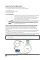
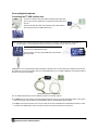
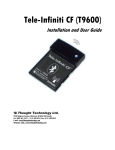
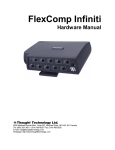
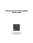
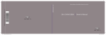
ProComp2
User Guide and Hardware Manual
Thought Technology Ltd.
8205 Montreal/Toronto Blvd., Suite 223, Montreal West, QC H4X 1N1 Canada
Tel: (800) 361-3651 • (514) 489-8251 Fax: (514) 489-8255
E-mail: [email protected]
Webpage: http://www.thoughttechnology.com
The Manufacturer:
Thought Technology Ltd.
8205 Montreal/Toronto Blv., Suite 223
Montreal West, Quebec, Canada
H4X 1N1
Product Name:
ProComp2 Biofeedback System
Product No:
SA7400
Device Name:
PROCOMP2 BIOFEEDBACK UNIT
Device No:
SA7400
EC
REP
EMERGO EUROPE
Molenstraat 15, 2513 BH,
The Hague, The Netherlands
Tel: +31.70.345.8570
Fax: +31.70.346.7299
ProComp2 User Guide and Hardware Manual
CLASSIFICATION
Type BF Equipment
Internally pow ered equipment
Continuous operation
Read Instruction Manual.
CAUTION
US Federal Law restricts this device to sale by or on order of licensed health care practitioners.
WARNING
Do not operate active sensors w ithin 10 feet (3m) of an operating cellular phone, similar radio transmitting
device, other pow erful radio interference producing sources such as arc w elders, radio thermal treatment
equipment, x-ray machines or any other equipment that produces electrical sparks.
All encoders are totally isolated from line (110 or 220VAC) pow er due to battery operation and fiber optic
connections to computers. How ever, many hospitals and the FDA require that computers, printers and any
other equipment used w ith medical devices be electrically isolated from line voltage to UL or CSA medical safety
standards.
Do not connect inputs or outputs of the encoder or sensors to line pow ered devices, except through the fiber
optic cable.
The PC used w ith ProComp2 must be placed outside the patient/client environment (more than 3 meters or 10
feet) or the PC must comply w ith EN60601-1.1 (system safety).
After use, the disposable electrodes may be a potential biohazard. Handle and, w hen applicable, dispose of
these materials in accordance w ith accepted medical practice and any applicable local, state and federal law s
and regulations.
To diminish the risk of spreading communicable diseases, alw ays use good hygiene practices w ith reusable
EMG electrodes, particularly if abrasive substances are used. In all cases, refer to your facility's infection
control procedure.
Do not use in the presence of a flammable anesthetic mixture w ith air or w ith Oxygen or Nitrous Oxide.
Not to be immersed in w ater.
Take care in arranging patient and sensor cables to avoid risk of patient entanglement or strangulation.
The operator is responsible for ensuring the safety of any devices controlled or triggered by Infiniti equipment or
softw are, or by any softw are or hardw are receiving data from Infiniti equipment. Infiniti equipment must not be
configured or connected in such a w ay that failure in its data acquisition, processing or control functions can
trigger patient feedback stimulus that poses an unacceptable level of risk.
Use of any equipment in a biofeedback context should be immediately terminated upon any sign of treatmentrelated distress or discomfort.
Not to be connected to a patient undergoing MRI, Electro surgery or defibrillation.
ATTENTION
To prevent static discharge from damaging the sensor and/or encoders, use anti-static mats or sprays in your
w orking area. A humidifier may also be used to help prevent static environments by conditioning hot, dry air.
Not for diagnostic purposes. Not defibrillator proof. Not for critical patient monitoring.
To prevent voiding w arranty by breaking connector pins, carefully align w hite guiding dot on sensor plug w ith
slot on sensor input.
Make sure to remove electrodes from sensor snaps immediately after use.
Apply conductive gel only to electrodes. Never put gel directly on sensor snaps.
ProComp2 User Guide and Hardware Manual
i
Sharp bends or w inding the fiber optic cable in a loop smaller than 4 inches (10cm) may damage the cable.
A fiber optic cable not fully pushed into its receptacle may cause the unit not to operate. Make sure that both
ends of the cable are fully inserted into their receptive jacks and the nut is tightened firmly.
Do not plug third party sensors directly into instrument inputs. Plug only Thought Technology active sensor cable
connectors into instrument inputs. All EMG electrodes and third party sensors must be connected to active
sensors, either directly or through an adapter.
Remove batteries w hen the device is not being used for extended period of time. Please dispose of battery
follow ing national regulations.
INTENDED PURPOSE
Biofeedback, relaxation and muscle re-education purposes.
CONTRAINDICATIONS
None.
NOTE
No preventative inspections required. Maintenance must be performed by qualified personnel.
The supplier w ill make available, upon request, circuit diagrams, component parts lists and description or other
information required for the repair of product by qualified personnel.
If a fiber optic or patient cable is damaged or breaks, please replace it.
MAINTENANCE AND CALIBRATION
Wipe encoder w ith a clean cloth.
STORAGE
Store in its original case.
Temperature
-23C – +60C
Humidity (non-condensing)
10% – 90%
Atmospheric pressure
700 – 1060 KPa
TRANSPORTATION
Transport in its original case.
Temperature
-23C – +60C
Humidity (non-condensing)
10% – 90%
Atmospheric pressure
700 – 1060 KPa
SA7420 Rev. 7
© 2003-2013 Thought Technology Ltd.
ProComp2 User Guide and Hardware Manual
ii
Table of Contents
About the ProComp2 Encoder
1
General description
1
Connecting the hardware
2
Connecting the TT-USB interface unit
2
Connecting sensor cables
3
General instructions for use
3
Electrical interference
3
After use
3
Changing the batteries
4
Opening the compartment
4
Polarity
4
Closing the compartment
4
Monitoring the battery level
4
Caring for the fiber optic cable
4
Winding or bending
4
Cutting the fiber optic cable
4
Impedance checking
5
Checking impedance
5
Hardware Specifications
6
ProComp2 (SA7400)
6
Infiniti hardware copyright notice
7
Reference
8
Warranty
8
Optional extended warranty
8
Contacting Thought Technology
8
Placing orders
8
Technical support
8
ProComp2 User Guide and Hardware Manual
iii
Returning equipment for repair
Repair return form
ProComp2 User Guide and Hardware Manual
8
10
iv
About the ProComp2 Encoder
The ProComp2 (SA7400) comes with the following components.
One two-channel ProComp2 encoder unit, with one integrated EEG sensor.
One TT-USB interface unit.
A supply of fiber optic cable (15' cable).
One EEG extender cable.
General description
The ProComp2 encoder is a two-channel, multi-modality physiological monitoring
device for use with biofeedback software applications, such as Thought
Technology's BioGraph Infiniti software with an Application Suite (ProComp2 also
works with other software). The ProComp2 can be used for data acquisition,
physiological signal monitoring and biofeedback.
The ProComp2 has four protected pin input connectors on its front panel. Because
of their disposition, only two sensors can be connected at a time. Inputs A and B
sample data at 256 samples per second. Input A incorporates an internal EEG
sensor within its circuitry, and is dedicated to recording EEG. Inputs C and D
sample at 32 samples per second.
Sensors, connected to the ProComp2 encoder by protected pin cables, measure biofeedback responses and
send the raw signals to the encoder. Depending on the software being used, these may include sensors
specialized for electromyography (EMG), electroencephalography (EEG), electrocardiography (EKG), skin
temperature, skin conduction, respiration, or blood volume pulse (BVP). The document Sensors and
Accessories SA7511 contains a complete list of Thought Technology sensors that can be used with the
ProComp2.
The ProComp2 encoder samples the incoming signals, digitizes, encodes, and transmits the sampled data to
the TT-USB interface unit. A fiber optic cable is used for transmission to the TT-USB, providing maximum
freedom of movement, signal fidelity, and electrical isolation.
The TT-USB interface unit is connected to one of the host computer's USB ports. It receives the data arriving from
the ProComp2 in optical form and converts it into the USB format to communicate with the software.
Note: Some hardware features may not be supported by all software programs. Consult the software manual for a full list of
features supported.
Some software programs will not function with a TT-USB, but require use of a PRO-SB in its place.
Unconnected hardw are com ponents
ProComp2 User Guide and Hardware Manual
1
Connecting the hardware
Connecting the TT-USB interface unit
Insert one end of the fiber optic cable carefully into the fiber optic
port on the encoder. Tighten the nut gently so that the cable won't
slip out.
Do the same with the other end of the fiber optic cable and the
fiber optic port of the TT-USB interface unit.
Note: The fiber optic connectors may break if they are hit directly, for instance, if the encoder falls onto the floor. To
prevent damage, it is recommended to use the encoder belt clip to fasten it to the client or to a chair.
Insert the small connector of the USB cable into the USB
port on the TT-USB interface device.
Insert the large connector of the USB cable into the USB
port of your PC.
USB ports on a PC are generally located at the back of the base unit. You may also find a USB port at the front of
your base unit; you can connect the other end of the USB cable to it. On a laptop, USB ports are usually located at
the side or the back of the laptop.
Connected hardw are com ponents
The TT-USB interface device has two additional optional connection options.
The Switch is a 3.5mm jack for connecting external devices such as a muscle stimulation device. This can be
used, for example, with the Switch control feedback option in the BioGraph Infiniti software.
The Sync connector permits the use of a sync cable to connect an additional TT-USB interface device in order
to synchronize data between units. The Sync connector can also be used for an event input.
ProComp2 User Guide and Hardware Manual
2
Connecting sensor cables
Numerous regulatory bodies (such as the FDA in the USA) have adopted safety
specifications requiring that all medical products for physiological monitoring be
manufactured with electrode leads that have no exposed metal plugs.
For this reason, the ProComp2 encoder and Thought Technology sensors use
specially designed connectors that have all metallic surfaces recessed within the
plastic casing. These connectors, with protected pins, require care when you are
plugging and unplugging sensor cables to the encoder or an extender cable to the
sensor head.
When connecting a sensor cable to the ProComp2, make sure to properly line up the
guiding dot on the top of the plug with the notch in the encoder input socket, as
shown in the illustration. Forcing the plug into the jack in any other position may
damage your equipment.
General instructions for use
1. Plug the sensors you wish to use into the input connectors on the front of the encoder and connect any
required extender cables, making sure to use clean electrodes, onto the sensor head.
2. If appropriate, clean the skin area where the electrodes will be placed.
3. Place the encoder on or near the patient, to avoid signal degradation.
4. Turn the encoder power switch ON and check that the blue power indicator is lit. If it is not, turn the device OFF
and check the condition and orientation of the batteries. If the blue indicator starts to flash, there is
approximately 20-30 minutes of use left in the batteries (if using alkaline batteries). Keep spare batteries
nearby.
5. Start the software program as instructed in the user's manual.
6. After the session, turn the encoder power OFF and disconnect all electrodes.
Note: Thought Technology encoders, sensors, and interface units carry parts that may be damaged by static electric
discharges. Exercise care when handling this equipment in static-prone environments. Thought Technology
instruments are not warranted against damage caused by static discharge. In dry areas or carpeted areas, use antistatic mats or sprays and condition the air by using humidifiers.
Electrical interference
When performing a biofeedback session, avoid placing the ProComp2 near the computer, display monitor or any
other electrical device, where it can be exposed to electromagnetic fields. Try to keep the encoder within the
client's natural electrical field. In most cases, you can do so by fastening the belt-clip to the client's waist.
After use
As a general rule, remove electrodes from the sensor heads and extender cable leads when you are done using
your equipment. Many electrodes are coated with a very conductive substance that can cause the sensor's metal
parts to corrode if they are left in contact with it for long periods of time. Be careful, when unsnapping electrodes,
not to damage the wires. Avoid twisting and pulling on the wires by holding the sensor head or the extender
cable's rounded snap.
ProComp2 User Guide and Hardware Manual
3
Changing the batteries
Opening the compartment
The ProComp2 device requires a single AA, 1.5 volt, alkaline battery. Looking at the
underside of the ProComp2 device, you will see a small panel with engraved arrow (>>>)
marks.
To open it, place your thumb on the arrows and push out, towards the side. The door
should snap open. To remove the battery, tap the ProComp2 against your hand, until the
battery slides out.
Polarity
Place one AA battery in the slot, observing the correct battery polarity as indicated in the compartment.
Closing the compartment
Slide the door back into the ProComp2 case, gently pushing it in until you feel the click of the locking
mechanism.
Monitoring the battery level
Since each sensor draws a small amount of power from the battery when connected to the ProComp2, it is
better to connect only the sensors that are going to be used for a session before you start recording; this will
ensure maximal battery life. Most Thought Technology software applications will display a battery power
indicator; we recommend that you replace the batteries as soon as this indicator falls below about 50% of the
battery power.
Important:
Remove dead batteries promptly to prevent corrosion damage.
Caring for the fiber optic cable
A fiber optic (FO) cable is used for transmitting the sensor data to the
computer. Although this technology provides maximal electrical isolation,
signal fidelity and freedom of movement, some care has to be taken when
handling the fiber optic cable, as it is much less flexible than a regular
electric wire.
Winding or bending
It is most important to avoid bending the cable too sharply. In a FO cable, information travels as light impulses.
Any kink along the optical fiber may partially or completely block the light's path and, thus, interrupt the flow of
sensor information to the computer. When using your system, try to keep the extra length of cable wound in a
loose loop no smaller than about 4 inches (10 cm) in diameter.
Cutting the fiber optic cable
If you have problems establishing a good connection, there may be a break in the fiber optic cable. Follow these
directions to remove the damaged segment.
ProComp2 User Guide and Hardware Manual
4
Holding it lightly between your thumb and index fingers, feel along the whole length of the cable, searching for
kinks. If you do find a break, the optic fibers may be too damaged to let the light pass properly. Use a sharp box
cutter blade to slice the FO cable into shorter unkinked segments. Do not use scissors, because they make a Vshaped cut that may impede the data stream.
Impedance checking
The integrated EEG sensor (Input A of the ProComp2 encoder) does not have impedance-checking capabilities.
If you have an EEG-Z sensor from Thought Technology and software that has a compatible impedance checking
function (such as BioGraph Infiniti), you can check the impedance by following these steps.
Checking impedance
1. Place the electrodes on the client and connect the EEG extender cable to the EEG-Z sensor.
2. Connect the EEG-Z sensor to Input B of the ProComp2 encoder.
3. Start the software, choose the impedance checking channel set, and start a session.
4. Do not start recording. Access the impedance checking function from the Options menu.
5. Disconnect the EEG-Z sensor from Input B and then reconnect it. The sensor goes into impedance checking
mode and the window displays impedance values.
6. If necessary, adjust the electrodes on the client and then repeat the preceding step.
7. When you are satisfied with the displayed values, close the impedance check window and end the impedance
checking session.
8. Connect the EEG extender cable to Input A of the ProComp2 encoder, and remove the EEG-Z sensor.
9. Choose the appropriate channel set and start the recording session.
Note: The sampling rates used by the ProComp2 are not compatible with the MyoScan-Z sensor. Impedance checking
cannot be performed for MyoScan-Z sensors.
ProComp2 User Guide and Hardware Manual
5
Hardware Specifications
ProComp2 (SA7400)
Approx. size
2 ½" x 2 3/16" x 5/8" (64mm x 56mm x 16mm)
Approx. w eight w /o batteries
40 g
Input im pedance (Input A)
1,000,000 mΩ
Input im pedance (Input B, C, D)
2 mΩ
Resolution (Input A only)
=0.1 µV RMS
Signal input range (Input A)
0-200 µV RMS
Signal input range (Input B, C, D)
2.0V – 3.6V
CMRR (Input A)
=-130 @ 2 Hz to 45 Hz
Channel bandw idth
0 Hz – 45 Hz
Sam ple rate/channel (A, B)
200 or 256 samples/second
Sam ple rate/channel (C, D)
20 or 32 samples/second
Supply voltage
1.0V – 1.6V
Current consum ption
75 mA - 150 mA @ 1.5 V
Battery life (Alkaline)
10 Hours (minimum)
Low battery w arning
1.1 V ± 0.2 V
Data output protocol
19.2 or 38.4 Kbaud, 8 Bits, 1 Stop, No Parity
Analog to digital conversion
13 bits
System accuracy
+/- 5%
Note: ProComp2 and its sensors are sensitive electronic instruments and should be handled as such. Be especially
careful to avoid both pulling on the electrode cable and getting moisture or electrode gel on the sensor snaps. If
necessary, wipe the surface with a damp cloth or use a moistened Q-tip to remove gel from inside the sensor snaps.
Wipe with a dry cloth.
ProComp2 User Guide and Hardware Manual
6
Infiniti hardware copyright notice
This hardware contains proprietary embedded software code, which is the property of Thought Technology Ltd.; it
is provided under a license agreement containing restrictions on use and disclosure and is also protected by
copyright law. Reverse engineering of the software or the resulting output data stream is prohibited.
Due to continued product development the embedded software may change without notice. The information and
intellectual property contained herein is confidential between Thought Technology Ltd. and the client and
remains the exclusive property of Thought Technology Ltd.
If you find any problems in the documentation, please report them to us in writing. Thought Technology Ltd. does
not warrant that this document is error-free.
No part of this publication may be reproduced, stored in a retrieval system, or transmitted in any form or by any
means, electronic, mechanical, photocopying, and recording or otherwise without the prior written permission of
Thought Technology Ltd.
ProComp2™, ProComp5 Infiniti™, ProComp Infiniti™, FlexComp Infiniti™, BioGraph® are trademarks of
Thought Technology Ltd.
© Copyright Thought Technology 2003-2013
ProComp2 User Guide and Hardware Manual
7
Reference
Warranty
The ProComp2 system and all equipment including optional items are guaranteed to be free from defects in
material and workmanship for 1 year from the date of purchase.
In the unlikely event that repair is necessary, call Thought Technology Ltd. to receive a Return Authorization. Then
send the unit back by a traceable method – Thought Technology will not be responsible for items not received.
We will repair or replace your unit(s) free of charge.
This warranty does not apply to damage incurred through accident, alteration, or abuse, nor to sensor damage
created by static electricity. Do not use this equipment in dry, static area unless using an anti-static mat or antistatic spray on carpeted areas.
Thought Technology may refuse to honor this warranty if the tamper-evident seal located in the battery
compartment is broken.
Important:
Remove dead batteries promptly to prevent corrosion damage.
Optional extended warranty
Please contact Thought Technology Ltd. for further details.
Contacting Thought Technology
Placing orders
Outside USA
Tel:
(514) 489-8251
Fax:
(514) 489-8255
In USA Toll-Free
Tel:
1-800-361-3651
E-mail:
[email protected]
Technical support
For technical support please refer to the Thought Technology Ltd website at www.thoughttechnology.com for
frequently asked questions. If your support issue is not covered please e-mail or call technical support at the
telephone number below.
E-mail:
[email protected]
Tel:
(514) 489-8251
Returning equipment for repair
Before returning the equipment, first please contact our service department and get an authorization number (RA
number).
Tel (USA and Canada): (800) 361-3651, ext 130
Tel (Overseas):
+1 514-489-8251, ext 130
E-mail:
[email protected]
Then fill in the return form (the form can be found on the next page). You must provide a detailed description of
the problem you are experiencing, and your telephone/fax number and e-mail.
The unit(s) must be sent postage prepaid and insured, with proof of purchase to one of the addresses on the
following page.
ProComp2 User Guide and Hardware Manual
8
All customs and duties charges will be billed to the customer if incurred by sending the unit to the wrong
address.
In the USA, ship insured to:
Thought Technology Ltd.
Cimetra LLC
8396 State Route 9
West Chazy, New York
12992 USA
In Canada, ship insured to:
Thought Technology Ltd.
8205 Montreal/Toronto Blvd., Suite 223
Montreal West, Quebec
Canada H4X 1N1
For overseas:
Package must be marked with “Broker: Livingston International – 133461”.
Ship insured to:
Thought Technology Ltd.
8205 Montreal/Toronto Blvd., Suite 223
Montreal West, Quebec
Canada H4X 1N1
ProComp2 User Guide and Hardware Manual
9
Repair return form
Be sure to call for authorization before returning any equipment!
Copy and complete this form and include it with the unit(s).
Include a copy of original invoice and return to the address in the Returning equipment section.
Nam e
Com pany
Address
Phone No.
Fax No.
Date Purchased
From Whom
Model Nam e
Serial No.
Problem
ProComp2 User Guide and Hardware Manual
10