1
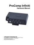
FlexComp Infiniti
Hardware Manual
Thought Technology Ltd.
8205 Montreal/Toronto Blvd., Suite 223, Montreal West, QC H4X 1N1 Canada
Tel: (800) 361-3651 • (514) 489-8251 Fax: (514) 489-8255
E-mail: [email protected]
Webpage: http://www.thoughttechnology.com
The Manufacturer:
Thought Technology Ltd.
8205 Montreal/Toronto Blvd., Suite 223
Montreal West, Quebec, Canada
H4X 1N1
Product Name:
FlexComp Infiniti System
Product No:
T7550M, T7555
Device Name:
FLEXCOMP INFINITI ENCODER
Device No:
SA7550
EC
REP
EMERGO EUROPE
Molenstraat 15, 2513 BH,
The Hague, The Netherlands
Tel: +31.70.345.8570
Fax: +31.70.346.7299
FlexComp Infiniti Hardware Manual
CLASSIFICATION
Type BF Equipment
Internally powered equipment
Continuous operation
Read Instruction Manual.
CAUTION
US Federal Law restricts this device to sale by or on order of licensed health care practitioners.
WARNING
Do not operate active sensors within 10 feet (3m) of an operating cellular phone, similar radio transmitting device, other
powerful radio interference producing sources such as arc welders, radio thermal treatment equipment, x-ray machines
or any other equipment that produces electrical sparks.
All encoders are totally isolated from line (110 or 220VAC) power due to battery operation and fiber optic connections to
computers. However, many hospitals and the FDA require that computers, printers and any other equipment used with
medical devices be electrically isolated from line voltage to UL or CSA medical safety standards.
Do not connect inputs or outputs of the encoder or sensors to line powered devices, except through the fiber optic cable.
The PC used with FlexComp Infiniti must be placed outside the patient/client environment (more than 3 meters or 10
feet) or the PC must comply with EN60601-1.1 (system safety).
After use, the disposable electrodes may be a potential biohazard. Handle and, when applicable, dispose of these
materials in accordance with accepted medical practice and any applicable local, state and federal laws and
regulations.
To diminish the risk of spreading communicable diseases, always use good hygiene practices with reusable EMG
electrodes, particularly if abrasive substances are used. In all cases, refer to your facility's infection control procedure.
Do not use in the presence of a flammable anesthetic mixture with air or with Oxygen or Nitrous Oxide.
Not to be immersed in water.
Take care in arranging patient and sensor cables to avoid risk of patient entanglement or strangulation.
The operator is responsible for ensuring the safety of any devices controlled or triggered by Infiniti equipment or software,
or by any software or hardware receiving data from Infiniti equipment. Infiniti equipment must not be configured or
connected in such a way that failure in its data acquisition, processing or control functions can trigger patient feedback
stimulus that poses an unacceptable level of risk.
Use of any equipment in a biofeedback context should be immediately terminated upon any sign of treatment-related
distress or discomfort.
Not to be connected to a patient undergoing MRI, Electro surgery or defibrillation.
ATTENTION
To prevent static discharge from damaging the sensor and/or encoders, use anti-static mats or sprays in your working
area. A humidifier may also be used to help prevent static environments by conditioning hot, dry air.
Not for diagnostic purposes. Not defibrillator proof. Not for critical patient monitoring.
To prevent voiding warranty by breaking connector pins, carefully align white guiding dot on sensor plug with slot on
sensor input.
Make sure to remove electrodes from sensor snaps immediately after use.
Apply conductive gel only to electrodes. Never put gel directly on sensor snaps.
Always use electrodes between the subject and the sensor.
FlexComp Infiniti Hardware Manual
i
Sharp bends or winding the fiber optic cable in a loop smaller than 4 inches (10cm) may damage the cable.
A fiber optic cable not fully pushed into its receptacle may cause the unit not to operate. Make sure that both ends of
the cable are fully inserted into their receptive jacks and the nut is tightened firmly.
Do not plug third party sensors directly into instrument inputs. Plug only Thought Technology active sensor cable
connectors into instrument inputs. All EMG electrodes and third party sensors must be connected to active sensors,
either directly or through an adapter.
Remove batteries when the device is not being used for extended period of time. Please dispose of battery following
national regulations.
INTENDED PURPOSE
Biofeedback, relaxation and muscle re-education purposes.
CONTRAINDICATIONS
None.
NOTE
No preventative inspections required. Maintenance must be performed by qualified personnel.
The supplier will make available, upon request, circuit diagrams, component parts lists and description or other
information required for the repair of product by qualified personnel.
If a fiber optic or patient cable is damaged or breaks, please replace it.
Due to the essential performance and intended use of the device, testing for immunity to electromagnetic disturbances
was not required and was not performed. The device may be susceptible at levels below IEC60601-1-2 immunity test
levels.
The operator must be familiar with typical characteristics of signals acquired by this equipment, and be able to detect
anomalies in the acquired signal that could interfere with treatment effectiveness. Depending on the importance of signal
integrity, it may be advisable to continuously monitor the raw signals, in time and/or frequency domain, while the device
is being used for biofeedback or other purposes. If anomalies are observed on acquired signals, and if you suspect a
problem with electromagnetic interference, contact Thought Technology for a technical note on identification and
remediation.
MAINTENANCE AND CALIBRATION
Wipe encoder with a clean cloth.
Factory testing and calibration ensure equipment accuracy and frequency response. The user may invoke a selfcalibration function that will recalibrate certain device parameters (see the Self-Calibration section of this manual).
Contact Thought Technology for factory recalibration if necessary.
STORAGE
Store in its original case at up to 90% humidity / 85°F (30°C).
TRANSPORTATION
Transport in its original case.
FlexComp Infiniti Hardware Manual
ii
Guidance and manufacturer's declaration – electromagnetic emissions
The Infiniti system is intended for use in the electromagnetic environment specified below. The customer or the user of the Infiniti
system should assure that it is used in such an environment.
Emissions test
Compliance
Electromagnetic environment – guidance
RF emissions
CISPR 11
Group 1
The Infiniti system uses RF energy only for its internal function.
Therefore, its RF emissions are very low and are not likely to
cause any interference in nearby electronic equipment.
RF emissions
CISPR 11
Class B
Harmonic emissions
IEC 61000-3-2
Not applicable
Voltage fluctuations/flicker
emissions
IEC 61000-3-3
Not applicable
The Infiniti system is suitable for use in all establishments,
including domestic establishments and those directly
connected to the public low-voltage power supply network that
supplies buildings used for domestic purposes.
SA7560 Rev. 4
© 2003-2011 Thought Technology Ltd.
FlexComp Infiniti Hardware Manual
iii
Table of Contents
About the FlexComp Infiniti Encoder
1
General description
1
Connecting the hardware
2
Connecting the TT-USB interface unit
2
Connecting sensor cables
2
Setting the communication protocol
3
General instructions for use
3
Electrical interference
4
After use
4
Changing the batteries
4
Opening the compartment
4
Polarity
4
Closing the compartment
4
Monitoring the battery level
4
Caring for the fiber optic cable
4
Winding or bending
4
Cutting the fiber optic cable
5
Self-calibration
5
Running a self-calibration
5
Notes about self-calibration
5
Self calibration condition codes
6
Impedance checking
6
Checking impedance
6
Notes about impedance checking
6
Impedance checking condition code
7
Compact Flash card
7
FlexComp Infiniti Hardware Manual
iv
Formatting the Compact Flash card
7
Preparing the Compact Flash for use with your encoder
8
Encoder time setting
9
Questions and answers about Compact Flash time setting
9
Compact Flash memory usage
9
Compact Flash card error codes
10
Recording data to a Compact Flash
10
Hardware Specifications
12
FlexComp Infiniti (SA7550)
12
Infiniti hardware copyright notice
12
Reference
14
Warranty
14
Optional extended warranty
14
Contacting Thought Technology
14
Placing orders
14
Technical support
14
Returning equipment for repair
14
Repair return form
16
FlexComp Infiniti Hardware Manual
v
FlexComp Infiniti Hardware Manual
About the FlexComp Infiniti Encoder
The FlexComp Infiniti (SA7550) comes with the following components.
One ten-channel FlexComp Infiniti encoder unit.
One TT-USB interface unit.
A supply of fiber optic cable (1' and 10' cables).
Four alkaline AA batteries.
General description
The FlexComp Infiniti is a ten (10) channel, multi-modality device for real-time
computerized psychophysiology, biofeedback and data acquisition. It has 10
protected pin sensor inputs.
The microprocessor-powered FlexComp Infiniti encoder is able to render a wide
and comprehensive range of objective physiological signs used in clinical
observation and biofeedback and can act as an adjunct to client evaluation,
assessment, prognosis, and rehabilitation.
Sensors, connected to the FlexComp Infiniti encoder by protected pin cables, measure biofeedback responses and
send the raw signals to the encoder. Depending on the software being used, these may include sensors specialized
for electromyography (EMG), electroencephalography (EEG), electrocardiography (EKG), skin temperature, skin
conduction, respiration, or blood volume pulse (BVP). The document Sensors and Accessories SA7511 contains a
complete list of Thought Technology sensors that can be used with the FlexComp Infiniti.
The FlexComp Infiniti encoder samples the incoming signals, digitizes, encodes, and transmits the sampled data to
the TT-USB interface unit. A fiber optic cable is used for transmission to the TT-USB, providing maximum freedom of
movement, signal fidelity, and electrical isolation.
The TT-USB interface unit is connected to one of the host computer's USB ports. It receives the data arriving from the
FlexComp Infiniti in optical form and converts it into the USB format to communicate with the software.
Note: Some hardware features may not be supported by all software programs. Consult the software manual for a full list of
features supported.
Some software programs will not function with a TT-USB, but require use of a PRO-SB in its place.
Unconnected hardware components
FlexComp Infiniti Hardware Manual
1
Connecting the hardware
Connecting the TT-USB interface unit
Insert one end of the fiber optic cable carefully into the fiber optic port on the
encoder. Tighten the nut gently so that the cable won't slip out.
Do the same with the other end of the fiber optic cable and the fiber optic port
of the TT-USB interface unit.
Note: The fiber optic connectors may break if they are hit directly, for instance, if the encoder falls onto the floor. To prevent
damage, it is recommended to use the encoder belt clip to fasten it to the client or to a chair.
Insert the small connector of the USB cable into the USB port on the TTUSB interface device.
Insert the large connector of the USB cable into the USB port of your PC.
USB ports on a PC are generally located at the back of the base unit. You may also find a USB port at the front of your
base unit; you can connect the other end of the USB cable to it. On a laptop, USB ports are usually located at the side
or the back of the laptop.
Connected hardware components
The TT-USB interface device has two additional optional connection options.
The Switch is a 3.5mm jack for connecting external devices such as a muscle stimulation device. This can be
used, for example, with the Switch control feedback option in the BioGraph Infiniti software.
The Sync connector permits the use of a sync cable to connect an additional TT-USB interface device in order to
synchronize data between units. The Sync connector can also be used for an event input.
Connecting sensor cables
Numerous regulatory bodies (such as the FDA in the USA) have adopted safety specifications
requiring that all medical products for physiological monitoring be manufactured with electrode
leads that have no exposed metal plugs.
For this reason, the FlexComp Infiniti encoder and Thought Technology sensors use specially
designed connectors that have all metallic surfaces recessed within the plastic casing. These
connectors, with protected pins, require care when you are plugging and unplugging sensor
cables to the encoder or an extender cable to the sensor head.
When connecting a sensor cable to the FlexComp Infiniti, make sure to properly line up the
guiding dot on the top of the plug with the notch in the encoder input socket, as shown in the
illustration. Forcing the plug into the jack in any other position may damage your equipment.
FlexComp Infiniti Hardware Manual
2
Setting the communication protocol
The FlexComp Infiniti supports several communication protocols. The communication protocol is set with the
dipswitches located on the bottom of the unit to the left of the belt clip.
With the front of the encoder facing up, verify that the switches are set properly for the software and interface unit that
you are using. You may have to change the communication protocol to the correct setting.
The switches can be flipped up and down to a 1 or a 0 (zero) position with the
aid of a paper clip or small pointed object.
(Avoid using pens or pencils as ink and graphite dust can damage the
switches.)
With the front of the encoder facing up, verify that the switches are set as
shown below for the software that you are using:
BioGraph Infiniti software in FlexComp Infiniti mode
TT-USB interface
Channels A to J 2048 samples/second.
BioGraph Infiniti software in ProComp Infiniti mode
TT-USB interface
Channels A & B 2048 samples/second
Channels C to J 256 samples/second
BioGraph, CardioPro or MultiTrace software
Pro-SB interface
Channels A & B 256 samples/second,
Channels C to H 32 samples/second.
BioResearch software
Pro-SB interface
Channels A & B 200 samples/second,
Channels C to H 20 samples/second.
Neurocybernetics (EEG Spectrum) or NeuroCare Pro software
Pro-SB interface
Channels A & B 256 samples/second,
Channels C to H 32 samples/second.
General instructions for use
1. Plug the sensors you wish to use into the input connectors on the front of the encoder and connect any required
extender cables, making sure to use clean electrodes, onto the sensor head.
2. If appropriate, clean the skin area where the electrodes will be placed.
3. Place the encoder on or near the patient, to avoid signal degradation.
4. Turn the encoder power switch ON and check that the blue power indicator is lit. If it is not, turn the device OFF and
check the condition and orientation of the batteries. If the blue indicator starts to flash, there is approximately 20-30
minutes of use left in the batteries (if using alkaline batteries). Keep spare batteries nearby.
5. Start the software program as instructed in the user's manual.
6. After the session, turn the encoder power OFF and disconnect all electrodes.
FlexComp Infiniti Hardware Manual
3
Note: Thought Technology encoders, sensors, and interface units carry parts that may be damaged by static electric discharges.
Exercise care when handling this equipment in static-prone environments. Thought Technology instruments are not warranted
against damage caused by static discharge. In dry areas or carpeted areas, use anti-static mats or sprays and condition the
air by using humidifiers.
Electrical interference
When performing a biofeedback session, avoid placing the FlexComp Infiniti near the computer, display monitor or any
other electrical device, where it can be exposed to electromagnetic fields. Try to keep the encoder within the client's
natural electrical field. In most cases, you can do so by fastening the belt-clip to the client's waist.
After use
As a general rule, remove electrodes from the sensor heads and extender cable leads when you are done using your
equipment. Many electrodes are coated with a very conductive substance that can cause the sensor's metal parts to
corrode if they are left in contact with it for long periods of time. Be careful, when unsnapping electrodes, not to
damage the wires. Avoid twisting and pulling on the wires by holding the sensor head or the extender cable's rounded
snap.
Changing the batteries
Opening the compartment
Looking at the underside of the FlexComp Infiniti device, you will see a long door in the plastic
enclosure.
Holding the encoder with the connectors facing you and with the door up, push lightly down
and back with your thumbs on the door to slide it open.
Attention:
The internal work ings of the FlexComp Infiniti encoder are not intended to be opened for
repair except by qualified service personnel. The tamper-evident seal under the batteries in the
battery compartment should not be removed or brok en.
Thought Technology may refuse to honor the unit's warranty if the seal is brok en.
Polarity
When the compartment cover has been slid out, place four AA batteries in the slots, observing the correct battery
polarity as embossed on the inside surface of the compartment.
Closing the compartment
Slide the door back into the FlexComp Infiniti case, gently pushing it in until you feel the click of the locking mechanism.
Monitoring the battery level
Since each sensor draws a small amount of power from the batteries when connected to the FlexComp Infiniti, it is
better to connect only the sensors that are going to be used for a session before you start recording; this will ensure
maximal battery life. Most Thought Technology software applications will display a battery power indicator; we
recommend that you replace the batteries as soon as this indicator falls below about 50% of the battery power.
Important:
Remove dead batteries promptly to prevent corrosion damage.
Caring for the fiber optic cable
A fiber optic (FO) cable is used for transmitting the sensor data to the computer.
Although this technology provides maximal electrical isolation, signal fidelity and freedom
of movement, some care has to be taken when handling the fiber optic cable, as it is
much less flexible than a regular electric wire.
Winding or bending
It is most important to avoid bending the cable too sharply. In a FO cable, information travels as light impulses. Any
kink along the optical fiber may partially or completely block the light's path and, thus, interrupt the flow of sensor
information to the computer. When using your system, try to keep the extra length of cable wound in a loose loop no
smaller than about 4 inches (10 cm) in diameter.
FlexComp Infiniti Hardware Manual
4
Cutting the fiber optic cable
Although the FlexComp Infiniti system is shipped with one short and one long FO cable, the short length is intended to
be used as a troubleshooting tool; its short length forces the FlexComp Infiniti to stay too close to the computer. Should
you suspect a problem with the long FO cable, replace it with the short one and see if you can establish a good
connection. If the system works well with the short cable, then you probably have a break in the longer one.
Holding it lightly between your thumb and index fingers, feel along the whole length of the cable, searching for kinks. If
you do find a break, the optic fibers may be too damaged to let the light pass properly. Use a sharp box cutter blade to
slice the FO cable into shorter unkinked segments. Do not use scissors, because they make a V-shaped cut that may
impede the data stream.
Self-calibration
Over long periods of time or when moving between environments with very different temperature ranges, you can
increase the accuracy of your device by running a self-calibration. The encoder contains a built-in voltage reference
that possesses good temperature stability and can be used to recalibrate the unit.
Running a self-calibration
Before you begin, ensure that the encoder's DIP switches have been set to the FlexComp Infiniti mode.
1. Ensure that the encoder's temperature is stable, and is close to the temperature at which you plan to use it. Since
certain parameters exhibit temperature drift, self-calibrating the encoder at or near the temperature at which it is
used can cancel out any drift that has occurred from another temperature.
2. For best results, replace the batteries if the encoder is showing a low battery warning.
3. Unplug all sensors from the encoder.
4. Press and hold the power switch for 10 seconds, or until the blue LED blinks quickly in a sequence of 3 flashes.
Release the power switch as soon as you see the three flashes. Self-calibration will then be initiated. If you continue
to hold the button too long, it will not occur.
The self-calibration will continue for about 20-30 seconds, at which point the blue LED will stop flashing and light up
steadily as before.
Note: If the blue LED flashes quick ly for about 1 second before lighting up steadily, this indicates that the self-calibration failed. If
this happens repeatedly when you try to self-calibrate the encoder, return it to the manufacturer for service.
Notes about self-calibration
Self-calibration requires that you unplug all sensors from the encoder. At the start of the self-calibration procedure,
the unit will check for plugged-in sensors and stop the operation if they are detected. DO NOT plug any sensor into
the unit after starting self-calibration. Doing so could result in calibration failure or in poor calibration on the affected
channel.
Keep the encoder several feet from active electronic devices such as computers and monitors, and avoid operating
wireless devices near the encoder, while it is performing a self-calibration.
By depressing and briefly holding the power switch during the calibration, but before it finishes, you can cancel the
operation. In this case, the new calibration settings will not take effect.
A successful self-calibration tests most of the signal path of each channel, and gives a high probability that the
signal paths are working properly and are properly recalibrated. However it does not test the entire signal path under
realistic conditions, and of course it does not calibrate the sensors. If a higher degree of assurance is required that
the unit is operating as per its original specifications, you may return it and/or the sensors to the manufacturer for a
factory recalibration.
FlexComp Infiniti Hardware Manual
5
Self calibration condition codes
The FlexComp Infiniti encoder communicates various conditions by flashing its LEDs. The following table summarizes
what these flashes mean during self-calibration.
Encoder Action or Mode
Flash sequence
Interpretation
Normal operation (e.g. just turned on)
BLUE – solid on
Everything normal.
BLUE – slow flash
Low battery warning: starts when 20 to 30
minutes of battery life remain.
BLUE – fast flash 1 second, then between Internal error. Unit will not function. Return
2 and 5 slow flashes (repeated indefinitely) unit for service.
Self-Calibration command (hold power
switch for 10 seconds), and ongoing SelfCalibration
BLUE – off, then 3 quick flashes (repeated Self-Calibration mode
while Self-Calibration is occurring)
Self-Calibration, at end
BLUE – changes to steady on.
Successful self-calibration
BLUE – fast flashing about 1 second, then Failed self-calibration.
steady on.
Also see Impedance checking condition codes and Compact Flash Card error codes.
Impedance checking
If you are using Z sensors (EEG-Z or MyoScan-Z) from Thought Technology and software that has a compatible
impedance checking function (such as BioGraph Infiniti), you can invoke impedance checking from the FlexComp
Infiniti encoder.
Checking impedance
Before you begin, ensure that the encoder's DIP switches have been set to the FlexComp Infiniti mode.
1. Connect the Z sensors to the FlexComp Infiniti encoder.
2. Start the software and follow its instructions to access its impedance checking function.
3. Press and hold the power button for approximately 3 seconds, or until you see the blue LED blink quickly 2 times.
Then release the power button. The encoder is now in impedance checking mode.
In this mode, any Z sensors that are plugged into the encoder are commanded one after the other to perform an
impedance check. This continues in round-robin order as long as the encoder is in this mode. It takes about 1
second to check impedance for each sensor, and the total time to complete the check depends on the number of
sensors plugged into the encoder.
Results are read from the software that you are using.
4. To disengage impedance checking mode, press the power button down for about 3 seconds, or until the blue LED
stops blinking.
5. Close the software's impedance checking function.
Notes about impedance checking
Sensor readings from the encoder are not valid while impedance checking is occurring, and any traces will be
replaced by the signals used in the impedance check process.
A set of Z sensors all connected to the same encoder will not interfere with each other's impedance check readings,
as they are commanded to perform their impedance checks sequentially, and are designed to disconnect from the
client while not checking impedance. However, other sensor types that are electrically connected to the client can
potentially affect the impedance readings obtained from the Z sensors.
If possible, leave other electrically connected sensors (such as EMG, EKG, SC) unconnected during Z sensor
impedance checking, or else perform a test to see whether their connection causes a significant change in the
reading.
FlexComp Infiniti Hardware Manual
6
Sensors (even Z sensors) attached to the same client but connected to another encoder also have the potential to
affect impedance check readings. In particular, do not attempt to perform impedance checking on two encoders on
a single client, at the same time. Here again, test for the effect of other connected sensors if you are concerned
about receiving precise impedance readings.
Impedance checking condition code
The FlexComp Infiniti encoder communicates various conditions by flashing its LEDs. The following table indicates
what these flashes mean during impedance checking.
Encoder Action or Mode
Flash sequence
Interpretation
Impedance Check command (hold power
switch for 3 seconds), and ongoing
Impedance Check.
BLUE – off, then 2 quick flashes (repeated Impedance Check mode
indefinitely)
Also see Self-calibration condition codes and Compact Flash Card error codes.
Compact Flash card
A Compact Flash card (CF card) is a data memory card approximately the size of a packet of matches. You can use it
with the FlexComp Infiniti encoder as an alternative data storage medium. Session data recorded on the card can be
downloaded later to your analysis software. Before you can record to a CF card, it must be formatted and prepared for
use with your encoder.
Note: Infiniti encoders are delivered with a protective insert in the Compact Flash slot.
To remove the insert, push the button next to the slot once to eject it. The card can then be inserted, as shown. To
protect from incorrect insertion the card can be inserted into the device only one way. When inserted properly it is flush
with the device rear.
Use the same procedure to remove the card when it is no longer required, and reinsert the protective insert.
Formatting the Compact Flash card
You do this with the Windows operating system.
1. Connect a CF card reader to your computer and insert the card in it.
Readers come in different sizes and shapes. This picture shows a typical device.
Note: It is recommended to temporarily disable any virus scanning utility while formatting the CF card, as
this will increase the speed of the process.
2. Click on My Computer on your computer desktop.
You will see a removable disk listed. This is your Compact Flash card.
The drive letter will vary depending on your computer's configuration.
FlexComp Infiniti Hardware Manual
7
3. Select the removable disk and right-click on it.
4. From the right-click menu, select Format.
5. In Format Removable Disk, select FAT from the File system menu, as shown.
Select the Quick Format check box and then click Start.
This formats your CF card to the proper format.
6. When formatting is finished, click Close.
Preparing the Compact Flash for use with your encoder
If you are using BioGraph Infiniti software, follow this procedure to prepare a FAT-formatted CF card for use with your
FlexComp Infiniti encoder.
Connect the CF card reader to your computer and insert the formatted card in it.
1. Open BioGraph Infiniti.
2. In the Main Menu screen, do one of the following:
Click Compact Flash Options.
From the Options menu, select Compact Flash Options.
3. In Compact Flash Options, click Prepare Compact Flash.
4. In Prepare Compact Flash, select Create new MSF and click OK.
5. At the warning prompt, click Yes.
6. In the file browsing window, locate and select the removable disk that is your Compact Flash card. The drive letter
will vary depending on your computer's configuration.
7. In the Save browser window, do the following:
a. Ensure that Save as type is Master Files (*.msf).
b. In File name, type flash.msf.
c. Click Save.
8. At the confirmation prompt, click OK.
The system builds the master file on the CF card.
9. At the acknowledgement prompt, click OK and then click Close to exit Compact Flash Options and return to the
Main Menu screen.
You can now initialize the CF card so that the encoder date and time will be set. (This is optional.)
Your Compact Flash card is now ready for use. This procedure needs to be done only once.
Note: Once it has been prepared for use with your encoder, the Compact Flash card cannot be used for other purposes (such as
file storage).
FlexComp Infiniti Hardware Manual
8
Encoder time setting
The encoder has an internal clock to enable time and date stamping of the sessions recorded onto the CF card. The
encoder will retain its time and date when batteries are changed if the fresh batteries are inserted within 30 seconds of
removing the old ones. If the time is lost it will reinitialize to January 1 2000. As part of the CF card formatting
procedure you may wish to set up the date and time for the encoder, so that sessions can be time stamped for future
reference.
To set the date and time with the BioGraph Infiniti software, follow these steps:
1. Insert the CF card into the CF card reader
2. From the BioGraph Infiniti software main screen, select Compact Flash Options.
3. Select Set Compact Flash Date/Time.
4. Enter the date and time that you will insert the CF card in the encoder.
5. Press OK and wait for the operation to complete.
6. If the encoder is off, turn it on.
7. Remove the CF card from the reader and as close as possible to the specified time, insert it into the encoder. The
time setting will immediately take effect and set the encoder's internal clock to the specified date and time.
Questions and answers about Compact Flash time setting
Question My batteries have died in my encoder. Will I need to reset my encoder time and date?
Answer No. Old batteries, even if they are too dead to operate the encoder, will keep the clock running for a long time.
When you do change your batteries, be sure to put in the fresh ones within 30 seconds of removing the old
ones, in order to retain the date and time setting.
Question My batteries died a number of weeks ago, and they were removed for longer than 30 seconds. How do I reset
the time?
Answer Follow the directions in Encoder time setting.
Question I recorded some sessions after the battery was removed for more than 30 seconds, so the encoder time may
have been lost. What date and time will they have?
Answer The date and time will be marked as invalid and will not be available for these sessions. For each session
recorded with an invalid time, the software will prompt you for the starting time of the session. So if you know
that the time is invalid on the encoder, be sure to note the starting time of each session, if this information is
important.
Compact Flash memory usage
When a Compact Flash card is inserted in the unit (or the unit has been turned on with a CF card inserted) and is
recognized as a valid CF card, the white LED lights up for about 1 second, then blinks in a single burst, a number of
times to indicate available space.
Memory Remaining
Initial
0%
10%
20%
30%
40%
50%
60%
70%
80%
90%
100%
1 sec.
0
1
2
3
4
5
6
7
8
9
10
The white LED then goes out, awaiting a switch command. If no space remains on the CF card, the white LED lights
up only for the initial 1second. This sequence is replayed when the dipswitch is changed.
If the card is not recognized as a valid CF card, the white LED flashes quickly (about 10 times per second) for between
1 and 2 seconds, then blinks slowly a number of times indicating an error code. The error code blink is repeated a total
of 3 times. The white LED then goes out.
FlexComp Infiniti Hardware Manual
9
Compact Flash card error codes
The FlexComp Infiniti encoder communicates various conditions by flashing its LEDs. The following table summarizes
what these flashes mean when using a CF card.
Encoder Action or Mode
Flash sequence
CF card – just inserted
WHITE – Long blink (about 1 second), then CF card recognized and ready to record,
flashes 1 to 10 times
with each flash indicating 10% of remaining
capacity (e.g. 4 flashes indicate 40%).
Interpretation
WHITE – Long on period (about 1 second), CF card recognized, but no space left
then no blinks
(zero blinks).
WHITE – Fast flashing (about 1 second),
then between 2 and 6 slow flashes. The
entire sequence is repeated 3 times.
CF card Record Command
(hold power switch until white LED turns
on, about 2 seconds).
Compact Flash Error, as follows:
2 flashes: internal error. Return unit for
service on CF card function.
3 flashes: CF card detected but not
recognized.
4 flashes: CF card not properly formatted.
Try reformatting CF card.
5 flashes: CF card format not supported.
Format CF card under an earlier format
version, or upgrade encoder firmware.
6 flashes: inconsistent format data in CF
card. Try reformatting CF card.
WHITE – turns on and stays on as long as Recording in process. Each flash indicates
button is pressed, then flashes 1 to 10
10% of remaining capacity (e.g. 4 flashes
times.
indicate 40%)
Also see Self-calibration condition codes and Impedance checking condition codes.
Recording data to a Compact Flash
1. Recording to the CF card is started by pressing and holding the encoder power button for about 3 seconds, or until
the white LED turns on.
First, the blue LED will turn off, and releasing the button during this period will cause the encoder to turn off.
After the white LED turns on, you can release the button.
2. At this point, the white LED turns off, then outputs the same sequence as described above.
FlexComp Infiniti Hardware Manual
10
The CF Record command is entered if a CF card is inserted and recognized as a valid CF card, and at least one
sensor has been plugged in.
If the CF card is recognized but there is no sensor plugged in, the white LED will never turn on.
3. During the recording, the CF LED blinks to indicate the percentage of the total CF storage space, which remains
available for recording.
It blinks in groups of 1 to 10 flashes. 1 flash = 10% remaining, 10 flashes = 100% remaining.
4. CF Record is stopped by pressing and holding the button for about 1 second, or until the white LED turns and stays
on, then release the button.
5. If the CF card is full or the CF card is removed during the recording, the unit will stop the recording itself. With
removal a maximum of 1 second of recording will be lost.
Attention:
Do not remove the CF card without first stopping recording. If the CF card is removed during recording, generally
only the last second will be lost; however there is a small risk of greater data loss.
Refer to your software manual for detailed information on transferring sessions from the Compact Flash card to the
computer.
FlexComp Infiniti Hardware Manual
11
Hardware Specifications
FlexComp Infiniti (SA7550)
Size (approx.)
130mm x 95mm x 37mm (5.1” x 3.7” x 1.5”)
Weight (approx.)
200g (7oz)
Power source
4AA batteries, single use alkaline or NiMh Rechargeable
Supply voltage
3.6V – 6.5V (fiber optic), minimum 4.0V (Compact Flash)
Battery life, Alkaline cells
30h typical, 20h minimum
Low-battery warning
20 – 30 minutes of battery life remaining
Sensor supply voltage
7.260V ± 2mV
ADC output
14bits
Full-scale input range, DC
2.8V±1.696V
LSB magnitude
207µV
Encoder channel bandwidth (3dB) and sample rate
DC – 512Hz @ 2048 samples/second
DC – 64Hz @ 256 samples/second
DC – 64Hz @ 200 samples/second
DC – 8Hz @ 32 samples/second
DC – 8Hz @ 20 samples/second
Anti-aliasing filter
5th order Butterworth
Alias rejection
30dB typical
DC gain accuracy
±0.5% (initial, or after self-calibration)
DC offset
±3LSB (initial, or after self-calibration)
Overall system accuracy
5%
Offset drift, calibration temperature ±10C
±5 LSB
Encoder noise
150µVRMS, 1mV p-p typical, offset removed
Note: FlexComp Infiniti and its sensors are sensitive electronic instruments and should be handled as such. Be especially careful
to avoid both pulling on the electrode cable and getting moisture or electrode gel on the sensor snaps. If necessary, wipe the
surface with a damp cloth or use a moistened Q-tip to remove gel from inside the sensor snaps. Wipe with a dry cloth.
Infiniti hardware copyright notice
This hardware contains proprietary embedded software code, which is the property of Thought Technology Ltd.; it is
provided under a license agreement containing restrictions on use and disclosure and is also protected by copyright
law. Reverse engineering of the software or the resulting output data stream is prohibited.
Due to continued product development the embedded software may change without notice. The information and
intellectual property contained herein is confidential between Thought Technology Ltd. and the client and remains the
exclusive property of Thought Technology Ltd.
If you find any problems in the documentation, please report them to us in writing. Thought Technology Ltd. does not
warrant that this document is error-free.
No part of this publication may be reproduced, stored in a retrieval system, or transmitted in any form or by any means,
electronic, mechanical, photocopying, and recording or otherwise without the prior written permission of Thought
Technology Ltd.
FlexComp Infiniti Hardware Manual
12
ProComp2™, ProComp5 Infiniti™, ProComp Infiniti™, FlexComp Infiniti™, BioGraph® are trademarks of Thought
Technology Ltd.
© Copyright Thought Technology 2003-2011
FlexComp Infiniti Hardware Manual
13
Reference
Warranty
The FlexComp Infiniti system and all equipment including optional items are guaranteed to be free from defects in
material and workmanship for 1 year from the date of purchase.
In the unlikely event that repair is necessary, call Thought Technology Ltd. to receive a Return Authorization. Then
send the unit back by a traceable method – Thought Technology will not be responsible for items not received. We will
repair or replace your unit(s) free of charge.
This warranty does not apply to damage incurred through accident, alteration, or abuse, nor to sensor damage created
by static electricity. Do not use this equipment in dry, static area unless using an anti-static mat or anti-static spray on
carpeted areas.
Thought Technology may refuse to honor this warranty if the tamper-evident seal located in the battery compartment is
broken.
Important:
Remove dead batteries promptly to prevent corrosion damage.
Optional extended warranty
Please contact Thought Technology Ltd. for further details.
Contacting Thought Technology
Placing orders
Outside USA
Tel:
(514) 489-8251
Fax:
(514) 489-8255
In USA Toll-Free
Tel:
1-800-361-3651
E-mail:
[email protected]
Technical support
For technical support please refer to the Thought Technology Ltd website at www.thoughttechnology.com for
frequently asked questions. If your support issue is not covered please e-mail or call technical support at the telephone
number below.
E-mail:
[email protected]
Tel:
(514) 489-8251
Returning equipment for repair
Before returning the equipment, first please contact our service department and get an authorization number (RA
number).
Tel (USA and Canada):
(800) 361-3651, ext 130
Tel (Overseas):
+1 514-489-8251, ext 130
E-mail:
[email protected]
Then fill in the return form (the form can be found on the next page). You must provide a detailed description of the
problem you are experiencing, and your telephone/fax number and e-mail.
The unit(s) must be sent postage prepaid and insured, with proof of purchase to one of the addresses on the
following page.
All customs and duties charges will be billed to the customer if incurred by sending the unit to the wrong address.
In the USA, ship insured to:
FlexComp Infiniti Hardware Manual
14
Thought Technology Ltd.
Cimetra LLC
8396 State Route 9
West Chazy, New York
12992 USA
In Canada, ship insured to:
Thought Technology Ltd.
8205 Montreal/Toronto Blvd., Suite 223
Montreal West, Quebec
Canada H4X 1N1
For overseas:
Package must be marked with “Broker: Livingston International – 133461”.
Ship insured to:
Thought Technology Ltd.
8205 Montreal/Toronto Blvd., Suite 223
Montreal West, Quebec
Canada H4X 1N1
FlexComp Infiniti Hardware Manual
15
Repair return form
Be sure to call for authorization before returning any equipment!
Copy and complete this form and include it with the unit(s).
Include a copy of original invoice and return to the address in the Returning equipment section.
Name
Company
Address
Phone No.
Fax No.
Date Purchased
From Whom
Model Name
Serial No.
Problem
FlexComp Infiniti Hardware Manual
16