1
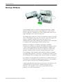
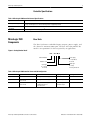
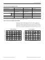
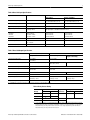
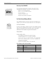
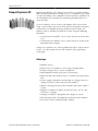
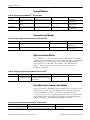
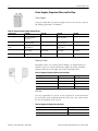
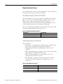
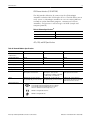
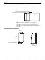
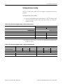
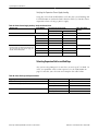
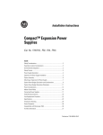
Technical Data
MicroLogix 1500 Programmable
Controllers
Bulletin 1764
2
MicroLogix 1500 Programmable Controllers
Table of Contents
MicroLogix 1500 System . . . . . . . . . . . . . . . . . . . . . . . . . . . . . . . . . . . . . . . . . . . . . . . . . . . .3
MicroLogix 1500 Components . . . . . . . . . . . . . . . . . . . . . . . . . . . . . . . . . . . . . . . . . . . . . . . .5
MicroLogix 1500 System Expansion . . . . . . . . . . . . . . . . . . . . . . . . . . . . . . . . . . . . . . . . . .10
Compact Expansion I/O . . . . . . . . . . . . . . . . . . . . . . . . . . . . . . . . . . . . . . . . . . . . . . . . . . . .11
Communications . . . . . . . . . . . . . . . . . . . . . . . . . . . . . . . . . . . . . . . . . . . . . . . . . . . . . . . . .15
Programming Instructions . . . . . . . . . . . . . . . . . . . . . . . . . . . . . . . . . . . . . . . . . . . . . . . . . .18
Programming Software . . . . . . . . . . . . . . . . . . . . . . . . . . . . . . . . . . . . . . . . . . . . . . . . . . . .18
Network and Programming Cables . . . . . . . . . . . . . . . . . . . . . . . . . . . . . . . . . . . . . . . . . . .19
Dimensions . . . . . . . . . . . . . . . . . . . . . . . . . . . . . . . . . . . . . . . . . . . . . . . . . . . . . . . . . . . . .20
System Expansion Calculations. . . . . . . . . . . . . . . . . . . . . . . . . . . . . . . . . . . . . . . . . . . . . .22
For More Information . . . . . . . . . . . . . . . . . . . . . . . . . . . . . . . . . . . . . . . . . . . . . . . . . . . . . .26
Tables and Figures
Table 1 - MicroLogix 1500 Controller General Specifications. . . . . . . . . . . . . . . . . . . . . . . .5
Figure 2 - Catalog Number Detail . . . . . . . . . . . . . . . . . . . . . . . . . . . . . . . . . . . . . . . . . . . . .5
Table 3 - MicroLogix 1500 Controller Power and I/O Configuration . . . . . . . . . . . . . . . . . . .5
Table 4 - Base Unit Power Supply Specifications . . . . . . . . . . . . . . . . . . . . . . . . . . . . . . . . .6
Figure 5 - Choosing a Power Supply for the 1764-28BXB . . . . . . . . . . . . . . . . . . . . . . . . . . .6
Table 6 - Base Unit Input Specifications . . . . . . . . . . . . . . . . . . . . . . . . . . . . . . . . . . . . . . . .7
Table 7 - Base Unit Output Specifications. . . . . . . . . . . . . . . . . . . . . . . . . . . . . . . . . . . . . . .7
Table 8 - Relay Contact Rating. . . . . . . . . . . . . . . . . . . . . . . . . . . . . . . . . . . . . . . . . . . . . . . .7
Table 9 - Environmental Specifications . . . . . . . . . . . . . . . . . . . . . . . . . . . . . . . . . . . . . . . . .8
Table 10 - Memory and Real-Time Clock Modules . . . . . . . . . . . . . . . . . . . . . . . . . . . . . . . .9
Table 11 - Compact Digital Input Modules Selection Chart . . . . . . . . . . . . . . . . . . . . . . . .12
Table 12 - Compact Digital Output Modules Selection Chart . . . . . . . . . . . . . . . . . . . . . . .12
Table 13 - Compact Combination Input and Output Module Selection Chart . . . . . . . . . . .12
Table 14 - Compact Analog I/O Modules Selection Chart. . . . . . . . . . . . . . . . . . . . . . . . . .13
Table 15 - Compact Temperature Input Modules Selection Chart . . . . . . . . . . . . . . . . . . .13
Table 16 - Compact High-Speed Counter Module Selection Chart . . . . . . . . . . . . . . . . . . .13
Table 17 - Compact DeviceNet Scanner Module Selection Chart. . . . . . . . . . . . . . . . . . . .13
Table 18 - Compact Power Supplies Specifications . . . . . . . . . . . . . . . . . . . . . . . . . . . . . .14
Table 19 - Compact Expansion Cables Selection Chart. . . . . . . . . . . . . . . . . . . . . . . . . . . .14
Table 20 - Compact End Caps Selection Chart . . . . . . . . . . . . . . . . . . . . . . . . . . . . . . . . . .14
Table 21 - MicroLogix 1500 Network Options . . . . . . . . . . . . . . . . . . . . . . . . . . . . . . . . . . .15
Table 22 - DH-485 Network Specifications . . . . . . . . . . . . . . . . . . . . . . . . . . . . . . . . . . . . .16
Table 23 - DeviceNet Specifications . . . . . . . . . . . . . . . . . . . . . . . . . . . . . . . . . . . . . . . . . .16
Table 24 - Ethernet Specifications. . . . . . . . . . . . . . . . . . . . . . . . . . . . . . . . . . . . . . . . . . . .17
Table 25 - Network Modules Specifications . . . . . . . . . . . . . . . . . . . . . . . . . . . . . . . . . . . .17
Table 26 - RSLogix 500 Selection Chart. . . . . . . . . . . . . . . . . . . . . . . . . . . . . . . . . . . . . . . .18
Table 27 - Controller and PC Port Identification . . . . . . . . . . . . . . . . . . . . . . . . . . . . . . . . .19
Figure 28 - Network Interface Devices Communication Port Identification . . . . . . . . . . . .19
Table 29 - Network Cable Selection Chart . . . . . . . . . . . . . . . . . . . . . . . . . . . . . . . . . . . . .19
Table 30 - Programming Cable Selection Chart. . . . . . . . . . . . . . . . . . . . . . . . . . . . . . . . . .19
Figure 31 - Compact I/O with MicroLogix 1500 Base Unit and Processor . . . . . . . . . . . . .20
Figure 32 - Expansion Bank with Power Supply, Expansion Cable, and End Cap . . . . . . . .20
Figure 33 - Spacing for Single-Wide and One and One-Half-Wide Modules . . . . . . . . . . .21
Figure 34 - Network Interface Devices Dimensions . . . . . . . . . . . . . . . . . . . . . . . . . . . . . .21
Table 35 - Selecting Hardware: Base Unit and Communications/Display Devices . . . . . .22
Table 36 - Selecting Hardware: Expansion I/O . . . . . . . . . . . . . . . . . . . . . . . . . . . . . . . . . .23
Table 37 - Base Unit Power Supply Loading - Verify the Current Limits . . . . . . . . . . . . . . .24
Table 38 - Base Unit Power Supply Loading - Verify the Required Power . . . . . . . . . . . . .24
Table 39 - Bank 1 Power Supply Loading - Verify the Current Limits . . . . . . . . . . . . . . . . .25
Table 40 - Select End Cap and Expansion Cable . . . . . . . . . . . . . . . . . . . . . . . . . . . . . . . . .25
Table 41 - Related Publications for MicroLogix 1500 Controllers . . . . . . . . . . . . . . . . . . . .26
Table 42 - MicroLogix 1000 and 1200 Technical Data Publications . . . . . . . . . . . . . . . . . .26
Publication 1764-TD001A-EN-P - March 2002
MicroLogix 1500 System
3
MicroLogix 1500 System
The MicroLogix 1500 is a world-class programmable logic control
platform with advanced features and performance. Many of these
features allow this controller to be used in applications where much
larger controllers were required in the past.
MicroLogix 1500 architecture features an innovative two-piece design
with a small footprint. The processor and base units slide together to
form the complete controller. The processor and base are
independently replaceable, allowing you to maximize your embedded
I/O options while minimizing inventory stocking costs.
Bulletin 1769 Compact I/O modules expand the controller’s
embedded I/O offerings and provide the additional flexibility to cover
a wide range of applications. This high-performance modular and
rackless I/O platform provides front accessibility for removal and
insertion, lowering system cost and reducing maintenance time.
The MicroLogix 1500 controller utilizes Rockwell Software RSLogix
500 programming software and shares a common instruction set with
the MicroLogix 1000, MicroLogix 1200 and SLC families of controllers.
New features are provided with an enhanced user interface that uses
function files to consolidate programming parameters. This simplifies
the user interface and increases controller performance.
A field-upgradable flash operating system ensures you will always be
up-to-date with the latest features, without having to replace
hardware. The controller can be easily updated with the latest
firmware via a web site download.
MicroLogix 1500 Programmable Controllers Technical Data
Publication 1764-TD001A-EN-P - March 2002
4
MicroLogix 1500 System
Advantages
• Large memory to solve a variety of applications. Memory size:
– 1764-LSP: 7K user program capacity
– 1764-LRP:14K user program capacity
• Field-upgradable flash operating system
• High performance expansion I/O options (up to 16 modules
depending on power budget and Base Unit)
• Advanced communications options including peer-to-peer and
SCADA/RTU networks, DH-485, DeviceNet, and Ethernet
– via the Communications Port on the Base Unit
– via the additional RS-232 port on the 1764-LRP processor
• Communications toggle push button
• Data file download protection prevents critical user data from
being altered via communications
• Battery (built-in and optional replacement)
• Mode switch for Run/Remote/Program
• Two built-in analog trim potentiometers
• Optional real-time clock
• Optional memory module
• Optional data access tool (DAT)
• 20 kHz high-speed counter, featuring 8 modes of operation
• Two high-speed outputs that can be configured as 20 kHz PTO
(Pulse Train Output) or as PWM (Pulse Width Modulated)
outputs
• Eight high-speed latching (pulse-catch) inputs
• 32-bit signed integer math
• Floating point data file
• Built-in PID capabilities
• ASCII read/write capability
• Recipe (RCP) instruction saves custom lists of recipe data
• Data logging (1764-LRP only) instruction stores data records
with optional time stamp
• Four event interrupt inputs (EII)
• 1 ms high-resolution timers
• 1 ms selectable timed interrupt (STI)
• Finger-safe terminal blocks meet global safety standards
• Removable terminal blocks allow pre-wiring
• Regulatory agency certifications for world-wide market (CE,
C-Tick, UL, c-UL, including Class I Division 2 Hazardous
Location)
Publication 1764-TD001A-EN-P - March 2002
MicroLogix 1500 Programmable Controllers Technical Data
MicroLogix 1500 Components
5
Controller Specifications
Table 1 MicroLogix 1500 Controller General Specifications
Specification
All 1764 Controllers
Memory Size and Type
if using 1764-LSP processor: 7K user memory (total user program plus data)
if using 1764-LRP processor: 14K user memory (total user program plus data)
Data Elements
configurable, user-defined file structure, 4K max. data size
Throughput
1 ms (for a typical 1K word user program)(1)
(1) A typical user program contains bit, timer, counter, math and file instructions.
MicroLogix 1500
Components
Base Units
The Base Unit houses embedded inputs, outputs, power supply, and
the channel 0 communications port. The base unit also provides the
interface to expansion I/O when required by an application.
Figure 2 Catalog Number Detail
1764 - 24 A W A
Bulletin Number
Power Supply
A = 120/240V ac
B = 24V dc
Number of I/O
Output Type:
W = Relay
X = Relay/24V dc FET
Input Type:
A = 120V ac
B = 24V dc
Table 3 MicroLogix 1500 Controller Power and I/O Configuration
Line Power
Inputs
Outputs
High Speed I/O
Catalog Number
120/240V ac
(12) 120V ac
(12) Relay, 2 isolated relays per unit
n/a
1764-24AWA
120/240V ac
(8) Standard 24V dc
(4) Fast 24V dc
(12) Relay, 2 isolated relays per unit
(4) 20 kHz input
1764-24BWA
24V dc
(8) Standard 24V dc
(8) Fast 24V dc
(6) Relay, 2 isolated relays per unit
(4) Standard 24V dc FET
(2) Fast 24V dc FET
(8) 20 kHz input
(2) 20 kHz output
1764-28BXB
MicroLogix 1500 Programmable Controllers Technical Data
Publication 1764-TD001A-EN-P - March 2002
6
MicroLogix 1500 Components
Table 4 Base Unit Power Supply Specifications
Specification
1764-24AWA
1764-24BWA
1764-28BXB
Power Supply Voltage
85 to 265V ac at 47 to 63 Hz
85 to 265V ac at 47 to 63 Hz
20.4 to 30V dc
Power Consumption
70 VA
88 VA
30W
Power Supply Max Inrush Current (max.)
120V ac: 25A for 8 ms
240V ac: 40A for 4 ms
120V ac: 25A for 8 ms
240V ac: 40A for 4 ms
24V dc: 4A for 150 ms
5V dc
2250 mA
2250 mA(2)
2250 mA
24V dc
400 mA
400 mA(2)
400 mA
Maximum Load Power
16W
22W
16W
24V dc Sensor Power
n/a
400 mA(2), 400 µF capacitance max.
n/a
Maximum Load Current(1)
(1) See System Expansion Calculations on page 22 for an example system validation worksheet to calculate expansion I/O power usage.
(2) Do not allow the total load power consumed by the 5V dc, 24V dc, and sensor power outputs to exceed 22W.
Figure 5 Choosing a Power Supply for the 1764-28BXB
This figure contains information for selecting a power supply for
applications using a 1764-28BXB base unit. Use the worksheets on
page22tocalculatethetotalpower(Watts)consumedbythesystem.Withthat
information, use the graphs below to choose a power supply. You can use
either current or power, depending on how the power supply is rated.
Input Power Required
1.4
30
1.2
Input Power Required (Watts)
Input Current Required at 24V dc (Amperes)
Input Current Required
1
0.8
0.6
0.4
0.2
0
25
20
15
10
5
0
0
2
4
6
8
10
12
Calculated Load Power (Watts)
Publication 1764-TD001A-EN-P - March 2002
14
16
18
0
2
4
6
8
10
12
14
16
18
Calculated Load Power (Watts)
MicroLogix 1500 Programmable Controllers Technical Data
MicroLogix 1500 Components
7
Table 6 Base Unit Input Specifications
Specification
1764-24AWA
1764-24BWA and 1764-28BXB
Inputs 0 thru 7
Inputs 8 and Higher
On-State Voltage Range
79 to 132V ac at 47 Hz to 63 Hz
14 to 30.0 V dc at 30°C (86°F)
14 to 26.4 V dc at 55°C (131°F)
10 to 30.0 V dc at 30°C (86°F)
10 to 26.4 V dc at 55°C (131°F)
Off-State Voltage Range
0 to 20V ac
0 to 5V dc
0 to 5V dc
Operating Frequency
n/a
1 kHz to 20 KHz
1 Hz to 500 Hz
Signal Delay
ON Delay = 20 ms
OFF Delay = 20 ms
standard inputs: selectable from 0.5 to 16 ms
high-speed inputs: selectable from 0.025 to 16 ms
On-State Current
Minimum
Nominal
Maximum
5.0 mA at 79V ac
12.0 mA at 120V ac
16.0 mA at 132V ac
2.5 mA at 14V dc
7.3 mA at 24V dc
12.0 mA at 30V dc
Off-State Leakage Current
2.5 mA minimum
1.5 mA minimum
1.5 mA minimum
Nominal Impedence
12K Ω at 50 hZ
10K Ω at 60 Hz
3.3K Ω
2.7K Ω
Inrush Current (max)
250 mA at 120V ac
n/a
n/a
2.0 mA at 10V dc
8.9 mA at 24V dc
12.0 mA at 30V dc
Table 7 Base Unit Output Specifications
Specification
1764-24AWA, -24BWA, -28BXB
1764-28BXB
Relay
FET Standard Operation
Operating Voltage Range
5 to 125V dc
5 to 264V ac
20.4 to 26.4V dc
Continuous Current per Point (max.)
See Table 8, Relay Contact Rating.
1A at 55°C (+131°F)
1.5A at 30°C (+86°F)
Continuous Current per Common (max.)
8.0A
6.0A
Continuous Current per Controller (max.)
24A at 150V
20A at 240V
18A at 150V
18A at 240V
On-State Current (min.)
5.0 mA at 79V ac
2.5 mA at 14V dc
Off-State Leakage Current (max.)
0 mA
1 mA
Signal Delay (max.) - resistive load
ON Delay = 10 ms
OFF Delay = 10 ms
ON Delay = 0.1 ms
OFF Delay = 1.0 ms
Surge Current per Point (peak)
n/a
4A for 10 ms(1)
FET High-Speed Operation
(Outputs 2 and 3 only)
100 mA
2.0 mA at 10V dc
ON Delay = 6 µs
OFF Delay = 18 µs
(1) Repeatability is once every 2 seconds at +55°C (+131°F), once every 1 second at +30°C (+86°F).
Table 8 Relay Contact Rating
Maximum
Voltage
Amperes
Make
Break
240V ac
7.5A
0.75A
120V ac
15A
1.5A
125V dc
24V dc
Amperes
Continuous
Voltamperes
Make
Break
2.5A
1800 VA
180 VA
0.22A(1)
1.0A
28 VA
1.2A(1)
2.0A
(1) For dc voltage applications, the make/break ampere rating for relay contacts can be determined by dividing 28
VA by the applied dc voltage. For example, 28 VA/48V dc = 0.58A. For dc voltage applications less than 48V, the
make/break ratings for relay contacts cannot exceed 2A. For dc voltage applications greater than 48V, the
make/break ratings for relay contact cannot exceed 1A.
MicroLogix 1500 Programmable Controllers Technical Data
Publication 1764-TD001A-EN-P - March 2002
8
MicroLogix 1500 Components
Table 9 Environmental Specifications
Description
1764 Controllers
Operating Temperature
+0°C to +55°C (+32°F to +131°F)
Storage Temperature
-40°C to +85°C (-40°F to +185°F)(1)
Operating Humidity
5% to 95% relative humidity (non-condensing)
Vibration
Operating: 10 to 500 Hz, 5G, 0.030 in. max. peak-to-peak
Relay Operation: 2G
Shock (without Data Access Tool installed)
Operating: 30G panel mounted (15G DIN Rail mounted)
Relay operation: 7.5G panel mounted (5G DIN Rail mounted)
Non-Operating: 40G panel mounted (30G DIN Rail mounted)
Shock (with Data Access Tool installed)
Operating: 20G panel mounted (15G DIN Rail mounted)
Relay operation: 7.5G panel mounted (5G DIN Rail mounted)
Non-Operating: 30G panel mounted (20G DIN Rail mounted)
Agency Certification
UL Listed Industrial Control Equipment
UL Listed Industrial Control Equipment for use in Canada
UL Listed Industrial Control Equipment for use in Class I,
Division 2 Hazardous Locations Groups A, B, C, D
Marked for all applicable directives
Marked for all applicable acts
N223
Electrical/EMC
The controller has passed testing at the following levels:
• EN 61000-4-2: 4 kV contact, 8 kV air, 4 kV indirect
• EN 61000-4-3: 10V/m, 80 to 1000 MHz, 80% amplitude modulation, +900 MHz keyed carrier
• EN 61000-4-4: 2 kV, 5 kHz; communications cable: 1 kV, 5 kHz
• EN 61000-4-5: communications cable 1 kV galvanic gun
I/O: 2 kV CM (common mode), 1 kV DM (differential mode)
AC Power Supply: 4 kV CM (common mode), 2 kV DM (differential mode)
DC Power Supply: 500V CM (common mode), 500V DM (differential mode)
• EN 61000-4-6: 10V, communications cable 3V
(1) Recommended storage temperature for maximum battery life (5 years typical with normal operating/storage conditions) of the 1764-RTC, 1764-MM1RTC, and
1764-MM2RTC is -40°C to +40°C (-40°F to +104°F). Battery life is significantly shorter at elevated temperatures.
Processors
In the controller system, the processor unit provides logic processing,
trim potentiometers, Run/Remote/Program mode switch,
communications toggle push button and (using the 1764-LRP
processor) an electrically isolated RS-232 port. The processor also
provides the interface to the DAT, real-time clock, and memory
modules.
There are two processor units: 1764-LSP and 1764-LRP.
Publication 1764-TD001A-EN-P - March 2002
MicroLogix 1500 Programmable Controllers Technical Data
MicroLogix 1500 Components
9
Data Access Tool (1764-DAT)
The DAT plug-in tool provides an interface for on-the-fly data
monitoring and adjustments. The DAT has five primary features:
• Direct access to 48 bit elements
• Direct access to 48 integer elements
• Two function keys
• Display of controller faults
• Removal and insertion under power
Real-Time Clock and Memory Modules
These optional modules attach to the processor unit. Both types of
modules can be inserted or removed while the unit is under power.
Real-Time Clock Modules
Real-time clock modules establish a time-base for controller functions
that need to be coordinated with real-time events. They provide year,
month, day of month, day of week, hour, minute, and second
information to the controller using the RTC function file.
Memory Modules
Memory modules allow:
• user programs and data to be stored as backup
• transport programs for use with other controllers
• safety/security for press control and other critical applications
• auto recovery, through a power cycle, after a controller fault
• comparison of programs
• Data file and memory module write protection
Table 10 Memory and Real-Time Clock Modules
Catalog Number
Function
Memory
1764-RTC
Real-Time Clock
not applicable
1764-MM1
Memory Module
8K
1764-MM1RTC
Memory Module and Real-Time Clock
8K
1764-MM2(1)
Memory Module
16K
1764-MM2RTC(1)
Memory Module and Real-Time Clock
16K
(1) For the 1764-LRP processor to support larger program and data requirements.
MicroLogix 1500 Programmable Controllers Technical Data
Publication 1764-TD001A-EN-P - March 2002
10
MicroLogix 1500 System
Expansion
MicroLogix 1500 System Expansion
To increase your I/O options, you can connect an additional bank of
I/O to your MicroLogix 1500 controller.
In a MicroLogix 1500 system, a maximum of one 1769 Expansion
cable can be used, allowing for two banks of I/O modules (one
connected directly to the controller and the other connected via the
cable). Each I/O bank(1) requires its own power supply (Bank 0 uses the
controller’s embedded power supply).
Only one power supply (embedded or expansion) may be used on an
I/O bank. The expansion power supply cannot be connected directly
to a controller. It must be connected using one of the expansion
cables.
Vertical Orientation
Horizontal Orientation
Expansion I/O
Bank 0
1769-CRRx(1)
Expansion Cable
1769-ECL
End Cap
Expansion I/O
Bank 1
Expansion
I/O Bank 0
1769-CRRx(1)
Expansion Cable
Expansion
I/O Bank 1
(1) The x in this catalog number can be either a 1 or a 3 representing the length of the cable:
1 = 1 foot (305 mm) and 3 = 3.28 feet (1 meter).
The following section of this document, Compact Expansion I/O, provides
information for choosing Compact I/O expansion options.
Basically, you select the I/O options you need and then verify that the
selections do not exceed the available power in the system. As shown
above, the power can be provided from the Base Unit or an
expansion power supply.
After reviewing the I/O options, use the worksheets in the “System
Expansion Calculations” section on page 22 to list your I/O choices and
determinethesystempowerrequirements.Theworksheetswillletyouknowif
the system is within allowable limits.
A download is also available for system validation. On the Internet, go
to http://www.ab.com/micrologix and navigate to MicroLogix 1500.
(1) An I/O bank is a group of I/O modules connected directly to one another. Banks are separated by cables.
Publication 1764-TD001A-EN-P - March 2002
MicroLogix 1500 Programmable Controllers Technical Data
Compact Expansion I/O
Compact Expansion I/O
11
High-density Bulletin 1769 Compact I/O rackless expansion modules
offer superior functionality and high value at a competitive price. With
a variety of modules, they complement and extend the capabilities of
the MicroLogix 1500 controller by maximizing flexibility of the I/O
count and type.
Up to 16 modules can be used in a MicroLogix 1500 system when
using a Series B Base Unit (up to 8 for Series A) dependent on power
requirements. In addition to staying within the power limits, the
modules must be distributed within the system using the following
limitations:
• a maximum of 8 modules can be connected directly to the Base
Unit
• a maximum of 8 modules can be connected to each side of the
Expansion Power Supply
Compact I/O provides an excellent platform for future enhancements,
so you can easily choose the level of control as your application
needs grow.
Advantages
•
•
•
•
•
•
•
•
•
•
•
MicroLogix 1500 Programmable Controllers Technical Data
Modular system
Feature-rich I/O to address a wide range of applications
Rackless design reduces system components
Small footprint shrinks panel space requirements
Front insertion and removal reduces assembly and replacement
time
Unique tongue-and-groove interlocking case design ensures a
strong, mechanical connection between modules
Software keying prevents incorrect module placement within a
system
Digital I/O modules available with AC/DC relay, 24V dc, and
120/240V ac voltages
Analog I/O modules configurable for voltage or current
Thermocouple, RTD, and High-Speed Counter input modules
DeviceNet scanner communications module
Publication 1764-TD001A-EN-P - March 2002
12
Compact Expansion I/O
Digital I/O Modules
Table 11 Compact Digital Input Modules(1) Selection Chart
Catalog Number
Description
Voltage Category
Number of Inputs
Commons per Module
Bus Current Draw (max.)
1769-IA16
AC
100/120V ac
16
1
115 mA at 5V dc
1769-IA8I
AC
100/120V ac
8
8
90 mA at 5V dc
1769-IM12
AC
200/240V ac
12
1
100 mA at 5V dc
1769-IQ16
DC (sink/source)
24V dc
16
2
115 mA at 5V dc
(1) Power Supply Distance Rating = 8. The maximum distance an I/O module may be located from the power supply is 8 modules.
Table 12 Compact Digital Output Modules(1) Selection Chart
Catalog
Number
Description
Voltage
Category
Number of
Outputs
Commons per Continuous Current
Module
per Point (max.)
Bus Current Draw (max.)
1769-OA8
AC
120/240V ac
8
2
0.25A at 60°C (140°F)
0.5A at 30°C (86°F)
145 mA at 5V dc
1769-OA16(2)
AC
120/240V ac
16
2
0.25A at 60°C (140°F)
0.5A at 30°C (86°F)
225 mA at 5V dc
1769-OB16
DC (source)
24V dc
16
1
0.5A at 60°C (140°F)
1.0A at 30°C (86°F)
200 mA at 5V dc
1769-OB16P
DC (source) with
Electronic Protection
24V dc
16
1
0.5A at 60°C (140°F)
1.0A at 30°C (86°F)
160 mA at 5V dc
1769-OV16
DC (sink)
24V dc
16
1
0.5A at 60°C (140°F)
1.0A at 30°C (86°F)
200 mA at 5V dc
1769-OW8
AC/DC Relay
5 to 265V ac
5 to 125V dc
8
2
1769-OW8I
AC/DC Relay
5 to 265V ac
5 to 125V dc
8
8
2.5A, Also see Table 8,
125 mA at 5V dc
Relay Contact Ratings on 100 mA at 24V dc
page 7.
125 mA at 5V dc
100 mA at 24V dc
1769-OW16(2)
AC/DC Relay
5 to 265V ac
5 to 125V dc
16
2
205 mA at 5V dc
180 mA at 24V dc
(1) Power Supply Distance Rating = 8. The maximum distance an I/O module may be located from the power supply is 8 modules.
(2) Dimensionally one and one-half as wide as other modules.
Table 13 Compact Combination Input and Output Module(1) Selection Chart
Catalog
Number
Description
Voltage
Category
Number of
Points
Commons per Continuous Current
Module
per Point (max.)
Bus Current Draw (max.)
1769-IQ6XOW4
DC (sink/source) inputs
24V dc
6 inputs
n/a
105 mA at 5V dc
AC/DC Relay outputs
5 to 265V ac
5 to 125V dc
4 outputs
2 (one for
inputs, one for
outputs)
2.5A
50 mA at 5V dc
(1) Power Supply Distance Rating = 8. The maximum distance an I/O module may be located from the power supply is 8 modules.
Publication 1764-TD001A-EN-P - March 2002
MicroLogix 1500 Programmable Controllers Technical Data
Compact Expansion I/O
13
Analog I/O Modules
Table 14 Compact Analog I/O Modules(1) Selection Chart
Catalog Number
Description
Input Channels per Module
Output Channels per Module
Bus Current Draw (max.)
1769-IF4
14-bit current/voltage input
module
4 differential or single-ended
n/a
120 mA at 5V dc
60 mA at 24V dc
1769-OF2
14-bit current/voltage output
module
n/a
2 single-ended
120 mA at 5V dc
120 mA at 24V dc
1769-IF4XOF2
8-bit combination input/output 4 differential or single-ended
module
2 single-ended
120 mA at 5V dc
160 mA at 24V dc
(1) Power Supply Distance Rating = 8. The maximum distance an I/O module may be located from the power supply is 8 modules.
Temperature Input Modules
Table 15 Compact Temperature Input Modules(1) Selection Chart
Catalog Number
Description
Input Channels per Module
Bus Current Draw (max.)
1769-IT6
supports thermocouple and millivolt signal measurement
6 input channels plus 2 CJC sensors
100 mA at 5V dc
40 mA at 24V dc
1769-IR6
supports RTD and direct resistance signal measurement
6 input channels
100 mA at 5V dc
45 mA at 24V dc
(1) Power Supply Distance Rating = 8. The maximum distance an I/O module may be located from the power supply is 8 modules.
High-Speed Counter Module
The 1769-HSC is a 1 MHz counter/encoder module with 4 on-board
outputs and 12 virtual outputs. Use this module for high-speed control
applications such as flow control, or measuring length, position,
speed, frequency or duration. The module can simultaneously
interface with up to 2 quadrature incremental encoders or 4
single-input counters.
Table 16 Compact High-Speed Counter Module Selection Chart(1)
Catalog Number Description
1769-HSC
Input Channels per Module
Output Channels per Module
1 MHz High-Speed
(4) single-input counters, or
(4) 5 to 30V dc sourcing outputs
Counter/Encoder Module (2) quadrature (ABZ) differential inputs
-30 to +30V dc
Bus Current Draw (max.)
425 mA at 5V dc
(1) Power Supply Distance Rating = 4. The maximum distance an I/O module may be located from the power supply is 4 modules.
DeviceNet Scanner Communications Module
Via the 1769-SDN, a MicroLogix 1500 controller can act as a DeviceNet
master, slave, or peer. The 1769-SDN provides standard DeviceNet
master functionality, as well as several new performance and
ease-of-use features. You can message between devices using one of
two methods (PCCC and Explicit messaging), and perform program
upload, download, and monitoring through the scanner.
Table 17 Compact DeviceNet Scanner Module(1) Selection Chart
Catalog Number
Description
Bus Current Draw (max.)
1769-SDN
DeviceNet Scanner Module
440 mA at 5V dc
(1) Power Supply Distance Rating = 4. The maximum distance an I/O module may be located from the power supply is 4 modules.
MicroLogix 1500 Programmable Controllers Technical Data
Publication 1764-TD001A-EN-P - March 2002
14
Compact Expansion I/O
Power Supplies, Expansion Cables, and End Caps
Power Supplies
Using an expansion I/O power supply increases the system’s capacity
for adding expansion I/O modules.
Table 18 Compact Power Supplies Specifications
Specification
1769-PA2
1769-PB2
1769-PA4
1769-PB4
Power Supply Voltage
85 to 265V ac (no jumper or
DIP switch required)
47 to 63 Hz
19.2 to 31.2V dc
85 to 132V ac (170 to 265 or
switch selectable)
19.2 to 31.2V dc
Power Consumption (max.)
100 VA at 120V ac
130 VA at 240V ac
50 VA at 24V dc
200 VA at 120V ac
240 VA at 240V ac
100 VA at 24V dc
Power Supply Inrush Current 25A at 132V ac
(max.)
40A at 240V ac
30A at 31.2V dc
25A at 132V ac
40A at 240V ac
30A at 31.2V dc
Maximum Load Current
2A at 5V dc
0.8A at 24V dc
2A at 5V dc
0.8A at 24V dc
4A at 5V dc
2A at 24V dc
4A at 5V dc
2A at 24V dc
24V dc Sensor Power
250 mA (max.) at 55°C
(131°F)
n/a
n/a
n/a
Expansion Cables
Expansion cables are required when adding a second bank of I/O
modules. They are connected from the right side of the controller
bank to either the left or right side of the expansion bank.
Table 19 Compact Expansion Cables Selection Chart
Cable Type
Length
Catalog Number
right bank-to-right bank
305 mm (1 ft)
1769-CRR1
right bank-to-right bank
1m (3.28 ft)
1769-CRR3
right bank-to-left bank
305 mm (1 ft)
1769-CRL1
right bank-to-left bank
1m (3.28 ft)
1769-CRL3
End Caps
In every expansion I/O system, an end cap must be used to terminate
the end of the serial communication bus. The end cap is connected to
the last I/O module in the system.
Table 20 Compact End Caps Selection Chart
Publication 1764-TD001A-EN-P - March 2002
End Cap
Catalog Number
right end cap
1769-ECR
left end cap
1769-ECL
MicroLogix 1500 Programmable Controllers Technical Data
Communications
Communications
15
MicroLogix 1500 Communications Advantages
• Enhanced RS-232 port (includes 24V dc power for network
interface devices)
• 300; 600; 1200; 4800; 9600; 19,200 and 38,400 baud rates
• RTS/CTS hardware handshake signals
• Connection to DH-485, DeviceNet and Ethernet networks
through the 1761-NET-AIC, 1761-NET-DNI and 1761-NET-ENI
interface modules
• Connection to modems for remote communications
• ASCII messaging provides dial-out capability
The MicroLogix 1500 allows you to choose the network that best
meets your needs.
Table 21 MicroLogix 1500 Network Options
If your application requires:
Use this network:
• Connection to dial-up modems for remote program maintenance or data collection
• Connection to leased-line or radio modems for use in SCADA systems
• Remote Terminal Unit (RTU) functions
DF1 Full-Duplex
DF1 Half-Duplex Slave
•
•
•
•
Plant-wide and cell-level data sharing with program maintenance
Data sharing between 32 controllers
Program upload, download, and monitoring to all controllers
Compatibility with multiple Allen-Bradley HMI devices
DH-485 via the 1761-NET-AIC
•
•
•
•
Connection of low-level multi-vendor devices directly to plant floor controllers
Data sharing between 64 devices
Better diagnostics for improved data collection and fault detection
Less wiring and reduced start-up time than traditional, hard-wired systems
DeviceNet via the
1761-NET-DNI
•
•
•
•
Program upload/download
Peer-to-peer communication
E-mail communication
10 base T-port with embedded LEDS
EtherNet/IP via the
1761-NET-ENI
• Connection to modems for remote data collection in a SCADA system
• Remote Terminal Unit (RTU) functions
Modbus RTU Slave
The following section provides information about the network
interface devices:
• AIC+ Advanced Interface Converter (1761-NET-AIC)
• DNI DeviceNet Interface (1761-NET-DNI)
• ENI Ethernet Interface (1761-NET-ENI)
MicroLogix 1500 Programmable Controllers Technical Data
Publication 1764-TD001A-EN-P - March 2002
16
Communications
Network Interface Devices
The network interface devices can be mounted on a panel or DIN rail.
See Figure 28 on page 19 for device drawings.
AIC+ Advanced Interface Converter (1761-NET-AIC)
The AIC+ provides an interface to DH-485 networks from an RS-232
port. It can be used with all MicroLogix controllers, SLC 5/03 and
higher, and a number of PanelView terminals. All devices
communicating on the network must be using DH-485 protocol. Do
not use DH-485 protocol to communicate with modems.
The AIC+ also provides isolation between all ports for a more stable
network and protection for connected devices.
Table 22 DH-485 Network Specifications(1)
Specification
1761-NET-AIC
Maximum Number of Nodes
32 per multidrop network
Maximum Length
1219m (4000 ft) per multidrop network
(1) See Table 25, Network Modules Specifications, for more 1761-NET-AIC specifications.
DNI DeviceNet Interface (1761-NET-DNI)
DNI capabilities:
• Peer-to-peer messaging between Allen-Bradley controllers and
other devices using the DF1 Full-Duplex protocol
• Programming and on-line monitoring over the DeviceNet
network
• With a DNI connected to a modem, you can dial in to any other
DNI-controller combination on DeviceNet
• Other DeviceNet products can send explicit (Get or Set)
messages with the DNI at any time
• The controller can initiate an explicit message to a UCMM
(Unconnected Message Manager) compatible device on
DeviceNet
Table 23 DeviceNet Specifications(1)
Specification
1761-NET-DNI
Maximum Number of Nodes
64
Maximum Length
500m at 125K baud or 100m at 500K baud
DeviceNet Agency Certification
ODVA conformance 2.0-A12
(1) See Table 25, Network Modules Specifications, for more 1761-NET-DNI specifications.
Publication 1764-TD001A-EN-P - March 2002
MicroLogix 1500 Programmable Controllers Technical Data
Communications
17
ENI Ethernet Interface (1761-NET-ENI)
The ENI provides EtherNet/IP connectivity for all MicroLogix
controllers and other DF1 Full-Duplex devices. The ENI allows you to
easily connect a MicroLogix controller to a new or existing Ethernet
network to update/download programs, communicate between
controllers, and generate e-mail messages via SMTP (simple mail
transport protocol).
Table 24 Ethernet Specifications(1)
Specification
1761-NET-ENI
Communication Rate
10 MHz
Connector
10Base-T (RJ45)
(1) See Table 25, Network Modules Specifications, for more 1761-NET-ENI specifications.
AIC+, DNI, and ENI Specifications
Table 25 Network Modules Specifications
Specification
1761-NET-AIC
1761-NET-DNI
1761-NET-ENI
24V dc Power Source
Requirements(1)
20.4 to 28.8V dc
11 to 25V dc
20.4 to 26.4V dc
24V dc Current Draw
120 mA
200 mA
100 mA
Inrush Current (max.)
200 mA
400 mA
200 mA
Internal Isolation
500V dc for 1 minute
500V dc for one minute
710V dc for one minute
Operating Temperature
0°C to +60°C (+32°F to +140°F)
Storage Temperature
-40°C to +85°C (-40°F to +185°F)
Humidity
5% to 95% non-condensing
Vibration
operating: 10 to 500 Hz, 5.0g, 0.030 in.
peak-to-peak, 2 hour each axis
operating: 5 to 2000 Hz, 2.5g, 0.015 in. operating: 10 to 500 Hz, 5.0g, 0.030 in.
peak-to-peak, 1 hour each axis
peak-to-peak, 2 hour each axis
non-operating: 5 to 2000 Hz, 5.0g, 0.030
in. peak-to-peak, 1 hour each axis
Shock
operating: 30g, ±3 times each axis
non-operating: 50g, ±3 times each axis
operating: 30g, ±3 times each axis
non-operating: 50g, ±3 times each axis
Agency Certification
(0°C to +55°C (+32°F to +131°F)
operating: 30g, ±3 times each axis
non-operating: 35g (DIN rail mount) 50g
(panel mount) ±3 times each axis
UL Listed Industrial Control Equipment
UL Listed Industrial Control Equipment for use in Canada
UL Listed Industrial Control Equipment for use in Class I,
Division 2 Hazardous Locations Groups A, B, C, D
Marked for all applicable directives
Marked for all applicable acts
N223
(1) When the device is connected to a MicroLogix controller, power is provided by the MicroLogix controller’s communication port.
MicroLogix 1500 Programmable Controllers Technical Data
Publication 1764-TD001A-EN-P - March 2002
18
Programming Instructions
Programming Instructions
The MicroLogix 1500 has the range of functionality necessary to
address diverse applications. The controller uses the following types
of instructions:
• Basic Instructions
• Comparison Instructions
• Data Instructions
• Communication Instruction, including ASCII
• Math Instructions
• Program Flow Control Instructions
• Application Specific Instructions
• High-Speed Counter Instruction
• High-Speed PTO (Pulse Train Output) and PWM (Pulse Width
Modulated) Instructions
• Recipe Instruction
• Data Logging Instruction (1764-LRP only)
Programming Software
The RSLogix 500 ladder logic programming package helps you
maximize performance, save project development time, and improve
productivity. This product has been developed to operate on
Windows® operating systems. RSLogix 500 can be used for
programming both the SLC 500 and MicroLogix controller families.
Table 26 RSLogix 500 Selection Chart
Publication 1764-TD001A-EN-P - March 2002
Catalog Number
Description
9324-RL0300ENE
RSLogix 500 Standard Edition Programming Software for SLC 500 and
MicroLogix controller families. (CD-ROM)
9324-RL0100ENE
RSLogix 500 Starter Edition Programming Software for MicroLogix
controller families. (CD-ROM)
9324-RL0700NXENE
RSLogix 500 Professional Edition. CD-ROM also includes RSLogix Emulate
500, RSNetworx for DeviceNet and RSNetworx for ControlNet.
MicroLogix 1500 Programmable Controllers Technical Data
Network and Programming Cables
19
Network and Programming
Cables
Use the communication cables listed below with MicroLogix 1500
controllers. Cables come in several lengths and connector styles to
provide connectivity between MicroLogix controllers and other
devices.
MicroLogix 1500 controllers require Series C versions of all 1761
cables.
Table 27 Controller and PC Port Identification
Device
Port
MicroLogix 1500 Base Unit Communications Port
8-pin Mini DIN
MicroLogix 1500 LRP Processor Communications Port
9-Pin D Shell
Personal Computer Communications Port
9-Pin D Shell
Figure 28 Network Interface Devices Communication Port Identification
AIC+
DNI
DeviceNet
ENI
ETHERNET
V±
RS232
CAN_L
FAULT
NET
SHIELD
CAN_H
DH-485
V+
RS-232
8-PIn Mini DIN
NET
MOD
TX/RX
Ethernet
NODE
TX/RX
IP
DANGER
RS-232
8-PIn Mini DIN
PWR
NOTE: The AIC+ is recommended
for isolation purposes when the
controller and an operator
interface device are not using the
same power supply.
TX/RX
CABLE
GND
RS-232
9-PIn D Shell
EXTERNAL
RS-232
8-PIn Mini DIN
Table 29 Network Cable Selection Chart
Connectors
Length
Catalog Number
Connectors
Length
Catalog Number
8-pin Mini DIN to 8-pin Mini DIN
0.5m (1.5 ft)
1761-CBL-AM00
8-pin Mini DIN to 9-pin D Shell
0.5m (1.5 ft)
1761-CBL-AP00
8-pin Mini DIN to 8-pin Mini DIN
2m (6.5 ft)
1761-CBL-HM02
8-pin Mini DIN to 9-pin D Shell
2m (6.5 ft)
1761-CBL-PM02
8-pin Mini DIN to 8-pin Mini DIN
5m (16 ft)
2711-CBL-HM05
8-pin Mini DIN to 9-pin D Shell
5m (16 ft)
2711-CBL-PM05
8-pin Mini DIN to 8-pin Mini DIN
10m (32 ft)
2711-CBL-HM10
8-pin Mini DIN to 9-pin D Shell
10m (32 ft)
2711-CBL-PM10
9-pin D Shell to 9-pin D Shell
0.5m (1.5 ft)
1761-CBL-AC00
6-pin Phoenix to RJ45 (DH-485)
3m (10 ft)
1761-CBL-AS03
9-pin D Shell to 9-pin D Shell
3m (10 ft)
1747-CP3
6-pin Phoenix to RJ45 (DH-485)
9m (30 ft)
1761-CBL-AS09
Table 30 Programming Cable Selection Chart
MicroLogix 1000, 1200, and 1500
Channel 0 (8-pin Mini DIN)
MicroLogix 1500 with 1764-LRP Processor
Channel 1 (9-pin RS-232)
Catalog Number
Length
Catalog Number
Length
1761-CBL-PM02
2m (6.5 ft)
1747-CP3
3m (10 ft)
1761-CBL-HM02
2m (6.5 ft)
n/a
MicroLogix 1500 Programmable Controllers Technical Data
Programming Device
Personal Computer (9-pin D Shell)
Hand-Held Programmer (HHP)
Publication 1764-TD001A-EN-P - March 2002
20
Dimensions
Dimensions
NOTE: All dimensions are in mm (inches). Hole spacing tolerance: ±0.04 mm (0.016 in.).
Figure 31 Compact I/O with MicroLogix 1500 Base Unit and Processor
28.5 mm
(1.12 in)
147.4 mm (5.81 in)
35 mm
(1.38 in)
118 mm (4.65 in)
59 mm
(2.32 in)
147 mm
(5.79 in)
59 mm
(2.32 in)
122.6 mm (4.83 in)
DIN Rail
Center Line
35 mm
(1.38 in)
13.5 mm
(0.53 in)
controller depth = 87 mm (3.43 in)
controller spacing = 50 mm (2 in) on all sides for adequate ventilation
132 mm (5.19 in)
168 mm
(6.62 in)
Mounting Hole
Dimension
14.7 mm
(0.58 in)
Figure 32 Expansion Bank with Power Supply, Expansion Cable, and End Cap
controller depth = 87 mm (3.43 in)
controller spacing = 50 mm (2 in) on all sides for adequate ventilation
Expansion Cable connector and End Cap have identical dimensions.
Publication 1764-TD001A-EN-P - March 2002
35 mm
(1.38 in)
35 mm 35 mm
(1.38 in) (1.38 in)
28.5 mm
(1.12 in)
132 mm (5.19 in)
35 mm
(1.38 in)
118 mm (4.65 in)
59 mm
(2.32 in)
59 mm
(2.32 in)
122.6 mm (4.83 in)
DIN Rail
Center Line
35 mm
(1.38 in)
70 mm
(2.76 in)
147.4 mm (5.81 in)
35 mm
(1.38 in)
Mounting Hole
Dimension
14.7 mm
(0.58 in)
MicroLogix 1500 Programmable Controllers Technical Data
Dimensions
21
Figure 33 Spacing for Single-Wide and One and One-Half-Wide Modules
Panel Mounting Using the Dimensional Template:
Spacing for single-wide modules 35 mm (1.378 in.)
Spacing for one-and-a half-wide modules 52.5 mm (2.067 in.)
Host Controller
Spacing from controller to first I/O mounting hole 35 mm (1.378 in.)
Note: Overall hole spacing tolerance: ±0.4 mm (0.016 in.).
Locate holes every 17.5 mm (0.689 in.) to allow for a mix of
single-wide (e.g. 1769-IQ16) and one-and-one-half-wide modules (e.g.
1769-OA16).
Figure 34 Network Interface Devices Dimensions
52.07 mm
(2.05 in.)
107 mm
(4.20 in.)
118 mm
(4.64 in.)
Allow 15 mm (0.6 in) for DIN rail latch
movement during installation and removal.
27.7 mm
(1.09 in.)
MicroLogix 1500 Programmable Controllers Technical Data
6.6 mm
(0.26 in.)
AIC+ only
64.8 mm
(2.55 in.)
71.4 mm
(2.81 in.) AIC+ only
Publication 1764-TD001A-EN-P - March 2002
22
System Expansion Calculations
System Expansion
Calculations
A download is also available for system validation. On the Internet, go
to http://www.ab.com/micrologix and navigate to MicroLogix 1500.
The procedure in this publication consists of:
• Selecting System Devices
• Verifying the System Loading
• Selecting Expansion Cables and End Caps
Selecting System Devices
1. Use Table 35 to select the processor and optional communications or
display devices. Enter a 1 in the “Select Devices” column.
2. Enter the current draw values in the “Calculated Current for
System” columns. If an external power supply will be used to
power communication devices, do not include their current
draw values in this calculation. Add up the current draw values
to determine the “SUBTOTAL1” values.
Table 35 Selecting Hardware: Base Unit and Communications/Display Devices
Catalog Number
Select
Device(s)
Choose a Processor, LSP or LRP:
1764-LSP
1764-LRP
Bus Current Draw Specification
at 5V dc (mA)
at 24V dc (mA)
300
380
350
1764-DAT(1) optional
Communications/Display Devices, optional, one only maximum:
0
1761-NET-AIC(1)
1761-NET-ENI(1)
2707-MVH232 or
2707-MVP232(1)
Calculated Current for System
at 5V dc (mA)
at 24V dc (mA)
0
0
0
120(2)
0
100(2)
0
80(2)
SUBTOTAL1
(1)
(A1)
(B1)
These are optional accessories. Current is consumed only if the accessory is installed.
(2) Current for the AIC+ and ENI may be supplied by controller communications port or from an external 24V dc source. No current is consumed from the controller when a
user-supplied, external source is used. If an external source is to be used, do not select the device here. The current for a 2707-MVH232 or 2707-MVP232 MicroView
Operator Interface is supplied from the controller communication port, when directly connected.
3. Use Table 36 to select the I/O modules. Enter the number of modules
in either the “Base Unit Expansion” or the “Bank 1” column.
IMPORTANT
Publication 1764-TD001A-EN-P - March 2002
When planning the system layout, keep in
mind that each module has a “Power Supply
Distance Rating”. This is the maximum distance
an I/O module may be located from the power
supply. For most modules, the rating is 8. For
the 1769-HSC and 1769-SDN, the rating is 4.
MicroLogix 1500 Programmable Controllers Technical Data
System Expansion Calculations
23
Depending on its configuration, the 1769-SDN may transfer large
amounts of data into and out of the controller I/O image tables.
Care should be taken when using more than three of these
modules to verify that they are optimally configured. This will
ensure that the maximum available 4K data table size will not be
exceeded. Refer to the 1769-SDN User Manual for more details.
4. Enter the current draw values in the “Calculated Current”
columns. Add up the current draw values to determine the
“SUBTOTAL2” values.
5. Verify that the total number of modules does not exceed the
system limits.
Table 36 Selecting Hardware: Expansion I/O
Select I/O Modules for Each Bank:
Expansion I/O
Base Unit
Modules
Expansion
n1
Catalog Number
1769-IA16
1769-IA8I
1769-IF4 (Series A)
1769-IF4 (Series B)
1769-IF4XOF2
1769-IM12
1769-IQ16
1769-IQ6XOW4
1769-IR6
1769-IT6
1769-OA8
1769-OA16
1769-OB16
1769-OB16P
1769-OF2 (Series A)
1769-OF2 (Series B)
1769-OV16
1769-OW8
1769-OW8I
1769-OW16
1769-HSC
1769-SDN
TOTAL MODULES:
Bank 1
n2
Number of Modules(1)
Bus Current Draw
Specification (mA)
X
at 5V dc
Y
at 24V dc
115
90
120
120
120
100
115
105
100
100
145
225
200
160
120
120
200
125
125
205
425
440
0
0
150
60
160
0
0
50
45
40
0
0
0
0
200
120
0
100
100
180
0
0
SUBTOTAL2:
Calculate Current Draw:
Calculated Current for
Base Unit Expansion (mA)
n1 x X
n1 x Y
at 5V dc
at 24V dc
(A2)
(B2)
Calculated Current for
Bank 1 Power Supply (mA)
n2 x X
n2 x Y
at 5V dc
at 24V dc
(C)
(D)
(1) Up to 16 modules may be used in a MicroLogix 1500 system when using a Series B Base Unit and Series C processor (up to 8 for Series A Base Units).
A maximum of 8 modules can be connected directly to the Base Unit.
A maximum of 8 modules can be connected to each side of the Expansion Power Supply.
MicroLogix 1500 Programmable Controllers Technical Data
Publication 1764-TD001A-EN-P - March 2002
24
System Expansion Calculations
Verifying the System Loading
To have a valid system, both current and power requirements must be
satisfied.
Verifying the Base Unit Loading
1. Enter the SUBTOTAL values from Tables 35 and 36. Add the total
current draw for the Base Unit. Verify the values are within the
maximum limits.
Table 37 Base Unit Power Supply Loading - Verify the Current Limits
Current from:
Calculated Current for System
at 5V dc (mA)
at 24V dc (mA)
For 1764-24BWA only, enter sum of any User 24V dc Sensor Current
(E)
MAXIMUM LIMIT
400 mA User 24V dc
Values from SUBTOTAL1
(A1)
(B1)
Values from SUBTOTAL2
(A2)
(B2)
TOTAL BASE UNIT CURRENT LOADING
(F)
(G)
MAXIMUM LIMIT
2250 mA at 5V dc
400 mA at 24V dc
2. Using the table below, verify that the MAXIMUM POWER LIMIT
is not exceeded.
Table 38 Base Unit Power Supply Loading - Verify the Required Power
Catalog Number:
1764-24AWA, 1764-28BXB
1764-24BWA
5V Power Calculation
(F)
x 5V
=W
(F)
x 5V
=W
24V Power Calculation
(G)
x 24V
=W
(G)
x 24V
=W
(E)
x 24V
=W
Add up Total Watts
MAXIMUM POWER LIMIT
Publication 1764-TD001A-EN-P - March 2002
W
W
16W
22W
MicroLogix 1500 Programmable Controllers Technical Data
System Expansion Calculations
25
Verifying the Expansion Power Supply Loading
Using the values from SUBTOTAL2, verify that the system loading and
I/O distribution are within the limits shown in Table 39. Consider future
expansion when selecting a power supply.
Table 39 Bank 1 Power Supply Loading - Verify the Current Limits
Specification
Catalog Number
Calculated Current for System
at 5V dc (mA)
Values from SUBTOTAL2 (on page 23):
MAXIMUM CURRENT LIMIT
I/O Distribution - Distribute I/O modules such
that the current consumed from either the left
side or the right side of the power supply never
exceeds the following values:
24V dc User Output
Capacity
at 24V dc (mA)
(C)
(D)
1769-PA2
2000
800
250 mA
1769-PA4
4000
2000
n/a
1769-PB2
2000
800
1769-PB4
4000
2000
1769-PA2
2000
800
1769-PA4
2000
1000
1769-PB2
2000
800
1769-PB4
2000
1000
250
Selecting Expansion Cables and End Caps
Any system using Compact I/O must have an end cap. If I/O Bank 1 is
used, an expansion cable is also required. Use the information on
page 14 to make your selection and complete the table below.
Table 40 Select End Cap and Expansion Cable
Type of System
Requirement
Catalog Number Selected
Base Unit with Compact I/O only
right end cap
1769-ECR
Base Unit with Compact I/O and Bank 1, horizontal orientation
right-to-left expansion cable
right end cap
Base Unit with Compact I/O and Bank 1, vertical orientation
right-to-right expansion cable
left end cap
MicroLogix 1500 Programmable Controllers Technical Data
1769-ECR
1769-ECL
Publication 1764-TD001A-EN-P - March 2002
26
For More Information
For More Information
Available Documentation
MicroLogix 1500 user documentation presents information according
to the tasks you perform and the programming environment you use.
Refer to the table below for information on MicroLogix 1500
publications.
Table 41 Related Publications for MicroLogix 1500 Controllers
Title
Publication Number
MicroLogix 1500 Programmable Controllers User Manual
1764-UM001
MicroLogix 1200 and MicroLogix 1500 Instruction Set Reference Manual 1762-RM001
Compact I/O System Overview
1769-SO001
1769 Compact I/O Power Supplies and Communication Bus Expansion
Cables Technical Data
1769-TD001
Compact Analog I/O and Temperature Input Modules Technical Data
1769-TD004
Compact I/O Analog Modules User Manual
1769-UM002
Compact I/O 1769-IT6 Thermocouple/mV Input Module User Manual
1769-UM004
Compact I/O 1769-IR6 RTD/Resistance Input Module User Manual
1769-UM005
Compact 1769-HSC High Speed Counter Module User Manual
1769-UM006
Compact 1769-SDN DeviceNet Scanner Module User Manual
1769-UM009
AIC+ Advanced Interface Converter User Manual
1761-6.4
DeviceNet Interface User Manual
1761-6.5
Ethernet Interface User Manual
1761-UM006
Allen-Bradley Programmable Controller Grounding and Wiring Guidelines 1770-4.1
If you would like a technical data for the MicroLogix 1000 or
MicroLogix 1200 controllers, refer to the following table.
Table 42 MicroLogix 1000 and 1200 Technical Data Publications
Publication 1764-TD001A-EN-P - March 2002
See this Document
Publication Number
MicroLogix 1000 Technical Data
1761-TD001
MicroLogix 1200 Technical Data
1762-TD001
MicroLogix 1500 Programmable Controllers Technical Data
For More Information
27
MicroLogix Downloads
Visit the MicroLogix web site at http://www.ab.com/micrologix to
learn more about MicroLogix products and download MicroLogix
software utilities and manuals. Software utilities are available for
configuring the DNI and ENI network interface devices. System
validation worksheets are available to determine I/O power usage.
Manuals are available in PDF format. To purchase a printed manual or
download a free electronic version, visit us at
http://www.theautomationbookstore.com. For fast access to related
publications, visit the MicroLogix Internet site
http://www.ab.com/micrologix. Electronic versions of our manuals
are available for you to search and download.
Rockwell Software Web Site
For more information on Rockwell Software products, such as RSLogix
500, please visit their web site at http://www.rockwellsoftware.com.
MicroLogix 1500 Programmable Controllers Technical Data
Publication 1764-TD001A-EN-P - March 2002
Allen-Bradley, SLC, MicroLogix, Compact, RSLogix, RSNetworx, ControlNet, MicroView, and PanelView are trademarks of Rockwell Automation.
DeviceNet is a trademark of Open DeviceNet Vendors Association (ODVA).
Publication 1764-TD001A-EN-P - March 2002 28
Supersedes Publication 1764-SO001B-EN-P - May 2000
Copyright © 2002 Rockwell Automation. All rights reserved. Printed in the U.S.A.