1
Allen-Bradley
Bulletin 2707
MicroView
Operator
Interface
Module
(Cat. No. 2707–MVH232)
User
Manual
Important User
Information
Because of the variety of uses for the products described in this
publication, those responsible for the application and use of this
control equipment must satisfy themselves that all necessary steps
have been taken to assure that each application and use meets all
performance and safety requirements, including any applicable laws,
regulations, codes and standards.
The illustrations, charts, sample programs and layout examples
shown in this guide are intended solely for purposes of example.
Since there are many variables and requirements associated with any
particular installation, Allen-Bradley does not assume responsibility
or liability (to include intellectual property liability) for actual use
based upon the examples shown in this publication.
Allen-Bradley publication SGI-1.1, Safety Guidelines for the
Application, Installation, and Maintenance of Solid-State Control
(available from your local Allen-Bradley office), describes some
important differences between solid-state equipment and
electromechanical devices that should be taken into consideration
when applying products such as those described in this publication.
Reproduction of the contents of this copyrighted publication, in
whole or in part, without written permission of Allen-Bradley
Company, Inc., is prohibited.
Throughout this manual we use notes to make you aware of safety
considerations:
!
ATTENTION: Identifies information about practices
or circumstances that can lead to personal injury or
death, property damage or economic loss.
Attention statements help you to:
• identify a hazard
• avoid the hazard
• recognize the consequences
Important:
Identifies information that is critical for successful
application and understanding of the product.
ControlNet is a trademark; PLC is a registered trademark of Allen-Bradley Company, Inc.
Table of Contents
MicroView Operator Interface Module
User Manual
Using this Manual
Chapter 1
Objectives . . . . . . . . . . . . . . . . . . . . . . . . . . . . . . . . . . . . . . . . . . . . . . . . .
Contents . . . . . . . . . . . . . . . . . . . . . . . . . . . . . . . . . . . . . . . . . . . . . . . . . .
Intended Audience . . . . . . . . . . . . . . . . . . . . . . . . . . . . . . . . . . . . . . . . . . .
Conventions . . . . . . . . . . . . . . . . . . . . . . . . . . . . . . . . . . . . . . . . . . . . . . .
Related Publications . . . . . . . . . . . . . . . . . . . . . . . . . . . . . . . . . . . . . . . . .
MicroView Overview
Chapter 2
Objectives . . . . . . . . . . . . . . . . . . . . . . . . . . . . . . . . . . . . . . . . . . . . . . . . .
General Information . . . . . . . . . . . . . . . . . . . . . . . . . . . . . . . . . . . . . . . . . .
Description . . . . . . . . . . . . . . . . . . . . . . . . . . . . . . . . . . . . . . . . . . . . . . . .
Display . . . . . . . . . . . . . . . . . . . . . . . . . . . . . . . . . . . . . . . . . . . . . . .
Keypad . . . . . . . . . . . . . . . . . . . . . . . . . . . . . . . . . . . . . . . . . . . . . . .
Communications Port . . . . . . . . . . . . . . . . . . . . . . . . . . . . . . . . . . . . .
Power Connector . . . . . . . . . . . . . . . . . . . . . . . . . . . . . . . . . . . . . . . .
Keypad . . . . . . . . . . . . . . . . . . . . . . . . . . . . . . . . . . . . . . . . . . . . . . . . . . .
Function Key Operations . . . . . . . . . . . . . . . . . . . . . . . . . . . . . . . . . . . .
MODE Key Operations . . . . . . . . . . . . . . . . . . . . . . . . . . . . . . . . . . . . . .
Communications Port . . . . . . . . . . . . . . . . . . . . . . . . . . . . . . . . . . . . . . . . .
RS-232 Communications . . . . . . . . . . . . . . . . . . . . . . . . . . . . . . . . . . . . . .
Programming the MicroView . . . . . . . . . . . . . . . . . . . . . . . . . . . . . . . . . . . .
MicroView Programming Software (MDPS) . . . . . . . . . . . . . . . . . . . . . . .
Upload/Download Connections . . . . . . . . . . . . . . . . . . . . . . . . . . . . . . . .
Default Settings . . . . . . . . . . . . . . . . . . . . . . . . . . . . . . . . . . . . . . . . . . . . .
Operating Parameters . . . . . . . . . . . . . . . . . . . . . . . . . . . . . . . . . . . . . .
Operating System . . . . . . . . . . . . . . . . . . . . . . . . . . . . . . . . . . . . . . . . .
Product Options . . . . . . . . . . . . . . . . . . . . . . . . . . . . . . . . . . . . . . . . . . . . .
Product Accessories . . . . . . . . . . . . . . . . . . . . . . . . . . . . . . . . . . . . . . . . .
Initial Setup and
Mode Menu
1–1
1–1
1–2
1–2
1–2
2–1
2–1
2–2
2–2
2–2
2–3
2–3
2–3
2–4
2–5
2–5
2–6
2–6
2–6
2–7
2–7
2–7
2–8
2–8
2–8
Chapter 3
Objectives . . . . . . . . . . . . . . . . . . . . . . . . . . . . . . . . . . . . . . . . . . . . . . . . .
Apply Power . . . . . . . . . . . . . . . . . . . . . . . . . . . . . . . . . . . . . . . . . . . . . . .
Powerup Sequence . . . . . . . . . . . . . . . . . . . . . . . . . . . . . . . . . . . . . . . . . .
Powerup Sequence . . . . . . . . . . . . . . . . . . . . . . . . . . . . . . . . . . . . . . . .
Mode Menu . . . . . . . . . . . . . . . . . . . . . . . . . . . . . . . . . . . . . . . . . . . . . . . .
Resetting the MicroView . . . . . . . . . . . . . . . . . . . . . . . . . . . . . . . . . . . . . . .
To reset the MicroView: . . . . . . . . . . . . . . . . . . . . . . . . . . . . . . . . . . . . .
Setting Communication Parameters Manually . . . . . . . . . . . . . . . . . . . . . . .
Special Functions for Controller Operations . . . . . . . . . . . . . . . . . . . . . . . . .
P-A/D . . . . . . . . . . . . . . . . . . . . . . . . . . . . . . . . . . . . . . . . . . . . . . . . . .
Mode . . . . . . . . . . . . . . . . . . . . . . . . . . . . . . . . . . . . . . . . . . . . . . . . . .
Prgrm . . . . . . . . . . . . . . . . . . . . . . . . . . . . . . . . . . . . . . . . . . . . . . . . . .
Clr Flt . . . . . . . . . . . . . . . . . . . . . . . . . . . . . . . . . . . . . . . . . . . . . . . . . .
3–1
3–1
3–2
3–2
3–4
3–5
3–5
3–5
3–6
3–6
3–6
3–6
3–6
i
Table of Contents
MicroView Operator Interface Module
User Manual
Master Security Code . . . . . . . . . . . . . . . . . . . . . . . . . . . . . . . . . . . . . . . .
To Enter a New Master Security Code: . . . . . . . . . . . . . . . . . . . . . . . . . .
Enabling / Disabling Scaling . . . . . . . . . . . . . . . . . . . . . . . . . . . . . . . . . . . .
To Enable or Disable Scaling: . . . . . . . . . . . . . . . . . . . . . . . . . . . . . . . . .
Using the Simulate Mode . . . . . . . . . . . . . . . . . . . . . . . . . . . . . . . . . . . . . .
To Simulate an Application: . . . . . . . . . . . . . . . . . . . . . . . . . . . . . . . . . . .
Test Functions . . . . . . . . . . . . . . . . . . . . . . . . . . . . . . . . . . . . . . . . . . . . . .
Transferring Applications
Chapter 4
Objectives . . . . . . . . . . . . . . . . . . . . . . . . . . . . . . . . . . . . . . . . . . . . . . . . .
Upload / Download Connections . . . . . . . . . . . . . . . . . . . . . . . . . . . . . . . . .
Computer Setup . . . . . . . . . . . . . . . . . . . . . . . . . . . . . . . . . . . . . . . . . . . .
Downloading an Application . . . . . . . . . . . . . . . . . . . . . . . . . . . . . . . . . . . .
Uploading an Application . . . . . . . . . . . . . . . . . . . . . . . . . . . . . . . . . . . . . .
Running Applications
5–1
5–1
5–1
5–2
5–2
5–2
5–2
5–3
5–3
5–3
5–4
5–4
5–4
5–4
5–5
5–5
5–6
Chapter 6
Objectives . . . . . . . . . . . . . . . . . . . . . . . . . . . . . . . . . . . . . . . . . . . . . . . . .
Safety Guidelines . . . . . . . . . . . . . . . . . . . . . . . . . . . . . . . . . . . . . . . . . . .
Operating Environment . . . . . . . . . . . . . . . . . . . . . . . . . . . . . . . . . . . . . . .
Enclosures . . . . . . . . . . . . . . . . . . . . . . . . . . . . . . . . . . . . . . . . . . . . . . . .
Connecting DC Power . . . . . . . . . . . . . . . . . . . . . . . . . . . . . . . . . . . . . . . .
ii
4–1
4–1
4–2
4–2
4–7
Chapter 5
Chapter Objectives . . . . . . . . . . . . . . . . . . . . . . . . . . . . . . . . . . . . . . . . . .
Application Documentation . . . . . . . . . . . . . . . . . . . . . . . . . . . . . . . . . . . . .
Bit Write Mode . . . . . . . . . . . . . . . . . . . . . . . . . . . . . . . . . . . . . . . . . . . . . .
Screen Types . . . . . . . . . . . . . . . . . . . . . . . . . . . . . . . . . . . . . . . . . . . . . .
Screen Navigation . . . . . . . . . . . . . . . . . . . . . . . . . . . . . . . . . . . . . . . . . . .
Screen Links . . . . . . . . . . . . . . . . . . . . . . . . . . . . . . . . . . . . . . . . . . . . .
Advisor Option . . . . . . . . . . . . . . . . . . . . . . . . . . . . . . . . . . . . . . . . . . . .
Function Keys . . . . . . . . . . . . . . . . . . . . . . . . . . . . . . . . . . . . . . . . . . . .
Auto Return . . . . . . . . . . . . . . . . . . . . . . . . . . . . . . . . . . . . . . . . . . . .
Continue . . . . . . . . . . . . . . . . . . . . . . . . . . . . . . . . . . . . . . . . . . . . . .
Menu and Sub-Menu Screens . . . . . . . . . . . . . . . . . . . . . . . . . . . . . . . . . . .
Main Menu . . . . . . . . . . . . . . . . . . . . . . . . . . . . . . . . . . . . . . . . . . . . . .
Sub-Menus . . . . . . . . . . . . . . . . . . . . . . . . . . . . . . . . . . . . . . . . . . . . . .
Security Screens . . . . . . . . . . . . . . . . . . . . . . . . . . . . . . . . . . . . . . . . . . . .
Data Display Screens . . . . . . . . . . . . . . . . . . . . . . . . . . . . . . . . . . . . . . . .
Data Entry Screens . . . . . . . . . . . . . . . . . . . . . . . . . . . . . . . . . . . . . . . . . .
Recipe Screens . . . . . . . . . . . . . . . . . . . . . . . . . . . . . . . . . . . . . . . . . . . . .
Installation
3–7
3–7
3–8
3–9
3–9
3–9
3–11
6–1
6–1
6–1
6–1
6–2
Table of Contents
MicroView Operator Interface Module
User Manual
Communication
Connections and Setup
Chapter 7
Troubleshooting and
Maintenance
Chapter 8
Chapter Objectives . . . . . . . . . . . . . . . . . . . . . . . . . . . . . . . . . . . . . . . . . .
Wiring Guidelines . . . . . . . . . . . . . . . . . . . . . . . . . . . . . . . . . . . . . . . . . . .
Connecting RS-232 Devices . . . . . . . . . . . . . . . . . . . . . . . . . . . . . . . . . . . .
To connect the MicroView to the MicroLogix controller: . . . . . . . . . . . . .
Communicating with a Logic Controller . . . . . . . . . . . . . . . . . . . . . . . . . . . .
Communications Parameters . . . . . . . . . . . . . . . . . . . . . . . . . . . . . . . . .
Chapter Objectives . . . . . . . . . . . . . . . . . . . . . . . . . . . . . . . . . . . . . . . . . .
Troubleshooting Recommendations . . . . . . . . . . . . . . . . . . . . . . . . . . . . . .
Equipment Required . . . . . . . . . . . . . . . . . . . . . . . . . . . . . . . . . . . . . . . . .
Common Operating Problems . . . . . . . . . . . . . . . . . . . . . . . . . . . . . . . . . . .
Error Messages . . . . . . . . . . . . . . . . . . . . . . . . . . . . . . . . . . . . . . . . . . . . .
Communication Error Codes . . . . . . . . . . . . . . . . . . . . . . . . . . . . . . . . . . . .
Using the Test Functions . . . . . . . . . . . . . . . . . . . . . . . . . . . . . . . . . . . . . .
To access the test functions: . . . . . . . . . . . . . . . . . . . . . . . . . . . . . . . .
Display Test . . . . . . . . . . . . . . . . . . . . . . . . . . . . . . . . . . . . . . . . . . . . . . .
To perform the display test: . . . . . . . . . . . . . . . . . . . . . . . . . . . . . . . . .
Core ROM Test . . . . . . . . . . . . . . . . . . . . . . . . . . . . . . . . . . . . . . . . . . . . .
To perform the Core ROM test: . . . . . . . . . . . . . . . . . . . . . . . . . . . . . .
System RAM Test . . . . . . . . . . . . . . . . . . . . . . . . . . . . . . . . . . . . . . . . . . .
To perform the System RAM Test: . . . . . . . . . . . . . . . . . . . . . . . . . . . .
System ROM Test . . . . . . . . . . . . . . . . . . . . . . . . . . . . . . . . . . . . . . . . . . .
To perform the System ROM Test: . . . . . . . . . . . . . . . . . . . . . . . . . . . .
Program ROM Test . . . . . . . . . . . . . . . . . . . . . . . . . . . . . . . . . . . . . . . . . .
To perform the Program ROM Test: . . . . . . . . . . . . . . . . . . . . . . . . . . .
Keyboard Test . . . . . . . . . . . . . . . . . . . . . . . . . . . . . . . . . . . . . . . . . . . . . .
To perform the keyboard test: . . . . . . . . . . . . . . . . . . . . . . . . . . . . . . .
Communications Port Test . . . . . . . . . . . . . . . . . . . . . . . . . . . . . . . . . . . . .
To test the communications port: . . . . . . . . . . . . . . . . . . . . . . . . . . . . .
Watchdog Test . . . . . . . . . . . . . . . . . . . . . . . . . . . . . . . . . . . . . . . . . . . . .
To perform the Watchdog Test: . . . . . . . . . . . . . . . . . . . . . . . . . . . . . .
Cleaning the Display Window . . . . . . . . . . . . . . . . . . . . . . . . . . . . . . . . . . .
Removing Paint and Grease . . . . . . . . . . . . . . . . . . . . . . . . . . . . . . . .
7–1
7–1
7–2
7–2
7–3
7–3
8–1
8–1
8–1
8–2
8–2
8–3
8–4
8–4
8–5
8–5
8–5
8–5
8–6
8–6
8–7
8–7
8–8
8–8
8–8
8–8
8–10
8–10
8–11
8–11
8–12
8–12
iii
Table of Contents
MicroView Operator Interface Module
User Manual
Specifications
Appendix A
MicroView Specifications . . . . . . . . . . . . . . . . . . . . . . . . . . . . . . . . . . . . . .
MicroView Cable Diagrams
Appendix B
MicroView Cables . . . . . . . . . . . . . . . . . . . . . . . . . . . . . . . . . . . . . . . . . . .
Catalog No. 2707-NC9 . . . . . . . . . . . . . . . . . . . . . . . . . . . . . . . . . . . . . .
Catalog No. 1761-CBL-HM02, 2707-NC11 . . . . . . . . . . . . . . . . . . . . . . . .
MicroView Special
Controller Functions
iv
A–1
B–1
B–2
B–3
Appendix C
Objectives . . . . . . . . . . . . . . . . . . . . . . . . . . . . . . . . . . . . . . . . . . . . . . . . .
Accessing Special Functions . . . . . . . . . . . . . . . . . . . . . . . . . . . . . . . . . . .
Accessing Special Functions . . . . . . . . . . . . . . . . . . . . . . . . . . . . . . . . . . .
Using the P-A/D Function . . . . . . . . . . . . . . . . . . . . . . . . . . . . . . . . . . . . . .
MicroLogix File Types . . . . . . . . . . . . . . . . . . . . . . . . . . . . . . . . . . . .
Reading Controller Input and Output Files . . . . . . . . . . . . . . . . . . . . . . . . . .
Reading / Writing Controller Status Files . . . . . . . . . . . . . . . . . . . . . . . . . . .
Reading / Writing Controller Binary and Integer Files . . . . . . . . . . . . . . . . . .
Reading / Writing Controller Timer Files . . . . . . . . . . . . . . . . . . . . . . . . . . . .
Reading / Writing Controller Counter Files . . . . . . . . . . . . . . . . . . . . . . . . . .
Reading / Writing Controller Control Files . . . . . . . . . . . . . . . . . . . . . . . . . . .
Using the Mode Function . . . . . . . . . . . . . . . . . . . . . . . . . . . . . . . . . . . . . .
Using the Program Function . . . . . . . . . . . . . . . . . . . . . . . . . . . . . . . . . . . .
Using the Clear Fault Function . . . . . . . . . . . . . . . . . . . . . . . . . . . . . . . . . .
To clear controller faults: . . . . . . . . . . . . . . . . . . . . . . . . . . . . . . . . . . .
C–1
C–1
C–2
C–2
C–2
C–3
C–4
C–5
C–6
C–8
C–10
C–12
C–13
C–14
C–14
Chapter
A–B
1
Using this Manual
Objectives
Read this chapter to familiarize yourself with the rest of the manual.
You will learn about:
•
•
•
•
Contents
Contents of this manual
Intended audience
Conventions
Related publications
The following table lists the contents of each chapter:
Chapter
Title
1
Using this Manual
2
Overview of MicroView
3
Initial Setup and Main Menu
4
Transferring Application Files
5
Running Applications
Describes the basic screen types.
Also describes the different function
key operations.
6
Installation
Provides procedures for mounting the
MicroView. Also provided are wiring
instructions and recommendations.
7
Communication
Connections and Setup
Describes RS-232 connections. Setup
guidelines are provided for MicroLogix
controllers.
8
Troubleshooting
and Maintenance
Provides assistance in identifying
and correcting common operating
problems. Cleaning recommendations
are also provided.
Appendix A
Specifications
Appendix B
Cable Diagrams
Appendix C
MicroView Special Controller
Functions
Purpose
Provides an overview of the manual.
Contains a description of the MicroView
and accessory devices.
Describes initial desktop setup of the
MicroView using main menu functions.
Describes how to upload and download
application files between the MicroView
and a personal computer.
Index
1–1
Chapter 1
Using this Manual
Intended Audience
No special knowledge is required to operate the MicroView. If you are
wiring the MicroView, you must be familiar with the electrical codes in your
area (see inside front cover).
You should be familiar with the MicroView Programming Software (see
related publications below).
Conventions
This manual uses the following conventions:
• Keys that you press on the MicroView are enclosed in brackets [ ].
For example: [NEXT] refers to the NEXT key on the MicroView.
• References to menus are initial cap followed by the word Menu.
For example: Special Menu, Main Menu, Other Menu
• All MicroView displays are shown inside a rectangular box.
1 Reset
2 Comm
Related Publications
3 Spec
4 Other
The following publications may be helpful for additional reference.
MicroView Publications
Publication / Catalog
Number
2707-805 May 95 or Later
MicroView Programming Software, Programming Manual
2707-801 April 95 or Later
DTAM Programming Software, Programming Manual
Title
Other Publications
Publication / Catalog
Number
1761-6.1 August 1994 or
Later
1–2
Title
MicroLogix User Manual
Chapter
A–B
2
MicroView Overview
Objectives
This chapter describes the MicroView and accessories.
It contains these sections:
Section
General Information
Page
General Information
2–1
Description
2–2
Keypad
2–3
Communications Port
2–5
RS-232 Communications
2–6
Programming the MicroView
2–6
Default Settings
2–7
Accessories
2–8
The MicroView interfaces with the MicroLogix controller. The MicroView
allows operators to monitor and manipulate process data on the plant floor.
RS-232 Port. The MicroView has an RS-232 communications port. The
RS-232 port allows point-to-point connections with a MicroLogix controller.
The RS-232 port also allows the MicroView to be connected to an IBM TM
compatible personal computer.
Memory Capability. Storage of the operating system, configuration
information, and user-programmed screens are maintained in nonvolatile
memory providing storage for approximately 50 screens.
Recipe Operations. Recipe type functions allow operators to quickly modify
blocks of data. Download data to a maximum of 10 non-sequential register
addresses per screen. Link multiple recipe screens to download data to more
than 10 addresses.
Flexible Function Key Operations. Two function keys provide a convenient
way to trigger screen displays and change display screens.
Point-Access/Display Function. Allows you to monitor or modify data files
in MicroLogix controllers. Use this function to set up and debug application
programs.
2–1
Chapter 2
MicroView Overview
Description
The front panel of the MicroView terminal is shown below.
Figure 2.1
MicroView (front view)
Power Port
Communications Port
MicroView
Martha
Childs
UNLOCK THE POWER
TO VIEW
F1
F2
1
2
3
MENU
MODE
4
5
6
PREV
NEXT
7
8
9
CE
+/–
.
0
Display
The 2 line by 16 character display uses high contrast LCD technology with
LED backlighting.
Keypad
The keypad is separated by color into easily identified groups or functions. In
addition, each key has a raised dome in the center to provide tactile feedback.
2–2
Chapter 2
MicroView Overview
Figure 2.2
MicroView (Top view)
Power Port
Communications Port
Communications Port
The MicroView operator interface has a communications port located on the
top edge. The communications port is an 8 pin mini DIN connector
configured with an RS-232 channel and a 24 VDC power supply connection.
Power Connector
The power connector is a 2 conductor power jack used to connect an external
power source to the MicroView. This power source is required when the
MicroView is connected to a PC for program transfers.
Keypad
Figure 2.3
Keypad
F1
F2
1
2
3
MENU
MODE
4
5
6
PREV
NEXT
7
8
9
.
0
CE
+/–
The MicroView uses a sealed membrane, tactile feedback keypad. The keys
are color coded to easily identify key functions.
2–3
Chapter 2
MicroView Overview
Key Color
Function
Blue
Function Keys, F1 and F2
Dark Grey
Display/Format Control
Light Grey
Numeric Entry
The following table defines the function of each keypad key.
Key
Function
Returns to the main menu of an application.
MENU
Accesses special features and configuration of MicroView operating
parameters.
Steps back through a sequence of linked screens.
MODE
PREV
Steps forward through a sequence of linked screens.
NEXT
Clears an entire value during data entry.
CE
Toggles a data entry value between positive or negative.
+\–
Enters a decimal point.
0
9
F1
F2
Sends data to the controller. Data can either be default values or data
entered at the keyboard.
Enters numbers 0 to 9 during data entry or selects a numbered item
shown on the display.
Displays any application screen assigned to the key. These keys can also
set or clear bits at two consecutive registers in the controller data table.
Function Key Operations
F1
F2
Function keys can be linked to application screens allowing quick access to
critical data display or data entry screens. For example, if the F1 function
key is linked to Recipe Screen 10, the operator can press F1 at any point in
the application to download recipe registers on screen 10 to the processor.
A control mode can be assigned to each function key linked to a screen.
Control Mode
Auto Return
Continue
Bit Write Mode
2–4
Function
Returns to the screen displayed before the function key was pressed.
Continues to the next screen in the link regardless of the screen displayed
before the function key was pressed.
Allows the function key when pressed to set or clear a bit in the controller.
Bit Write Mode operates with either Auto Return or Continue mode.
The function keys access 2 contiguous word data elements defined by the
user. For example, assign function keys F1 to F2 to N7:20 and N7:21.
Chapter 2
MicroView Overview
MODE Key Operations
MODE
The MODE key accesses a menu of options allowing you to set features and
operating parameters of the MicroView.
1 Reset
2 Comm
1 Code
2 Scal
Baud Rate
Mode Menu
Select this option:
1 Reset
2 Comm
1 Baud Rate
1 P-A/D
3 Spec
4 Other
3 Sim
4 Test
5 Ex
1 P-A/D
2 Mode
3 Prgrm
4 Clr Flt
To perform this function:
Resets the Unit
Specifies 300, 1200, 2400, 9600, 19200 bits per second
Displays and/or modifies data files in the processor.
2 Mode
Places processor in RUN mode or PROGRAM mode.
3 Prgrm (Program)
Transfers application files between the MicroView and PC.
4 Clr Flt (Clear Fault)
Clears all processor faults in the MicroLogix controller.
1 Code
Modifies the master security code of the MicroView.
2 Scal (Scale)
Converts controller values to engineering units.
3 Sim (Simulate)
Verifies an application without controller connected.
4 Test
Tests memory, communications, keyboard and display.
5 Ex (Exit)
Returns to the Mode menu.
3 Special
4 Other
Communications Port
All communications are through an 8 pin mini DIN connector on the top of
the MicroView. The connector is an RS-232 port.
Figure 2.4
MicroView Communications Port
PIN #
8
7
6
5
3
4
2
1
8-Pin Female C DIN Connector
1
2
3
4
5
6
7
8
Mounting
Signal Name
+ 24 VDC from MicroLogix
VDC Common
Cable Shield
Receive Data (RXD)
Not Used
Not Used
Transmit Data (TXD)
Signal Ground
Cable Shield
2–5
Chapter 2
MicroView Overview
RS-232 Communications
The RS-232 port allows point-to-point communications with MicroLogix
controllers.
Figure 2.5
RS-232 Communications
MicroView to MicroLogix Controller
MicroLogix Controller
MicroLogix Communications Cable
Catalog No. 1761-CBL-HM02
Catalog No. 2707-NC9 or
Catalog No. 2707-NC11
RS-232
MicroView Operator Interface
Programming
the MicroView
The MicroView is programmed off-line using a personal computer running
MicroView Programming Software (MDPS). Operating system upgrades can
also be transferred using an IBMTM compatible personal computer.
MicroView Programming Software (MDPS)
You can use MicroView Programming Software (Catalog No. 2707-NP2,
Version 1.00 or later) or DPS software (Catalog No. 2707-NP, Version 5.00
or later) to create application screens for the MicroView Operator Terminal.
For a description of MicroView Programming Software (MDPS), refer to the
Programming Manual (Publication No. 2707-805).
2–6
Chapter 2
MicroView Overview
Upload/Download Connections
For programming and configuration, the MicroView is connected to your
computer’s RS-232 port. using a programming cable (Catalog No.
2707-NC8). See Appendix B if you need to construct your own cable .
Figure 2.6
Upload/Download Connections
Programming Computer
Com 1 or Com 2
RS-232
Programming Cable
Catalog No. 2707-NC8
Power Supply
(Upload/Download Only)
MicroView
Operator Interface
Default Settings
The MicroView is preset at the factory with the following defaults:
Operating Parameters
The default operating functions are shown in the table below. The operating
functions can be set using the MicroView Mode Menu. Refer to Chapter 3.
Function
Com-Port
Co
- or
Otherr
Parameter
Default Value
Baud
9600
Data Bits
8 (Fixed)
Parity
None (Fixed)
Simulate
Off
Master Code
00000000 (All zeros)
Scale
On
2–7
Chapter 2
MicroView Overview
Operating System
The MicroView is provided with a default application file using MicroLogix
DF1 operating system.:
The application file displays a screen with the message:
No Application
Program Loaded
Product Options
Product Accessories
2–8
The table below lists the options available for the MicroView.
Item
Catalog No.
Description
MicroView
2707-MVH232
Hand-Held MicroView with RS-232 Communications Port
MicroView
2707-MVP232
Panel-Mount MicroView with RS-232 Communications Port
Programming
Software
2707-NP
(Version 5.00
or later)
Use to create application screens for the MicroView on
a personal computer. Software allows completed applications to be transferred between the MicroView and a personal computer. Will also support application development
for DTAM Plus and DTAM Micro operator interfaces.
2707-NP2
Version 1.00
or later
Use to create application screens for the MicroView on
a personal computer. Software allows completed applications to be transferred between a personal computer and
the MicroView.
The following accessories are available for the MicroView.
Item
Catalog No.
Description
MicroView Face Plate
Mounting Kit
2707-MVMNT
Allows the 2707-MVH232 hand-held MicroView to be
surface-mounted to a panel. The MicroView unit slides
into panel adapter housing. An integral cable
assembly connects the MicroView 8 pin DIN connector
to an 8 pin DIN connector on the panel adapter.
MicroView
Programming Cable
2707-NC8
RS-232 cable connects MicroView and a personal
computer. Use to upload or download applications with
a personal computer running DPS or MDPS software.
MicroLogix
Communications Cable
1761-CBL-HM02
2707-NC11
RS-232 cable connects MicroView to MicroLogix
controller for run-time operations. (Length: 2 meters)
MicroLogix
Communications Cable
2707-NC9
RS-232 cable connects MicroView to MicroLogix
controller for run-time operations .(Length: 15 meters)
120V AC to DC Adapter
2707-PS120
Provides DC voltage output for the MicroView.
Operates on 120 VAC input line voltage.
220V AC to DC Adapter
2707-PS220
Provides DC voltage output for the MicroView.
Operates on 220 VAC input line voltage.
Chapter
A–B
3
Initial Setup and Mode Menu
Objectives
This chapter describes how to apply power to and then configure the
MicroView using the menu keys. Instructions on how to use the Simulate
mode to run an application are also provided. This chapter contains the
following sections:
Section
Apply Power
Page
Apply Power
3–1
Powerup Sequence
3–2
Mode Menu
3–4
Resetting the MicroView
3–5
Setting Communication Parameters Manually
3–5
Special Functions for Controller Operations
3–6
Entering a New Master Security Code
3–7
Enabling or Disabling Scaling
3–8
Using the Simulate Mode
3–9
Test Functions
3–11
This section describes power connections for initial desktop setup and
programming. Refer to Chapter 6 for installation wiring instructions.
The MicroView operates on 24 VDC power supplied either through the
power port or the communications port. For run-time operations with the
MicroLogix controller, the MicroView is supplied with 24 VDC through the
cable from the MicroLogix controller connected to the communications port.
For application download/upload operations, the MicroView is supplied with
24 VDC through the power port using a separate power adapter. You can use
the AC to DC Adapters: Catalog No. 2707-PS120 for 120 VAC or Catalog
No. 2707-PS220 for 220 VAC power.
!
ATTENTION: Verify that the power is disconnected from the
power source before wiring. Failure to disconnect power may
result in electrical shock.
If you use an AC/DC power adapter, make sure that the supply
voltage to the MicroView is 11 to 25 volts DC and of the correct
polarity. Incorrect voltage may damage the MicroView.
3–1
Chapter 3
Initial Setup and Mode Menu
1. Connect the AC to DC Adapter to the MicroView’s power port.
Point-to-Point Connectivity
MicroLogix Controller
Communications Cable
1761-CBL-HM02
2707-NC9 or
2707-NC11
MicroView
Operator Interface
Upload/Download
Programming Computer
Programming Cable
2707-NC8
MicroView
Operator Interface
Power Supply
2707-PS120 or 2707-PS220
(Upload/Download Only)
2. Apply power to the MicroView by plugging the AC to DC Adapter into
the proper power source (check adapter label to verify voltage).
The MicroView performs a powerup sequence.
Powerup Sequence
The powerup sequence is automatic, you do not have to respond to
the screens. During the Power Up or Reset sequence, the MicroView
performs a series of initialization and diagnostic tests.
Powerup Sequence
1. When power is first applied, the display will light and remain blank for
approximately one second.
2. Then the display is tested, every pixel of the display is turned on for one
second. If all of the pixels do not turn on, the display may be defective.
ÎÎÎ
Î
ÎÎ
ÎÎ
Î
Î
Î
Î
ÎÎ
Î
ÎÎ
ÎÎÎ
ÎÎÎÎ
ÎÎ
ÎÎÎÎÎ
ÎÎÎÎ
3–2
Chapter 3
Initial Setup and Mode Menu
3. The display is again cleared and the MicroView verifies the system
memory checksum, program checksum and system RAM.
4.. If all tests pass, the MicroView will flash the boot code power-up screen
for one second.
MicroView
Core: 1.01 (c) 1995
5. The following operating system screens are displayed. The first two flash
briefly. The third screen is displayed until the MicroView is connected to
the controller or the user presses a valid key.
MicroView
FRN: 1.01 (c) 1995
MicroView
MicroLogix DF1
MicroView DF1
Attempting Link
3–3
Chapter 3
Initial Setup and Mode Menu
Mode Menu
Access the Mode Menu by pressing the [MODE] key. All other functions are
halted when the menu is displayed.
The Mode Menu provides access to four functions:
1 Reset
2 Comm
3 Spec
4 Other
Select a menu item by pressing the corresponding numeric key [1] [4].
The menu structure is shown below:
1 Reset
2 Comm
3 Spec
4 Other
Resets the MicroView
Baud Rate
“NEXT”
To
1 P-A/D
2 Mode
9600
Change
Special
Controller Operations
Configures MicroView
Communications Port
1 Code
2 Scal
Sets Master
Security Code
3–4
Enables / Disables
Scaling
3 Prgrm
4 Clr Flt
3 Sim
4 Test
Performs
Functional Tests
5 Ex
Simulates Controller
Communications
Exits to
Mode Menu
Chapter 3
Initial Setup and Mode Menu
Resetting the MicroView
Use the reset function to reset the MicroView after configuration changes
using the Mode Menu.
To reset the MicroView:
1. From the Mode Menu select [1] Reset.
1 Reset
2 Comm
3 Spec
4 Other
You are prompted:
1 = Reset
0 = Abort
2. Press [1] on the keypad to initiate the reset.
The MicroView resets. This has the same effect as turning the power off
and on. The MicroView performs the self diagnostic tests and powerup
displays as described in the Powerup Sequence.
Setting Communication
Parameters Manually
The communication function on the Mode Menu lets you to manually set the
baud rate of the communication port. Normally this parameter is set
automatically from the programming software when an application is
downloaded.
Select [2] Comm from the Mode Menu.
1 Reset
2 Comm
3 Spec
4 Other
Baud Rate
“Next”
to
9600
Change
This menu displays:
Press [Prev] or [Next] to select a new rate: 300, 1200, 2400, 9600 or 19200.
Press [
] to save the new Baud rate setting. The screen will display:
COPYING TO MEM
Please Wait ....
After the new parameter is saved, the MicroView will again display the
Mode Menu screen.
1 Reset
2 Comm
3 Spec
4 Other
3–5
Chapter 3
Initial Setup and Mode Menu
Special Functions for
Controller Operations
The Special Menu item provides access to special features for the controller
operations.
Select [3] Spec from the Mode Menu.
1 Reset
2 Comm
3 Spec
4 Other
This menu displays:
1 P-A/D
2 Mode
3 Prgrm
4 Clr Flt
Note: Below are brief descriptions of each menu item.
Refer to Appendix C for instructions on using the Special Menu items.
P-A/D
Use the Point Access / Display function to display and modify controller data
files. The P-A/D function does not allow you to write to controller Input and
Output files. Appendix C provides a listing of the applicable file types for
MicroLogix controllers along with step-by-step instructions.
Mode
Select Mode to place the controller in either the run or program modes. This
may be useful if you need to halt the controller for memory transfers.
Prgrm
Use the Program transfer function to initiate a transfer of data between a
MicroView and a MicroLogix controller. The Program Mode uploads and
downloads application programs between the MicroView and a personal
computer.
Clr Flt
Use the Clear Fault function to clear all major and minor faults in the
controller.
3–6
Chapter 3
Initial Setup and Mode Menu
Master Security Code
The master security code provides access to all screen security codes and
allows them to be modified. The master security code is initially set by the
application program written using the MDPS or DPS software. See Catalog
No. 2707-805 or 2707-801 (April 1995 or later) for more information.
Two master security codes perform special functions:
00000000 allows the operator to modify the existing master code without
entering the current code.
99999999 does not allow operator to modify security codes. Changing of
the master security code is only permitted through DPS software.
To Enter a New Master Security Code:
1. From the Mode Menu, select [4] Other.
1 Reset
2 Comm
3 Spec
4 Other
The Other Menu appears:
1 Code
2 Scal
3 Sim
4 Test
5 Ex
2. Press [1] Code to select the Master security code function.
The master code entry screen displays:
Enter Master
Code:_
3. Enter the current code and press [
].
You are prompted to enter the new code.
Enter New Master
Code:_
4. Enter a new code and press [
]. The code must be 8 digits in length. If
you enter less than 8 digits the entry is padded with zeroes. For example,
an entry of 1234 is entered as12340000.
The screen will display:
COPYING TO MEM
Please Wait ....
After the new parameter is saved, the MicroView will again display:
1 Code
2 Scal
3 Sim
4 Test
5 Ex
3–7
Chapter 3
Initial Setup and Mode Menu
Note: Security codes can contain the wildcard character ? Any entered
value will be treated as a match to the wildcard. You must make sure that the
master security code is different from security codes using wildcard entries.
Otherwise the master security code may be seen as a security code. For
example, if the:
Security Code =12??????
Master Code = 12368794
When the master security code above is entered, the MicroView interprets it
as a security code.
Enabling / Disabling Scaling
Use scaling to convert data from a controller to engineering units such as
gallons or psi. When scaling is disabled, the values are not converted. Refer
to the MicroView Programming Software Manual for a description of how
values are scaled. The scaling factor is determined by the application
designer, it cannot be changed by the operator.
Flow Rate
Transducer
MicroView displays
scaled value of
16 Gallons Per Minute
MicroLogix Controller
Flow Rate
Transducer
Value = 510
3–8
Value From
Controller = 510
Chapter 3
Initial Setup and Mode Menu
To Enable or Disable Scaling:
1. From the Mode Menu, select item [4] Other.
1 Reset
2 Comm
3 Spec
4 Other
The Other Menu appears:
1 Master
2 Scal
3 Sim
4 Test
5 Ex
2. Select item [2] Scal.
The scale enable screen displays:
Scale
0=Off
OFF (0)
1=On
Current Setting
3. Press [1] on the keypad to enable scaling and [0] to disable scaling.
The screen will display:
COPYING TO MEM
Please Wait ....
After the new parameter is saved, the MicroView will again display:
1 Code
2 Scal
3 Sim
4 Test
5 Ex
4. Select item [5] Ex to exit to the Mode Menu.
Using the
Simulate Mode
The Simulate mode checks an application without having a controller
connected. All data that normally would be sent by the controller, such as
data for a display, is set to “0.” Any ASCII data is set to “?”. Selecting the
Simulate function from the Mode Menu will:
• Halt communication between the MicroView and the controller.
• Simulate communication with a controller.
Disabling the Simulate mode resumes normal operation.
To Simulate an Application:
1. Download the application from the DPS software.
2. From the Mode Menu, select item [4] Other.
1 Reset
2 Comm
3 Spec
4 Other
3–9
Chapter 3
Initial Setup and Mode Menu
The Other Menu appears:
1 Code
2 Scal
3 Sim
4 Test
5 Ex
3. Select item [3] Sim.
The simulate enable screen displays:
Simulate
0=Off
OFF (0)
1=On
Current Setting
4. Press [1] to enable the Simulate mode.
The screen will display:
COPYING TO MEM
Please Wait ....
After the new parameter is saved, the MicroView will again display:
1 Code
2 Scal
3 Sim
4 Test
5 Ex
5. Press [5] Ex to exit the Other Menu and display the Mode Menu.
1 Reset
2 Comm
3 Spec
4 Other
6. From the Mode Menu, reset the MicroView.
The MicroView displays a series of diagnostic tests, enters run mode,
loads the application and then displays the Mode Menu of the application.
7. Run the program as you normally would. Notice that all display registers
show data as a set of zeroes.
Pressure = 0000 PSI
Data Display
8. After verifying the operation of the program, press the [MODE] key.
All other functions are halted and the Mode Menu is displayed.
9. Disable the Simulate mode.
3–10
Chapter 3
Initial Setup and Mode Menu
Test Functions
Selecting Test from the Other Menu displays the test screen:
Diagnostic Tests
<Test Selection>
Current Test Selection
Use the Test menu to perform the following:
•
•
•
•
•
•
•
•
•
Display
Core ROM
System RAM
System ROM
Program ROM
Keyboard
Comm Port
Watchdog
Reset
Refer to Chapter 8, Troubleshooting and Maintenance for instructions on
how to perform these tests.
3–11
Chapter
A–B
4
Transferring Applications
Objectives
Upload / Download
Connections
This chapter describes how to transfer applications between the offline
programming software (DPS) operating on a personal computer and the
MicroView. It contains the following sections:
Section
Page
Upload/Download Connections
4–1
Computer Setup
4–2
Downloading an Application
4–2
Uploading an Application
4–7
To upload or download an application to the MicroView, you must:
• connect a power supply (refer to Chapter 3).
• connect the (Catalog No. 2707-NC8) programming cable.
Power Port
Communications Port
Power Supply
2707-PS120 or 2707-PS220
(Upload/Download Only)
MicroView Programming Cable
Catalog No. 2707-NC8
To Computer
RS-232 Port
4–1
Chapter 4
Transferring Application Files
Computer Setup
Upload and download functions are initiated from a personal computer
running the programming software DPS (Catalog No. 2707-NP, Version 5.00
or later) or the MicroView programming software MDPS (Catalog No.
2707-NP2, Version 1.00 or later). All data transfer functions automatically
occur at 9600 Baud.
After the transfer is complete, the baud rate is set to the parameters defined
by the application program residing in the MicroView.
Downloading
an Application
This section shows how to download an application from a computer running
DPS software (Catalog No. 2707-NP, Version 5.00) to the MicroView.
If you are using MicroView MDPS software (Catalog No. 2707-NP2,
Version 1.00 or later), refer to the MicroView Programming Manual
(Publication No. 2707-805) for additional information.
1. Apply power to the MicroView.
2. Place the MicroView into the Program Mode by performing these steps:
• Press the [MODE] key to access the Mode Menu.
• Press [3] to access Special Menu.
• Press [3] to enter the Program Mode.
• Press [1] for uploading/downloading function.
The following message appears in the window of the MicroView.
PROGRAMMING MODE
“MENU” to Exit
3. On your computer, move to the \DPS subdirectory where the software
resides.
C:\DPS>
Note: If you are using MicroView MDPS software (Catalog No. 2707-NP2)
the default subdirectory is \MDPS
4. Type dps and press [Return] to start the program.
C:\DPS>dps
4–2
Chapter 4
Transferring Application Files
. You will not see this prompt if a
monitor was specified during
DPS installation.
5. Specify whether you are using a color monitor. Enter Y or N.
6. The startup screen displays:
3.00
7. Press any key (other than [Esc]) to continue.
The Product Selection Menu appears.
. You will not see this prompt if a
product type was specified during
DPS installation.
8. Highlight “MicroView” and press [Return].
4–3
Chapter 4
Transferring Application Files
Downloading
an Application
The Opening Menu appears.
9. Highlight “Download File to MicroView”and press [Return].
The Communication Port Selection screen appears.
. You will not see this screen if a
communication port was specified
during DPS installation.
10.Highlight the serial port on your computer that is connected to the
MicroView (COMM 1 or COMM 2) and press [Return].
4–4
Chapter 4
Transferring Application Files
11. When communication is established, the following screen appears:
. If a communication link does not
occur in 60, seconds, you get an
error message. Check cable
connections and verify that the
MicroView is in the Program Mode.
12. Enter or select the file name that you want to download.
13. Press [Return] to load the application file.
The download begins and the following screen shows the progress of the
download operation.
4–5
Chapter 4
Transferring Application Files
Downloading
an Application
14. During the download, the MicroView alternately displays:
PROGRAMMING MODE
Data Transfer
PROGRAMMING MODE
Verifying Memory
PROGRAMMING MODE
Copying to Memory
PROGRAMMING MODE
Cmd Complete
15. When the download is complete, you are returned to the Opening Menu.
and the MicroView displays the Program Mode screen:
Programming Mode
“MENU” to Exit
16. Press [Esc] to exit the software.
17. Press [Y] to return to DOS.
The application is now loaded into the MicroView. You can test the
application using the simulate function described in Chapter 3 or you can
run the application as described in Chapter 5.
4–6
Chapter 4
Transferring Application Files
Uploading
an Application
This section shows how to upload an application to a computer running DPS
software (Catalog No. 2707-NP, Version 5.00 ) from the MicroView.
If you are using MicroView MDPS software (Catalog No. 2707-NP2,
Version 1.00 or later), refer to the MicroView Programming Manual
(Publication No. 2707-805) for additional information
1. Apply power to the MicroView.
2. Place the MicroView into the Program Mode by performing these steps:
• Press the [MODE] key to access the Mode Menu.
• Press [3] to access Special Menu.
• Press [3] to enter the Program Mode.
• Press [1] for uploading/downloading function.
The following message appears in the window of the MicroView.
PROGRAMMING MODE
“MENU” to Exit
3. On your computer, move to the \DPS subdirectory where the software
resides.
C:\DPS>
Note: If you are using MicroView MDPS software (Catalog No. 2707-NP2)
the default subdirectory is \MDPS
4. Type dps and press [Return] to start the program.
C:\DPS>dps
. You will not see this prompt if
a monitor was specified during
installation.
5. Specify whether you are using a color monitor. Enter Y or N.
6. The startup screen displays:
3.00
4–7
Chapter 4
Transferring Application Files
Uploading
an Application
7. Press any key (other than [Esc]) to continue.
The Product Selection Menu appears.
. You will not see this prompt if
a product type was specified
during installation.
8. Highlight “MicroView” and press [Return].
The Opening Menu appears.
9. Highlight “Upload File From MicroView” and press [Return].
The Communication Port Selection screen appears.
4–8
Chapter 4
Transferring Application Files
. You will not see this screen if a
communication port was specified
during DPS installation.
10. Highlight the serial port on your computer that is connected to the
MicroView (COMM 1 or COMM 2) and press [Return].
11. When communication is established, the upload begins and the following
screen shows the progress of the upload operation.
. If a communication link does not
occur in 60, seconds, you get an
error message. Check cable
connections and verify that the
MicroView is in the Program Mode.
12. When the upload is completed, you are asked to enter the name that the
file should be saved as. Enter up to an eight character file name and press
[Return].
Note: Do not use a file extension. DPS adds a “.CFG”file extension to
the file name.
4–9
Chapter 4
Transferring Application Files
Uploading
an Application
13. The program returns to the Opening Menu. Press [Esc] to exit the
software.
14. Press [Y] to return to DOS.
The application is now loaded into the DPS software. To edit the
application file refer to Publication No. 2707-801, if you are using DPS
Programming Software, Version 5.00 or later. Refer to Publication No.
2707-805 if you are using MicroView Programming Software, Version
1.00 or later.
4–10
Chapter
A–B
5
Running Applications
Chapter Objectives
This chapter describes screen types and operating procedures that are
common to most applications. It contains the following sections:
Section
Application
Documentation
5–1
Bit Write Mode
5–1
Screen Navigation
5–2
Screen Types
5–2
Menu and Sub-Menu Screens
5–4
Security Screens
5–4
Data Display Screens
5–5
Data Entry Screens
5–5
Recipe Screens
5–6
It is the responsibility of the application designer to document the operation
of an application program. This chapter only provides basic guidelines.
Before running an application, you should understand what processes are
being controlled and monitored.
!
Bit Write Mode
Page
Application Documentation
ATTENTION: The function keys of the MicroView can be
assigned different functions depending upon the application.
The application designer must document these functions. Make
sure you understand any function key operations prior to
operating the MicroView. Failure to do so may result in
unintended operation.
The application designer can assign the function keys [F1] and [F2] to set or
clear a bit at a controller address. This bit may control a variety of processes.
It is the responsibility of the application designer to document the use of the
bit write mode function keys.
5–1
Chapter 5
Running Application Files
Screen Types
Application screens can have a variety of appearances. The MicroView can
display five types of screens.
•
•
•
•
•
Screen Navigation
Menu and Sub-Menu Screens
Security Screens
Data Display Screens
Data Entry Screens
Recipe Screens
The MicroView provides several options for changing the screen displays:
• Screen links
• Advisor option
• Function keys
Screen Links
Use the [NEXT] and [PREV] keys to step backward and forward through this
sequence.
Main Menu and Sub-Menu screens list screens that can be accessed by
pressing the assigned numeric key [1] through [8]. A typical Main Menu
screen provides links to individual screens or sub-menus:
1 Pump
3 Mixer
2 Tank
4 Recipe
In the example above, pressing [2] at the Main Menu displays the status of a
holding tank. Pressing [4] displays a Sub-Menu of the recipe screen options.
Advisor Option
Applications can allow screen changes that are controlled by a logic
controller. When the logic controller writes a valid screen number to a
specified Advisor register, the corresponding screen is displayed. The
controller can initiate a screen change based upon a variety of inputs to the
controller. For example, a pressure limit switch can be used to initiate the
display of a pressure control screen. It is the responsibility of the application
designer to document when and what screen changes may occur.
5–2
Chapter 5
Running Application Files
Function Keys
An application designer can link function keys [F1] and [F2] to individual
screens. Pressing an assigned function key displays the function key number
for approximately 0.5 seconds and then the assigned screen. It is the
responsibility of the application designer to document the operations
assigned to function keys. There are two function key modes:
• Auto Return
• Continue
Auto Return
Auto return function keys return to the initial display after the linked screen
is executed. For example, assume that an application is displaying screen #6
and an auto return function key [F1] is linked to a recipe screen #10. When
[F1] is pressed, the recipe screen #10 is displayed. After the operator
downloads a new recipe on screen #10, the initial screen #6 is displayed.
The following table describes when the return to the initial screen occurs.
Function Key Linked To:
Data Display Screen
Returns to Initial Screen After:
[
] , [PREV], or [NEXT] keys are pressed
Data Entry Screen
A value is entered or
[PREV], or [NEXT] keys are pressed ➀
Recipe Screen
Recipe data is downloaded or
[PREV], or [NEXT] keys are pressed ➀
➀ [NEXT] or [PREV] keys abort the operation.
Continue
Continue function keys do not return to the initial display but remain at the
linked screen. For example, assume that an application is displaying screen
#3 and a “continue” function key [F2] is linked to a data entry screen #5.
When [F2] is pressed, the data entry screen #5 is displayed. The application
continues from screen #5.
5–3
Chapter 5
Running Application Files
Menu and
Sub-Menu Screens
Menus and Sub-Menus provide a convenient method of accessing a large
number of display screens.
Main Menu
Every application has a Main Menu screen. The Main Menu is the first
application screen displayed after an initial power-up or reset.
1 Pump
3 Mixer
2 Tank
4 Recipe
The Main Menu provides access to the next level of screens and Sub-Menus.
To access the Main Menu, press the [MENU] key. Pressing this key at any
time displays the Main Menu.
Sub-Menus
Sub-Menu screens function like the Main Menu. The only difference is that
you must navigate through the other screens or use assigned function keys to
access the Sub-Menus.
Security Screens
Security screens limit access to parts of an application. Although the text on
a security screen may be changed by the application designer, many
applications will use the default text:
*LIMITED ACCESS*
CODE:
A security code is a series of 1 to 8 digits. Each security screen can have up
to 3 code entries. Entering any one of the codes provides access.
To enter a security code, use the numeric keypad. An asterisk (*) is
] after the entire code is
displayed for each number entered. Press [
entered.
If a valid security code has been entered, the next linked screen is displayed.
If an invalid security code has been entered, an error message appears. Once
you acknowledge the error condition by pressing [
], you can re-enter the
code.
5–4
Chapter 5
Running Application Files
Data Display Screens
Data display screens show either the actual or scaled value of a logic
controller.
Data Display Field
Pump 1 = 150 PSI
Counter = 5
Data Display Field
Data displays are updated at different intervals depending up the application.
Data Entry Screens
Data entry screens contain an entry field. The length and format of the data
entry field depends upon the application designer. In addition, the application
designer can place a data display field on the same screen:
Data Display Field
Temp = 120 Deg F
Enter New Temp:
Data Entry Field
Note: The data entry field must always appear last on the screen. The
application designer cannot place text after a data entry field.
To enter data, use the numeric keypad. To modify an entry, press the clear
entry key [CE] and re-enter the value. Press the [+/–] key to toggle between
] after the entire value is entered.
positive and negative values. Press [
Data entry screens can have a default value appear in the data entry field.
A flashing cursor identifies the first digit of the default value. Pressing [
writes the default to the controller or you can enter a different value by
pressing the [CE] key.
]
5–5
Chapter 5
Running Application Files
Recipe Screens
Recipe screens allow the MicroView to write multiple controller addresses at
the same time. Recipe screens can also be linked so that more than one recipe
is downloaded.
MicroLogix Controller
MicroView
Operator Interface
T4:14.2 (Timer Value)
N7:30 = 0 (Integer Value)
N7:31 = 100 (Integer Value)
T4:15.1 (Timer Value)
N7:200 = 500 (Integer Value)
B3:10 = 10 (Binary Value)
Operator Inititates
Recipe Download
MicroView Downloads
Data to Multiple Controller Addresses
Controller Modifies Process
Using New Recipe Data
Depending upon the application designer, recipe screens will either
automatically download data or display a prompt allowing the download to
be initiated when [
] is pressed.
Download Recipe?
“ENTER” to Send
Once the download is initiated, the MicroView writes the recipe data to the
various controller addresses. You cannot modify the recipe data that is sent,
recipe data is specified by the application designer.
5–6
Chapter
A–B
6
Installation
Objectives
This chapter contains the following sections:
Section
Safety Guidelines
Page
Safety Guidelines
6–1
Operating Environment
6–1
Enclosures
6–1
Connecting DC Power
6–2
Install the MicroView terminal using publication NFPA 70E, Electrical
Safety Requirements for Employee Workplaces as a guide.
In addition, grounding is an important safety measure in electrical
installations. A source for grounding recommendations is the National
Electrical Code published by the National Fire protection Association of
Boston Massachusetts.
Refer to the inside front cover of this manual for additional guidelines.
Operating Environment
The MicroView is rated for an operating temperature range of 32 to 131°F
(0 to 55_C). The storage temperature range is -4 to 158°F (-20 to 70°C).
The humidity rating is 5 to 95% relative humidity (non-condensing).
If you are using a DC power supply, check the environmental ratings of the
supply. The AC to DC Adapters (Catalog No. 2707-PS120 and 2707-PS220)
are rated at 32-104_F (0-40_C).
Enclosures
The Hand-Held MicroView (Catalog No. 2707-MVH232) does not need to
be mounted in an enclosure. A Faceplate Mounting Kit (Catalog No.
2707-MVMNT) is available if you wish to surface mount the Hand-Held
MicroView to a panel.
6–1
Chapter 6
Installation
Connecting DC Power
During run-time operation, the MicroView is supplied with 24 VDC power
by the MicroLogix controller through the cable connected to the
Communication Port.
When the MicroView is connected to a personal computer for application
uploading/downloading a separate DC power source must be connected to
the Power Port. The MicroView accepts power supply voltages from 11 to 25
VDC. The DC power supply must be capable of providing at least 1.5 watts.
The following MicroView accessories meet these requirements. Use either
depending upon your source voltage.
• 120 VAC Input, use AC to DC Adapter (Catalog No. 2707-PS120)
• 220 VAC Input, use AC to DC Adapter (Catalog No. 2707-PS220)
To connect the communications cabling, between the MicroView and
MicroLogix, refer to Chapter 7.
6–2
Chapter
A–B
7
Communication
Connections and Setup
Chapter Objectives
This chapter describes how to connect the MicroView terminal to
communicate with peripheral devices. It contains the following sections:
Section
Wiring Guidelines
Page
Wiring Guidelines
7–1
Connecting RS-232 Devices
7–2
Communicating with a Logic Controller
7–3
Here are some recommendations on how to reduce noise on the
communications connections:
• Careful wire routing helps reduce or minimize electrical noise.
Route incoming power to the terminal by a separate path from the
communications cables.
• Do not run communications wiring and power wiring in the same conduit.
• Where communications and power wiring must cross, make their
intersection perpendicular.
• Proper grounding helps to limit the effects of noise due to
Electromagnetic Interference (EMI). To avoid problems caused by EMI,
all cables must be shielded and grounded at one end. Grounding is also an
important safety measure in electrical installations.
7–1
Chapter 7
Communication
Connections and Setup
Connecting
RS-232 Devices
The RS-232 port of the MicroView terminal allows point-to-point
communications with:
• A MicroLogix controller during run-time operations.
• A personal computer for application uploads and downloads.
(See Chapter 4)
MicroView to MicroLogix Controller
MicroLogix Controller
MicroLogix Communications Cable
Catalog No. 1761-CBL-HM02
2707-NC11 or 2707-NC9
MicroView
Operator Interface
To connect the MicroView to the MicroLogix controller:
1. Use the proper cabling to connect the MicroView communications port to
the port of the controller. Use cable:
• Catalog No 2707-NC9 (15 meters).
• Catalog No. 1761-CBL-HM02 (2 meters).
• Catalog No. 2707-NC11 (2 meters)
If you need to make your own cable, refer to the cable diagrams in
Appendix B. The maximum recommended cable length is 50 feet
(15.2 meters).
2. Make sure that the communication parameters of the MicroView terminal
match the MicroLogix.
7–2
Chapter 7
Communication
Connections and Setup
Communicating
with a Logic Controller
The MicroView supports communications with the MicroLogix DF1
operating system.
Applications are downloaded with the MicroLogix DF1 operating system.
You cannot download an application that has a different operating system
than the current operating system in the MicroView.
Communications Parameters
The communication settings of the MicroView must be set to match the
MicroLogix controller. The baud rate is the only parameter that can be set for
both the MicroView and MicroLogix controller.
Parameter
Selections
Baud Rate
300, 1200, 2400, 9600, 19200
Data Bits
8 (Fixed)
Parity
None (None)
7–3
Chapter
A–B
8
Troubleshooting and Maintenance
Chapter Objectives
This chapter describes how to isolate and correct the most common
operating problems and routine maintenance tasks. It contains these sections:
Section
Troubleshooting
Recommendations
Page
Troubleshooting Recommendations
8–1
Equipment Required
8–1
Common Operating Problems
8–2
Error Messages
8–2
Using the Test Functions
8–4
Display Test
8–5
Core ROM Test
8–5
System RAM Test
8–6
System ROM Test
8–7
Program ROM Test
8–8
Keyboard Test
8–8
Communication Port Test
8–10
Watchdog Test
8–11
Cleaning the display window.
8–12
Most errors are accompanied by an error message. Find the error message in
the error message listing and perform the recommended corrective action.
If you encounter a problem that is not listed in the table, contact your local
Allen-Bradley distributor for assistance.
!
Equipment Required
ATTENTION: Always disconnect power when checking wiring
connections. Failure to take adequate precautions may result in
severe electrical shock or equipment damage.
Other than verifying that the correct power source is connected to the
terminal (use a voltmeter), no electronic diagnostic equipment is required for
troubleshooting.
8–1
Chapter 8
Troubleshooting and Maintenance
Common Operating
Problems
If there is no display on the MicroView, verify that 24 VDC is present at the
8-pin DIN connector (pins 1 and 2). If not, check the DC power from the
MicroLogix controller through the communications cable.
The most common problems are related to cabling configurations and the
communication parameters (baud rate, data bits, parity). These parameters
must be identical for both the MicroView and the controller. Cabling and the
communications parameters are always the first things to check.
If the communications cabling and communications parameters are correct,
perform the diagnostic tests to rule out any non-functioning features of the
MicroView.
Error Messages
Refer to the following when the MicroView displays an error message.
Message
Corrective Action(s)
Core ROM: FAIL
Any Key to Cont.
Core ROM (boot code) checksum test failure at power-up or
reset.
Possible defective ROM. Reset
the MicroView and re-check. If
the problem still exists, return the
MicroView for repair.
FATAL ERROR
Operation Halted
Core ROM checksum test failure
at power-up or reset.
Possible defective ROM. Reset
the MicroView and re-check. If
the problem still exists, return the
MicroView for repair.
Operating system checksum is
incorrect.
Possible bad operating system.
Reset the MicroView and recheck. If problem still exists, redownload operating system
through the programming software. If the problem is not corrected, return the MicroView for
repair.
Prg ROM: Fail
Any Key to Cont.
Application file checksum is incorrect.
Reset the MicroView and recheck. If problem still exists, reload the application file and recheck. If problem is not corrected, return MicroView for repair..
Access Denied
ENTER To Cont.
The security code entered did
not match any of the 3 stored security codes in the application
program.
To check for input error – try
again. If security codes have
been forgotten, view the application file using MicroView programming software on a PC.
Entered master code and stored
master code did not match.
To check for input error – try
again. If Master Security Code
has been forgotten, view the application file using MicroView
programming software on the
PC.
Sys ROM: Fail
Any Key to Cont.
Incorrect Master
Code
8–2
Probable Cause(s)
Chapter 8
Troubleshooting and Maintenance
Message
Probable Cause(s)
Corrective Action(s)
Master code is 99999999 and is
not user-programmable.
A master code number of
99999999 may not be programmed. Download a new, valid
master code number (using MicroView Programming Software).
The data entered is not within
the programmed limits.
Verify that the displayed limits
are as programmed for the entry
field. Re-enter data within the
entry limits.
MicroLogix DF1
Attempting Link
Attempting to communicate with
a MicroLogix Controller.
Normal display when initiating
communications with the MicroLogix controller.
SW/OI Mismatch
**OI Locked**
An incorrect unlock code sent by
MicroView Programming Software. Wrong version of MicroView Programming Software
Verify that your version of DPS
Programming Software is compatible for the MicroView. (Catalog No. 2707-NP, Version 5.00 or
later) or (Catalog No. 2707-NP2,
Version 1.00 or later)
Com Error Code: nnH
ENTER to Reset
Communication error code (nn)
Received a controller error code.
Refer to next section for error
codes.
Comm Fault
1=Retry
0=Reset
Communications between the
MicroView and MicroLogix controller has been lost.
Pressing “1” will try to restore
communications. Check cabling
between MicroView and controller. Check MicroLogix controller
operations.
Communication Loss
Press ENTER to Reset
Communication with the controller was lost.
Check MicroView to controller
cabling. Check Controller operating conditions.
Not Programmable
* Input Error *
Any Key to Cont.
High and low limits are displayed for one second in either of these formats:
HIGH xxxxxxxxxx
LOW xxxxxxxxxx
HIGH LIM xxxxx
LOW LIM xxxxx
Communication
Error Codes
Communication Error Codes appear on the MicroView display as follows:
Error Code
Com Error Code: nnH
Press ENTER to Reset
The communication error codes are displayed as a result of a remote error
occurring at the MicroLogix controller. These error codes are generated by
the controller and provide valuable troubleshooting information when other
symptoms either have not been discovered or have not been understood.
Note: For a complete list of error codes, consult the troubleshooting section
of the user manual for your MicroLogix Controller (Catalog No. 1761-6.1).
8–3
Chapter 8
Troubleshooting and Maintenance
Using the Test Functions
Use the test selection screen to test or check the following:
•
•
•
•
•
•
•
•
•
Reset (resets terminal, terminates test function, page 8–4 )
Display (page 8–5)
Core ROM (page 8–5)
Random Access Memory (page 8–6)
System ROM (page 8–7)
Program ROM (page 8–8)
Keyboard (page 8–8)
Communications port (page 8–10)
Watchdog hardware operation (page 8–11)
To access the test functions:
1. Access the test functions from the Mode Menu.
1 Reset
2 Comm
3 Spec
4 Other
2. From the Mode Menu, select item 4 to display the Other Menu:
1 Code
2 Scal
3 Sim 5 Ex
4 Test
3. From the Other Menu, select item 4 to display the test selection screen:
Diagnostic Tests
< Test Selection>
Current Test Selection
4. Use the [NEXT] and [PREV] keys to scroll through the test options.
Display the test you want to perform.
5. Press [
] to initiate the test.
6. To terminate the test, press the [NEXT] and [PREV] keys to display
Reset in the test selection area. Press [
] to reset the terminal.
8–4
Chapter 8
Troubleshooting and Maintenance
Display Test
Use the display test to verify that each screen pixel is operating properly.
To perform the display test:
1. Use the [NEXT] and [PREV] keys to show Display on the test
selection screen.
Diagnostic Tests
Display
2. Press [
] to initiate the test.
The MicroView turns all pixels on and then off. Then an alternate
checkerboard pattern is displayed:
3. Press any key to terminate the test.
The next test selection screen is displayed.
Diagnostic Tests
Core ROM
4. To terminate the test function , press the [NEXT] and [PREV] keys to
] to reset the terminal.
display Reset in the test selection area. Press [
Core ROM Test
The Core ROM checksum test verifies that the boot code stored in the
Read-Only-Memory of the MicroView is correct.
To perform the Core ROM test:
1. Use the [NEXT] and [PREV] keys to display Core ROM on the test
selection screen.
Diagnostic Tests
Core ROM
2. Press [
] to initiate the test.
The boot code stored in Read Only Memory is checked. If the Core ROM
checksum test fails, the display shows:
Core ROM: FAIL
Any Key to Cont.
8–5
Chapter 8
Troubleshooting and Maintenance
When you press any key the MicroView halts and displays:
FATAL ERROR
Operation Halted
Note: All MicroView operations will be halted after a Core ROM failure.
To reset, you can attempt a power up cycle by disconnecting the
communications cable from the MicroView and then reconnecting.
If the Core ROM checksum is correct, the MicroView displays:
Core ROM: PASS
Any Key to Cont.
3. Press any key to terminate the test. The next test selection screen is
displayed.
Diagnostic Tests
System RAM
4. To terminate all test functions, press the [NEXT] and [PREV] keys to
] to reset the terminal.
display Reset in the test selection area. Press [
System RAM Test
Use the RAM Read/Write test to verify the Random Access Memory of the
MicroView.
To perform the System RAM Test:
1. Use the [NEXT] and [PREV] keys to display System RAM on the test
selection screen.
Diagnostic Tests
System RAM
2. Press [
] to initiate the test.
The MicroView displays either a Pass or Fail message.
RAM: Test: PASS
Any Key to Cont.
8–6
Chapter 8
Troubleshooting and Maintenance
3. Pressing any key terminates the RAM test.
The next test selection screen is displayed.
Diagnostic Tests
System ROM
4. To terminate all test functions , press the [NEXT] and [PREV] keys to
] to reset the terminal.
display Reset in the test selection area. Press [
System ROM Test
The System ROM test verifies the checksum of the operating system stored
in the EPROM of the MicroView.
To perform the System ROM Test:
1. Use the [NEXT] and [PREV] keys to display System ROM on the test
selection screen.
Diagnostic Tests
System ROM
2. Press [
] to initiate the test.
The MicroView displays either a Pass or Fail message.
Sys ROM: PASS
Any Key to Cont.
If the test fails, the system enters the program mode. If the test passes,
pressing any key returns operation to the next test.
3. Pressing any key terminates the System Memory test.
The next test selection screen is displayed.
Diagnostic Tests
Program ROM
4. To terminate all test functions , press the [NEXT] and [PREV] keys to
display Reset in the test selection area. Press [
] to reset the terminal.
8–7
Chapter 8
Troubleshooting and Maintenance
Program ROM Test
Use the Program ROM test to verify the checksum of the current application
file stored in the EPROM of the MicroView.
To perform the Program ROM Test:
1. Use the [NEXT] and [PREV] keys to display Program ROM on the test
selection screen.
Diagnostic Tests
Program ROM
2. Press [
] to initiate the test.
The MicroView displays either a Pass or Fail message.
Prg ROM: PASS
Any Key to Cont.
If the test fails, the system enters the program mode. If the test passes,
pressing any key returns operation to the next test.
3. Pressing any key terminates the Program ROM test.
The next test selection screen is displayed.
Diagnostic Tests
Keyboard
4. To terminate all test functions , press the [NEXT] and [PREV] keys to
] to reset the terminal.
display Reset in the test selection area. Press [
Keyboard Test
Use the keyboard test to verify that the keyboard is functioning properly.
To perform the keyboard test:
1. Use the [NEXT] and [PREV] keys to display Keyboard on the
test selection screen.
Diagnostic Tests
Keyboard
8–8
Chapter 8
Troubleshooting and Maintenance
2. Press [
] to initiate the test.
The MicroView prompts you to press each key in a sequential order.
Press “F1”
3. Press the keys as prompted from left to right beginning at the top.
MicroView
Martha
Childs
Begin
F1
F2
1
2
3
MENU
MODE
4
5
6
PREV
NEXT
7
8
9
CE
+/–
.
0
End
You must press all of the keys in the order prompted. If you press the
wrong key, the MicroView will display:
Keyboard: FAIL
Any Key to Cont.
4. Pressing the last key in the sequence causes the MicroView to display:
Keyboard: PASS
Any Key to Cont.
8–9
Chapter 8
Troubleshooting and Maintenance
5. Pressing any key terminates the KeyBoard Test.
The next test selection screen is displayed.
Diagnostic Tests
Comm Port
6. To terminate all test functions , press the [NEXT] and [PREV] keys to
] to reset the terminal.
display Reset in the test selection area. Press [
Communications Port Test
Use the communications test to verify the operation of the MicroView
communications port.
During the communications test, the MicroView must be supplied with 11 to
25 VDC through the power port. The following power adapters are
recommended:
• Catalog No. 2707-PS120, MicroView 120VAC Power Adapter
• Catalog No. 2707-PS220, MicroView 220VAC Power Adapter
The communications test requires a loopback connector. You can construct a
simple loopback connector as follows:
MicroView RS-232
Communications Port
8
7
MicroView RS–232
Communications Port
6
+24 Vdc
DC Com
1
2
3
3
5
Data In (RXD)
4
5
6
4
2
1
Data Out (TXD)
Signal Ground
7
Loopback Connector
Pins 4 and 7
8
8-Pin Female C DIN Connector
To test the communications port:
1. Connect the Loopback connector to the communications port of the
MicroView (Pins 4 and 7).
2. Connect an AC to DC power adapter to the power port.
3. Use the [NEXT] and [PREV] keys to display “Comm Port” on the
test selection screen.
Diagnostic Tests
Comm Port
8–10
Chapter 8
Troubleshooting and Maintenance
4. Press [
] to initiate the test.
The MicroView will continuously send out and receive a message at the
communications port and display:
COMM Self Loop
Any Key to Cont.
5. Press any key to terminate the communications test.
The MicroView displays either a Pass or Fail message.
Comm Port: PASS
Any Key to Cont.
6. Pressing any key terminates the Comm. Port test.
The next test selection screen is displayed.
Diagnostic Tests
Watchdog
7. To terminate all test functions , press the [NEXT] and [PREV] keys to
display Reset in the test selection area. Press [
] to reset the terminal.
Watchdog Test
Tests the hardware watchdog operation.
To perform the Watchdog Test:
1. Use the [NEXT] and [PREV] keys to display Watchdog on the test
selection screen.
Diagnostic Tests
Watchdog
2. Press [
] to initiate the test.
The MicroView displays either a Pass or Fail message.
Watchdog: PASS
Any Key to Cont.
8–11
Chapter 8
Troubleshooting and Maintenance
3. Pressing any key terminates the Watchdog test.
The next test selection screen is displayed.
Diagnostic Tests
Reset
4. Press [
Cleaning the
Display Window
] to reset the terminal and exit the test sequence.
To clean the display window:
!
ATTENTION: Use of abrasive cleansers or solvents may
damage the window. Do not scrub or use brushes. Some types of
paper towels may scratch the window, only use a soft sponge or
cloth.
1. Disconnect power from the terminal at the power source.
2. Using a clean sponge or a soft cloth, clean the display with a mild soap
or detergent.
3. Dry the display with a chamois or moist cellulose sponge to avoid
water spots.
Removing Paint and Grease
Remove fresh paint splashes and grease before drying by rubbing lightly
with isopropyl alcohol. Afterward, provide a final wash using a mild soap or
detergent solution. Rinse with clean water.
8–12
Appendix
A–B
A
Specifications
MicroView Specifications
LCD Display
Character Size (H x W)
Character Format
Column and Character
Backlight
Contrast
Display Viewing Area (H x W)
Viewing Angle
0.22 x 0.12 in (5.56 x 2.96 mm)
5 x 7 dot matrix
2 lines x 16 characters
Yellow-green LED, fixed intensity
Fixed
0.58 x 2.35 in (15mm x 60 mm)
Horizontal ± 30_, Vertical -20_ to +30_
Keypad
Keypad Type
Operation Force
Operational Life
Tactile embossed, domed keys, sealed membrane
16 oz. (453 grams )
1 million operations
Electrical
Communications Port
Communication Distances
Input Voltage Range
Input Current
Environmental
Operating Temperature
Storage Temperature
Relative Humidity
Shock
Agency Rating
RS-232
50 ft. (15 meters) maximum
11-25 VDC, 1.5 Watt
140 mA @ 11 Volts
60 mA @ 25 Volts
0 to 55_C (32 to 131° F)
-20 to 70° C (-4 to 158° F)
5 to 95%, non-condensing
30G operating
50G non-operating
UL, C-UL
Mechanical ( Catalog # 2707–MVH232, Hand- Held)
Dimensions (Approximate)
Height:
5.1 inch (129.5 mm)
Width:
3.55 inch (90.2 mm)
Depth:
0.975 inch (24.8 mm)
A–1
Appendix
A–B
B
MicroView Cable Diagrams
MicroView Cables
Catalog No. 2707-NC8
Use the MicroView programming cable (Catalog No. 2707-NC8) to connect
the MicroView to a PC for the uploading or downloading of application
programs. The length of this cable is 2 meters.
Note: A 25 to 9 pin adapter may be required if your computer has a 25 pin
communication port.
Computer 9 Pin
Serial Port (COM1, COM2)
Connects to MicroView
Communications Port
1
1
2
Data In
2
3
Data Out
3
4
4
5
5
6
6
7
7
8
Signal Ground
DC Com
Data In (RXD)
Data Out (TXD)
8
9
9-Pin Female D Connector
8-Pin Male C DIN Connector
6
5
4 3
2
7
8
1
5
3
4
9 8 7 6
1
2
B–1
Appendix B
MicroView Cable Diagrams
Catalog No. 2707-NC9
Use the MicroView Communications cable (Catalog No. 2707-NC9) to
connect the MicroView to the MicroLogix controller for run-time operation.
The cable length is 15 meters.
Connects to MicroView
Communications Port
+24 Vdc
DC Com
Connects to MicroLogix Controller
Communications Port
1
2
1
2
3
Data In (RXD)
3
4
4
5
6
7
7
8
8
8-Pin Male C DIN Connector
6
7
6
5
4
Data Out (TXD)
Signal Ground
8-Pin Male C DIN Connector
8
3
7
8
5
3
4
1
B–2
Data In (RXD)
5
6
Data Out (TXD)
Signal Ground
+24 Vdc
DC Com
2
1
2
Appendix B
MicroView Cable Diagrams
Catalog No. 1761-CBL-HM02, 2707-NC11
Use the MicroLogix communications cable to connect the MicroView to the
MicroLogix controller for run-time operations. This cable is wired the same
as Catalog No. 2707-NC9 except it is 2 meters long.
Connects to MicroView
Communications Port
Connects to MicroLogix
Communications Port
1
2
+24 Vdc
DC Com
2
3
3
4
Data In (RXD)
5
6
6
7
Data Out (TXD)
Signal Ground
7
8
8
8-Pin Male C DIN Connector
6
Data In (RXD)
4
5
Data Out (TXD)
Signal Ground
+24 Vdc
DC Com
1
7
8-Pin Male C DIN Connector
8
6
5
3
4
7
8
5
3
4
1
2
1
2
B–3
Appendix
A–B
C
MicroView Special Controller Functions
Objectives
This appendix describes the Special Menu used to access to special features
for controller operations.
Section
Accessing
Special Functions
Page
Accessing Special Functions
C–1
Using the P-A/D Function
C–2
Reading Controller Input and Output Files
C–3
Reading / Writing Controller Status Files
C–4
Reading / Writing Controller Binary and Integer Files
C–5
Reading / Writing Controller Timer Files
C–6
Reading / Writing Controller Counter Files
C–8
Reading / Writing Controller Control Files
C–10
Using the Mode Function
C–12
Using the Program Function
C–13
Using the Clear Fault Function
C–14
To access the Special Menu:
Note: A security access code may be assigned in the application restricting
access to the Mode Menu.
1. Select item [3] Spec from the Mode Menu to access the Special Menu:
1 Reset
2 Comm
3 Spec
4 Other
The Special Menu is displayed
1 P-A/D
2 Mode
3 Prgrm
4 Clr Flt
C–1
Appendix C
MicroView Special Controller Functions
Accessing
Special Functions
The Special Menu provides access to these functions:
1 P-A/D (Point Access/Display) refer to page C–2 for more information.
2 Mode refer to page C–12 for more information.
3 Prgrm (Program ) refer to page C–13 for more information.
4 Clr Flt (Clear Fault) refer to page C–14 for more information.
Using the P-A/D Function
The P-A/D will enable the Point Access/Display function to allow you to
display and change values in controller data files. The only exceptions are
Input and Output files, you cannot write to these file types. The P-A/D
function is often useful when starting up or debugging applications.
The following table lists the controller file types that can be accessed by the
P-A/D function:
MicroLogix File Types
C–2
File Type
Identifier
File Number
Element
Read
Write
Output
O
Input
0
0
Yes
No
1
0-1
Yes
Status
No
S
2
0 - 32
Yes
Yes
Binary
B
3
0 - 31
Yes
Yes
Timer
T
4
0 - 39
Yes
Yes
Counter
C
5
0 - 31
Yes
Yes
Control
R
6
0 - 15
Yes
Yes
Integer
N
7
0 - 104
Yes
Yes
Appendix C
MicroView Special Controller Functions
Reading Controller
Input and Output Files
To read the contents of controller Input and Output files:
The input and output files are read-only files. You can view the data fields
but can not change them.
1. Select item [1] P-A/D from the Special Menu to access the P–A/D
function.
You are prompted for a file type:
Select File Type:
(O) Output
2. Press [NEXT] and [PREV] keys to scroll through the file types.
Select File Type:
(O) Output
Select File Type:
(I) Input
0-1
3. Select either Input or Output and press [
].
If you selected an Input file type, you are prompted to enter the element
] to view the data in that address element.
number [0 or 1] and press [
If you selected an Output file type, the MicroView displays the data at
element 0 (Zero).
Data Format
File=I1
Elem=001
DEC
19774
Data
Initially, you are shown the decimal value at that address element. If you
press [NEXT], the hexadecimal format is displayed:
File=I1
Elem=001
HEX
4D3E
Pressing [NEXT] again displays the binary value:
File=I1
Elem=001
0011111001001101
4. To exit, press the [CE] key to return to the initial P-A/D screen.
You can press the [CE] key at any time during the P-A/D function.
Select File Type:
(O) Output
5. You can press the [MENU] key at any time to exit the P-A/D function and
display the Main Menu.
C–3
Appendix C
MicroView Special Controller Functions
Reading / Writing
Controller Status Files
To read/write the contents of controller Status files:
!
ATTENTION: Changing control status bits may cause a
processor fault or have other serious effects on the controller
operation. Make sure you understand the function of status data
before changing any status values.
1. Press [1] P-A/D from the Special Menu to access the P–A/D function.
You are prompted for a file type:
Select File Type:
(O) Output
2. Press [NEXT] and [PREV] keys to scroll through the file types.
Select Status and press [
].
You are shown the data at a Status file element:
File=S2
Elem=003
DEC
5632
3. You can enter a new element number.
You are shown the decimal value at that address element:
Data Format
File=S2
Elem=004
DEC
19774
Data
Initially, you are shown the decimal value at that address element. If you
press [NEXT], the hexadecimal format is displayed:
File=S2
Elem=004
HEX
4D3E
Pressing [NEXT] again displays the binary value:
File=S2
Elem=004
0011111001001101
4. To change a value, move the cursor into the data field using the [NEXT]
or [PREV] keys. Enter the new data. If you are editing binary data, you
can also use the [+/-] key to toggle the data between 1 and 0. See
Attention above.
5. Press [
] to to load the new data into the file element.
6. To exit, press the [CE] key to return to the initial P-A/D screen.
You can press the [CE] key at any time during the P-A/D function.
7. Pressing the [MENU] key at any time to exit the P-A/D function and
display the Main Menu.
C–4
Appendix C
MicroView Special Controller Functions
Reading / Writing Controller
Binary and Integer Files
To read/write the contents of controller Binary and Integer files:
You can read or write the element, decimal data and binary data fields of Bit
and Integer files. The hexadecimal data field is read-only.
1. Press [1] P-A/D from the Special Menu to access the P–A/D function.
You are prompted for a file type:
Select File Type:
(O) Output
2. Press [NEXT] and [PREV] keys to scroll through the file types.
Select either Binary (B) or Integer (N) and press [
].
You are prompted for an element number:
Elem= _____
3. Enter the element number and press [
].
You are shown the decimal value of the data:
Data Format
File=N7
Elem=10
DEC
19774
Data
Initially, you are shown a decimal value for the status. If you press
[NEXT], the hexadecimal format is displayed:
File=N7
Elem=10
HEX
4D3E
Pressing [NEXT] again displays the binary value:
File=N7
Elem=10
0011111001001101
4. To change a value, move the cursor into the data field using the [NEXT]
or [PREV] keys. Enter the new data. If you are editing binary data, use
the [+/-] key to toggle the data between 1 and 0.
5. Press [
] to to load the new data into the file element.
6. To exit, press the [CE] key to return to the initial P-A/D screen.
You can press the [CE] key at any time during the P-A/D function.
7. Press the [MENU] key at any time to exit the P-A/D function and display
the Main Menu.
C–5
Appendix C
MicroView Special Controller Functions
Reading / Writing Controller
Timer Files
To read/write the contents of controller Timer files:
1. Press [1] P-A/D from the Special Menu to access the P–A/D function.
You are prompted for a file type:
Select File Type:
(O) Output
2. Press [NEXT] and [PREV] keys to scroll through the file types.
].
Select Timer and press [
3. You are prompted for an element number:
Elem= _____
4. Enter the element number and press [
].
You are shown the timer accumulator value
Accumulator
File=T4
Elem= 008
Acc
00120
Accumulated Value
5. Press [NEXT] to display the timer preset value:
Preset
File=T4
Elem= 008
Pre
00200
Preset Value
6. You can change the Acc and Pre values by pressing the [PREV] or
[NEXT] keys to move the cursor to the field to change, and then entering
a new value.
!
C–6
ATTENTION: Do not send negative timer values to the
controller. Negative timer values cause a fault in the controller.
Appendix C
MicroView Special Controller Functions
7. Press the [
] key to enter new accumulator or preset values to the
displayed timer address.
8. Press [NEXT] again to display the status bits:
File=T4
Elem= 008
EN
0
TT
0
DN
0
Bits
(Enable,
Timer Timing,
Done)
Status
9. To exit, press the [CE] key to return to the initial P-A/D screen.
You can press the [CE] key at any time during the P-A/D function.
10. Press the [MENU] key at any time to exit the P-A/D function and display
the Main Menu.
C–7
Appendix C
MicroView Special Controller Functions
Reading / Writing Controller
Counter Files
To read/write the contents of controller Counter files:
There are two types of counter files supported by the MicroLogix controller.
Element 0 (Zero) is for the MicroLogix high speed counter. Elements 1 to 31
are for the standard MicroLogix counter. You can read/write the accumulator
and preset values of the counter. You can not edit the status bit data files.
They are read-only.
Note: Consult the MicroLogix User Manual (Catalog No. 1761 - 6.1) for a
complete description of the high speed counter status bits.
1. Press [1] P-A/D from the Special Menu to access the P–A/D function.
Select File Type:
(O) Output
2. Press [NEXT] and [PREV] keys to scroll through the file types.
Select Counter and press [
].
3. You are prompted for an element number:
Elem= _____
4. Enter the element number and press [
].
You are shown the counter accumulator value
Accumulator
File=C5
Elem= 010
Acc
02000
Accumulated Value
5. Press [NEXT] to display the counter preset value:
Preset
File=C5
Elem= 010
Pre
02500
Preset Value
C–8
Appendix C
MicroView Special Controller Functions
6. You can change the Acc and Pre values by pressing the [PREV] or
[NEXT] keys to move the cursor to the field to change, and then entering
a new value.
7. Press the [
] key to enter new accumulator or preset values to the
displayed counter address.
8. Press [NEXT] again to display the status bits:
File=C5
Elem= 010
C CDO U
0 0 0 0 0
Status
Bits:
Count Up Enable,
Count Down Enable,
Done,
Overflow,
Underflow
9. If you chose element C0, (High Speed Counter) , you can access two
additional status bit screens. Press [NEXT] again to display:
File=C5
Elem= 010
U H L I I
0 0 0 0 0
Status
Bits:
Update Accumulator
Accumulator ≥ High Preset
Accumulator ≤ Low Preset
Overflow Interrupt
Underflow Interrupt
10. Press [NEXT] again to display the additional status bits.
File=C5
Elem= 010
I I P L I
0 0 0 0 0
Status
Bits:
High Preset Interrupt
Low Preset Interrupt
Interrupt Pending
Interrupt Lost
Interrupt Enabled
11. To exit, press the [CE] key to return to the initial P-A/D screen.
You can press the [CE] key at any time during the P-A/D function.
12. Press the [MENU] key at any time to exit the P-A/D function and display
the Main Menu.
C–9
Appendix C
MicroView Special Controller Functions
Reading / Writing Controller
Control Files
To read/write the contents of controller Control files:
1. Press [1] P-A/D from the Special Menu to access the P–A/D function.
You are prompted for a file type:
Select File Type:
(O) Output
2. Press [NEXT] and [PREV] keys to scroll through the file types.
].
Select Control and press [
3. You are prompted for an element number:
Elem= _____
4. Enter the element number and press [
].
You are shown the length value
Length
File=R6
Elem=002
Len
0100
Value
5. Press [NEXT] to display the position value:
Position
File=0 6
Elem=002
Pos
00025
Value
6. You can change the Len and Pos values by pressing the [PREV] or
[NEXT] keys to move the cursor to the field to change, and then entering
a new value.
7. Press the [
] key to enter new length or position values to the
displayed control address.
C–10
Appendix C
MicroView Special Controller Functions
8. Press [NEXT] again to display the status bits.
The status bits for the controller are displayed on two screens. Status bits
are read-only files.
File=R006
Elem= 002
En Eu Dn Em
0 0 0 0
Bits:
Enable,
Enable Unload,
Done,
Empty
Status
Press [NEXT] again to display the remaining status bits:
File=R006
Elem= 002
Er Ul In Fd
0 0 0 0
Bits:
Error,
Unload,
Inhibit,
Found
Status
9. To exit, press the [CE] key to return to the initial P-A/D screen.
You can press the [CE] key at any time during the P-A/D function.
10. Press the [MENU] key at any time to exit the P-A/D function and display
the Main Menu.
C–11
Appendix C
MicroView Special Controller Functions
Using the Mode Function
Use the Mode function to change the controller operating mode (Run or
Program) from the MicroView. The mode function display is shown below:
1. Press [2] Mode from the Special Menu to access the Mode function.
2. Depending upon the current mode, you are prompted to change the
controller mode:
If the controller is in Run mode:
PLC Mode = RUN
1=Prog 0=Abort
3. Press [1] or [0] to enter your selection.
You are returned to the Main Menu.
C–12
If the controller is in Program mode;
PLC Mode= PROG
1=RUN 0=Abort
Appendix C
MicroView Special Controller Functions
Using the Program Function
The program function allows the MicroView to transfer an application
program between the MicroView and an IBMTM compatible PC. Application
programs can be uploaded or downloaded using the program function.
1. Press [3] Prgrm from the Special Menu to access the Program function.
1 P-A/D
2 Mode
3 Prgrm
4 Clr Flt
The MicroView displays:
1 = Upld/Dnld
0 = Abort
[1] Sets the MicroView in the upload/download mode.
[0] Aborts the program function and return to the Special menu.
2. Press [1] to place the MicroView in the program mode.
Programming Mode
“Menu” to Exit
The MicroView is now ready to upload or download application
programs. Consult the MicroView Programming Software Manual
(Catalog No. 2707-805) or the DTAM Programming Software Manual
(Catalog No. 2707-801) for complete instructions on program transfers.
During the downloaded, the MicroView alternately displays:
PROGRAMMING MODE
Data Transfer
PROGRAMMING MODE
Verifying Memory
PROGRAMMING MODE
Copying to Mem
PROGRAMMING MODE
Cmd Complete
3. Press [MENU] when the program transfer is completed to reset the
MicroView and return to the opening menu.
PROGRAMMING MODE
“MENU” to Exit
C–13
Appendix C
MicroView Special Controller Functions
Using the Clear
Fault Function
Use the Clear Fault function to clear all major and minor faults in the logic
controller.
Note: The MicroLogix controller must be in the Program or Remote
Program mode. Faults can not be cleared if the controller is in the Run
mode.
To clear controller faults:
1. Press [4] Clr Flt from the Special Menu to access the Clear Fault function.
1 P-A/D
2 Mode
3 Prgrm
4 Clr Flt
You are prompted to clear faults:
1 = Clear Fault
0 =Abort
2. Press [1] to clear the faults or [0] to abort the function.
The faults are cleared and you are returned to the special functions menu:
1 P-A/D
2 Mode
C–14
3 Prgrm
4 Clr Flt
Index
MicroView Operator Interface Module
User Manual
Adapter, AC, 3–2
Connector
Communication, 7–2
Communications, 2–3
Loopback, 8–10
Power, 2–3, 6–2
Advisor, 5–2
Continue Screen Changes, 5–3
Ambient Temperature, Operating, 6–1
Control File, C–10
Application, Simulation, 3–9
Controller
Communicating With, 7–3
File Types, C–2
Mode Function, C–12
Screen Changes, 5–2
A
AC Adapter, 3–2
Accessories, MicroView, 2–8
Application File
Documentation, 5–1
Downloading, 4–2
Transfer, 4–1
Uploading, 4–7
Controller Mode, 3–6
Application Files, Running, 5–1
Conventions, 1–2
Audience, Intended, 1–2
Core ROM, Test, 8–5
Auto Return, 5–3
Counter File, C–8
B
D
Baud Rate, 7–3
Data Bits, 7–3
Bit File, C–5
Data Display Screen, 5–5
Bit Write Mode, 5–1
Data Entry Screen, 5–5
Default, Application File, 2–8
C
Cable, Diagrams, B–1
Chapter Descriptions, 1–1
Chart, Troubleshooting, 8–1
Cleaning Display, 8–12
Display, 2–2
Cleaning, 8–12
Specifications, A–1
Test, 8–5
Downloading, Application File, 4–2
DPS, Upload/Download, 2–6
Clearing Faults, C–14
Codes, Master Security, 3–7
E
Communication
Connections, 7–2
Default Settings, 2–7
Error Codes, 8–3
Parameters, 7–3
Setting Baud Rate, 3–5
Upload/Download Connections, 4–1
Electrical, Specifications, A–1
Communications
RS–232, 2–6
Upload/Download, 2–7
Error Messages, 8–2
Communications Port, 2–1, 2–3
Pin Identification, 2–5
Test, 8–10
Electromagnetic Interference, Limiting, 7–1
Environment
Operating, 6–1
Specifications, A–1
Error Codes, Communications, 8–3
F
Faults, Clearing, C–14
I–1
Index
MicroView Operator Interface Module
User Manual
File
Bit, C–5
Control, C–10
Counter, C–8
Integer, C–5
Status, C–4
Timer, C–6
Function Key, Operations, 2–1, 2–4
Function Keys
Auto Return, 5–3
Continue, 5–3
Screen Changes, 5–3
G
Guidelines
Safety, 6–1
Wiring, 7–1
H
Humidity, Operating, 6–1
I
Master Security Code
Disabling, 3–7
Entering, 3–7
Mechanical, Specifications, A–1
Memory, Number of Screens, 2–1
Menu
Com–Port, 2–5, 3–4
Main, 5–4
Mode, 2–5, 3–4
Other, 2–5, 3–4
Special, 2–5, 3–4
Sub, 5–4
Test, 3–11
Messages, Error, 8–2
MicroLogix Controller, Connection, 7–2
MicroView
Accesories, 2–8
Description, 2–8
Mounting Kit, 6–1
Microview, Description, 2–2
Mode
Bit Write, 5–1
Controller, 3–6
Simulate, 3–9
Initial Setup, 3–1
Mode Function, Controller, C–12
Input File, Reading, C–3
Mode Key, Operations, 2–5
Installation, Guidelines, 6–1
Mode Menu, 3–4
Integer File, C–5
Mounting Kit, Hand–Held MicroView, 6–1
Intended Audience, 1–2
O
K
Keyboard, Test, 8–8
Operating System, Defaults, 2–8
Keypad, 2–2, 2–3
Functions, 2–4
Specifications, A–1
Output File, Reading, C–3
L
Links, Screen, 5–2
Loopback Connector, 8–10
M
Main Menu, 5–4
I–2
Operating Problems, 8–2
P
Parity, 7–3
Personal Computer
Connecting, 2–7
Setup, 4–2
Upload/Download, 2–7
Point Access/Display, C–2
Description, 2–1, 3–6
Power, Requirements, 3–1
Index
MicroView Operator Interface Module
User Manual
Power Connection
AC Adapter, 6–2
Connecting Power, 6–2
Security Code, 5–4
Master, 3–7
Power Connector, 2–3
Setup, Initial, 3–1
Power–up, Sequence, 3–2
Simulate Mode, 3–9
Problems, Operating, 8–2
Special Functions, C–1
Program Function, C–13
Special Menu, 3–6
Clear Fault, 3–6
Prgrm, 3–6
Program ROM, Test, 8–8
Program Transfer, 3–6
Security Screen, 5–4
Programming Software
Description, 2–6
DPS or MDPS, 2–6
Specifications, A–1
Cable, B–1
Publications
MicroView, 1–2
Other, 1–2
Sub–Menus, 5–4
R
Recipe, Description, 2–1
Recipe Screen, 5–6
Related Publications, 1–2
Reset, 3–5
ROM, Test, 8–7
RS–232, Port, 2–3
S
Status File, C–4
System RAM, Test, 8–6
T
Temperature, Operating, 6–1
Test
Communications Port, 8–10
Core ROM, 8–5
Display, 8–5
Keyboard, 8–8
Menu, 3–11
Program ROM, 8–8
RAM, 8–6
System Memory, 8–7
Watchdog, 8–11
Safety, Guidelines, 6–1
Test Functions, 8–4
Scaling, Enable/Disable, 3–8
Timer File, C–6
Screen
Data Display, 5–5
Data Entry, 5–5
Main Menu, 5–4
Navigation, 5–2
Recipe, 5–6
Security, 5–4
Sub–Menu, 5–4
Types, 5–2
Troubleshooting, 8–1
Chart, 8–1
Equipment, 8–1
Screen Changes
Auto Return, 5–3
Continue, 5–3
Controller, 5–2
Function Keys, 5–3
Screen Links, 5–2
U
Upload/Download, 3–6
Connections, 2–7, 4–1
Uploading, Application File, 4–7
Uploading/Downloading, Programs, C–13
W
Watchdog, Test, 8–11
Wildcard Character, 3–8
I–3
Rockwell Automation helps its customers receive a superior return on their investment by bringing
together leading brands in industrial automation, creating a broad spectrum of easy-to-integrate
products. These are supported by local technical resources available worldwide, a global network
of system solutions providers, and the advanced technology resources of Rockwell.
Worldwide representation.
Argentina • Australia • Austria • Bahrain • Belgium • Bolivia • Brazil • Bulgaria • Canada • Chile • China, People’s Republic of • Colombia • Costa Rica • Croatia • Cyprus
Czech Republic • Denmark • Dominican Republic • Ecuador • Egypt • El Salvador • Finland • France • Germany • Ghana • Greece • Guatemala • Honduras • Hong Kong
Hungary • Iceland • India • Indonesia • Iran • Ireland • Israel • Italy • Jamaica • Japan • Jordan • Korea • Kuwait • Lebanon • Macau • Malaysia • Malta • Mexico • Morocco
The Netherlands • New Zealand • Nigeria • Norway • Oman • Pakistan • Panama • Peru • Philippines • Poland • Portugal • Puerto Rico • Qatar • Romania • Russia • Saudi
Arabia • Singapore • Slovakia • Slovenia • South Africa, Republic of • Spain • Sweden • Switzerland • Taiwan • Thailand • Trinidad • Tunisia • Turkey • United Arab Emirates
United Kingdom • United States • Uruguay • Venezuela
Rockwell Automation Headquarters, 1201 South Second Street, Milwaukee, WI 53204-2496 USA, Tel: (1) 414 382-2000 Fax: (1) 414 382-4444
Rockwell Automation European Headquarters, Avenue Hermann Debroux, 46, 1160 Brussels, Belgium, Tel: (32) 2 663 06 00, Fax: (32) 2 663 06 40
Rockwell Automation Asia Pacific Headquarters, 27/F Citicorp Centre, 18 Whitfield Road, Causeway Bay, Hong Kong, Tel: (852) 2887 4788, Fax: (852) 2508 1846
World Wide Web: http://www.ab.com
Publication 2707-804 – May 1995
40061-289-01(A)
Copyright Publication
1995 Allen-Bradley
Company,–Inc.
2707-804
MayPrinted
1995in USA
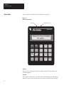
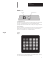
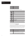
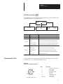
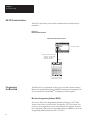
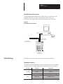
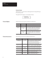
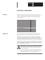
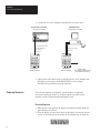
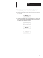
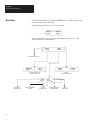
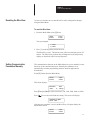
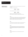
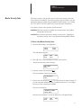
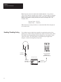
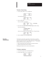
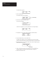
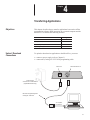
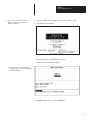

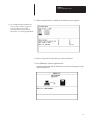
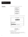
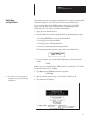
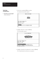
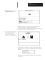
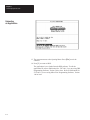
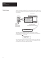
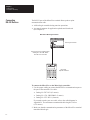
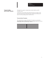
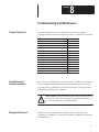
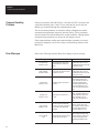
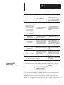
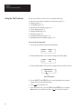
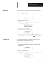
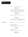
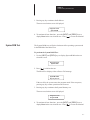
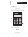
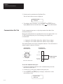
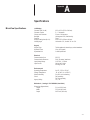
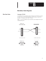
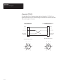
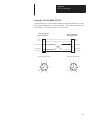
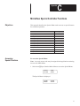
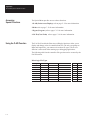
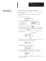
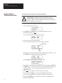
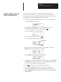
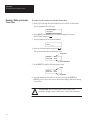
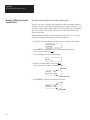
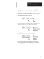
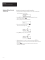
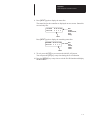
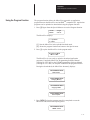


![宗像市ふれあいバス線 [1][2][3]](http://vs1.manualzilla.com/store/data/006567320_3-5f9dc7731fc64c7a331fe5e430321b0a-150x150.png)