1
Freescale Semiconductor, Inc.
ARCHIVED BY FREESCALE SEMICONDUCTOR, INC. 2005
Freescale Semiconductor, Inc...
ARCHIVED BY FREESCALE SEMICONDUCTOR, INC. 2005
Embedded SDK
(Software Development Kit)
Type 1 and 2 Telephony Features Library
SDK140/D
Rev. 1, 07/23/2002
© Motorola, Inc., 2002. All rights reserved.
For More Information On This Product,
Go to: www.freescale.com
Freescale Semiconductor, Inc.
ARCHIVED BY FREESCALE SEMICONDUCTOR, INC. 2005
Freescale Semiconductor, Inc...
ARCHIVED BY FREESCALE SEMICONDUCTOR, INC. 2005
For More Information On This Product,
Go to: www.freescale.com
Freescale Semiconductor, Inc.
ARCHIVED BY FREESCALE SEMICONDUCTOR, INC. 2005
Contents
Audience . . . . . . . . . . . . . . . . . . . . . . . . . . . . . . . . . . . . . . . . . . . . . . . . . . . . . . . . . ix
Organization . . . . . . . . . . . . . . . . . . . . . . . . . . . . . . . . . . . . . . . . . . . . . . . . . . . . . . ix
Suggested Reading . . . . . . . . . . . . . . . . . . . . . . . . . . . . . . . . . . . . . . . . . . . . . . . . . ix
Conventions . . . . . . . . . . . . . . . . . . . . . . . . . . . . . . . . . . . . . . . . . . . . . . . . . . . . . . . x
Definitions, Acronyms, and Abbreviations . . . . . . . . . . . . . . . . . . . . . . . . . . . . . . . x
References. . . . . . . . . . . . . . . . . . . . . . . . . . . . . . . . . . . . . . . . . . . . . . . . . . . . . . . . xi
ARCHIVED BY FREESCALE SEMICONDUCTOR, INC. 2005
Freescale Semiconductor, Inc...
About This Document
Chapter 1
Introduction
1.1 Quick Start. . . . . . . . . . . . . . . . . . . . . . . . . . . . . . . . . . . . . . . . . . . . . . . . . . . . . . . . . 1-1
1.2 Telephony Features Libraries . . . . . . . . . . . . . . . . . . . . . . . . . . . . . . . . . . . . . . . . . . 1-1
1.3 Overview of the Type 1 and 2 Telephony Features Library . . . . . . . . . . . . . . . . . . . 1-2
1.3.1
Overview of Type 1 Functionality . . . . . . . . . . . . . . . . . . . . . . . . . . . . . . . . . . . . 1-2
1.3.1.1
Background of the Type 1 Functionality . . . . . . . . . . . . . . . . . . . . . . . . . . 1-3
1.3.2
Overview of Type 2 Functionality . . . . . . . . . . . . . . . . . . . . . . . . . . . . . . . . . . . . 1-6
1.3.2.1
Background of the Type 2 Functionality . . . . . . . . . . . . . . . . . . . . . . . . . . 1-6
1.3.3
Features and Performance . . . . . . . . . . . . . . . . . . . . . . . . . . . . . . . . . . . . . . . . . . 1-8
Chapter 2
Directory Structure
2.1
2.2
Required Core Directories. . . . . . . . . . . . . . . . . . . . . . . . . . . . . . . . . . . . . . . . . . . . . 2-1
Optional (Domain-Specific) Directories . . . . . . . . . . . . . . . . . . . . . . . . . . . . . . . . . . 2-2
Chapter 3
Type 1 and 2 Telephony Features Library Interfaces
3.1 Type 1 and 2 Telephony Features Library Interface Services . . . . . . . . . . . . . . . . . 3-1
3.2 Interface. . . . . . . . . . . . . . . . . . . . . . . . . . . . . . . . . . . . . . . . . . . . . . . . . . . . . . . . . . . 3-1
3.2.1
Variable Definition. . . . . . . . . . . . . . . . . . . . . . . . . . . . . . . . . . . . . . . . . . . . . . . . 3-4
3.3 Specifications . . . . . . . . . . . . . . . . . . . . . . . . . . . . . . . . . . . . . . . . . . . . . . . . . . . . . . 3-7
3.3.1
Type12CIDcreate . . . . . . . . . . . . . . . . . . . . . . . . . . . . . . . . . . . . . . . . . . . . . . . . . 3-8
3.3.2
Type12CIDdestroy . . . . . . . . . . . . . . . . . . . . . . . . . . . . . . . . . . . . . . . . . . . . . . . . 3-9
3.3.3
Type12CIDinit . . . . . . . . . . . . . . . . . . . . . . . . . . . . . . . . . . . . . . . . . . . . . . . . . . 3-10
3.3.4
Type12CID . . . . . . . . . . . . . . . . . . . . . . . . . . . . . . . . . . . . . . . . . . . . . . . . . . . . . 3-11
Chapter 4
Building the Type 1 and 2 Telephony Features Library
4.1
Building the Type 1 and 2 Telephony Features Library . . . . . . . . . . . . . . . . . . . . . . 4-1
MOTOROLA
Table of Contents
For More Information On This Product,
Go to: www.freescale.com
i
Freescale Semiconductor, Inc.
ARCHIVED BY FREESCALE SEMICONDUCTOR, INC. 2005
Chapter 5
Linking Applications with the Type 1 and 2 Telephony Features Library
5.1 Type 1 and 2 Telephony Features Library . . . . . . . . . . . . . . . . . . . . . . . . . . . . . . . .5-1
5.1.1
Library Sections . . . . . . . . . . . . . . . . . . . . . . . . . . . . . . . . . . . . . . . . . . . . . . . . . . 5-1
Chapter 6
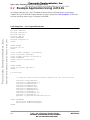
Type 1 and 2 Telephony Features Library Applications
Chapter 7
License
ARCHIVED BY FREESCALE SEMICONDUCTOR, INC. 2005
Freescale Semiconductor, Inc...
6.1 Type 2 Verification Test . . . . . . . . . . . . . . . . . . . . . . . . . . . . . . . . . . . . . . . . . . . . . . 6-1
6.1.1
Test Set-up and Procedure . . . . . . . . . . . . . . . . . . . . . . . . . . . . . . . . . . . . . . . . . . 6-1
6.2 Example Application Using cid12.lib . . . . . . . . . . . . . . . . . . . . . . . . . . . . . . . . . . . . 6-2
7.1
ii
Limited Use License Agreement. . . . . . . . . . . . . . . . . . . . . . . . . . . . . . . . . . . . . . . . 7-1
Type 1 and 2 Telephony Features Library
For More Information On This Product,
Go to: www.freescale.com
MOTOROLA
Freescale Semiconductor, Inc.
ARCHIVED BY FREESCALE SEMICONDUCTOR, INC. 2005
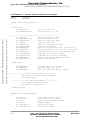
List of Tables
Type 1 and 2 Telephony Features Library Memory and MIPS Requirements . . . . . . . . . 1-8
Type12CIDcreate Arguments . . . . . . . . . . . . . . . . . . . . . . . . . . . . . . . . . . . . . . . . . . . . . . 3-8
Type12CIDdestroy Arguments . . . . . . . . . . . . . . . . . . . . . . . . . . . . . . . . . . . . . . . . . . . . . 3-9
Type12CIDinit Arguments . . . . . . . . . . . . . . . . . . . . . . . . . . . . . . . . . . . . . . . . . . . . . . . 3-10
Type12CID Arguments . . . . . . . . . . . . . . . . . . . . . . . . . . . . . . . . . . . . . . . . . . . . . . . . . . 3-11
ARCHIVED BY FREESCALE SEMICONDUCTOR, INC. 2005
Freescale Semiconductor, Inc...
1-1
3-1
3-2
3-3
3-4
MOTOROLA
List of Tables
For More Information On This Product,
Go to: www.freescale.com
iii
Freescale Semiconductor, Inc.
ARCHIVED BY FREESCALE SEMICONDUCTOR, INC. 2005
Freescale Semiconductor, Inc...
ARCHIVED BY FREESCALE SEMICONDUCTOR, INC. 2005
iv
Type 1 and 2 Telephony Features Library
For More Information On This Product,
Go to: www.freescale.com
MOTOROLA
Freescale Semiconductor, Inc.
ARCHIVED BY FREESCALE SEMICONDUCTOR, INC. 2005
List of Figures
The Functional Blocks of a Generic Type 1 and 2 Telephony Solution . . . . . . . . . . . . . .
Sequence for Delivery of FSK Data During a Call Using Type 2 CPE . . . . . . . . . . . . . .
Core Directories . . . . . . . . . . . . . . . . . . . . . . . . . . . . . . . . . . . . . . . . . . . . . . . . . . . . . . . .
cidtype12 Directory . . . . . . . . . . . . . . . . . . . . . . . . . . . . . . . . . . . . . . . . . . . . . . . . . . . . . .
cidtype12 Directory Structure . . . . . . . . . . . . . . . . . . . . . . . . . . . . . . . . . . . . . . . . . . . . . .
Example of a cid12 Library Link to a Project . . . . . . . . . . . . . . . . . . . . . . . . . . . . . . . . . .
1-5
1-7
2-1
2-2
2-2
4-1
ARCHIVED BY FREESCALE SEMICONDUCTOR, INC. 2005
Freescale Semiconductor, Inc...
1-1
1-2
2-1
2-2
2-3
4-1
MOTOROLA
List of Figures
For More Information On This Product,
Go to: www.freescale.com
v
Freescale Semiconductor, Inc.
ARCHIVED BY FREESCALE SEMICONDUCTOR, INC. 2005
Freescale Semiconductor, Inc...
ARCHIVED BY FREESCALE SEMICONDUCTOR, INC. 2005
vi
Type 1 and 2 Telephony Features Library
For More Information On This Product,
Go to: www.freescale.com
MOTOROLA
Freescale Semiconductor, Inc.
ARCHIVED BY FREESCALE SEMICONDUCTOR, INC. 2005
List of Code Examples
teldefs.h - Reference Definition for Type12CID. . . . . . . . . . . . . . . . . . . . . . . . . . . . . . . .
cid12.h - Reference Definition for Type12CID . . . . . . . . . . . . . . . . . . . . . . . . . . . . . . . .
Example of a linker.cmd File for Type 1 and 2 Telephony Features Library . . . . . . . . . .
Use of Type12CID Interface . . . . . . . . . . . . . . . . . . . . . . . . . . . . . . . . . . . . . . . . . . . . . . .
3-2
3-3
5-2
6-2
ARCHIVED BY FREESCALE SEMICONDUCTOR, INC. 2005
Freescale Semiconductor, Inc...
3-1
3-2
5-1
6-1
MOTOROLA
List of Code Examples
For More Information On This Product,
Go to: www.freescale.com
vii
Freescale Semiconductor, Inc.
ARCHIVED BY FREESCALE SEMICONDUCTOR, INC. 2005
Freescale Semiconductor, Inc...
ARCHIVED BY FREESCALE SEMICONDUCTOR, INC. 2005
viii
Type 1 and 2 Telephony Features Library
For More Information On This Product,
Go to: www.freescale.com
MOTOROLA
Freescale Semiconductor, Inc.
ARCHIVED BY FREESCALE SEMICONDUCTOR, INC. 2005
About This Document
This manual describes the Type 1 and 2 Telephony Features Library for use with Motorola’s Embedded
Software Development Kit (SDK).
ARCHIVED BY FREESCALE SEMICONDUCTOR, INC. 2005
Freescale Semiconductor, Inc...
Audience
This document targets software developers implementing communication features for analog telephone
lines.
Organization
This manual is arranged in the following sections:
•
•
•
•
•
•
•
Chapter 1, Introduction—provides a brief overview of this document
Chapter 2, Directory Structure—provides a description of the required core directories
Chapter 3, Type 1 and 2 Telephony Features Library Interfaces—describes all of the Type 1
and 2 Telephony Features Library functions
Chapter 4, Building the Type 1 and 2 Telephony Features Library—tells how to build a test
application project with the pre-built Type 1 and 2 Telephony Features Library
Chapter 5, Linking Applications with the Type 1 and 2 Telephony Features
Library—describes linking projects with the Type 1 and 2 Telephony Features Library
Chapter 6, Type 1 and 2 Telephony Features Library Applications—describes the use of the
Type 1 and 2 Telephony Features Library through test/demo applications
Chapter 7, License—provides the license required to use this product
Suggested Reading
We recommend that you have a copy of the following references:
•
•
•
Motorola DSP56800E Reference Manual, DSP56800ERM/D
Motorola DSP568xx User’s Manual, for the DSP device you’re implementing
Inside CodeWarrior: Core Tools, Metrowerks Corp.
MOTOROLA
Preface
For More Information On This Product,
Go to: www.freescale.com
ix
Freescale Semiconductor, Inc.
ARCHIVED BY FREESCALE SEMICONDUCTOR, INC. 2005
Conventions
This document uses the following notational conventions:
ARCHIVED BY FREESCALE SEMICONDUCTOR, INC. 2005
Freescale Semiconductor, Inc...
Typeface,
Symbol or Term
Meaning
Examples
Courier
Monospaced
Type
Code examples
//Process command for line flash
Italic
Directory names
Project names
Calls
Functions
Statements
Procedures
Routines
Arguments
File names
Applications
Variables
Directives
Code snippets in text
...and contains these core directories:
applications contains applications software...
Bold
Reference sources
Paths
Emphasis
...refer to the Targeting DSP5685x Platform
manual....
...see: C:\Program Files\Motorola\Embedded
SDK\help\tutorials
ALL CAPITAL
LETTERS
# defines/
Defined constants
# define INCLUDE_STACK_CHECK
Brackets [...]
Function keys
...by pressing function key [F7]
Quotation
marks, “...”
Returned messages
...the message, “Test Passed” is displayed....
...CodeWarrior project, 3des.mcp is...
...the pConfig argument....
...defined in the C header file, aec.h....
...if unsuccessful for any reason, it will return
“NULL”...
Blue Text
Linkable on-line
...refer to Chapter 7, License....
Number
Any number is considered
a positive value, unless
preceded by a minus symbol to signify a negative
value
3V
-10
DES-1
Definitions, Acronyms, and Abbreviations
The following list defines the acronyms and abbreviations used in this document. As this template
develops, this list will be generated from the document. As we develop more group resources, these
acronyms will be easily defined from a common acronym dictionary. Please note that while the acronyms
are in solid caps, terms in the definition should be initial capped ONLY IF they are trademarked names or
proper nouns.
ACK
x
Acknowledgement signal
Type 1 and 2 Telephony Features Library
For More Information On This Product,
Go to: www.freescale.com
MOTOROLA
Freescale Semiconductor, Inc.
ARCHIVED BY FREESCALE SEMICONDUCTOR, INC. 2005
Analog-to-Digital Converter
ARCHIVED BY FREESCALE SEMICONDUCTOR, INC. 2005
Freescale Semiconductor, Inc...
ADC
AGC
Automatic Gain Control
API
Application Programming Interface
ASCII
American Standard Code for Information Interchange
BPF
Bandpass Filter
CAS
Customer premises equipment Alerting Signal
CID
Caller ID (Calling Party Name and/or Number Identification)
CIDCW
Calling Identity Delivery on Call Waiting
CO
Central Office; CO often refers to the PSTN switching system, less often refers
to other equipment at the central Office location.
CPE
Customer Premises (telephony) Equipment
CQ
Call Qualifier
CWD
Call Waiting Deluxe
DAA
Data Access Arrangement
DSP
Digital Signal Processor or Digital Signal Processing
DTMF
Dual Tone Multiple Frequency signal
FSK
Frequency Shift Keying modulation
IDE
Integrated Development Environment
LEC
Line Echo Canceller
LPF
Low Pass Filter
MDMF
Multiple Data Message Format of GR-30-CORE
MIPS
Million Instructions Per Second
OnCE™
On-Chip Emulation
PC
Personal Computer
PCM
Pulse Code Modulation
PSTN
Public Switched Telephone Network
SDK
Software Development Kit
SDMF
Single Data Message Format of GR-30-CORE
SRC
Source
VMWI
Visual Message Waiting Indicator
References
The following sources were referenced to produce this book:
1.
2.
3.
4.
5.
Motorola DSP56800E Reference Manual, DSP56800ERM/D
Motorola DSP568xx User’s Manual, for the DSP device you’re implementing
Targeting Motorola DSP568xx Platform, for the DSP device you’re implementing
Motorola Embedded SDK Programmer’s Guide, SDK101/D
SR-3004, Testing Guidelines for Analog Type 1, 2, and 3 CPE as Described in
SR-INS-002726 (a module of ADSI, FR-12), Telcordia Technologies, January 1995.
MOTOROLA
Preface
For More Information On This Product,
Go to: www.freescale.com
xi
Freescale Semiconductor, Inc.
6.
7.
8.
9.
10.
12.
ARCHIVED BY FREESCALE SEMICONDUCTOR, INC. 2005
Freescale Semiconductor, Inc...
11.
xii
ARCHIVED BY FREESCALE SEMICONDUCTOR, INC. 2005
GR-30-CORE, LSSGR: Voiceband Data Transmission Interface Section 6.6 (a module of
LSSGR, FR-64), Telcordia Technologies, December 1998.
GR-31-CORE, LSSGR CLASSSM Feature: Calling Number Delivery (FSD 01-02-1051) (a
module of LSSGR, FR-64), Telcordia Technologies, June 2000.
GR-1188-CORE, LSSGR CLASSSM Feature: Calling Name Delivery Generic
Requirements (FSD 01-02-1070) (a module of LSSGR, FR-64), Telcordia Technologies,
December 2000.
GR-1401-CORE, LSSGR CLASSSM Feature: Visual Message Waiting Indicator Generic
Requirements (FSD 01-02-2000) (a module of LSSGR, FR-64), Telcordia Technologies,
June 2000.
GR-575-CORE, LSSGR CLASSSM Feature Calling Identity Delivery on Call Waiting, FSD
01-02-109 (a module of LSSGR, FR-64), Telcordia Technologies, June 2000.
GR-416-CORE, CLASSSM Feature Call Waiting Deluxe, FSD 01-02-1215, (a module of
LSSGR, FR-64), Telcordia Technologies, December 1999.
ITU-T Recommendation V.23, (11/88) - 600/1200-baud modem standardized for use in the
general switched telephone network.
Type 1 and 2 Telephony Features Library
For More Information On This Product,
Go to: www.freescale.com
MOTOROLA
Freescale Semiconductor, Inc.
ARCHIVED BY FREESCALE SEMICONDUCTOR, INC. 2005
Welcome to Motorola’s family of Digital Signal Processors, or DSPs. This document describes the Type 1
and 2 Telephony Features Library, which is a part of Motorola’s comprehensive Software Development
Kit, SDK, for its DSPs. In this document, you will find all the information required to use and maintain the
Type 1 and 2 Telephony Features Library interface and algorithms.
ARCHIVED BY FREESCALE SEMICONDUCTOR, INC. 2005
Freescale Semiconductor, Inc...
Chapter 1
Introduction
Motorola provides these algorithms to you under license for use with Motorola DSPs to expedite your
application development and reduce the time it takes to bring your own products to market.
Motorola’s Type 1 and 2 Telephony Features Library is a licensed software library for use on Motorola
DSP56800E series processors. Please refer to the Software License Agreement in Chapter 7 for license
terms and conditions.
1.1 Quick Start
Motorola’s Embedded SDK is targeted to a large variety of hardware platforms. To take full advantage of
a particular hardware platform, use Quick Start from the Targeting Motorola DSP5685x Platform documentation.
For example, the Targeting Motorola DSP5685x Platform manual provides more specific information
and examples about this hardware architecture. If you are developing an application for the
DSP56858EVM board, or any other DSP56858 development system, refer to the Targeting Motorola
DSP5685x Platform manual for Quick Start or other DSP56858-specific information.
Note:
“DSP568xx” refers to the specific device for which you’re developing, as shown in the
preceding example.
1.2 Telephony Features Libraries
The Type 1 and 2 Telephony Features Library is one of a set of Motorola Embedded SDK modules and
applications consisting of the following:
•
•
•
•
Type 1 Telephony Features Library
Type 1 and 2 Telephony Features Library
Type 1 and 2 Telephony Parser Library
Full Duplex Speakerphone Library
MOTOROLA
Introduction
For More Information On This Product,
Go to: www.freescale.com
1-1
Introduction
•
•
Freescale Semiconductor, Inc.
ARCHIVED BY FREESCALE SEMICONDUCTOR, INC. 2005
Generic Echo Canceller Library
Feature Phone Application Software
These modules are designed to interoperate, providing all software necessary to implement a feature phone
with full duplex speakerphone and Type 1 and 2 Caller ID functionality. By using some or all of these
modules, several other types of telephony applications are also possible. Each module may also be used
independently.
ARCHIVED BY FREESCALE SEMICONDUCTOR, INC. 2005
Freescale Semiconductor, Inc...
1.3 Overview of the Type 1 and 2 Telephony
Features Library
The Type 1 and 2 Telephony Features Library can handle both on-hook Caller ID and related information
reception services, known as Type 1 services, and off-hook Caller ID and related services, known as Type
2 services. The following sections provide an overview, first of the Type 1 functionality of the Type 1 and
2 Telephony Features Library, then of its Type 2 functionality.
1.3.1 Overview of Type 1 Functionality
Customer Premises Equipment (CPE) using the Type 1 and 2 Telephony Features Library has the features
to support existing on-hook Caller ID services, such as Calling Number Delivery and Calling Name Delivery; other existing on-hook services, such as Visual Message Waiting Indicator (VMWI) or Call Qualifier
(CQ); as well as future services that would use the on-hook GR-30-CORE Voiceband Data Transmission
Interface from the Public Switched Telephone Network (PSTN). Type 1 CPE supports on-hook signaling
with or without power ringing and can decode data frames packaged in the GR-30-CORE Single Data
Message Format (SDMF) or Multiple Data Message Format (MDMF), depending on the needs of the specific telephony service supported, as described in Telcordia SR-3004 and other referenced service-specific
documents.
While this module is primarily intended to be used for Caller ID reception, other convenient features have
been added to allow for simple integration into a Caller ID telephone. While the module is in an on-hook
state, ring generator samples may be created during power ringing. These samples may be output to an
audio channel (for example, to be played to a speaker). While the module is in an off-hook state, DTMF
samples may be generated for dialing digits. Timing for a line flash is also provided.
The Caller ID is received between the first and second ring. The content displayed should include date,
time, and the directory telephone number and/or the name of the caller. Other existing service-specific content may also be displayed, such as Call Qualifier displays. The service-specific content of future services
may be displayed when these become deployed in the PSTN.
VMWI may be transmitted with or without power ringing, but must be received without power ringing.
The CPE is instructed by the data received in GR-30-CORE format to turn a light or other visual indicator
on or off, indicating that new messages have been received at a voice mail system or other messaging service.
The performance of CPE incorporating the Type 1 and 2 Telephony Features Library will comply with the
transmission layer performance requirements of Telcordia SR-3004, including those for:
1-2
Type 1 and 2 Telephony Library
For More Information On This Product,
Go to: www.freescale.com
MOTOROLA
FreescaleOverview
Semiconductor,
Inc.
of the Type 1 and 2 Telephony Features Library
•
•
•
•
ARCHIVED BY FREESCALE SEMICONDUCTOR, INC. 2005
Freescale Semiconductor, Inc...
•
•
ARCHIVED BY FREESCALE SEMICONDUCTOR, INC. 2005
Frequency Shift Keying (FSK) modulation sensitivity
Twist, or level differences between FSK signal tones
FSK frequencies and variation from their nominal values
— In addition to complying with the FSK modulation frequencies of SR-3004, the Type 1 and 2
Telephony Features Library can also detect FSK transmitted using the slightly different
frequencies specified by the ITU-T V.23 modem recommendation. However, the Type 1 and 2
Telephony Features Library cannot be used directly in equipment for international telephone
networks with V.23, since the timing protocols are likely different.
Robust detection of incoming FSK signals in the presence of significant noise impairments on the
telephone line
All signal and inter-signal timings required in SR-3004, with or without power ringing
The ability to receive FSK after detecting power ringing signals which have any of the various
cadences required by SR-3004, in addition to the Normal ringing pattern
1.3.1.1 Background of the Type 1 Functionality
The on-hook Type 1 Library is basically a Frequency Shift Keying (FSK) receiver with the following additional abilities:
•
•
•
to detect power ringing
to recognize and remain immune to various other voltage level shifts identified in SR-3004 that may
precede FSK data with or without power ringing
to recognize the start of FSK data reception
— following various other voltage level shifts identified in SR-3004 and power ringing
— following only various other voltage level shifts identified in SR-3004 (power ringing does not
precede FSK data)
— if not preceded by any of the various other voltage level shifts identified in SR-3004
Thus, required inputs to this Library are:
•
Indication of power ringing
— Usually present before reception of Caller ID in FSK data
— Usually absent before reception of VMWI in FSK data
— Used by the Library to disable the FSK receiver during power ringing
•
•
Indication of Open Switching Intervals (OSIs) or other voltage level shifts that may precede the
FSK data
The FSK data in the GR-30-CORE format appropriate for Calling Number Delivery, Calling Name
Delivery, VMWI, or other existing or future telephony service
A line interface is needed to detect the presence of a power ringing signal. The line interface can be a Data
Access Arrangement (DAA) or any line interface that can pass FSK signals from the telephone network
and has a ring detect circuit that can indicate to the DSP that a power ringing signal has been received. The
line interface circuitry may vary, depending on the individual case.
For the Type 1 and 2 Telephony Features Library to comply with Telcordia SR-3004 requirements, the user
must supply a suitable line interface that meets the following requirements:
•
Frequency Response--The received signal must be within voice (also called line) bandwidth, which
ranges from 300 to 3400Hz
MOTOROLA
Introduction
For More Information On This Product,
Go to: www.freescale.com
1-3
Introduction
•
Freescale Semiconductor, Inc.
ARCHIVED BY FREESCALE SEMICONDUCTOR, INC. 2005
Attenuation Distortion (Front End Range)--The Type 1 and 2 Telephony Features Library is
designed to interoperate with an Analog-to-Digital Converter (ADC) with an analog signal input
range of 2.73dBm±3dB. In other words, the ADC in the line front end should have a 3V
peak-to-peak analog input voltage range.
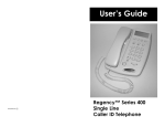
The rest of this section describes the system-level operation of a generic FSK receiver, the major component of this Library. Figure 1-1 provides a high-level example of a generic FSK receiver used in the Type
1 and 2 Telephony Features Library. The FSK receiver is shown inside the dashed lines in Figure 1-1. The
components shown outside the dashed lines are not supplied with the Type 1 and 2 Telephony Features
Library.
ARCHIVED BY FREESCALE SEMICONDUCTOR, INC. 2005
Freescale Semiconductor, Inc...
In one possible implementation using the Motorola DSP56858EVM board, the ring signal indication from
the line interface must pass to the DSP56858EVM on one of the DSP’s GPIOB pins. The signal from the
line interface can be passed to the DSP56858EVM using a stereo jack. Details of required jumper settings
are contained in the DSP56858 Evaluation Module User’s Manual.
1-4
Type 1 and 2 Telephony Library
For More Information On This Product,
Go to: www.freescale.com
MOTOROLA
FreescaleOverview
Semiconductor,
Inc.
of the Type 1 and 2 Telephony Features Library
ARCHIVED BY FREESCALE SEMICONDUCTOR, INC. 2005
Tip
Ring
DAA
ADC
BPF
Demodulator
ARCHIVED BY FREESCALE SEMICONDUCTOR, INC. 2005
Freescale Semiconductor, Inc...
AGC
Functional
Blocks of a
Generic FSK
Receiver
LPF
Slicer
Decision Maker
Framing
Parser
Screen
Hour : Minute
Month : Day
Number
Name
Figure 1-1. The Functional Blocks of a Generic Type 1 and 2 Telephony Solution
The FSK receiver performs noise filtering, signal detection, demodulation, and framing, then passes Caller
ID (or VMWI, etc.) to the application layer to display on the CPE. The FSK receiver is always enabled, so
it can receive VMWI without power ringing. If receiving Caller ID, power ringing will be signaled to the
DSP to disable the FSK receiver during the ringing. The digital samples must be collected with an ADC at
the sampling rate of 8KHz, with a minimum of 14-bit linear precision (8-bit µ-law). The ADC is not part of
this solution and must be supplied separately by the application developer; however, the DSP56858EVM
board contains an ADC. The FSK receiver starts processing the digital samples received as soon as the
ADC sends them. The FSK receiver accepts an FSK signal transmitting at a baud rate of 1200bps according to Telcordia Technologies SR-3004.
MOTOROLA
Introduction
For More Information On This Product,
Go to: www.freescale.com
1-5
Introduction
Freescale Semiconductor, Inc.
ARCHIVED BY FREESCALE SEMICONDUCTOR, INC. 2005
The digital samples from the ADC will first pass through a bandpass filter (BPF) as shown in Figure 1-1,
where only the signals within line bandwidth (300 – 3400Hz) can be passed. The BPF output will be processed in an Automatic Gain Control (AGC) function. The AGC estimates the signal level to compensate
for the amplitude distortions introduced by the telephone network. In addition, the estimated power level is
used for signal detection. The AGC output sample is then sent to a software demodulator.
ARCHIVED BY FREESCALE SEMICONDUCTOR, INC. 2005
Freescale Semiconductor, Inc...
The demodulator will introduce a double frequency component. The following low pass filter (LPF) is
used to remove the double frequency component and pass signals within the sample frequency range. The
outputs of the demodulator are sent to the Slicer, where timing recovery is performed and a decision for a
symbol is made. The symbols are then framed to form an ASCII word. The ASCII words are passed to
upper-layer functionality external to the Type 1 and 2 Telephony Features Library for parsing and displaying Caller ID information, or for activating/deactivating the VMWI.
The user must supply a parser algorithm external to this Type 1 and 2 Telephony Features Library to
decode the message layer ASCII words according to the appropriate service-dependent GR-30-CORE format - either SDMF or MDMF - in a manner compliant with the message layer requirements of SR-3004.
See References for the format applicable to each service that uses the GR-30-CORE protocol supported by
the Type 1 and 2 Telephony Features Library. The Parser Library supplied with the Embedded SDK is the
preferred method for interoperating with the Type 1 and 2 Telephony Features Library to achieve both
transmission layer and message layer SR-3004 compliance.
1.3.2 Overview of Type 2 Functionality
Type 2 CPE has all the features of Type 1, plus the feature of supporting off-hook Caller ID. In other
words, Type 2 CPE can also process Caller ID during a call. Unlike Type 1, Type 2 CPE can receive multiple Caller IDs one at a time during a call. Type 2 CPE, therefore, has the features to support existing
off-hook Caller ID services, such as Calling Identity Delivery on Call Waiting (CIDCW) and Call Waiting
Deluxe (sometimes called Call Waiting with Call Disposition). These services use the GR-30-CORE
MDMF over FSK. The Caller ID contents should include date, time, number and/or the name of the caller.
The Type 2 performance of CPE that incorporate this Type 1 and 2 Telephony Features Library (also called
the Type12CID Module or just the Type 12 Module) is compliant with the Type 1 transmission layer
requirements of Telcordia SR-3004 mentioned in Section 1.3.1, and with the Type 2 transmission layer
requirements of Telcordia SR-3004, including those for:
•
•
•
Frequency Shift Keying (FSK) modulation sensitivity
Twist, or level differences between FSK signal tones
FSK frequencies and variation from their nominal values
— In addition to complying with the FSK modulation frequencies of SR-3004, the Type 1 and 2
Telephony Features Library can also able detect FSK transmitted using the slightly different
frequencies specified by the ITU-T V.23 modem recommendation
•
Robust detection of incoming Caller ID or VMWI signals in the presence of significant noise
impairments on the telephone line
All Subscriber Alerting Signal (SAS), CPE Alerting Signal (CAS), DTMF signal, FSK signal, and
inter-signal timings required in SR-3004, which will be described in more detail in the next section
•
1.3.2.1 Background of the Type 2 Functionality
The Type 2 Caller ID service is also known as Calling Identity Delivery on Call Waiting (CIDCW). During a conversation between two parties, CIDCW occurs if a third party calls one of the two parties. If the
1-6
Type 1 and 2 Telephony Library
For More Information On This Product,
Go to: www.freescale.com
MOTOROLA
FreescaleOverview
Semiconductor,
Inc.
of the Type 1 and 2 Telephony Features Library
ARCHIVED BY FREESCALE SEMICONDUCTOR, INC. 2005
Freescale Semiconductor, Inc...
ARCHIVED BY FREESCALE SEMICONDUCTOR, INC. 2005
party called is using a Type 2 CPE, an SAS or call waiting tone will be received along with the dual tone
CAS. If the Type 2 CPE detects no other extensions in use, it will acknowledge the CAS with a DTMF-D
signal, used by Type 2 CPE for handshaking purposes with the Central Office (CO) upon reception of a
CAS signal. The PSTN will send the Caller ID information via FSK transmission. If the CPE receives the
FSK data correctly, the CPE will display the Caller ID information. The following paragraph describes the
handshaking sequence for a Type 2 CPE receiving FSK data in the off-hook state.
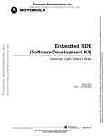
The SAS is sent to the called party along with the CAS from the PSTN CO, i.e., the call-terminating
switching system, to request that the line be cleared of conversation to allow the delivery of the FSK data.
The CO switch has momentarily muted the far-end party before sending the SAS and CAS. Upon receiving
a CAS, the Type 2 CPE will test to determine if parallel handsets are in use. If so, no acknowledgement
signal (ACK) will be returned to the CO and the FSK data will not be delivered. If no parallel handsets are
in use, the Type 2 CPE will mute the CPE handset and send an ACK consisting of a DTMF-D to the CO.
Muting the handset prevents noise or side tones from interfering with the receipt of FSK data and prevents
the user from hearing the FSK transmission. Upon receiving the DTMF-D tone, the CO sends the FSK data
to the CPE and reconnects the far end upon conclusion. After receiving the FSK data, the CPE unmutes the
handset. Figure 1-2 shows the sequence of handshakes between the CO and the Type 2 CPE.
Type 2 CPE in
off-hook
CO
CAS
Check
parallel
handset; if not in
use, mute handset
and send ACK back
CO sends CAS to
CPE for Caller ID
delivery
ACK
Caller ID
Upon received ACK
signal, CO sends
Caller ID
After the complete
Caller ID is received,
the
handset
is
unmuted
Figure 1-2. Sequence for Delivery of FSK Data During a Call Using Type 2 CPE
The main difference between the Type 1 and 2 Telephony Features Library and the separate Type 1 Telephony Features Library is that the Type 1 and 2 Telephony Features Library supports both on- and off-hook
FSK data reception, while the Type 1 Telephony Features Library supports only on-hook FSK data reception. The processing and requirements of the Type 1 and 2 Telephony Features Library to support Type 1
on-hook FSK data reception are the same as that of the Type 1 Telephony Features Library which is
described in Section 1.3.1. However, in the off-hook state, when Type 2 CPE provides CIDCW functionality, an extension-in-use check is performed to determine if there are any parallel extensions off-hook
before acknowledging back to the CO with a DTMF-D signal. To support off-hook FSK data reception, the
Triple Data Encryption Standard (3DES) Library requires an indication from the Line Interface to indicate
the on-hook or off-hook state of any extensions in parallel with the Type 2 CPE.
The following text describes additional functions needed for Type 2 CPE supporting off-hook Caller ID:
MOTOROLA
Introduction
For More Information On This Product,
Go to: www.freescale.com
1-7
Introduction
Freescale Semiconductor, Inc.
ARCHIVED BY FREESCALE SEMICONDUCTOR, INC. 2005
Supporting off-hook Caller ID requires a CAS detector and Line Echo Canceller (LEC). The LEC cancels
the side tone to the line input so that CPE can receive a clear CAS signal and accurately detect the FSK
data. For details, see the Generic Echo Canceller Library, which contains a description of the LEC.
When the CAS is detected, if no extensions are found to be in use, the Type 1 and 2 Telephony Features
Library mutes the voice path and keypad, sends a DTMF D signal to the PSTN to request FSK data delivery, then enables the Module’s FSK receiver. The FSK data received is processed in the FSK receiver. The
operation of the FSK receiver, parser, and display functions are identical to Type 1 Caller ID reception,
described in Section 1.3.1.
ARCHIVED BY FREESCALE SEMICONDUCTOR, INC. 2005
Freescale Semiconductor, Inc...
When the Type 1 and 2 Telephony Features Library is running in the off-hook state, every sample must be
tested for detection of the CAS. The process of CAS detection includes frequency filtering, power estimation, and threshold detection. The CAS is the combination of two frequencies, 2130Hz and 2750Hz, so two
filters are needed for detecting the frequencies: one bandpass filter for 2130Hz and one bandpass filter for
2750Hz. Signals passed by these two bandpass filters are estimated for power level. In order to define that
a CAS has been detected, the power level must exceed a pre-defined threshold.
1.3.3 Features and Performance
Table 1-1 details the memory and MIPS requirements for the Type 1 and 2 Telephony Features Library.
Table 1-1. Type 1 and 2 Telephony Features Library Memory and MIPS Requirements
Type 1 and 2 Telephony
Features Library
1-8
Program
Memory
(ROM)
(16 bit
words)
Data ROM
(16 bit
words)
Data RAM
1st Instance
(16 bit
words)
Data RAM
Additional
Instance
(16 bit
words)
MIPS
(When all program
and data is internal
memory)
2.8 K
20
257
192
9.6
Type 1 and 2 Telephony Library
For More Information On This Product,
Go to: www.freescale.com
MOTOROLA
Freescale Semiconductor, Inc.
ARCHIVED BY FREESCALE SEMICONDUCTOR, INC. 2005
Chapter 2
Directory Structure
ARCHIVED BY FREESCALE SEMICONDUCTOR, INC. 2005
Freescale Semiconductor, Inc...
Note:
“DSP568xx” refers to the specific device for which you’re developing, as shown in Chapter 1,
“Introduction.” .
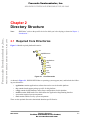
2.1 Required Core Directories
Figure 2-1 details required platform directories:
src
dsp568xxevm
nos
+
applications
+
bsp
config
include
+
sys
+
tools
Figure 2-1. Core Directories
As shown in Figure 2-1, DSP56858EVM has no operating system support (nos), and includes the following core directories:
•
•
•
•
•
•
applications contains applications software that can be exercised on this platform
bsp contains board support package specific for this platform
config contains default hardware and software configurations for this platform
include contains SDK header files which define the Application Programming Interface
sys contains required system components
tools contains utilities used by system components
There are also optional directories that include domain-specific libraries.
MOTOROLA
Directory Structure
For More Information On This Product,
Go to: www.freescale.com
2-1
Directory Structure
Freescale Semiconductor, Inc.
ARCHIVED BY FREESCALE SEMICONDUCTOR, INC. 2005
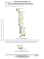
2.2 Optional (Domain-Specific) Directories
Figure 2-2 shows the domain-specific directory, cidtype12.
dsp568xxevm
nos
+
applications
+
bsp
config
ARCHIVED BY FREESCALE SEMICONDUCTOR, INC. 2005
Freescale Semiconductor, Inc...
include
+
modem
+
multimedia
+
security
+
signal
+
speech
+
sys
telephony
+
aec
+
caller_id
+
cas_detect
+
cidparse
+
cidtype1
cidtype12
Debug
test
+
cpt
+
Figure 2-2. cidtype12 Directory
The telephony directory, shown in Figure 2-3, includes specific vocoder algorithms, such as G.726, as well
as cidtype12, the directory that includes the Type 1 Telephony Features Library for receiving off-hook
Caller ID and other services. The cidtype12 directory includes Type 1 and 2 interface algorithms.
cidtype12
Debug
test
configintram
Figure 2-3. cidtype12 Directory Structure
2-2
Type 1 and 2 Telephony Library
For More Information On This Product,
Go to: www.freescale.com
MOTOROLA
Freescale Semiconductor,
Inc.
Optional (Domain-Specific) Directories
ARCHIVED BY FREESCALE SEMICONDUCTOR, INC. 2005
The cidtype12 directory shown in Figure 2-3 includes:
•
•
Debug contains the library file (cid1.lib) for the prebuilt Type 1 Telephony Features Library
test contains the test project cid1test.mcp for the prebuilt Type 1 Telephony Features Library
— contains C source for the test application
ARCHIVED BY FREESCALE SEMICONDUCTOR, INC. 2005
Freescale Semiconductor, Inc...
— configintram contains the linker.cmd file for the test application and also contains appconfig.c
and appconfig.h to override the SDK’s config.h for this particular project
MOTOROLA
Directory Structure
For More Information On This Product,
Go to: www.freescale.com
2-3
Directory Structure
Freescale Semiconductor, Inc.
ARCHIVED BY FREESCALE SEMICONDUCTOR, INC. 2005
Freescale Semiconductor, Inc...
ARCHIVED BY FREESCALE SEMICONDUCTOR, INC. 2005
2-4
Type 1 and 2 Telephony Library
For More Information On This Product,
Go to: www.freescale.com
MOTOROLA
Freescale Semiconductor, Inc.
ARCHIVED BY FREESCALE SEMICONDUCTOR, INC. 2005
Chapter 3
Type 1 and 2 Telephony Features
Library Interfaces
ARCHIVED BY FREESCALE SEMICONDUCTOR, INC. 2005
Freescale Semiconductor, Inc...
The Type 1 and 2 Telephony Features Library is defined as:
Type12CID.lib
The service, interface, and function calls included are described in this chapter.
3.1 Type 1 and 2 Telephony Features Library
Interface Services
The Type 1 and 2 Telephony Features Library interface provides Caller ID, Visual Message Waiting
Indicator (VMWI), and other related services, which occur in the on-hook or off-hook state. The Type 1
and 2 Telephony Features Library supports FSK signals with a baud rate of 1200bps. The library
demodulates the FSK into ASCII words and passes the data payload to the application program for
processing and presentation. The FSK message can be in single or multiple data message format per
Telcordia SR-3004. In the on-hook state, the actual FSK message is received between the first and second
ring. If an FSK message is not detected during this period, no information will be available until the next
call. Other services, such as VMWI, may not involve power ringing at all. In the off-hook state, the Type 1
and 2 Telephony Features Library detects CAS tones and generates the DTMF D acknowledgement signal
to the PSTN switching system for Caller ID delivery. FSK data received in the off-hook state uses the
multiple data message format (MDMF), as described in Telcordia SR-3004 and other references describing
CIDCW and CWD.
3.2 Interface
The Type 1 and 2 Telephony Features Library can be called by an application program in C. Code
Example 3-1 contains structure definitions of teldef_sControl and teldef_sSamples which are used by the
Type 1 and 2 Telephony Features Library to receive information from the application and then to output
results to the application. A listing of the variables in teldefs.h that are related to the Type 1 and 2
Telephony Features Library only is included; other variables are described in their respective library
documents.
MOTOROLA
Type 1 and 2 Telephony Features Library Interfaces
For More Information On This Product,
Go to: www.freescale.com
3-1
Freescale Semiconductor, Inc.
Type 1 and 2 Telephony Features Library Interfaces
ARCHIVED BY FREESCALE SEMICONDUCTOR, INC. 2005
Code Example 3-1. teldefs.h - Reference Definition for Type12CID
#ifndef
#define
__TELDEFS_H
__TELDEFS_H
typedef struct teldefs_tsControl
{
ARCHIVED BY FREESCALE SEMICONDUCTOR, INC. 2005
Freescale Semiconductor, Inc...
// phone state.
int hookSwitch;
int handsFreeLayer1;
//on hook or off hook.
//speaker phone on or off.
//------------------- Caller ID.-------------------------int intpdata;
//pointer for modular buffer.
int cidRingPolarity;
//ring signal high or low.
int cidByteReady;
//flag for a byte when ready.
int cidByte;
//contents of the byte.
int messageDone;
//flag for a message when ready.
int messageLength;
//length of the message.
int ExtUseCheck;
//set by the library for an ext. in use check.
int NoExtFound;
//set by the application for an ext. in use check.
int FrameErrors;
//indicates if frame error occurred during fsk.
int flashCommand;
//indicates line should be flashed.
int flashPolarity;
//indicates the direction of flashing.
int cwdCommand;
//begin a Call Waiting deluxe pulse/dial.
int disableRinger;
//disable ring generator.
// DTMF dialer
int dtmfRequest;
int dtmfDigit;
int dtmfComplete;
//to dial a dtmf. ON = 1, OFF = 0.
//the dtmf digit to be dialed.
//flag for a dtmf when dialing complete.
//---------------- Generic Echo Canceller ----------------//Generic Echo Canceller related variables
//are declared here.
//--------------- Full Duplex Speakerphone ---------------//Full Duplex Speakerphone related
//variables are declared here.
} teldefs_sControl;
typedef struct teldefs_tsSamples
{
int line[5];
int audio[5];
int gec[5];
int aec[5];
int voipinput[5];
int voipoutput[5];
3-2
//line input or audio output.
//audio input or line output.
//generic echo canceller’s output.
//fdspk’s output.
//third port’s input.
//third port’s output.
Type 1 and 2 Telephony Features Library
For More Information On This Product,
Go to: www.freescale.com
MOTOROLA
Freescale Semiconductor, Inc.
Interface
ARCHIVED BY FREESCALE SEMICONDUCTOR, INC. 2005
int leccid[5];
//used by type 2 to receive line echo cancelled
//samples.
} teldefs_sSamples;
#endif
ARCHIVED BY FREESCALE SEMICONDUCTOR, INC. 2005
Freescale Semiconductor, Inc...
The structure defined in cid12.h, cid_sData, is allocated by the Type12CIDcreate() function, but is
accessed only by the Type 1 and 2 Caller ID functions. It is essential that memory be allocated for this
structure for the Type 1 and 2 Caller ID functions to use and that no other function, or the application itself,
access the memory space reserved for this structure. The Type 1 and 2 Caller ID function stores values for
reuse, so tampering with the contents of the structure will cause the function to give erroneous results.
As shown in Code Example 3-2 and Code Example 6-1, the code must statically allocate both a
teldef_sControl and teldef_sSample structure for each instance of a Caller ID channel, while using a call to
Type12CIDcreate() to dynamically allocate the data structure.
The use of function prototypes and structure instances for the Type 1 and 2 Telephony Features Library is
described in header file cid12.h, shown in Code Example 3-2.
Code Example 3-2. cid12.h - Reference Definition for Type12CID
#ifndef
#define
__CID12_H
__CID12_H
/***************************
Foundational Include Files
****************************/
#include "cid_type12.h"
#ifndef __TELDEFS_H
#include "teldefs.h"
#endif
/*************************************************
Structures that must be defined before
accessing Type 1 and 2 Caller_ID pointer. Examples are shown below:
*************************************************/
/*
teldef_sControl
cid_sData*
teldef_sSample
*/
MOTOROLA
Line1Control
pCID12Data
Line1Samples
Type 1 and 2 Telephony Features Library Interfaces
For More Information On This Product,
Go to: www.freescale.com
3-3
Freescale Semiconductor, Inc.
Type 1 and 2 Telephony Features Library Interfaces
ARCHIVED BY FREESCALE SEMICONDUCTOR, INC. 2005
/* Local variables for Type 1 and 2 Telephony Features, size of 127. Structure _sData
details are defined in header file cid_type12.h, which also contains various space
allocators and housekeeping variables. However, since these variables are not
manipulated by the application, the contents of cid_type12.h are not documented in
this SDK. */
ARCHIVED BY FREESCALE SEMICONDUCTOR, INC. 2005
Freescale Semiconductor, Inc...
/*************************************************
Function Prototypes for Type 1 and 2 Interface Library
*************************************************/
cid_sData* Type12CIDcreate(teldef_tsControl *pControl);
int Type12CIDdestroy(cid_sData *pData, teldef_tsControl *pControl);
void Type12CIDinit(cid_sData *pData, teldef_tsControl *pControl);
void Type12CID(cid_sData *pData, teldef_tsControl *pControl, teldef_tsSample
*pSample);
#endif
3.2.1 Variable Definition
This section includes a more detailed explanation of the variables in structure teldefs_tsControl that an
application using the Type 1 and 2 Telephony Features Library must set. Also included in teldefs.h are the
data structures for the Type 1 and 2 Telephony Parser Library, needed to help display the received FSK
message. For additional information, see the document Type 1 and 2 Telephony Parser Library.
hookSwitch
Set by the application to indicate to the Type 1 and Type 1 and 2 Libraries
whether the phone is on-hook or off-hook
On-hook = 0
Off-hook = 1
handsFreeLayer1
Set by the application to indicate to the Type 1 and Type 1 and 2 Libraries
whether the handset or handsfree is enabled
intpdata
Set and allocated by Type12create() to identify the address of the modulo buffer
for FSK
cidRingPolarity
Set by the application to indicate to the Type 1 and Type 1 and 2 Libraries when a
ringing signal is detected on the ringing detect circuit. The ringing detect circuit
should be capable of detecting either the envelope of the ringing signal itself or of
a square wave whose fundamental frequency is the ring frequency. For purposes
of ringing detection, the envelope of a signal is either the amplitude of a signal or
some more slowly varying amplitude detected by less sensitive circuitry.
cidByteReady
Set by the Type 1 and Type 1 and 2 Libraries to indicate to the application (or to
the Type 1 and 2 Telephony Parser Library) that one byte is ready from the FSK
receiver
cidByte
Set by the Type 1 and Type 1 and 2 Libraries; it holds the actual byte
messageDone
Set by the Type 1 and Type 1 and 2 Libraries to indicate to the application (or
Type 1 and 2 Telephony Parser Library) that an FSK message is completed
3-4
Type 1 and 2 Telephony Features Library
For More Information On This Product,
Go to: www.freescale.com
MOTOROLA
Freescale Semiconductor, Inc.
messageLength
int ExtUseCheck
Interface
ARCHIVED BY FREESCALE SEMICONDUCTOR, INC. 2005
Set by the Type 1 and Type 1 and 2 Libraries to indicate the length of the FSK
message to the application
Set by the library to indicate to the application to do the following:
ExtUseCheck = 0
Do nothing
ExtUseCheck = 1
Go on-hook but do not change the Control.hookswitch
variable
ExtUseCheck = 2
The application should test whether an extension phone
is off-hook and set NoExtFound accordingly
If an extension CPE is found to be off-hook, clear
NoExtFound = 0; otherwise, set NoExtFound = 1
ARCHIVED BY FREESCALE SEMICONDUCTOR, INC. 2005
Freescale Semiconductor, Inc...
ExtUseCheck = 3
Go off-hook, but do not change the Control.hookswitch
variable
int NoExtFound
Set by the application (when ExtUseCheck = 2) and indicates whether an
extension phone is off-hook; this indication is used by the CID Module
FrameErrors
Set by the Type 1 and Type 1 and 2 Telephony Features Libraries to indicate to
the application whether a framing error occurred during reception of the last FSK
message; this must be cleared by the application upon reception
flashCommand
A message sent from the module to the application, indicating that the line is to be
flashed according to flash polarity; this must be cleared by the application upon
reception.
Line is to be flashed = 1
Do nothing = 0
flashPolarity
Set by the module to indicate the polarity of the flash. When flashCommand is set:
flashPolarity = 0, go on-hook
flashPolarity = 1, go off-hook
Note: Do not change the hookSwitch variable when executing a flash.
cwdCommand
Set by the application to instruct the module to begin a Call Waiting Deluxe
pulse/dial. TheType 1 and 2 Telephony Features Library will automatically
generate the necessary DTMF and pulse dial signals to support the desired
command. This feature is only supported in the off-hook state.
cwdCommand = 0, do nothing
cwdCommand = 3, conference
cwdCommand = 5, drop first
cwdCommand = 6, hold
cwdCommand = 7, drop
cwdCommand = 8, announcement
cwdCommand = 9, forward
cwdCommand = 10, answer or standard flash
disableRinger
Set by the application to disable the ring generator when on-hook
dtmfRequest
Set by the application when it requires the module to dial a DTMF digit
On = 1
Off = 0
MOTOROLA
Type 1 and 2 Telephony Features Library Interfaces
For More Information On This Product,
Go to: www.freescale.com
3-5
Freescale Semiconductor, Inc.
Type 1 and 2 Telephony Features Library Interfaces
dtmfDigit
Flag set by the module for the application’s information on completion of a single
DTMF request
ARCHIVED BY FREESCALE SEMICONDUCTOR, INC. 2005
Freescale Semiconductor, Inc...
dtmfComplete
ARCHIVED BY FREESCALE SEMICONDUCTOR, INC. 2005
The particular digit to be dialed; possible entries range from integer values of 0 to
11, which correspond to the nine digits, *, and #, in that order
3-6
Type 1 and 2 Telephony Features Library
For More Information On This Product,
Go to: www.freescale.com
MOTOROLA
Freescale Semiconductor, Inc.
Specifications
ARCHIVED BY FREESCALE SEMICONDUCTOR, INC. 2005
3.3 Specifications
The following sections describe the Type 1 and 2 Telephony Features Library functions.
Function arguments for each routine are described as in, out, or inout. An in argument means that the
parameter value is an input only to the function. An out argument means that the parameter value is an
output only from the functions. An inout argument means that a parameter value is an input to the function,
but the same parameter is also an output from the function.
ARCHIVED BY FREESCALE SEMICONDUCTOR, INC. 2005
Freescale Semiconductor, Inc...
Typically, inout parameters are input pointer variables in which the caller passes the address of a
pre-allocated data structure to a function. The function stores its results within that data structure. The
actual value of the inout pointer parameter is not changed.
MOTOROLA
Type 1 and 2 Telephony Features Library Interfaces
For More Information On This Product,
Go to: www.freescale.com
3-7
Freescale Semiconductor, Inc.
Type 1 and 2 Telephony Features Library Interfaces
ARCHIVED BY FREESCALE SEMICONDUCTOR, INC. 2005
3.3.1 Type12CIDcreate
Call(s):
cid_sData* Type12CIDcreate(teldef_tsControl *pControl);
Required Headers: teldefs.h, cid12.h
Arguments:
Table 3-1. Type12CIDcreate Arguments
in
Points to the structure where input and output control information is
stored
Description: The Type12CIDcreate function allocates the data memory structure and modulo buffer for
the Type12CID function, then calls the Type12CIDinit function. This function is to be called once before
using the Type12CID function. The prototype of this function is defined in cid12.h.
ARCHIVED BY FREESCALE SEMICONDUCTOR, INC. 2005
Freescale Semiconductor, Inc...
pControl
Returns: The functionType12CIDcreate returns a pointer to the data structure.
Special Issues: None
Code Example: None
3-8
Type 1 and 2 Telephony Features Library
For More Information On This Product,
Go to: www.freescale.com
MOTOROLA
Freescale Semiconductor, Inc.
Specifications
ARCHIVED BY FREESCALE SEMICONDUCTOR, INC. 2005
3.3.2 Type12CIDdestroy
Call(s):
int Type12CIDdestroy (cid_sData *pData, teldef_tsControl *pControl);
Required Headers: teldefs.h, cid12.h
Arguments:
ARCHIVED BY FREESCALE SEMICONDUCTOR, INC. 2005
Freescale Semiconductor, Inc...
Table 3-2. Type12CIDdestroy Arguments
pData
in
Points to the structure where FSK static data is stored
pControl
in
Points to the structure where input and output control information is
stored
Description: This function deallocates any memory that was used by the current Type12CID instance. The
prototype of the Type12CIDdestroy function is defined in cid12.h.
Returns: None
Special Issues: None
Code Example: None
MOTOROLA
Type 1 and 2 Telephony Features Library Interfaces
For More Information On This Product,
Go to: www.freescale.com
3-9
Freescale Semiconductor, Inc.
Type 1 and 2 Telephony Features Library Interfaces
ARCHIVED BY FREESCALE SEMICONDUCTOR, INC. 2005
3.3.3 Type12CIDinit
Call(s):
void Type12CIDinit(cid_sData *pData, teldef_tsControl *pControl);
Required Headers: teldefs.h, cid12.h
Arguments:
ARCHIVED BY FREESCALE SEMICONDUCTOR, INC. 2005
Freescale Semiconductor, Inc...
Table 3-3. Type12CIDinit Arguments
pData
inout
Points to the structure where FSK static data is stored
pControl
inout
Points to the structure where input and output control information is
stored
Description: The Type12CIDinit function initializes all of the constants, variables and counters contained
in the cid_sData structure for the Type12CID function. This function is to be called once before using the
function Type12CID. This action is performed by calling Type12CIDcreate function. The function
Type12CIDcreate should also be called when going on-hook or off-hook after changing the hookSwitch
variable. The prototype of this function is defined in cid12.h.
Returns: None
Special Issues: None
Code Example: None
3-10
Type 1 and 2 Telephony Features Library
For More Information On This Product,
Go to: www.freescale.com
MOTOROLA
Freescale Semiconductor, Inc.
Specifications
ARCHIVED BY FREESCALE SEMICONDUCTOR, INC. 2005
3.3.4 Type12CID
Call(s):
void Type12CID(cid_sData *pData, teldef_tsControl *pControl, teldef_tsSample
*pSample);
Required Headers: teldefs.h, cid12.h
Arguments:
ARCHIVED BY FREESCALE SEMICONDUCTOR, INC. 2005
Freescale Semiconductor, Inc...
Table 3-4. Type12CID Arguments
pData
inout
Points to the structure where FSK static data is stored
pControl
inout
Points to the structure where input and output control information is
stored
pSample
inout
Points to the structure where the voice samples are stored
Description: The Type12CID function performs on-hook and off-hook FSK reception. According to the
control information from its arguments, it enables the FSK receiver and passes the FSK to the upper layer
process to display the data. This function should be called 1600 times per second.
hookSwitch = 0 (on-hook):
•
pSample.line[] samples are inputs to this function and are decoded into data bytes when Caller ID
is present
•
pSample.line[] samples are outputs from this function and are ringer generator samples when
ringing is present; otherwise, these samples are filled with zeros
•
pSample.audio[] samples are ignored and filled with zeros
hookSwitch = 1 (off-hook):
•
If handsFreeLayer1 is set, pSample.gec[] are copied into pSample.line[] samples; otherwise,
pSample.line[] samples are unchanged. During FSK reception, pSample.line samples are always
muted (set equal to zero,) regardless of the value of handsFreeLayer1.
•
The input samples to the Type 1 and 2 Telephony Features Library CAS detector are taken from
pSample.leccid[] buffer. When using the Generic Echo Canceller Library, the pSample.leccid[]
buffer will be filled automatically. If no echo canceller is used, copy the five pSample.line[]
samples into pSample.leccid[] before calling this function. The pSample.leccid[] samples are
unchanged by this function.
•
If a DTMF digit has been requested by setting dtmfRequest in the application, or if the library needs
to transmit an acknowledge signal upon reception of a CAS tone, pSample.audio[] is filled with
DTMF samples. Otherwise, pSample.audio[] samples are unchanged.
Returns: None
Special Issues: None
Code Example: None
MOTOROLA
Type 1 and 2 Telephony Features Library Interfaces
For More Information On This Product,
Go to: www.freescale.com
3-11
Freescale Semiconductor, Inc.
Type 1 and 2 Telephony Features Library Interfaces
ARCHIVED BY FREESCALE SEMICONDUCTOR, INC. 2005
Freescale Semiconductor, Inc...
ARCHIVED BY FREESCALE SEMICONDUCTOR, INC. 2005
3-12
Type 1 and 2 Telephony Features Library
For More Information On This Product,
Go to: www.freescale.com
MOTOROLA
Freescale Semiconductor, Inc.
ARCHIVED BY FREESCALE SEMICONDUCTOR, INC. 2005
ARCHIVED BY FREESCALE SEMICONDUCTOR, INC. 2005
Freescale Semiconductor, Inc...
Chapter 4
Building the Type 1 and 2 Telephony
Features Library
4.1 Building the Type 1 and 2 Telephony Features
Library
The Type 1 and 2 Telephony Features Library combines all components described in the previous section
into one library: cid12.lib. The library is prebuilt for the user, so a project for building the library is not
provided. The library is located in the ...\telephony\cidtype12\lib directory of the SDK directory structure.
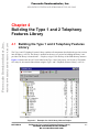
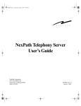
Figure 4-1 shows how the cid12.lib is linked to the Type 1 and 2 test project, cid12test.mcp. The header
file, teldefs.h, also must be linked when using the Type 1 and 2 Telephony Features Library, cid12.lib.
.
Figure 4-1. Example of a cid12 Library Link to a Project
MOTOROLA
Building the Type 1 and 2 Telephony Features Library
For More Information On This Product,
Go to: www.freescale.com
4-1
Freescale Semiconductor, Inc.
Building the Type 1 and 2 Telephony Features Library
ARCHIVED BY FREESCALE SEMICONDUCTOR, INC. 2005
Freescale Semiconductor, Inc...
ARCHIVED BY FREESCALE SEMICONDUCTOR, INC. 2005
4-2
Type 1 and 2 Telephony Features Library
For More Information On This Product,
Go to: www.freescale.com
MOTOROLA
Freescale Semiconductor, Inc.
ARCHIVED BY FREESCALE SEMICONDUCTOR, INC. 2005
ARCHIVED BY FREESCALE SEMICONDUCTOR, INC. 2005
Freescale Semiconductor, Inc...
Chapter 5
Linking Applications with the Type 1
and 2 Telephony Features Library
5.1 Type 1 and 2 Telephony Features Library
The Type 1 and 2 Telephony Features Library consists of an initialization and processing function. The
Type 1 and 2 Telephony Features Library can be initialized and created by the Type12CIDinit and
Type12CIDcreate functions. Their functionality and arguments are described in Section 3.3.3 and
Section 3.3.1, respectively. The library contains APIs, which provide the interface between the user
application and the Type 1 and 2 Telephony Features Library. To use the Type 1 and 2 Telephony Features
Library, APIs must be called in the following order:
—
—
—
—
Type12CIDcreate(....);
Type12CIDdestroy(....);
Type12CIDinit(….);
Type12CID(….);
//The user must call this function once for every instance
//The user must call this function to deallocate memory
//The user must call this function for hook switch change
//The user must call this function to display Caller ID in on-hook
and off-hook states
5.1.1 Library Sections
An example of the memory section for the Type 1 and 2 Telephony Features Library is shown in this
section. The data memory requirement for the Type 1 and 2 Telephony Features Library is 127 words. The
size of the program space requires 1.2Kwords. All program and data memory may reside in internal or
external memory. A dynamic memory section of at least 127 words, plus 16 words aligned on a 16-word
boundary, is required. All program memory for this library resides in section cid12.text of the code. An
example linker.cmd file is shown in Code Example 5-1.
The program and data memory for the Type 1 and 2 Telephony Features Library are in the FSK section of
the code. This text and data section contains all the code and data necessary to execute the Type12CID
function.
MOTOROLA Linking Applications with the Type 1 and 2 Telephony Features Library
For More Information On This Product,
Go to: www.freescale.com
5-1
Freescale Semiconductor, Inc.
Linking Applications with the Type 1 and 2 Telephony Features Library
ARCHIVED BY FREESCALE SEMICONDUCTOR, INC. 2005
Code Example 5-1. Example of a linker.cmd File for Type 1 and 2 Telephony Features Library
#*******************************************************************************
#
# Linker.cmd file for DSP56858 External RAM
# using only external program and data memory.
#
#*******************************************************************************
ARCHIVED BY FREESCALE SEMICONDUCTOR, INC. 2005
Freescale Semiconductor, Inc...
MEMORY {
.pInterruptVector
.pIntRAM
.pExtRAM
.pIntROM
.xIntRAM
.xIntRAM_DynamicMem
.xStack
.xExtRAM_DynamicMem
.xExtRAM
.xPeripherals
.xExtRAM2
.xCoreRegisters
(RWX)
(RWX)
(RWX)
(RX)
(RW)
(RW)
(RW)
(RW)
(RW)
(RW)
(RW)
(RW)
:
:
:
:
:
:
:
:
:
:
:
:
ORIGIN
ORIGIN
ORIGIN
ORIGIN
ORIGIN
ORIGIN
ORIGIN
ORIGIN
ORIGIN
ORIGIN
ORIGIN
ORIGIN
=
=
=
=
=
=
=
=
=
=
=
=
0x000000,
0x00008C,
0x00A000,
0x1F0000,
0x000000,
0x005000,
0x006000,
0x006800,
0x000000,
0x1FFC00,
0x200000,
0xFFFF00,
LENGTH
LENGTH
LENGTH
LENGTH
LENGTH
LENGTH
LENGTH
LENGTH
LENGTH
LENGTH
LENGTH
LENGTH
=
=
=
=
=
=
=
=
=
=
=
=
0x00008C
0x009F74
0x1E6000
0x000400
0x005000
0x001000
0x000800
0x001000
0x005000
0x000400
0xDFFF00
0x000100
}
#*******************************************************************************
FORCE_ACTIVE {FconfigInterruptVector}
#*******************************************************************************
SECTIONS {
#*******************************************************************************
.ApplicationInterruptVector :
{
vector.c (.text)
} > .pInterruptVector
#*******************************************************************************
.ApplicationCode :
{
# Place all code into Program RAM
*
*
*
*
(.text)
(rtlib.text)
(fp_engine.text)
(user.text)
# Place all data into Program RAM
F_Pdata_start_addr_in_ROM = 0;
F_Pdata_start_addr_in_RAM = .;
5-2
Type 1 and 2 Telephony Features Library
For More Information On This Product,
Go to: www.freescale.com
MOTOROLA
Freescale Semiconductor,
Inc.
Type 1 and 2 Telephony Features Library
ARCHIVED BY FREESCALE SEMICONDUCTOR, INC. 2005
pramdata.c (.data)
F_Pdata_ROMtoRAM_length = 0;
F_Pbss_start_addr = .;
_P_BSS_ADDR = .;
pramdata.c (.bss)
F_Pbss_length = . - _P_BSS_ADDR;
} > .pExtRAM
ARCHIVED BY FREESCALE SEMICONDUCTOR, INC. 2005
Freescale Semiconductor, Inc...
#****************************************************************************
.CID12LibrayCode :
{
# Place cid12 code into Program Internal RAM
* (cid12.text)
} > .pIntRAM
****************************************************************************
.ApplicationData :
{
# Define variables for C initialization code
F_Xdata_start_addr_in_ROM
F_StackAddr
F_StackEndAddr
F_Xdata_start_addr_in_RAM
=
=
=
=
.;
ADDR(.xStack);
ADDR(.xStack) + SIZEOF(.xStack) - 1;
.;
# Define variables for SDK mem library
# Data (X) Memory Layout
_EX_BIT
= 0;
# Internal Memory Partitions (for mem.h partitions)
_NUM_IM_PARTITIONS = 0;
# IM_ADDR_1 (no IM_ADDR_2 )
# External Memory Partition (for mem.h partitions)
_NUM_EM_PARTITIONS = 1;
# EM_ADDR_1
FmemEXbit = .;
WRITEH(_EX_BIT);
FmemNumIMpartitions = .;
WRITEH(_NUM_IM_PARTITIONS);
FmemNumEMpartitions = .;
WRITEH(_NUM_EM_PARTITIONS);
FmemIMpartitionList = .;
MOTOROLA Linking Applications with the Type 1 and 2 Telephony Features Library
For More Information On This Product,
Go to: www.freescale.com
5-3
Freescale Semiconductor, Inc.
Linking Applications with the Type 1 and 2 Telephony Features Library
ARCHIVED BY FREESCALE SEMICONDUCTOR, INC. 2005
WRITEH(ADDR(.xIntRAM_DynamicMem)*1);
WRITEH(SIZEOF(.xIntRAM_DynamicMem)*1);
FmemEMpartitionList = .;
WRITEH(ADDR(.xExtRAM_DynamicMem)*1);
WRITEH(SIZEOF(.xExtRAM_DynamicMem)*1);
# Add rest of the data into External RAM
*
*
*
*
(.const.data)
(.data)
(fp_state.data)
(rtlib.data)
F_Xbss_start_addr = .;
_X_BSS_ADDR = .;
ARCHIVED BY FREESCALE SEMICONDUCTOR, INC. 2005
Freescale Semiconductor, Inc...
F_Xdata_ROMtoRAM_length = 0;
* (rtlib.bss.lo)
* (rtlib.bss)
* (.bss)
F_Xbss_length = . - _X_BSS_ADDR;
# Copy DATA
} > .xExtRAM
#****************************************************************************
FArchIO
FArchCore
FArchInterrupts
= 0x0000;
= ADDR(.xCoreRegisters);
= ADDR(.pInterruptVector);
}
5-4
Type 1 and 2 Telephony Features Library
For More Information On This Product,
Go to: www.freescale.com
MOTOROLA
Freescale Semiconductor, Inc.
ARCHIVED BY FREESCALE SEMICONDUCTOR, INC. 2005
ARCHIVED BY FREESCALE SEMICONDUCTOR, INC. 2005
Freescale Semiconductor, Inc...
Chapter 6
Type 1 and 2 Telephony Features
Library Applications
6.1 Type 2 Verification Test
To verify the functionality of the Type 1 and 2 Telephony Features Library, an individual test application
is provided. The test processes the samples that are precaptured from a nominal FSK transmission. The
corresponding Caller ID will be printed on screen. The test application is located in the
...telephony\cidtype12\Test directory. The name of the test project is cid12test.mcp.
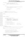
6.1.1 Test Set-up and Procedure
The test application runs in the simulator mode and does not require external equipment. Before executing
the test application, select Simulator as the Target Setting Protocol. It can be set in the Protocol option of
the M56800 Target Settings.
The test project for Type 2 is cid12test.mcp. Before loading the executable project, the project must be
compiled with no errors. This is done by choosing the Make option in the Project menu, or by pressing
[F7]. To load the executable project, choose the Debug option in the Project menu, or press [F5].
To run the test application, use the mouse to click the green arrow button or manually press [F5] on the
keyboard. After the application starts running, the application initializes and automatically processes the
precaptured samples.
The functionality of the Type 1 and 2 Telephony Features Library will be verified, and a Caller ID message
will be printed on the console window. The application stops after completing the process and prints
“PASS” on the console window.
Should the application print “FAIL”, the Type 1 and 2 Telephony Features Library is not operating
correctly. This is not expected to happen for this test application; however, if it does, please report the
failure and test conditions to Motorola for resolution.
MOTOROLA
Type 1 and 2 Telephony Features Library Applications
For More Information On This Product,
Go to: www.freescale.com
6-1
Freescale Semiconductor, Inc.
Type 1 and 2 Telephony Features Library Applications
ARCHIVED BY FREESCALE SEMICONDUCTOR, INC. 2005
6.2 Example Application Using cid12.lib
An example using the Type 1 and 2 Telephony Features Library to illustrate how to set the library
variables for Type12CID in the Control structure of teldefs.h is shown in Code Example 6-1. This code
does not exist in the actual cidtype12 directory in the SDK.
ARCHIVED BY FREESCALE SEMICONDUCTOR, INC. 2005
Freescale Semiconductor, Inc...
Code Example 6-1. Use of Type12CID Interface
#include <stdio.h>
#include <stdlib.h>
#include "teldefs.h"
#include "cid12.h"
#include "mem.h"
#ifdef USEPARSER
#include "cidparser.h"
#endif
#ifdef USEGEC
#include "gec.h"
#endif
struct teldefs_tsSamples Line1Samples;
struct cid_tsData* pcid1Data;
struct teldefs_tsControl Line1Control;
#ifdef USEPARSER
teldefs_sParser ParserControl;
#endif
#ifdef USEGEC
struct gec_tsData* pgec1Data;
#endif
int main(void)
{
// Initialize some necessary structure elements and call create function
Line1Control.messageDone=0;
Line1Control.cidByteReady = 0;
Line1Control.ExtUseCheck=0;
Line1Control.NoExtFound=1;
Line1Control.FrameErrors=0;
Line1Control.dtmfRequest=0;
Line1Control.dtmfComplete=0;
Line1Control.hookSwitch = 0;
Line1Control.flashCommand = 0;
Line1Control.cwdCommand = 0;
pcid1Data = Type12CIDcreate(&Line1Control);
#ifdef USEPARSER
ParserControl.FskMessageIndex=0;
ParserControl.FskParserLength=0;
#endif
6-2
Type 1 and 2 Telephony Features Library
For More Information On This Product,
Go to: www.freescale.com
MOTOROLA
Freescale Semiconductor,
Inc.
Example Application Using cid12.lib
ARCHIVED BY FREESCALE SEMICONDUCTOR, INC. 2005
#ifdef USEGEC
//initialize all process variables for GEC
Line1Control.gecLengthIndex = 0;
pgec1Data = gecEchoCancellerCreate(&Line1Control);
#endif
while(1) {
/* Wait for 5 8KHz samples to be received and transmitted by */
/* the Codec Interrupt Service Routine. */
while(!SamplesReady){
;
}
CalleridAppMain();
/* do nothing */
ARCHIVED BY FREESCALE SEMICONDUCTOR, INC. 2005
Freescale Semiconductor, Inc...
}
Type12CIDdestroy(pcid1Data,&Line1Control);
#ifdef USEGEC
gecEchoCancellerDestroy(pgec1Data, &Line1Control);
#endif
return 0;
}
void CalleridAppMain(){
int i;
/* copy samples from Codec buffers */
for( i = 0; i < 5 ; i++){
codecBufferLeftout[i] = Line1Samples.audio[i];
codecBufferRightout[i] = Line1Samples.line[i];
Line1Samples.line[i] = codecBufferLeftin[i];
Line1Samples.audio[i] = codecBufferRightin[i];
}
// Get Ring Signal from DAA
if( /* Poll Ring Detect Bit Here */ ){
Line1Control.cidRingPolarity = 1;
}
else{
Line1Control.cidRingPolarity = 0;
}
// Ring present
// Ring not present
#ifdef USEGEC
// Call Generic Echo Canceller
for(i=0;i<5;i++) gecEchoCanceller(pgec1Data,&Line1Control,&Line1Samples);
#else
for(i=0;i<5;i++) Line1Samples.leccid[i] = Line1Samples.line[i];
#endif
// Call Type 1 and 2 Telephony Features Library
Type12CID(pcid1Data,&Line1Control,&Line1Samples);
// Do extension in use check. If no detection circuit is
// present, always set Line1Control.NoExtFound = 1
if(Line1Control.ExtUseCheck == 1){
MOTOROLA
Type 1 and 2 Telephony Features Library Applications
For More Information On This Product,
Go to: www.freescale.com
6-3
Freescale Semiconductor, Inc.
Type 1 and 2 Telephony Features Library Applications
ARCHIVED BY FREESCALE SEMICONDUCTOR, INC. 2005
// Go onhook
go_onhook();
// Process command for line flash
ARCHIVED BY FREESCALE SEMICONDUCTOR, INC. 2005
Freescale Semiconductor, Inc...
}
else if(Line1Control.ExtUseCheck == 2){
// Detect extension in use here.
if( /* poll extension in use check here */ ){
Line1Control.NoExtFound = 0;
}
else{
Line1Control.NoExtFound = 1;
}
}
else if(Line1Control.ExtUseCheck == 3){
// Go offhook
go_offhook();
Line1Control.ExtUseCheck=0;
}
if(Line1Control.flashCommand){
Line1Control.flashCommand = 0;
if(Line1Control.flashPolarity == 1) go_offhook();
else go_onhook();
}
#ifdef USEPARSER
// Use Type 1 and 2 Telephony Parser Library
CIDMessageParser(&ParserControl, &Line1Control);
if(ParserControl.FskParserLength != 0){
/* Parsed Message Ready. Send to Output Device */
if(ParserControl.ErrorType == 0){
for( i = 0 ; i < ParserControl.FskParserLength ; i++)
printf("%c",ParserControl.FskParserBuffer[i]);
}
ParserControl.FskParserLength=0;
}
#elseif
// Use Custom Parser
if(Line1Control.cidByteReady){
/* Buffer cid bytes here*/
cid_message_buffer[cid_message_index++] = Line1Control.cidByte;
}
if (Line1Control.messageDone){
if(Line1Control.FrameErrors == 0){
/* Call custom Parser here */
}
else Line1Control.FrameErrors = 0;
}
#endif
}
6-4
Type 1 and 2 Telephony Features Library
For More Information On This Product,
Go to: www.freescale.com
MOTOROLA
Freescale Semiconductor,
Inc.
Example Application Using cid12.lib
ARCHIVED BY FREESCALE SEMICONDUCTOR, INC. 2005
Code Example 6-1 shows a basic application using the cid12.lib module. This module is designed to
interact with the Type 1 and 2 Telephony Parser Library (cidparser.lib); however, independent use of the
cid12.lib module is supported. When receiving Type 2 Caller ID, it is recommended that an echo canceller
be incorporated to attenuate network echo, most easily accomplished by using the gec.lib module. When
implementing a full duplex speakerphone, the cid12.lib module is intended to be used with the fdspk.lib
and gec.lib modules; however, custom line echo canceller and full duplex speakerphone software can also
interface with the cid12.lib module.
ARCHIVED BY FREESCALE SEMICONDUCTOR, INC. 2005
Freescale Semiconductor, Inc...
This example shows how to manage Caller ID information using either the Type 1 and 2 Telephony Parser
Library or a custom parser. When a custom parser is desired, the definition USEPARSER is undefined.
When using a custom parser, the application must transfer the input bytes into a buffer, then process them.
This is done automatically when using the Type 1 and 2 Telephony Parser Library.
While this module is primarily intended to be used for Caller ID reception, other convenient features are
added to allow for simple integration into a Caller ID telephone. While the module is in an on-hook state
(Line1Control.hookSwitch = 0), the line[] samples buffer will be filled with ring generator samples during
power ringing. Otherwise, the line[] samples will be filled with zeros. These samples may act as an output
to an audio channel (for example, to be played to a speaker).
While the module is in an off-hook state (Line1Control.hookSwitch = 1), the audio[] samples buffer will
be overwritten with DTMF samples when a DTMF digit is requested for dialing, or to acknowledge the
reception of a CAS tone, and will remain unchanged otherwise. The line[] samples remain unchanged
during the off-hook state, unless Line1Control.handsFreeLayer1 is set (a condition which is not shown in
this example). In this case, the gec[] samples will be copied to the line[] samples structure. In addition,
during off-hook FSK reception, both the line[] and audio[] samples will be muted (set equal to zero),
regardless of the value of Line1Control.handsFreeLayer1.This is required since no signal should be
transmitted by the CPE onto the telephone line or played on the speaker during data reception, as specified
by the CIDCW standard.
The gec[] samples can be obtained by using the gec.lib module, or by using a separate custom echo
canceller. The audio[] samples will be modified by the fdspk.lib module (or custom full duplex
speakerphone software) in this case.
The input samples to the Type 1 and 2 Telephony Features Library CAS detector are taken from the
leccid[] sample buffer. When using gec.lib, this buffer will be filled automatically with echo cancelled line
samples. If no echo canceller is used, copy the five samples from the line[] buffer into the leccid[] buffer
prior to calling Type12CID().
The Type 1 and 2 Telephony Features Library supports all necessary timing and logic needed for the
application to easily check if an extension phone is off-hook following reception of a CAS tone, as
specified in SR-3004. Upon reception of a CAS tone, if an extension phone is found to be off-hook, the
Type 1 and 2 Telephony Features Library will not send back a DTMF acknowledgement; therefore, no
FSK Caller ID signal will be sent. By simply monitoring ExtUseCheck, the application will know when to
go on-hook, when to monitor line voltage to determine if an extension is found and set NoExtFound
accordingly, and when to go back off-hook. For more information regarding monitoring line voltage to
determine if an extension is off-hook, see SR-3004. When taking the phone on-hook or off-hook as a result
of a ExtUseCheck command, the application should not change the Line1Control.hookSwitch variable or
call Type12CIDinit().
MOTOROLA
Type 1 and 2 Telephony Features Library Applications
For More Information On This Product,
Go to: www.freescale.com
6-5
Freescale Semiconductor, Inc.
Type 1 and 2 Telephony Features Library Applications
ARCHIVED BY FREESCALE SEMICONDUCTOR, INC. 2005
In this example, there are two GPIO pins: one output pin, which places the telephone interface on-hook or
off-hook, and one input pin, which indicates the ring detect from the telephone interface. The ring detect
pin is polled in the application and its polarity is placed in the variable Line1Control.cidRingPolarity. This
information is necessary for the Type 1 and 2 Telephony Features Library, even when disableRinger is set
(disabling the ring tone generator) and should be polled at a rate of 1600/sec as shown in the application.
However, slower polling rates may be tolerated.
ARCHIVED BY FREESCALE SEMICONDUCTOR, INC. 2005
Freescale Semiconductor, Inc...
It is assumed that the functions go_onhook() and go_offhook(), which are not shown in Code
Example 6-1, would simply set or clear the output pin connected to the telephone interface. However, note
that these are not the same as when the application actually puts the module into an on-hook or off-hook
state. In this situation, the application must also set or clear the Line1Control.hookSwitch variable , then
call Type12CIDinit().
The Codec Interrupt Service Routine is also not shown in this example. This routine is assumed to transmit
and receive 8KHz samples from a codec and read/write to the buffers codecBufferLeftin[] and
codecBufferLeftout[]. This codec is connected to the telephone line interface. This routine is also assumed
to transmit and receive 8KHz samples from a codec and to read/write to the buffers codecBufferRightin[]
and codecBufferRightout[]. This codec is connected to an audio interface. When the ISR has
received/transmitted five samples, the buffers are full/empty, and the SamplesReady flag is set, indicating
to the application that it should call CalleridAppMain(). The calling rate of this routine should be 1600
calls/second.
In the beginning of the CalleridAppMain() routine, the codec samples are copied into the module’s sample
structure. Note that for the output samples, the line[] samples are copied into the right (audio) codec
channel, and the audio[] samples are copied into the left (line) codec channel. This sample "criss-cross" is
indicative of the natural signal flow for a telephone.
6-6
Type 1 and 2 Telephony Features Library
For More Information On This Product,
Go to: www.freescale.com
MOTOROLA
Freescale Semiconductor, Inc.
ARCHIVED BY FREESCALE SEMICONDUCTOR, INC. 2005
7.1 Limited Use License Agreement
ARCHIVED BY FREESCALE SEMICONDUCTOR, INC. 2005
Freescale Semiconductor, Inc...
Chapter 7
License
This software is available under a separate license agreement from Motorola Incorporated.
Licensing information can be obtained from your Motorola sales representative or authorized
distributor.
For additional product information, see http://www.motorola.com/semiconductors/.
MOTOROLA
License
For More Information On This Product,
Go to: www.freescale.com
7-1
License
Freescale Semiconductor, Inc.
ARCHIVED BY FREESCALE SEMICONDUCTOR, INC. 2005
Freescale Semiconductor, Inc...
ARCHIVED BY FREESCALE SEMICONDUCTOR, INC. 2005
7-2
Type 1 and 2 Telephony Features Library
For More Information On This Product,
Go to: www.freescale.com
MOTOROLA
Freescale Semiconductor, Inc.
ARCHIVED BY FREESCALE SEMICONDUCTOR, INC. 2005
Index
ARCHIVED BY FREESCALE SEMICONDUCTOR, INC. 2005
Freescale Semiconductor, Inc...
A
ACK x, 1-7
Acknowledgement signal
ACK x, 1-7
ADC xi, 1-4, 1-5
AGC xi
American Standard Code for Information Interchange
ASCII xi, 3-1
Analog-to-Digital Converter
ADC xi, 1-4, 1-5
API xi, 5-1
appconfig.c 2-3
appconfig.h 2-3
Application Programming Interface
API xi, 5-1
ASCII xi, 3-1
Attenuation Distortion 1-4
Automatic Gain Control
AGC xi
B
Bandpass Filter
BPF xi
BPF xi
C
C Q xi
Call Qualifier
CQ xi, 1-2
Call Waiting Deluxe 1-6, 3-5
CWD xi
Call Waiting Tone 1-7
Call Waiting with Call Disposition 1-6
Caller ID 1-2
CID xi
Calling Identity Delivery on Call Waiting
CIDCW xi, 1-6
Calling Name Delivery 1-2
Calling Number Delivery 1-2
call-terminating switching system 1-7
CAS xi, 1-6
CAS Detector 1-8
Central Office
CO xi, 1-7
CID xi
cid12.h 3-3
cid12.lib 2-3, 4-1, 6-2
MOTOROLA
cid12test.mcp 2-3, 4-1, 6-1
CIDCW xi, 1-6
CO xi, 1-7
CPE xi, 1-2
CPE Alerting Signal
CAS 1-6
CQ 1-2
Customer Premises Equipment
CPE xi, 1-2
Customer premises equipment Alerting Signal
CAS xi
CWD xi
D
DAA xi, 1-3
Data Access Arrangement
DAA xi, 1-3
Digital Signal Processor
DSP xi, 1-1
DSP xi, 1-1
DSP56800E Reference Manual xi
DSP56858EVM 2-1
DSP56858EVM board 1-4
DSP5685x User’s Manual xi
DTMF xi, 1-7, 3-1
Dual Tone Multiple Frequency
DTMF xi, 1-7, 3-1
E
Embedded SDK Programmer’s Guide xi
F
Frequency Response 1-3
Frequency Shift Keying
FSK xi, 1-3, 1-6
FSK xi, 1-3, 1-6
G
G.726 2-2
GR-1188-CORE, LSSGR CLASS Feature
Calling Name Delivery Generic Requirements xii
GR-1401-CORE, LSSGR CLASS Feature
Visual Message Waiting Indicator Generic
Requirements xii
GR-30-CORE 1-2
GR-30-CORE, LSSGR
Voiceband Data Transmission Interface xii
Index
For More Information On This Product,
Go to: www.freescale.com
i
Freescale Semiconductor, Inc.
ARCHIVED BY FREESCALE SEMICONDUCTOR, INC. 2005
GR-31-CORE, LSSGR CLASS Feature
Calling Number Delivery xii
GR-416-CORE, CLASS Feature Call Waiting
Deluxe xii
GR-575-CORE, LSSGR CLASS Feature Calling
Identity Delivery on Call Waiting xii
I
IDE xi
Integrated Development Environment
IDE xi
ITU-T Recommendation V.23 xii, 1-3
ARCHIVED BY FREESCALE SEMICONDUCTOR, INC. 2005
Freescale Semiconductor, Inc...
L
LEC xi, 1-8
Line Echo Canceller
LEC xi, 1-8
linker.cmd 2-3, 5-2
Low Pass Filter
LPF xi
LPF xi
S
SAS 1-6, 1-7
SDK xi, 1-1
SDMF xi, 1-2
Sensitivity 1-6
Single Data Message Format
SDMF xi, 1-2
Software Development Kit
SDK xi, 1-1
Source
SRC xi
SR-3004, Testing Guidelines for Analog Type 1, 2, and
3 CPE xi
SRC xi
Subscriber Alerting Signal
SAS 1-6, 1-7
T
M
MDMF xi, 1-2
Memory and MIPS Requirements 1-8
Million Instructions Per Second
MIPS xi
MIPS xi
Multiple Data Message Format
MDMF xi, 1-2
O
off-hook Caller ID 1-2
OnCE xi
On-Chip Emulation
OnCE xi
on-hook Caller ID 1-2
Open Switching Intervals
OSI 1-3
OSI 1-3
Targeting Motorola DSP5685x Platform xi
Telcordia SR-3004 1-2, 3-1
teldefs.h 3-1, 4-1, 6-2
Twist 1-3, 1-6
Type 1 and 2 Telephony Features Library 1-1, 1-6
Type 1 and 2 Test Project 4-1
Type 1 services 1-2
Type 12 Module 1-6
Type 2 CPE 1-6
Type 2 services 1-2
Type12CID 5-1, 6-2
Type12CID Module 1-6
Type12CID.lib 3-1
Type12CIDcreate 5-1
Type12CIDdestroy 5-1
Type12CIDinit 5-1
V
Visual Message Waiting Indicator
VMWI xi, 1-2, 3-1
VMWI xi, 1-2, 3-1
Voiceband Data Transmission Interface 1-2
P
PC xi
PCM xi
Personal Computer
PC xi
PSTN xi, 1-2, 1-7
Public Switched Telephone Network
PSTN xi, 1-2, 1-7
Pulse Code Modulation
PCM xi
ii
Type 1 and 2 Telephony Features Library
For More Information On This Product,
Go to: www.freescale.com
MOTOROLA
Freescale Semiconductor, Inc.
ARCHIVED BY FREESCALE SEMICONDUCTOR, INC. 2005
Freescale Semiconductor, Inc...
ARCHIVED BY FREESCALE SEMICONDUCTOR, INC. 2005
For More Information On This Product,
Go to: www.freescale.com
Freescale Semiconductor, Inc.
ARCHIVED BY FREESCALE SEMICONDUCTOR, INC. 2005
Freescale Semiconductor, Inc...
ARCHIVED BY FREESCALE SEMICONDUCTOR, INC. 2005
Motorola reserves the right to make changes without further notice to any products herein. Motorola makes no warranty, representation or guarantee regarding the
suitability of its products for any particular purpose, nor does Motorola assume any liability arising out of the application or use of any product or circuit, and
specifically disclaims any and all liability, including without limitation consequential or incidental damages. “Typical” parameters which may be provided in Motorola
data sheets and/or specifications can and do vary in different applications and actual performance may vary over time. All operating parameters, including
“Typicals” must be validated for each customer application by customer’s technical experts. Motorola does not convey any license under its patent rights nor the
rights of others. Motorola products are not designed, intended, or authorized for use as components in systems intended for surgical implant into the body, or other
applications intended to support or sustain life, or for any other application in which the failure of the Motorola product could create a situation where personal injury
or death may occur. Should Buyer purchase or use Motorola products for any such unintended or unauthorized application, Buyer shall indemnify and hold Motorola
and its officers, employees, subsidiaries, affiliates, and distributors harmless against all claims, costs, damages, and expenses, and reasonable attorney fees
arising out of, directly or indirectly, any claim of personal injury or death associated with such unintended or unauthorized use, even if such claim alleges that
Motorola was negligent regarding the design or manufacture of the part. Motorola and the Stylized M Logo are registered trademarks of Motorola, Inc. Motorola,
Inc. is an Equal Opportunity/Affirmative Action Employer.
MOTOROLA and the Stylized M Logo are registered in the US Patent & Trademark Office. All other product or service names are the property of their
respective owners. © Motorola, Inc. 2002.
How to reach us:
USA/EUROPE/Locations Not Listed: Motorola Literature Distribution; P.O. Box 5405, Denver, Colorado 80217. 1–303–675–2140 or 1–800–441–2447
JAPAN: Motorola Japan Ltd.; SPS, Technical Information Center, 3–20–1, Minami–Azabu. Minato–ku, Tokyo 106–8573 Japan. 81–3–3440–3569
ASIA/PACIFIC: Motorola Semiconductors H.K. Ltd.; Silicon Harbour Centre, 2 Dai King Street, Tai Po Industrial Estate, Tai Po, N.T., Hong Kong. 852–26668334
Technical Information Center: 1–800–521–6274
HOME PAGE: http://www.motorola.com/semiconductors/
For More Information On This Product,
Go to: www.freescale.com
SDK140/D