1
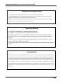
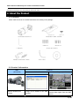
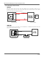
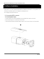
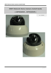
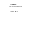
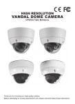
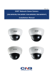
XNET Network Weatherproof Camera Installation Guide XNET Network Weatherproof Camera (IXC2050IR) Installation Guide Ver. 1.0 1/20 XNET Network Weatherproof Camera Installation Guide About this Installation Guide A compatibility and durability test ensured this product’s high performance. This installation guide is for XNET Network Weatherproof Camera users only, and it describes operations related to XNET Network Weatherproof Camera. Please read this manual thoroughly paying attention to cautions and warnings before using the product even if you have used similar products before. Important Notices The copyright of this manual is owned by CNB Technology Inc. It is illegal to copy and distribute this manual without permission. Damages caused by use of not suggested parts and misuse will not be applicable for support. Contact the store or the manufacturer immediately if (you think) there is any problem with the product. Contact the store or the manufacturer before disassembling the product for alteration or repair. XNET is a trademark of CNB Technology Inc. This product complies for CE (Europe) and FCC (USA) regulations for industrial/home use electrical device. INFORMATION This equipment has been tested and found to comply with the limits for a Class A digital device, pursuant to Part 15 of the FCC Rules. These limits are designed to provide reasonable protection against harmful interference when the equipment is operated in a commercial environment. This equipment generates, uses and can radiate radio frequency energy and, if not installed and used in accordance with the instruction manual, may cause harmful interference to radio communications. Operation of this equipment in a residential area is likely to cause harmful interference in which case the user will be required to correct the interference at his own expense. 2/20 XNET Network Weatherproof Camera Installation Guide Index 1.About XNET ............................................................................................................................. 4 1.1. About XNET..................................................................................................................... 4 1.2. Features of XNET............................................................................................................. 4 1.3. Applications ..................................................................................................................... 4 2. About the Product ................................................................................................................... 5 2.1 Contents .......................................................................................................................... 5 2.2 Product Information .......................................................................................................... 5 2.3 Hardware ......................................................................................................................... 6 2.3.1 Hardware Designation ...........................................................................................6 2.3.2 Camera Module – Bottom ......................................................................................7 2.3.3 Cable Connection ..................................................................................................8 2.3.4 Connecting to Alarm Devices ..................................................................................9 3. Software Installation ............................................................................................................. 10 3.1. Connecting XNET to network .......................................................................................... 10 3.1.1. Mounting the Camera ......................................................................................... 15 3.1.2. Installing XNET .................................................................................................. 15 3.2. Installing IP-Installer Software and Configuring IP address .............................................. 15 3.2.1. About IP-Installer ............................................................................................... 15 3.2.2. IP Address Configuration .................................................................................... 15 4. Using Web Viewer ................................................................................................................. 17 4.1. Logging In .................................................................................................................... 17 4.2. Web Viewer Page........................................................................................................... 18 5. Specifications ....................................................................................................................... 19 3/20 XNET Network Weatherproof Camera Installation Guide 1.About XNET 1.1. About XNET XNET is an internet based security and surveillance system that is compatible with various network conditions through easy installation and user interface as well as multi-functional compressor Codec such as H.264, MJPEG. XNET provides stable real-time surveillance by real time video/ audio at 1080P level, local storage for any network problems, and hybrid IP technology that can be used with existing analog CCTV devices. 1.2. Features of XNET Progressive technology Progressive scan produces a sharp and clear image on moving objects, preventing a ghost effect. Hybrid IP Technology Analog video output can be used for any previously established analog CCTV systems. Multi-CoDec streaming Live video streaming can be done using MJPEG or MPEG-4(or H.264) to meet various network requirements. Smart Event feature In addition to motion detection and sensor/alarm feature, pre- and post- alarm feature allows fully automated surveillance without an operator. Install/ Operation Wizard Install/ Operation Wizard makes it easy to install and run the system, and it also offers a unified setup configuration for large and multiple installation projects. Up to 3 motion detection areas Motion Detection – Alarm output and Video/ Audio transmission to an FTP site by e-mail Various resolutions - 1080P(1920X1080),SXGA(1280X1024),SXGA(1280x960),720P(1280X720),D1(720X480), VGA(640x480),CIF(352x240) Control over the network for firmware upgrade and menu settings 1.3. Applications Surveillance (Building, store, factory, parking lot, financial institutions, government buildings, military facilities, etc.) Remote video monitoring (Hospital, kindergarten, traffic monitoring, remote branch office, weather, environment preservation, and illegal disposal of trash, etc.) Real time broadcasting over the internet (Resort facility, parties, festivals, etc), business meetings, 4/20 XNET Network Weatherproof Camera Installation Guide educational trainings over the network, and much more. 2. About the Product 2.1 Contents Please make sure that no contents listed below are missing in the package. SUNSHEILD AND SCREW IXC2050IR PRODUCT L Wrench Screw and Anchor Adaptor and Power Cable CD Video Cable 2.2 Product Information XNET (IXC2050IR) Network Weatherproof Camera Install CD IP-Installer assigns an IP address to the XNET product Viewer Program (XNET-NVR) A PC software that monitors and records Video signal from the XNET device 5/20 XNET Network Weatherproof Camera Installation Guide 2.3 Hardware 2.3.1 Hardware Designation Complete System ① MegaPixel Fixed Lens ② IR Illuminator : automatically illuminates depending on the light intensity ③ CDS Sensor ④ Screws (front-4EA & rear-4EA) : Sets the front and back cap ⑤ Sunsheild ⑥ Sunsheild fixing Screw : fixes the Sunsheild of the camera ⑦ Rotate adjusting Bolt : fixes the rotate angle of the camera ⑧ Tilt adjusting Screw : fixes the tilt angle of the camera ⑨ Pan adjusting Screw : fixes the pan angle of the camera ⑩ FRONT BODY ⑪ GASKET(Micro SD Card Slot, Video Out, Factory Reset Button) ⑫ CAMERA MODULE – BOTTOM ⑬ REAR-BODY 6/20 XNET Network Weatherproof Camera Installation Guide 2.3.2 Camera Module – Bottom ① Micro SD Card Slot : Enables recording of video data to an external memory device upon occurrence of an event. Please use less than 16 GB SD Memory. ② Video Out : Use this output to monitor the analog video signal while installing. (Select Video Out at menu screen to enable this output) ③ Factory Reset Button : Press and hold for more than 3 seconds while power is on to recall factory default settings ④ Power LED : Lights up Red when 12V DC power is connected. ⑤ ACT LED : Lights up Green when the XNET is connected to 100Mbps LAN. Will not light up at 10Mbps LAN. This will also blink green when there is a network collision. ⑥ Link LED : Lights up Yellow when the network is properly connected. 7/20 XNET Network Weatherproof Camera Installation Guide 2.3.3 Cable Connection Power Input Use the cable adapter in the package to connect power. Please use the accessory power supply provided in the package. (DC12V/2A) Analog Video Output Use this output for immediate monitoring of the video during installation. Use the supplied cable adapter (Yellow for video and Black for Video Ground GND) This adapter can be connected to a cable through a RCA termination. (Select Video Out at menu screen to enable this output) Alarm Connection These wires connect to Alarm input/output devices. Alarm Sensor Input: Connect to Alarm sensor devices such as IR Sensor or Heat sensor. These can be configured to normally close or normally open operation. (#3, #4) Alarm Output: Connect to Alarm devices such as Relay operated Siren Lamp or Alarm Light. These can be configured to normally close or normally open operation. (#1, #2) Please refer to “2.3.4 Connection to Alarm Devices” for detailed instruction on how to connect sensors and Relays. Do not use this connector when powering up the product through LAN cable(PoE). The product is not covered under warranty when it is damaged by connecting both Ethernet power and 12V DC power to this terminal. Network Cable This Ethernet terminal connects to 100Mbps LAN through an RJ-45 cable. When optional PoE is used, the power will be supplied from the Network Cable. Network cable of this product is not water proof 8/20 XNET Network Weatherproof Camera Installation Guide 2.3.4 Connecting to Alarm Devices Alarm Input Wires from various sensor type (IR, heat, and magnetic) can be connected to Alarm in(+)/(-) terminal as shown in figure 2.5. (NC or NO of sensor input can be selected at Menu screen.) Alarm Sensor device requires a separate power source. Internal Circuitry External Circuitry Alarm Output This terminal can only be connected up to DC 30V/400mA. An additional relay device has to be used to control higher voltage or current. Internal Circuitry External Circuitry 9/20 XNET Network Weatherproof Camera Installation Guide 3. Software Installation This section provides brief guidelines to install the XNET quickly and to monitor XNET’s Video and Audio signals easily. If you have questions about details not explained in this section or if the product is not functioning as described, please refer to FAQ before contacting the store. Our homepage is http://www.cnbtec.com. 3.1 Connecting XNET to network 3.1.1 Mounting the Camera A. Install Sunsheild to the Camera’s MAIN BODY using Sunsheild blocks, washers, and screws. B. Mount Bracket Support on a wall using four 6mm screws. C. Mount Wall mount Bracket on Bracket Support using four 5/16” screws as shown in the figure below: 10/20 XNET Network Weatherproof Camera Installation Guide 3.1.2 Installing XNET Connect XNET to PC directly User can monitor and configure XNET camera by connecting it to your PC directly. A. Connect XNET camera to your PC directly using a LAN cable like below. COMPUTER Crossover Network Cable NOTE: XNET camera’s IP address will be automatically set to the default value, 192.168.123.100, after connecting XNET camera to your PC directly. (This process approximately takes 20~30 seconds) B. Please follow the direction to modify PC’s network configuration. Windows Start Control Panel Network Connections Right-clicks on the Local Area Connection icon Double click on the Internet Protocol (TCP/IP) icon. Please set PC’s network configuration like below. NOTE: IP address for PC can be set from 192.168.123.2 to 192.168.123.254. Since XNET camera’s IP address is already set to 192.168.123.100, you cannot allocate this IP address to PC. 11/20 XNET Network Weatherproof Camera Installation Guide C. Please insert the Setup CD into your CD-ROM drive, and then please setup IPInstaller program D. Please click ‘Next’ button when the Setup screen appear. E. Please click ‘Install’ button to begin the Installation. F. Please click ‘Finish’ button to complete the installation. 12/20 XNET Network Weatherproof Camera Installation Guide G. XNET IP Installer program is automatically launched like below right after the program installation. Please double click XNET camera on the list. H. XNET camera is successfully connected to your PC. (Internet Explorer will prompt you to install ActiveX. In order to view video, you must accept the ActiveX download. ) NOTE: Please select Setting menu for XNET camera configuration. If the login prompt appears, please enter User name and Password. XNET camera’s Default User name and Password User name : root Password : admin 13/20 XNET Network Weatherproof Camera Installation Guide Connect XNET with a router Please connect XNET camera and PC to a router using LAN cables like below. COMPUTER Direct Network Cable NOTE : If DHCP server is enabled at your router, XNET camera automatically receives an IP address from your router. Otherwise, XNET camera’s IP address will be automatically set to the default value, 192.168.123.100. 14/20 XNET Network Weatherproof Camera Installation Guide 3.2. Installing IP-Installer Software and Configuring IP address 3.2.1. About IP-Installer A unique IP address has to be configured in order to connect IP camera and monitoring PC to a network. IP-Installer software provided in the Installation CD (included in the package and also available to download from our website http://www.cnbtec.com) will configure IP address easily. If your network have a DHCP server that automatically assigns IP addresses to IP cameras. If your network does not have a DHCP server, the default IP address of the device is 192.168.123.100. Refer to IP Installer user’s manual for detail. 3.2.2. IP Address Configuration A. The following window will pop up when you start the IP-installer software. Figure 3-1. IP Installer Window 15/20 XNET Network Weatherproof Camera Installation Guide B. Select the camera you wish to configure and click (Set IP Address) button to open the box shown in Figure 3-2. Figure 3-2. Set IP Address box C. When you enter the IP address and click Set button, the box shown in Figure 3-3 will appear. Figure 3-3. Select Network Adapter Box D. Select the adapter and click select button to change the IP address of the camera. 16/20 XNET Network Weatherproof Camera Installation Guide 4. Using Web Viewer Connecting to network devices can be done using internet web browser or “XNET-CMS” software. This guide explains about using internet web browser only. For instructions on how to configure network connection using XNET-CMS software, please refer to XNET-CMS Manual, which can be found in the installation CD. 4.1. Logging In Enter the IP address of the device on the address bar of your web browser and press enter key. Then the following webpage will appear: Figure 4-1. Log-in Box Enter the user name and password to bring up the web viewer page. The default id and password is “root”, “admin” respectively. If you want to use a different HTTP port number from the default value, simply put a colon and port number at the end of the IP address. (For example, enter the following address when changing the port to 8080: http://192.168.123.100:8080) <Address format for accessing as an administrator> (When using default IP address and port number) http://192.168.123.100 (When IP address and port number changed) http://IP address: new port number For security purpose, it is recommended to change the administrator’s id and password from their default values. Please be careful not to forget them or expose them to others. Please refer to [Web Viewer Manual] for detail. If you forget the administrator’s password, “Factory Reset” is the only way to regain access. However, since this will retrieve all default settings, you need to configure the network settings using IP installer software again. 17/20 XNET Network Weatherproof Camera Installation Guide 4.2. Web Viewer Page Web viewer page consists of Video monitor screen and menu option buttons. Figure 4-2 Web Viewer page Item Capture Sub Item - Description Captures and saves the current image as a still picture. The image is saved as jpeg file in the following folder: C:₩xNetCapture Brings up Menu screen. Setting - Setup page for each XNET feature can be opened from this Menu screen. Please refer to [XNET Owner’s Manual] for detail. Main Stream When this box is checked, Main Stream Video is displayed. When this box is checked, Sub Stream Video is displayed. Live View Sub Stream Dual-Codec needs to be enabled in Video Setup Page in order for Sub Stream to be displayed. Please refer to [XNET Owner’s Manual] for detail. 18/20 XNET Network Weatherproof Camera Installation Guide 5. Specifications IXC2050IR Signal System Specifications Progressive image processing Scanning System Camera 16:9 Progressive Pixel Clock 80MHz Image Sensor 1/3" Progressive CMOS Sensor Sync. System Internal Effective Pixels Number 1920 (H) x 1080(V) 2.0 Mega Horizontal Resolution 1100 TV Lines Video Output Level Select NTSC/PAL 1.0Vp-p (RCA 75Ω, composite) Lens Built-in Fixed Mega pixel Lens, f=4.0mm, F 2.0 Min. Illumination 1.00Lux (Color, DSS On), 0.00Lux (IR LED On) IR LED and Sensor 850nm / 45˚ IR LED 30EA, Sensor 1EA IR LED Lighting Distance MAX 25m Day & Night System ICR(CDS Type) Back Light Compensation On/Off Flickerless On/Off White Balance Auto/Manual Exposure Auto/Manual Functions Electronic Shutter Speed B/W NTSC : 1/7.5 ~ 1/8000 (21 Step) PAL : 1/7.5 ~ 1/8000 (21 Step) Compression Video / Audio Frame rate Resolution Protocol Network Supported DDNS LAN Interface Security H.264 / MJPEG Single Mode : Main(H.264@30fps) *1080p Mode : Main(H.264@30fps) Second(H.264@30fps/MJPEG) *Main(720p)/Second(D1) Full HD(1920 x 1080), SXGA(1280 x 1024, 1280 x 960) 720P(1280x720), D1(720 x 480 / 720 x 576), VGA(640x480), CIF(352 x 240 / 352 x 288) Ipv4, HTTP, HTTPs, UDP, TCP, RTSP, RTP, SMTP, FTP, ICMP, DHCP, UPnP, Bonjour, ARP, DNS, DynDNS, NTP, IGMP(Multicast) 1. CNB DDNS *) OnVif 2. DynDNS.org 3. Reference code with SDK Ethernet 10/100 Base-T (RJ-45 Type) Support PoE Standard IEEE 802.3af supported Access level setup Multiple user access levels with password protection Network Security IP Filtering Image detection Motion detection (Select 3 Regions - each area) Alarm and Event Sensor detection Sensor In, Scheduling, Alarm out Management Local storage Micro SD card memory : Support size Max 16GByte After Event process JPEG Image upload over FTP server / SMTP (E-mail server) Applications Maintenance Browser Internet Explorer 6.0 or later Monitoring Application CNB NVR, CNB CMS and Utility (IP-Installer, etc) System Upgrade Firmware upgrade over HTTP Operating Temperature -20℃~40℃ with Fan & Heater (Night mode - IR LED ON) DC 12V (11~15V) Mechanical Power DC 12V (Night mode-IR on) 5.4W DC 12V Fan ON (Night mode-IR on) 6W DC 12V Heater ON (Night mode-IR on) 7.2W Dimensions / Weight (Net) 91.6(W) x 89.8(H) x 284.8(L) / Approx. 1kg 19/20 XNET Network Weatherproof Camera Installation Guide Dimensions(mm) The casing, parts, and specifications of this product are subject to change without prior notice for improvements. 20/20