1
APPLICATION NOTE
RX630 Group
Interrupt-mode UART Driver for RX630
R01AN0820EU0101
Rev.1.01
Oct 26, 2011
Introduction
The RX630 Group has a 13 channel communications interface (SCI) controller. Among its configuration modes is the
ability to operate as a Universal Asynchronous Receiver/Transmitter (UART). This is commonly known as an RS232
serial port when used together with an RS232 I/O line driver/receiver (transceiver). The RSKRX630 development board
has one SCI channel connected to an RS232 transceiver and is equipped with a DB9 serial cable connector, which
makes it a convenient platform for developing and demonstrating a UART communications software driver.
This application note describes a software driver that was created to demonstrate asynchronous communications using
the SCI peripheral configured as a UART. The software incorporates buffered, interrupt-driven input and output and
serves as an example basis for a driver suitable for real-time applications. Together with this document, there is a
working C-code HEW project that shows register level configuration and control of the RX630 SCI in UART mode.
Target Audience: Those developing applications that require asynchronous serial communications using Renesas RX
MCUs, and who need examples that demonstrate configuration and operation of the SCI peripheral at the register level.
Target Device
RX630 on RSKRX630 starter kit board.
Related Documents
RX630 Group User's Manual: Hardware
High-performance Embedded Workshop User's Manual
Contents
1.
Application Overview......................................................................................................................... 2
2.
Review of UART Basics .................................................................................................................... 2
3.
Tools and Resources ........................................................................................................................ 2
4.
Building the project............................................................................................................................ 2
5.
Connections and Settings ................................................................................................................. 3
6.
Sample Application Operation........................................................................................................... 4
7.
The Software ..................................................................................................................................... 4
8.
SCI UART Driver Functions .............................................................................................................. 5
9.
Hardware interrupt handlers............................................................................................................ 12
Website and Support ............................................................................................................................... 14
R01AN0820EU0101 Rev.1.01
Oct 26, 2011
Page 1 of 14
RX630 Group
Interrupt-mode UART Driver for RX630
1. Application Overview
This application demonstrates the use of a software driver created to perform asynchronous serial communications
using the SCI peripheral configured as a UART. The software uses buffered, interrupt-driven input and output, and
serves as an example basis for a driver suitable for real-time applications. The key benefits of this example code are its
demonstration of the initialization of the SCI hardware and the use of the SCI interrupts to perform efficient, nonblocking serial I/O.
The software is targeted specifically to the RSK RX630 development board, but it can easily be adapted to other target
boards that use Renesas RX MCUs. The UART driver code is separated from the sample application code, making it
very portable. Several convenient functions have been provided for accessing the driver in a platform-flexible manner.
2. Review of UART Basics
UART, stands for Universal Asynchronous Receiver/Transmitter. The job of a UART is to convert parallel byte data
into a formatted serial data bit-stream. Each byte of data carried on the serial bus is self clocking. It is in the form of a
packet that optionally includes various bits for the purpose of identifying and verifying the data field of the
transmission. A UART typically interfaces to an RS232 serial bus using an RS232 standard line driver/receiver IC. The
RX630 Serial Communications Interface is more than a UART, but it can be configured to perform the typical UART
function.
3. Tools and Resources
Things you will need:
•
•
•
•
•
•
HEW (High-performance Embedded Workshop) tool.
RSKRX630_UART project HEW workspace package.
RSKRX630 MCU development board.
E1 or E20 emulator.
RS232 cable with DB9 connectors.
PC Terminal application (such as Microsoft® HyperTerminal or similar).
4. Building the project
To build the RSKRX630 UART program open the HEW workspace project for your Renesas RSKRX630 development
board: RSKRX630_UART.hws. Refer to the installation guide for your board for details on connecting the board and
E1 or E20 emulator. For help with the HEW development tool software, refer to the High-performance Embedded
Workshop User's Manual or click to "Help → Help Topics" in HEW.
The list in Table 1 shows the files that are contained in the RSKRX630 UART project workspace.
Table 1
C source files
dbsct.c
hwsetup.c
lcd.c
led.c
resetprg.c
sbrk.c
uart.c
vecttbl.c
R01AN0820EU0101 Rev.1.01
Oct 26, 2011
C header files:
iodefine.h
lcd.h
rskRX6xxdef.h
sbrk.h
stacksct.h
uart.h
Page 2 of 14
RX630 Group
Interrupt-mode UART Driver for RX630
5. Connections and Settings
5.1
Connecting the RSK Board
• Connect the E1 or E20 Debugger/Emulator to the RSK board and download the application.
• Connect a serial cable from your PC's RS232 COM port to the MCU running RSKRX630 UART program.
Note: If your RSK board does not have a DSUB-9 connector installed already, refer to the board schematic to find
the UART RX and TX pins to connect directly.
Figure 1. Connections for the UART demonstration project.
5.2
Serial Port Settings
• For the RX MCU, the UART configuration is: 8 data bits, 1 stop bit, no parity, no flow control.
• Check the BAUDRATE for actual speed. This will be defined in the uart.c file. The value is typically 115200.
• Set the serial communication port settings for your terminal application to match the RSKRX630 UART program
settings.
• When you get a correct serial connection you will see an introduction message on the PC terminal at board startup.
• Now you can type any character from the terminal keyboard and should see that character displayed on the terminal
screen.
R01AN0820EU0101 Rev.1.01
Oct 26, 2011
Page 3 of 14
RX630 Group
Interrupt-mode UART Driver for RX630
6. Sample Application Operation
The program will receive character data over the UART into the RX630 MCU. The program then echoes the same data
back out onto the serial interface, so that it shows up on, for example, a PC terminal program (e.g. Microsoft ®
HyperTerminal).
The sequence to run the sample application is summarized below. See the referenced sections for more specific and
detailed instructions for those steps.
1.
Compile and download the sample code as described in section 4: Building the project.
2.
Connect RS232 port to a PC or serial data terminal. See section 5.1: Connecting the RSK Board.
3.
Confirm terminal port settings to be as follows: 115200 baud, 8-bits, No parity, 1 stop bit, no handshake.
4.
At this time, instruct the terminal to activate its serial connection.
5.
Click 'Reset Go' to start the software.
6.
Observe LEDs flash.
7.
Observe introductory message print to terminal display.
8.
Enter text on terminal and observe characters echoed back.
7. The Software
This driver uses interrupt events from the SCI peripheral to invoke the serial communications data transfers into and out
of RAM-based data queues. This enables an application to be able to write and read data over the serial link with
minimal latency. The objective is to eliminate blocking on calls to the send and receive procedures.
At the application level, data to be transmitted is written into a RAM queue immediately and the application can then
carry on with other tasks. With data in the transmit queue, the transmit interrupt service routine begins sending out the
data onto the serial bus in the background, that is, the transmit interrupt handler is only active briefly when the transmit
data register is ready for another character and there is data remaining to be sent.
For the reception of data asynchronously, it would be very wasteful for the application to continue waiting for data that
could arrive at any time. The 'receive data buffer full' interrupt handler eliminates waiting by automatically running only
whenever new data is received. The application does not need to immediately respond to this event because the interrupt
handler places the received data into a RAM queue where it can be accessed later by the application.
Table 2 List of uart.c functions
Driver Function name
sci_uart_init
sci_put_char
sci_get_char
sci_write_str
sci_read_count_get
sci_tx_interrupt_enable
sci_rx_interrupt_enable
sci_tx_interrupt_disable
sci_rx_interrupt_disable
SCI0_TXI0_isr
SCI0_RXI0_isr
SCI0_TEI0_isr
Purpose
Initialize an SCI channel to operate as an asynchronous UART.
Writes a single byte to the serial port.
Transfers a byte from receive buffer that has been filled by the serial port
receive interrupt handler.
Outputs a null terminated string from the serial port
Gets the current count of unprocessed data in the read buffer.
Called to enable transmit related interrupts.
Called to enable the receive data ready and receive error interrupts.
Disables the transmit related interrupts.
Disables the receive data ready and receive error interrupts.
ISR for the SCI TXI (transmit data register empty) interrupt. Not callable.
ISR for the SCI RXI (receive data register full) interrupt. Not callable.
ISR for the SCI TEI (transmit ended) interrupt. Not callable.
R01AN0820EU0101 Rev.1.01
Oct 26, 2011
Page 4 of 14
RX630 Group
Interrupt-mode UART Driver for RX630
8. SCI UART Driver Functions
8.1
sci_uart_init
Prepares SCI channel as asynchronous UART.
Format
void sci_uart_init(void);
Parameters
None
Return Values
None
Properties
Prototyped in file “uart.h”
Description
This function configures I/O pins, sets mode, serial port communication parameters, and sets up interrupts. It Must be
called prior to performing any data transfers over the SCI serial channel
Reentrant
•
No
Example
/* Initialize the SCI channel 0 as UART.
Do this before calling any other functions of the UART driver */
sci_uart_init();
/* Now ready to begin using the UART */
Special Notes:
Serial communications settings:
• Asynchronous
• 8 bits data
• No parity
• 1 stop bit
• Hardware flow control: off
UART I/O pins
• P21 is designated as the RxD0 pin.
• P20 is designated as the TxD0 pin.
Input Clock: Use PCLK divided by 1
Baud rate: Set by #define to 115200
Limitations
The SCI channel number is hard-coded in this sample code to SCI channel 0, and the I/O pins are mapped to support the
pin mapping of the RX630 RSK board for the RS232 serial port. To support other configurations, these values will need
to be changed in the sci_uart_init function, or alternately, it could be re-coded to employ a more dynamic form of
configuration.
R01AN0820EU0101 Rev.1.01
Oct 26, 2011
Page 5 of 14
RX630 Group
8.2
Interrupt-mode UART Driver for RX630
sci_put_char
Writes a single byte to the serial port.
Format
bool sci_put_char(uint8_t write_data);
Parameters
write_data
The byte to be written
Return Values
Boolean result code:
True:
False:
Data was accepted.
Queue full, data not written.
Properties
Prototyped in file “uart.h”
Description
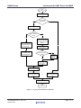
This function writes a byte to the serial port. It uses buffered output for low latency. If the SCI channel transmit data
register is currently empty, the write_data value gets copied directly into the data register and this function returns
immediately with a true result, indicating that the data was accepted. Otherwise, the data is stored in a transmit data
queue and then the function returns with a true result, indicating that the data was accepted. A global variable,
g_uart_tx_ready, is shared between the sci_put_char function and the transmit interrupt handler (see Hardware
Interrupts section) as a flag used to coordinate this activity between the two procedures.
This procedure maintains its own private queue position counter that is reset when sci_uart_init is executed. As each
byte is added to the transmit queue, the position in the queue is advanced and the count is incremented by one. If the top
address of the queue buffer is reached, the position pointer is reset back to the bottom address of the buffer.
Any data accumulated in the queue will be written out by the transmit interrupt handler, which will also take care of
decrementing the count. If the queue is full then this function returns immediately with a false result and the data is not
written.
Reentrant
•
No
Example
/* Transmit a character to the serial port */
result = sci_put_char('A');
Special Notes:
•
•
A call to sci_uart_init must have been completed once before calling this function.
Adjust baud rate and/or buffer size as required by the application to minimize queue full result.
R01AN0820EU0101 Rev.1.01
Oct 26, 2011
Page 6 of 14
RX630 Group
Interrupt-mode UART Driver for RX630
Start
sci_put_char
Enable TX interrupts
Transmit data
queue full?
No
Disable TX interrupts
TX data
register ready for a
char?
No
Yes
Write byte passed in
as argument directly
to TX data reg.
Set global
transmitter‐ready
flag variable false
Store the argument
byte in the transmit
queue at the current
position
Yes
Increment transmit
queue position
At top
of transmit data
queue?
Yes
Point back
to bottom
of queue
No
Increment queue
data count
Enable TX interrupts
Set result code true
Set result code false
Return the result code
End
sci_put_char
Figure 2. sci_put_char function flow diagram.
R01AN0820EU0101 Rev.1.01
Oct 26, 2011
Page 7 of 14
RX630 Group
8.3
Interrupt-mode UART Driver for RX630
sci_get_char
Fetches a byte from receive buffer.
Format
bool sci_get_char(uint8_t * read_data);
Parameters
read_data
Pointer to a location where the read data is to be copied to.
Return Values
Boolean result code:
True:
False:
Data was available; a character is returned in read_data argument..
No data was available; value of 0 is written to read_data argument .
Properties
Prototyped in file “uart.h”
Description
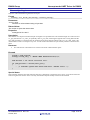
This function fetches one byte from a buffer that has been filled by the serial port receive interrupt handler. As the SCI
hardware receives new data on the serial bus, the receive ISR transfers the data into a circular queue in RAM (see
section on interrupt handlers). When the top address of the queue buffer is reached, the queue position wraps back to the
bottom address of the buffer and storage of the data continues. A count of the number of unread bytes is added to by the
receive data interrupt handler. The sci_get_char function decrements that count by one each time it is called.
Eventually, the count reaches 0, indicating that there is no more data in the receive queue to be processed. If the receive
queue contains unread data when sci_get_char is called, then the byte at the current queue pointer position is copied
into the location pointed to by the read_data argument, and the result code true is returned. If sci_get_char is called
when the queue is empty, then it sets the read data argument to zero and returns immediately with a false result code.
Reentrant
•
No
Example
Example showing this function being used.
static uint8_t old_char;
uint8_t new_char;
/* Read a received character. */
if(sci_get_char(&new_char)) /* Data is returned in new_char */
{
old_char = new_char;
/* Got a new character. Do something with it. */
}
else
{
/* No data was available. Try again later or report an error */
}
Special Notes:
A call to sci_uart_init must have been completed once before calling this function, otherwise no new data will ever be
read and the receive queue will remain empty.
Calling sci_get_char while the receive queue is empty can be avoided by first calling the function sci_read_count_get to
check for a non-zero count.
Limitations
If the receive queue is filled before the application can consume the data, new data received continues to be stored in
the queue, overwriting any unprocessed data remaining in that location. Normally, the application is expected to read
the data from the queue before that happens. With minor modifications, this behavior could optionally cause an error to
be flagged so that the application can be informed that data has been lost. The buffer sizes are easily modifiable through
a single #define statement. Currently, an overrun condition can be determined by comparing the read count value to the
buffer size value. If the read count is greater than the buffer size, then an overrun has occurred.
R01AN0820EU0101 Rev.1.01
Oct 26, 2011
Page 8 of 14
RX630 Group
Interrupt-mode UART Driver for RX630
Figure 3. sci_get_char function flow diagram.
R01AN0820EU0101 Rev.1.01
Oct 26, 2011
Page 9 of 14
RX630 Group
8.4
Interrupt-mode UART Driver for RX630
sci_write_str
Outputs a null terminated string from the serial port.
Format
uint32_t sci_write_str(uint8_t *source_string);
Parameters
*source_string
Pointer to a null terminated string of byte data.
Return Values
The number of bytes that were written.
Properties
Prototyped in file “uart.h”
Description
This function is a simple but useful example of a higher level procedure that can be built through use of the low-level
sci_put_char function. sci_write_str repeatedly calls sci_put_char, advancing through the source string data until the
zero (null) terminator is encountered or the transmit queue returns full (the internal call to sci_put_char( ) fails). The
null terminator itself is not output in any case. A count of the total number of bytes actually written is returned to the
caller.
Reentrant
•
No. This function causes data to be written to the serial UART transmit queue.
Example
uint32_t num_written;
uint8_t title_str[] = "RX630 UART Demonstration\r\n";
num_written = sci_write_str(title_str);
if (num_written < strlen(title_str))
{
... /* Transmit queue must have been full. Handle error. */
}
Special Notes:
If the transmit queue becomes full while this function is attempting to output the source string, it will abort before the
entire string has been written. In this case only the number of bytes actually written will be returned.
R01AN0820EU0101 Rev.1.01
Oct 26, 2011
Page 10 of 14
RX630 Group
8.5
Interrupt-mode UART Driver for RX630
sci_read_count_get
Gets the current count of unprocessed data in the received data queue.
Format
uint32_t sci_read_count_get(void);
Parameters
None.
Return Values
The number of un-read bytes remaining in the received data queue.
Properties
Prototyped in file “uart.h”
Description
sci_read_count_get is useful for checking to see how many bytes are in the receive buffer that have not yet been read
by the application. It can also be called before calling the sci_get_char function to avoid calling it when it is empty.
Reentrant
•
Yes
Example
/* Find out how much unprocessed data the receive queue is holding. */
num_in_rx_queue = sci_read_count_get()
if(num_in_rx_queue > (RX_QUEUE_SIZE / 2))
{
... /* Receive queue is over half full. Better start reading from it! */
}
R01AN0820EU0101 Rev.1.01
Oct 26, 2011
Page 11 of 14
RX630 Group
Interrupt-mode UART Driver for RX630
9. Hardware interrupt handlers
The SCI interrupt handlers work interactively with higher-level functions that fill data into a transmit queue and
consume data from a receive queue. In the case of both the transmit and receive queues, the buffer areas are treated as
circular buffers. This prevents buffer out-of-bounds problems by wrapping back to the beginning when the end of the
buffer is reached.
Start
SCI0_TXI0_isr
Data
present in transmit
queue?
No
Yes
Clear global
transmitter‐ready
flag variable to false
Disable TX
interrupts
Copy data at current
queue position to TX
data reg.
Set global
transmitter‐ready
flag variable true
Increment transmit
queue position
Pointing
to top of transmit
data queue?
Yes
Point to
bottom of
queue
Decrement queue
data count
exit
SCI0_TXI0_isr
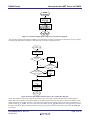
Figure 4. Transmit data buffer empty interrupt service routine flow diagram.
This ISR is invoked when the SCI channel transmit data register empty interrupt request is generated. When the
application has data to transmit, the sci_put_char function gets called, which places the data directly into the SCI
transmit data register (if transmit operation is currently idle) or into the transmit data queue if the SCI is currently in the
process of transmitting. When a byte in the transmit data register has been transferred to the serial shift register, the data
register becomes available to accept new data and an interrupt request is generated, resulting in this transmit ISR being
invoked again. A global variable, g_uart_tx_ready, is shared between the sci_put_char function and this interrupt as
a flag used to coordinate the interaction between these two procedures.
If the transmit queue contains data to send, this ISR reads a byte from the queue and copies it to the transmit data
register. This procedure maintains its own private queue position counter that is reset when sci_uart_init is executed.
As data is retrieved from the queue the position is advanced. If the top address of the queue buffer is reached, the queue
position wraps back to the bottom address of the buffer and data fetches continue from that location onward. A running
count of the number of bytes contained in the transmit queue is maintained in a global variable: g_tx_count. The count
value is decremented by this procedure until it reaches 0. When the count reaches 0, this routine disables further
interrupts and sets a global status flag to indicate that it is ready for more data.
R01AN0820EU0101 Rev.1.01
Oct 26, 2011
Page 12 of 14
RX630 Group
Interrupt-mode UART Driver for RX630
Figure 5. Transmit Completed interrupt service routine flow diagram.
The transmit complete (TEI) interrupt handler is invoked when a transmit operation has completed. It just sets a global
status flag that indicates the hardware is idle and ready for another transmit operation.
Start
SCI0_RXI0_isr
Read RX data reg
into local variable
RX buffer
overflow?
Yes
Clear Error
Yes
ORER
bit still set?
No
No
(pipelining)
Pointing
to top of received
data queue?
Yes
Point to
bottom of
queue
No
Copy data into
queue at current
position
Increment queue
position and data
count
exit
SCI0_RXI0_isr
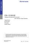
Figure 6. Receive data buffer full interrupt service routine flow diagram.
As the SCI hardware receives new data on the serial bus, the receive ISR transfers the data into a circular queue in
RAM. When the top address of the queue buffer is reached, the queue position wraps back to the bottom address of the
buffer and storage of the data continues. A running count of the number of bytes copied to the queue is maintained in a
global variable: g_rx_count. The count value is decremented by the sci_get_char function as the application processes
the data in the queue. This procedure maintains its own private queue position counter that is reset when sci_uart_init
is executed.
R01AN0820EU0101 Rev.1.01
Oct 26, 2011
Page 13 of 14
RX630 Group
Interrupt-mode UART Driver for RX630
Website and Support
Renesas Electronics Website
http://www.renesas.com/
Inquiries
http://www.renesas.com/inquiry
All trademarks and registered trademarks are the property of their respective owners.
R01AN0820EU0101 Rev.1.01
Oct 26, 2011
Page 14 of 14
Revision Record
Rev.
1.00
1.01
Date
Oct.04.2011
Oct.27.2011
Description
Page
Summary
—
First draft released
—
Moved into new document template and minor edits.
A-1
General Precautions in the Handling of MPU/MCU Products
The following usage notes are applicable to all MPU/MCU products from Renesas. For detailed usage notes on the
products covered by this document, refer to the relevant sections of the document as well as any technical updates that
have been issued for the products.
1. Handling of Unused Pins
Handle unused pins in accord with the directions given under Handling of Unused Pins in the manual.
⎯ The input pins of CMOS products are generally in the high-impedance state. In operation with an
unused pin in the open-circuit state, extra electromagnetic noise is induced in the vicinity of LSI, an
associated shoot-through current flows internally, and malfunctions occur due to the false
recognition of the pin state as an input signal become possible. Unused pins should be handled as
described under Handling of Unused Pins in the manual.
2. Processing at Power-on
The state of the product is undefined at the moment when power is supplied.
⎯ The states of internal circuits in the LSI are indeterminate and the states of register settings and
pins are undefined at the moment when power is supplied.
In a finished product where the reset signal is applied to the external reset pin, the states of pins
are not guaranteed from the moment when power is supplied until the reset process is completed.
In a similar way, the states of pins in a product that is reset by an on-chip power-on reset function
are not guaranteed from the moment when power is supplied until the power reaches the level at
which resetting has been specified.
3. Prohibition of Access to Reserved Addresses
Access to reserved addresses is prohibited.
⎯ The reserved addresses are provided for the possible future expansion of functions. Do not access
these addresses; the correct operation of LSI is not guaranteed if they are accessed.
4. Clock Signals
After applying a reset, only release the reset line after the operating clock signal has become stable.
When switching the clock signal during program execution, wait until the target clock signal has
stabilized.
⎯ When the clock signal is generated with an external resonator (or from an external oscillator)
during a reset, ensure that the reset line is only released after full stabilization of the clock signal.
Moreover, when switching to a clock signal produced with an external resonator (or by an external
oscillator) while program execution is in progress, wait until the target clock signal is stable.
5. Differences between Products
Before changing from one product to another, i.e. to a product with a different part number, confirm
that the change will not lead to problems.
⎯ The characteristics of an MPU or MCU in the same group but having a different part number may
differ in terms of the internal memory capacity, layout pattern, and other factors, which can affect
the ranges of electrical characteristics, such as characteristic values, operating margins, immunity
to noise, and amount of radiated noise. When changing to a product with a different part number,
implement a system-evaluation test for the given product.
Notice
1.
All information included in this document is current as of the date this document is issued. Such information, however, is subject to change without any prior notice. Before purchasing or using any Renesas
Electronics products listed herein, please confirm the latest product information with a Renesas Electronics sales office. Also, please pay regular and careful attention to additional and different information to
be disclosed by Renesas Electronics such as that disclosed through our website.
2.
Renesas Electronics does not assume any liability for infringement of patents, copyrights, or other intellectual property rights of third parties by or arising from the use of Renesas Electronics products or
technical information described in this document. No license, express, implied or otherwise, is granted hereby under any patents, copyrights or other intellectual property rights of Renesas Electronics or
others.
3.
You should not alter, modify, copy, or otherwise misappropriate any Renesas Electronics product, whether in whole or in part.
4.
Descriptions of circuits, software and other related information in this document are provided only to illustrate the operation of semiconductor products and application examples. You are fully responsible for
the incorporation of these circuits, software, and information in the design of your equipment. Renesas Electronics assumes no responsibility for any losses incurred by you or third parties arising from the
use of these circuits, software, or information.
5.
When exporting the products or technology described in this document, you should comply with the applicable export control laws and regulations and follow the procedures required by such laws and
regulations. You should not use Renesas Electronics products or the technology described in this document for any purpose relating to military applications or use by the military, including but not limited to
the development of weapons of mass destruction. Renesas Electronics products and technology may not be used for or incorporated into any products or systems whose manufacture, use, or sale is
prohibited under any applicable domestic or foreign laws or regulations.
6.
Renesas Electronics has used reasonable care in preparing the information included in this document, but Renesas Electronics does not warrant that such information is error free. Renesas Electronics
7.
Renesas Electronics products are classified according to the following three quality grades: "Standard", "High Quality", and "Specific". The recommended applications for each Renesas Electronics product
assumes no liability whatsoever for any damages incurred by you resulting from errors in or omissions from the information included herein.
depends on the product's quality grade, as indicated below. You must check the quality grade of each Renesas Electronics product before using it in a particular application. You may not use any Renesas
Electronics product for any application categorized as "Specific" without the prior written consent of Renesas Electronics. Further, you may not use any Renesas Electronics product for any application for
which it is not intended without the prior written consent of Renesas Electronics. Renesas Electronics shall not be in any way liable for any damages or losses incurred by you or third parties arising from the
use of any Renesas Electronics product for an application categorized as "Specific" or for which the product is not intended where you have failed to obtain the prior written consent of Renesas Electronics.
The quality grade of each Renesas Electronics product is "Standard" unless otherwise expressly specified in a Renesas Electronics data sheets or data books, etc.
"Standard":
Computers; office equipment; communications equipment; test and measurement equipment; audio and visual equipment; home electronic appliances; machine tools;
personal electronic equipment; and industrial robots.
"High Quality": Transportation equipment (automobiles, trains, ships, etc.); traffic control systems; anti-disaster systems; anti-crime systems; safety equipment; and medical equipment not specifically
designed for life support.
"Specific":
Aircraft; aerospace equipment; submersible repeaters; nuclear reactor control systems; medical equipment or systems for life support (e.g. artificial life support devices or systems), surgical
implantations, or healthcare intervention (e.g. excision, etc.), and any other applications or purposes that pose a direct threat to human life.
8.
You should use the Renesas Electronics products described in this document within the range specified by Renesas Electronics, especially with respect to the maximum rating, operating supply voltage
range, movement power voltage range, heat radiation characteristics, installation and other product characteristics. Renesas Electronics shall have no liability for malfunctions or damages arising out of the
use of Renesas Electronics products beyond such specified ranges.
9.
Although Renesas Electronics endeavors to improve the quality and reliability of its products, semiconductor products have specific characteristics such as the occurrence of failure at a certain rate and
malfunctions under certain use conditions. Further, Renesas Electronics products are not subject to radiation resistance design. Please be sure to implement safety measures to guard them against the
possibility of physical injury, and injury or damage caused by fire in the event of the failure of a Renesas Electronics product, such as safety design for hardware and software including but not limited to
redundancy, fire control and malfunction prevention, appropriate treatment for aging degradation or any other appropriate measures. Because the evaluation of microcomputer software alone is very difficult,
please evaluate the safety of the final products or system manufactured by you.
10. Please contact a Renesas Electronics sales office for details as to environmental matters such as the environmental compatibility of each Renesas Electronics product. Please use Renesas Electronics
products in compliance with all applicable laws and regulations that regulate the inclusion or use of controlled substances, including without limitation, the EU RoHS Directive. Renesas Electronics assumes
no liability for damages or losses occurring as a result of your noncompliance with applicable laws and regulations.
11. This document may not be reproduced or duplicated, in any form, in whole or in part, without prior written consent of Renesas Electronics.
12. Please contact a Renesas Electronics sales office if you have any questions regarding the information contained in this document or Renesas Electronics products, or if you have any other inquiries.
(Note 1)
"Renesas Electronics" as used in this document means Renesas Electronics Corporation and also includes its majority-owned subsidiaries.
(Note 2)
"Renesas Electronics product(s)" means any product developed or manufactured by or for Renesas Electronics.
http://www.renesas.com
SALES OFFICES
Refer to "http://www.renesas.com/" for the latest and detailed information.
Renesas Electronics America Inc.
2880 Scott Boulevard Santa Clara, CA 95050-2554, U.S.A.
Tel: +1-408-588-6000, Fax: +1-408-588-6130
Renesas Electronics Canada Limited
1101 Nicholson Road, Newmarket, Ontario L3Y 9C3, Canada
Tel: +1-905-898-5441, Fax: +1-905-898-3220
Renesas Electronics Europe Limited
Dukes Meadow, Millboard Road, Bourne End, Buckinghamshire, SL8 5FH, U.K
Tel: +44-1628-585-100, Fax: +44-1628-585-900
Renesas Electronics Europe GmbH
Arcadiastrasse 10, 40472 Düsseldorf, Germany
Tel: +49-211-65030, Fax: +49-211-6503-1327
Renesas Electronics (China) Co., Ltd.
7th Floor, Quantum Plaza, No.27 ZhiChunLu Haidian District, Beijing 100083, P.R.China
Tel: +86-10-8235-1155, Fax: +86-10-8235-7679
Renesas Electronics (Shanghai) Co., Ltd.
Unit 204, 205, AZIA Center, No.1233 Lujiazui Ring Rd., Pudong District, Shanghai 200120, China
Tel: +86-21-5877-1818, Fax: +86-21-6887-7858 / -7898
Renesas Electronics Hong Kong Limited
Unit 1601-1613, 16/F., Tower 2, Grand Century Place, 193 Prince Edward Road West, Mongkok, Kowloon, Hong Kong
Tel: +852-2886-9318, Fax: +852 2886-9022/9044
Renesas Electronics Taiwan Co., Ltd.
13F, No. 363, Fu Shing North Road, Taipei, Taiwan
Tel: +886-2-8175-9600, Fax: +886 2-8175-9670
Renesas Electronics Singapore Pte. Ltd.
1 harbourFront Avenue, #06-10, keppel Bay Tower, Singapore 098632
Tel: +65-6213-0200, Fax: +65-6278-8001
Renesas Electronics Malaysia Sdn.Bhd.
Unit 906, Block B, Menara Amcorp, Amcorp Trade Centre, No. 18, Jln Persiaran Barat, 46050 Petaling Jaya, Selangor Darul Ehsan, Malaysia
Tel: +60-3-7955-9390, Fax: +60-3-7955-9510
Renesas Electronics Korea Co., Ltd.
11F., Samik Lavied' or Bldg., 720-2 Yeoksam-Dong, Kangnam-Ku, Seoul 135-080, Korea
Tel: +82-2-558-3737, Fax: +82-2-558-5141
© 2011 Renesas Electronics Corporation. All rights reserved.
Colophon 1.1