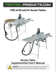
1
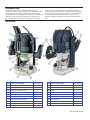
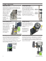
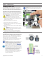
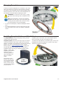
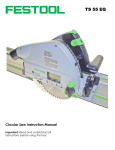
The OF 2200 EB Plunge Router
Plunge Router
Supplemental User’s Manual
WARNING: To reduce the risk of serious or fatal injury, read and understand
all safety precautions and instructions in this manual before using this tool.
Limited Warranty
30 Day Money Back Guarantee
We are so confident that you will thoroughly enjoy our tools, that
we offer a 30 day money back guarantee. If you are not
completely satisfied, your full purchase price will be refunded,
excluding all freight charges.
1+2 Limited Warranty
Festool USA offers a 3-year limited warranty, one of the longest
in the industry. This warranty is valid on the pre-condition that
the tool is used and operated in compliance with the Festool
operating instructions. Festool USA warrants that the specified
tool will be free from defects in materials and workmanship for a
term of 3 years from the date of purchase.
Conditions of 1+2 Limited Warranty
You are entitled to a free extended limited warranty (1 year + 2
years = 3 Years) for your Festool power tool. Festool USA is
responsible for all shipping costs during the first year of the
warranty. During the second and third year of the warranty, the
customer is responsible for shipping the tool to Festool. Festool
will pay for return shipping to the customer using UPS Ground
Service. All warranty service is valid 3 years from the date of
purchase on your receipt or invoice.
Excluded from the coverage under this warranty are: normal
wear and tear, damages caused by misuse, abuse, or neglect;
damage caused by anything other than defects in material and
workmanship. This warranty does not apply to accessory items
such as circular saw blades, drill bits, router bits, jigsaw blades,
sanding belts, and grinding wheels. Also excluded are "wearing
parts," such as carbon brushes, lamellas of air tools, rubber
collars and seals, sanding discs and pads, batteries, and Festool
gear (hats and t shirts).
The obligations of Festool USA in its sole discretion under this
warranty shall be limited to repair or replacement or a refund of
the purchase price for any Festool portable power tool that is
found to have a defect in materials or workmanship during the
warranty period. FESTOOL USA SHALL NOT BE LIABLE FOR ANY
CONSEQUENTIAL, INCIDENTAL OR SPECIAL DAMAGES
REGARDLESS OF THE THEORY OF LAW ON WHICH THE CLAIM IS
BASED. ALL WARRANTIES IMPLIED BY STATE LAW, INCLUDING
THE IMPLIED WARRANTIES OR MERCHANTABILITY AND FITNESS
FOR A PARTICULAR PURPOSE ARE HEREBY LIMITED TO THE
DURATION OF THREE YEARS.
Some states in the U.S. and some Canadian provinces do not
allow the limitations on how long an implied warranty lasts, so
the above limitation may not apply to you. This warranty gives
you specific legal rights, and you may also have other rights that
vary from state to state in the U.S. and from province to province
in Canada.
With the exception of any warranties implied by state or province
law as limited above, the foregoing express limited warranty is
exclusive and in lieu of all other warranties, guarantees,
agreements, and similar obligations of Festool USA. Festool USA
makes no other warranty, express or implied, for Festool portable
power tools. No agent, representative, distributor, dealer, or
employee of Festool USA has the authority to increase or
otherwise change the obligations or limitations of this warranty.
Repairs
If your Festool power tools require repair, you must contact our
Service Department at (800) 554-8741 for authorization and
address details. No collect shipments will be accepted. No Festool
hats, t-shirts or other wearables may be returned. Also contact
our Service Department at the telephone number listed above if
you have any questions about warranty claim procedures.
Returns
If you need to return your Festool tools for any reason, please return it to the dealer from which you originally bought the tool.
Liability Statement
This product has been built to the high standards of Festool.
Please do not attempt to operate or repair this equipment without
adequate training. Any use, operation, or repair in contravention
of this document is at your own risk. By acceptance of this
system you hereby assume all liability consequent to your use or
misuse of this equipment. Festool USA assumes no liability for
incidental, special, or consequential damage of any kind.
Equipment specifications, applications, and options are subject to
change at the sole discretion of Festool USA without notice.
Proprietary Notice
All drawings and information herein are the property of Festool,
TTS Tooltechnic Systems AG & Co. KG. All unauthorized use and
reproduction is prohibited.
Written and Illustrated by Rick Christopherson.
© 2009 TTS Tooltechnic Systems AG & Co. KG
All rights reserved. Printed in the United States of America and
Germany.
2
Festool USA is a division of Tooltechnic Systems, LLC.
Festool is a trademark and service mark of TTS Tooltechnic
Systems AG & Co. KG
Plug-It and Systainer are registered trademarks of TTS
Tooltechnic Systems AG & Co. KG
www.festoolusa.com
OF 2200 EB Router
Contents
Limited Warranty .............................................2
30 Day Money Back Guarantee ......................... 2
1+2 Limited Warranty ..................................... 2
Conditions of 1+2 Limited Warranty .................. 2
Repairs ......................................................... 2
Returns......................................................... 2
Liability Statement ......................................... 2
Proprietary Notice........................................... 2
About This Manual............................................3
Tool Symbols ................................................. 3
General Power Tool Safety Warnings ...............4
Work Area Safety ........................................ 4
Electrical Safety .......................................... 4
Personal Safety........................................... 4
Power Tool Use and Care.............................. 4
Service ...................................................... 5
Specific Safety Rules for Routers ...................... 5
Respiratory Exposure Safety Warnings .............. 5
Tool Description ...............................................5
Technical Specifications ................................... 5
Intended Use ................................................. 6
Overview....................................................... 6
Power Controls............................................... 7
Router Speed and Feed Rate......................... 7
Dust Collection .............................................. 7
Plunge Components ........................................ 8
Depth Stop Turret ....................................... 8
Turret Latching Lever................................... 8
Fine Adjustment Dial ................................... 8
Plunge Depth Gauge .................................... 8
Plunge Lock Knob ........................................ 8
Depth Stop Locking Lever and Post ................ 8
Basic Operation ................................................9
Changing Router Bits ...................................... 9
Changing Collets ......................................... 9
Setting the Plunge Depth ............................... 10
Offset from a Surface ................................. 10
By Router Bit Profile................................... 10
Changing Baseplates ..................................... 11
Installing Template Guides and Chip Deflector .. 11
Basic Routing .................................................12
Feed Direction Rules ..................................... 12
Fixed Depth Routing...................................... 12
Fixed Depth Using the Turret Latch ................. 13
Plunge Routing ............................................. 13
Plough Cuts .............................................. 13
Using a Template Guide ................................. 14
Advanced Routing Techniques........................14
Multi-pass Cuts............................................. 14
Multi-depth Ploughing ................................ 14
Multi-depth Profiles .................................... 15
Multi-position (horizontal) Profiles ................ 15
Pre-cutting Dovetails and Keyways............... 15
Precision Routing .......................................... 16
Tips for Successful Routing............................. 17
Chipping and Tearout ................................. 17
Chatter .................................................... 17
Router Control .......................................... 17
Climb-Cut Routing ........................................ 18
What is Climb-Cutting ................................ 18
Notes and Tips .......................................... 18
Accessories ....................................................19
Guide Rail Attachment ................................... 19
Edge Guide .................................................. 20
Systainer (System Container) ......................... 21
Troubleshooting .............................................22
Maintenance...................................................23
Routine Maintenance ..................................... 23
About This Manual
Save These Instructions
It is important for you to read and understand this manual. The
information it contains relates to protecting YOUR SAFETY and
PREVENTING PROBLEMS. The symbols below are used to help you
recognize this information.
WARNING!
Indicates a potentially hazardous
situation which, if not avoided, could
result in death or serious injury.
CAUTION!
Indicates a potentially hazardous
situation which, if not avoided, could
result in minor or moderate injury.
NOTICE:
Indicates a potential situation which, if
not avoided, can result in property
damage or damage to the tool.
Note:
Indicates information, notes, or tips for
improving your success using the tool.
Supplemental User’s Manual
Tool Symbols
V
W
Hz
~
no
Ø
Volts
Watts
Hertz
Alternating Current (AC)
No-load Speed
Diameter
Class II Double Insulated
3
General Power Tool Safety Warnings
WARNING! Read all safety warnings and instructions.
Failure to follow the warnings and instructions may result in
electric shock, fire, and/or serious injury.
Save all warnings and instructions for future
reference.
Work Area Safety
►
►
or dust. Power tools create sparks which may ignite the
dust or fumes.
Keep your work area clean and well lit. Cluttered or
dark work areas invite accidents.
Do not operate power tools in explosive atmospheres,
such as in the presence of flammable liquids, gases,
►
Keep children and bystanders away while operating a
power tool. Distractions can cause you to lose control.
Electrical Safety
►
►
►
►
►
Power tool plugs must match the outlet. Never modify
the plug in any way. Do not use any adapter plugs
with earthed (grounded) power tools. Unmodified plugs
and matching outlets will reduce risk of electric shock.
Avoid body contact with earthed or grounded surfaces
such as pipes, radiators, ranges and refrigerators.
There is an increased risk of electric shock if your body is
earthed or grounded.
Do not expose power tools to rain or wet conditions.
Water entering a power tool will increase the risk of electric
shock.
►
►
►
►
Do not abuse the cord. Never use the cord for
carrying, pulling, or unplugging the power tool. Keep
cord away from heat, oil, sharp edges or moving
parts. Damaged or entangled cords increase the risk of
electric shock.
If operating a power tool in a damp location is
unavoidable, use a ground fault circuit interrupter
(GFCI) protected supply. Use of a GFCI reduces the risk
of electric shock.
Never use an extension cord that is damaged,
including cuts, exposed wires, or bent/missing
prongs. Damaged extension cords increase the risk of fire
or electric shock.
Use only extension cords rated for the purpose.
Use only extension cords rated for the amperage of
this tool and the length of the cord. Using too small of
an extension cord can cause the cord to overheat.
Extension Cord Ratings
Cord Length
Size (AWG)
<50 Ft.
14
50-100 Ft.
12
>100 Ft.
Not
recommended
When operating a power tool outdoors, use an
extension cord suitable for outdoor use. Use of a cord
for outdoor use reduces the risk of electric shock.
Personal Safety
►
►
►
►
Stay alert, watch what you are doing, and use
common sense when operating a power tool. Do not
use a power tool while tired or under the influence of
drugs, alcohol, or medication. A moment of inattention
while operating power tools may result in serious personal
injury.
Use personal protective equipment. Always wear eye
protection. Protective equipment such as dust mask, nonskid safety shoes, hard hat, or hearing protection used for
appropriate conditions will reduce personal injuries.
Prevent unintentional starting. Ensure the switch is in
the off-position before connecting to power source,
picking up, or carrying the tool. Carrying power tools
with your finger on the switch or energizing power tools that
have the switch on invites accidents.
power tool on. A wrench or a key that is left attached to a
rotating part of the tool may result in personal injury.
►
►
►
►
Remove adjusting key or wrench before turning the
Do not overreach. Keep proper footing and balance at
all times. This enables better control of the tool in
unexpected situations.
Dress properly. Do not wear loose clothing or jewelry.
Keep your hair, clothing, and gloves away from
moving parts. Loose clothes, jewelry, or long hair can be
caught in moving parts.
If devices are provided for the connection of dust
extraction and collection facilities, ensure these are
connected and properly used. Use of dust collection can
reduce dust-related hazards.
Always wear safety glasses complying with ANSI
Z87.1. Ordinary glasses are not proper protection.
Power Tool Use and Care
►
►
►
►
4
Do not force the power tool. Use the correct power
tool for your application. The correct power tool will do
the job better and safer at the rate for which it is designed.
instructions to operate the power tool. Power tools are
dangerous in the hands of untrained users.
►
Do not use the power tool if the switch does not turn
it on and off. Any power tool that cannot be controlled with
the switch is dangerous and must be repaired.
Disconnect the plug from the power source before
making any adjustments, changing accessories, or
storing the tool. Such preventive safety measures reduce
the risk of starting the tool accidentally.
Store idle tools out of reach of children and do not
allow persons unfamiliar with the power tool or these
►
Maintain power tools. Check for misalignment or
binding of moving parts, breakage of parts and any
other condition that may affect the power tool’s
operation. If damaged, have the power tool repaired
before use. Many accidents are caused by poorly
maintained power tools.
Keep cutting tools sharp and clean. Properly maintained
tools with sharp cutting edges are less likely to bind and are
easier to control.
OF 2200 EB Router
►
Use the power tool, accessories, and tool bits etc. in
accordance with these instructions, taking into
account the working conditions and the work to be
performed. Use of the power tool for operations different
from those intended could result in a hazardous situation.
►
To reduce the risk of fatal or serious injury, never
alter or misuse the power tool.
Service
►
Have your power tool serviced by a qualified repair
person using only identical replacement parts. This
will ensure that the safety of the power tool is maintained.
Specific Safety Rules for Routers
►
►
►
►
►
►
►
►
Hold the tool by the insulated gripping surfaces when
performing an operation where the cutting tool may
contact hidden wiring or its own cord. Contact with a
“live” wire will make the exposed metal parts of the tool
“live” and shock the operator.
Use clamps or another practical way to secure and
support the workpiece to a stable platform. Holding the
work by hand or against your body leaves it unstable and
may lead to loss of control.
►
►
►
This tool is intended for router bits not to exceed
89mm (3.5 inches). Using too large of a router bit will
result in the router bit striking the base of the tool, and may
also lead to a loss of control.
►
The router bit shank must fit the size of the collet.
Using a router bit that cannot be firmly gripped by the collet
will result in the router bit coming loose, and may result in
serious personal injury.
►
Do not exceed the router bit manufacturer’s maximum
speed rating of the router bit.
Always make sure the work surface is free from nails
and other foreign objects. Cutting into foreign objects
can cause the router bit and/or the object to break apart
and strike the operator.
Keep both hands on the router handles during
operation. Firmly controlling the router reduces the risk for
loss of control and injury.
►
►
►
NEVER hold the piece being cut in your hands or
across your leg. It is important to support the work
properly to minimize body exposure or loss of control.
Keep hands and body away from the cutting area or
below the router base.
Before using the router, make sure the collet nut and
any other adjustment devices are securely tightened.
A loose adjustment device can unexpectedly shift, causing
loss of control, and loose rotating components can be
violently thrown.
Never start the tool when the bit is engaged in the
workpiece. The cutting bit may grab and cause loss of
control.
Never use dull or damaged router bits. Damaged bits
may break during use, and dull bits require additional force
to operate, which may cause the bit to break or a loss of
control.
Never operate the router with the cutting tool
engaged in the workpiece without locking the plunge
lock knob. Unexpected changes in cutting depth can result
in a loss of control.
Do not set the router down until the motor has come
to a complete stop. The exposed spinning bit can cause
serious injury or cause the router to move unexpectedly.
To reduce the risk of burn injury, do not touch the
router bit immediately after use. The router bit may get
hot during use.
Always unplug the tool before changing bits or
making adjustments. Failure to do so can result in the
tool starting unexpectedly.
Respiratory Exposure Safety Warnings
Substantial or repeated inhalation of dust and other airborne
contaminants, in particular those with a smaller particle size,
may cause respiratory or other illnesses. Various dusts
created by power sanding, sawing, grinding, drilling and other
construction activities contain chemicals or substances known
(to the State of California and others) to cause cancer, birth
defects or other reproductive harm. Some examples of these
chemicals/substances are:
►
►
lead from lead-based paints;
crystalline silica from bricks, cement, and other masonry
products;
►
►
arsenic and chromium from chemically-treated lumber; and
some wood dusts, especially from hardwoods, but also from
some softwoods such as Western Red Cedar.
The risk from these exposures varies, depending on how often
you do this type of work. To reduce your exposure to these
chemicals: work in a well ventilated area and use a properly
functioning dust extraction system. When the inhalation of
dust cannot be substantially controlled, i.e., kept at or near
the ambient (background) level, the operator and any
bystanders should wear a respirator approved by NIOSH for
the type of dust encountered.
Tool Description
Technical Specifications
Power Consumption
15 amps @ 120 volts
Maximum Bit Diameter
89 mm (3.5”)
Motor Speed
10,000 – 22,000 RPM (no load)
Collet Nut Size
M22 x 1
Plunge Range
80 mm (3.1”)
Weight
7.8 kg (17.2 lbs)
Fine Height Adjustment
20 mm (0.8”)
All metric dimensions are controlling.
Supplemental User’s Manual
5
Intended Use
The OF 2200 EB router is designed exclusively for
machining of wood, wood-like materials, and plastics. The
router may also be used for machining aluminum and
plasterboard when an appropriate router bit is installed. All
applications beyond this are regarded as improper use.
The tool should not be altered or used for any purpose
other than as specified in these operating instructions.
Using the tool in contravention to this manual may lead to
serious injury and will void your warranty. The user shall
be responsible and liable for accidents, injuries, and
property damage resulting from misuse or abuse of this
tool.
Overview
Item Name or Description
6
Ref. Page(s)
Item Name or Description
Ref. Page(s)
A
Guide Rod Clamping Knob
19, 20
K
Ratcheting Spindle Lock
9
B
Guide Rod Eyelet
19, 20
L
Collet
9
C
Baseplate Release Lever
11
M
Handle
12
Trigger Lock
7
D
Depth Stop Turret
8, 10
N
E
Turret Latching Lever
8, 10
O
Power Trigger
7
F
Depth Stop Post
8, 10
P
Dust Shroud Release Lever
7
G
Depth Stop Locking Lever
8, 10
Q
Dust Shroud
7
H
Depth Stop Post Handle
8, 10
R
Plunge Lock Knob
8, 10, 12
I
Fine Adjustment Dial
8, 10
S
Dust Collection Port
7
J
Speed Control Dial
7
OF 2200 EB Router
Power Controls
To operate the router:
1. Set the motor speed by turning the variable speed
control knob to the desired speed according to the
Router Speed Settings table below.
2. Start the router by pulling in on the power trigger.
3. If desired, lock the power trigger in the On position
by holding in the trigger lock button, and then release
the power trigger.
4. To release the trigger lock, pull in and then release
the power trigger.
Router Speed and Feed Rate
The optimal router speed for an operation is determined
by the diameter of the router bit and the type of material
being machined. The important factor is the speed that
the router bit tips move past the workpiece. The tip
speed is proportional to the diameter of the router bit.
If the tip speed is too high, friction causes excessive heat
and the workpiece can be scorched. Too low of a tip
speed and the bit will tear the material instead of cutting
(for aluminum, the bit will grab the workpiece).
The feed rate of the router past the workpiece is a
function of the router speed, material type, and amount
of material being removed. Too fast of a feed rate can
cause chatter and tearout. Too slow of a feed rate can
burn or scorch the workpiece.
Material
Pine
Oak
Cherry
Maple
Particleboard
and MDF
Soft Plastics
Hard Plastics
Aluminum
Router Speed Settings
Bit Diameter (inches)
≤½
¾
1
1¼
≥1½
5-6 5-6 4-6 3-5
3-5
5-6
4-6 4-5 3-5
2-4
3-5
3-5 3-4 2-4
2-3
3-5
3-5 3-4 2-4
2-3
Fast
Moderate
Moderate
Slow
5-6
5-6
4-6
3-5
3-5
Fast
3-5
2-4
3-4
3-5
1-4
3-4
3-4
1-3
2-3
2-4
1-2
2-3
1-3
1-2
1-3
Slow
Slow
Slow
Feed
Dust Collection
Note: The OF 2200 router can be connected to the power
outlet of a Festool CT-class dust extractor; however, the
more load that is on the router, the more power it will
draw. If the router is drawing nearly it’s full load power, it
may be necessary to connect the router to a separate
electrical circuit from the dust extractor to prevent the
electrical circuit from being overloaded.
Note: When routing plastics, there may be a significant
buildup of static charge in the material and the router. To
minimize nuisance static shocks, it is best to use an antistatic dust extractor hose.
The OF 2200 router was designed to have excellent dust collection capabilities.
The integral dust collection port extracts dust right at the point of generation—
near the router bit. The retractable dust shroud helps prevent dust from
escaping the work area, and the optional chip deflector helps capture dust while
edge routing.
The dust shroud is spring loaded and
latches in the retracted position. To raise
the shroud, lift it up until it clicks into
position. To lower the shroud, press the
release lever.
To use the Chip Deflector, refer to the
“Installing Template Guides” section on
page 11.
Supplemental User’s Manual
7
Plunge Components
Depth Stop Turret
Plunge Depth Gauge
The depth stop turret has four positions, each with a
different height, or offset from the base position. The
desired final routing depth is set for the base position,
and the four offset positions
allow for incremental
depths to reach the final
depth. The 2mm offset
position is used to
provide for a final
cleanup pass. The
first adjustable
offset allows for a 6
to 18 mm range and
the upper
adjustable offset
allows for a 18 to 51
mm range.
The plunge depth gauge shows the
position of the depth stop post.
When the index pointer is reset to
zero at a depth position, the gauge
will show the change in depth as the
depth stop post is raised.
Turret Latching Lever
Plunge Lock Knob
The turret latching lever locks the
depth stop post to the center pin
of the turret when the
turret is in the Base
Position. This permits the
router height to be
controlled by the Fine
Adjustment Dial (see
below) and the router
to remain in the
plunged position
without the plunge
lock engaged.
The plunge lock knob locks the
router in a plunged position. To
lock the plunge, rotate the knob
counterclockwise. To unlock the
plunge, turn the knob
clockwise.
Fine Adjustment Dial
Depth Stop Locking Lever and Post
The fine adjustment dial raises and lowers the depth
stop post for making very precise depth setting
changes. Each click of the dial represents a 0.1 mm
change, and a full rotation is equal to 1.0 mm.
The depth stop locking lever clamps down on the depth stop
post to keep it from moving. The locking lever is located on
the fine adjustment cylinder, so that fine adjustments can
still be made when the post is clamped. To engage the lock,
turn the handle clockwise, and to release the lock, turn the
handle counterclockwise.
The index ring can be rotated separately to zero out the
index numbers at a starting point to make it easier to
determine changes in height.
8
One example of this is to use the
surface of a workpiece as the zero
point, and then use the gauge to set
the depth of the cut below the
surface. This is described on page 10.
Note that the plunge
lock needs to be
released while using
the Turret Latching
Lever and Fine
Adjustment Dial.
OF 2200 EB Router
Basic Operation
Changing Router Bits
The OF 2200 EB has the unique feature of a ratcheting
spindle lock. Because the spindle lock is ratcheted, you
don't need to remove the wrench to make multiple turns of
the collet nut; simply move the wrench back and forth.
NOTICE: Do not tighten the collet nut without a
router bit in the collet. Doing so will distort the
collet.
The router also has an extremely deep spindle bore (3 ½
inches/89 mm). Very few router bits are long enough to
bottom out in the spindle, which would prevent them from
tightening properly. The router bit gripping surface of the
collet is approximately 1 inch deep (shown below).
WARNING! To reduce the risk of injury, unplug
the router before changing the router bit.
1. Insert the router bit into the collet at least one inch.
This will vary with different bits, but most of the shank
should be within the collet.
2. Place the collet wrench on the collet nut.
3. Press the left-hand side of the spindle lock.
4. Tighten the collet nut firmly, but it is not necessary to
over-tighten the nut.
5. Remove the wrench from the collet nut before starting
the router.
WARNING! To reduce the risk of injury, never
operate the router without properly securing the
router bit in the collet.
6. To remove a router bit, follow the same procedure
except press the right-hand side of the spindle lock.
Changing Collets
The router can use a variety of router bits with different
shank diameters by changing the collet. The router can use
1/4-in., 3/8-in., 1/2-in., and 8mm collets. The collet is
integral with the collet nut, so unscrewing the collet nut
will pull the collet out of the tapered spindle.
To change collets, unscrew the existing collet all the way
out of the spindle and screw the new collet into the
spindle.
NOTICE: Avoid leaving a router bit installed in the
collet for long periods of time (during storage),
because the bit and collet can stick together and
be difficult to separate. Refer to the Maintenance
section on page 23 for collet maintenance.
Note: The collet is held into the collet nut with an
O-ring. The collet can be separated from the collet
nut only when there is no router bit in the collet. If
you inadvertently separate the collet from the nut,
press the collet into the nut until it snaps in
position, and then gently pack the O-ring in
between the collet and the nut with a small, blunt
tool. Avoid removing the collet from the nut,
except for maintenance.
Supplemental User’s Manual
9
Setting the Plunge Depth
Offset from a Surface
Setting the plunge depth as an offset from a surface is
used when making plough or dado cuts at a specific
depth below the surface of the workpiece.
7. If desired, you may use the fine adjustment dial to fine
tune the setting.
2. Rotate the turret to the base position.
The resulting gap between the depth stop post and the
turret represents the depth below the surface that the
router will plunge to.
8. Release the plunge lock knob and raise the router to its
normal position.
3. With the plunge lock knob
9. Operate the router as described in the “Basic Routing”
Refer to the Plunge Components descriptions on page 8.
1. Unplug the router.
released, gently plunge the
router until the router bit
touches the surface of the
workpiece, and retighten the
plunge lock knob.
►
section on page 12.
4. Loosen the depth stop lock
lever and lower the post
until it rests on the turret base
position.
5. Slide the index pointer down to the
zero position.
6. Raise the depth stop post until the
index pointer is pointing to the desired
plunge depth, and tighten the depth
stop lock lever.
By Router Bit Profile
Normally, setting the depth of a plunge router based on the
profile of the router bit can be problematic. However, the
Turret Latching Lever (page 8) makes the task easy.
WARNING! To reduce the risk of injury,
unplug the router when working near an
exposed router bit.
1. Rotate the turret to the Base Position.
2. Loosen the depth stop locking lever
and lower the post down to the Base
Position on the turret.
7. Use the Fine Adjustment Dial (page 8) to raise or
lower the bit to the desired depth.
8. If a plunging action is required, then release the
turret latching lever.
9. If a plunging action is not required, then engage
the plunge lock knob. The plunge lock engages both
plunge posts, and the router operation will be more
stable.
10. Operate the router as described in the “Basic
Routing” section on page 12.
3. Rotate the turret latching
lever toward the turret to
lock the post to the turret.
4. Plunge the router down to
the approximate depth you
wish for the bit profile, and
tighten the depth stop
locking lever.
5. Make sure that the Plunge
Lock Knob (page 8) is
released.
6. Lay a straightedge across the router’s base for reference.
10
OF 2200 EB Router
Changing Baseplates
A variety of optional baseplates are available for the router
with a full range from narrow to wide openings. Typically,
you want to use a baseplate with an opening slightly larger
than the diameter of the router bit. Router baseplates can
be changed in seconds without needing any tools.
WARNING! To reduce the risk of injury, unplug
the router when working near an exposed router
bit.
Note: New baseplates, including the standard
baseplate with the router, have a protective film
covering the fiber-plastic base. This film should
be removed before using the baseplate.
►
►
To remove the baseplate, rotate the baseplate release
lever.
To install the baseplate, insert the hinge tabs into the
slots at the back of the router and snap the baseplate
closed.
Installing Template Guides and Chip Deflector
The Chip Deflector is used during edge routing to help
contain flying chips and dust.
template guide. This allows you to use template guides
that you already own with your Festool router.
Template guides (also known as copy rings) are used to
control the position of the router relative to an external
pattern or template. This permits you to follow an external
pattern even if the router bit does not have a guide
bearing (refer to “Using a Template Guide” on page 14).
To install the chip deflector or template guide, remove the
baseplate and insert the deflector or guide in the center,
and then reinstall the baseplate.
The OF 2200 EB router package may include either a
standard Festool copy ring, a universal template guide
adapter, or both. The
template guide adapter
allows you to use
universal guides from
other manufacturers
with your Festool
router.
The function of the
Festool copy ring and
the universal template
guide adapter are the
same, except with the
universal guide adapter
you provide the
Supplemental User’s Manual
11
Basic Routing
Feed Direction Rules
WARNING! To reduce the risk of injury and loss of
control, always be aware of the proper router feed
direction. The proper router feed direction is a
Push-cut, and is described below.
Operating the router in the correct direction is important for
maintaining control over the router. The standard feed
direction for routing is that which opposes the cutter’s
rotation. This direction affords the operator the most control
over the router feed speed. If the router is operated in the
reverse direction, the router bit will tend to self-feed and
propel the router down the workpiece at a high feed rate.
To make it easier to remember the standard and reverse
feed directions, they are given descriptive names that
describe the behavior of the router bit during the cut. These
names are “Push-cut” for the standard direction, and
“Climb-cut” for the reverse direction.
in the Advanced Routing Techniques section on page 14.
Push-Cut Routing
Always feed the router against the rotation of the bit. This
helps prevent the router from grabbing the wood and selffeeding, resulting in a loss of control.
►
►
►
When routing around the exterior of a shape, feed the
router counterclockwise (blue arrows shown below).
When routing around the interior of a shape (such as
the yellow arrows shown below), feed the router
clockwise.
To reduce tearout at the corners, begin routing across
the end grain first (as indicated with "Start Here" in
the figure below).
When making a push-cut, you are pushing
the router against the router bit’s rotation,
and therefore, the router pushes back
against your forward force. This is what
gives you more control.
When making a climb-cut, the router bit
wants to move in the same direction you
are pushing, and if the bit suddenly grabs
the wood, it can take off before you have
a chance to pull it back. This can lead to
a rapid loss of control. The term “Climbcut” comes from the action where the
router bit wants to “walk” or “climb” its
way down the edge of the workpiece.
The general rule for basic routing
is to always feed the router in the
push-cut direction. Climb-cutting is an advanced
routing technique and should be avoided by
inexperienced operators. This topic is briefly discussed
Fixed Depth Routing
Fixed depth routing is typically performed using router bits
with a guide bearing that rides along the edge of a workpiece.
The depth of cut is fixed before the router is engaged.
1. Verify that the router bit is properly secured, and the router
is ready for operation.
6. Firmly grasp both handles of the router and pull in
on the power trigger switch.
7. Advance the router through the cut according to the
feed direction rules above.
2. Secure the workpiece to a stable surface.
3. Lower the router to the desired depth and tighten the
plunge lock knob.
4. Set the router speed according to the speed settings table
on page 7.
5. Place the router on the workpiece, and make sure the bit is
not touching the wood.
CAUTION! Starting the router with the bit in contact
with the workpiece may cause a loss of control and
injury.
12
OF 2200 EB Router
Fixed Depth Using the Turret Latch
The turret latch can be used during fixed depth routing
to provide an easy means for making small incremental
changes in routing depth. An example of this is for
inlaying a component or other piece of wood into a
substrate wood, where the inlay needs to be perfectly
flush with the substrate surface. The depth of the cut
can be finely adjusted and the component test-fitted
between passes (refer to the example on page 16).
Plunge Routing
Plunge routing is any operation where the router is
lowered down into the cutting area after the router has
been started. Most often this involves router bits that do
not have a guide bearing, but can also be used for
interior cutting (such as the circular cut shown on page
12).
1. Verify that the router bit is properly secured and the
router is ready for operation.
►
►
For router bits with
guide bearings, advance
the router through the
cut according to the feed direction rules discussed on
page 12.
When using router bits without a guide bearing, or with an
external guide rail, follow the tips in "plough cuts" below
to keep the router tracking properly.
2. Secure the workpiece to a stable surface.
3. Set the router speed according to the speed settings
table on page 7.
4. With the router turned off, place the router on the
workpiece.
5. Firmly grasp both handles of the router and pull in on
the power trigger switch.
6. Lower the router to the desired depth, tighten the
plunge lock knob, and advance the router through
the cut.
Note: Failure to tighten the plunge lock knob may
result in the router depth rising unexpectedly.
Plough Cuts
When making plough cuts, as shown to the right,
three sides of the router bit are engaging the
workpiece. This can lead to undesired changes in
the path of the router.
►
►
►
One side of the router bit is climb-cutting, and
this tends to propel the router forward.
One side of the router bit is push-cutting, and
this tends to slow the feed rate.
The leading edge of the router bit pushes the
router sideways, opposite the rotation of the
bit.
The opposing climb-cutting and push-cutting
sides of the cut tend to cancel each other out, but
may cause the router to advance with a jerking
motion.
To avoid drift from the leading edge of the router
bit, position the guide on the push-cutting side of
the router (toward the middle in the image to the
right).
Supplemental User’s Manual
13
Using a Template Guide
►
►
To install the template guide to the router
base, follow the procedure described on
page 11.
Template guides are available with a variety
of bushing diameters. Typically, the bushing
diameter should be slightly larger than the
router bit diameter, but never so close that
the router bit can contact the interior of the
bushing.
NOTICE: If the spinning router bit
contacts the interior of the template
guide, it will damage both the router
bit and the guide.
►
►
The routing pattern needs to be smaller than
the desired routed edge as shown in both
images to the right.
The offset between the pattern and the final
routed edge is ½ the difference between the
template guide bushing diameter and the
router bit diameter (shown in both images to
the right).
For example, if you have a ½” diameter
straight bit (as shown to the right) and a ¾”
diameter guide bushing, then your template
needs to be 1/8” smaller than the final
cutout.
¾” - ½”
= 1/8”
2
Advanced Routing Techniques
Multi-pass Cuts
Nearly all routing operations can be improved by making
multiple passes. In some cases the routing operation
would remove too much material to be completed
effectively in a single pass. In other cases, the finished
cut is improved by making a shallow, clean-up pass. Some
multi-pass cuts are made by varying the depth, and others
are made by varying the position. The different types are
shown below.
Multi-depth Ploughing
When ploughing out large volumes
of material or making deep dados,
make the cuts using successively
deeper settings until the final depth
is reached. The four positions of the
depth stop turret are well suited for
this type of operation. The 2mm
offset post (see page 8) is used to
make a final cleanup pass.
14
OF 2200 EB Router
Multi-depth Profiles
There are several reasons for making
multiple passes with edge forming, profile
cutters.
►
►
►
For large profiles, a shallow first-pass
can be made to remove the bulk of the
material.
Several shallow passes can be made for
better control with large router bits.
A final, shallow, clean-up pass can
improve the quality of the finished edge.
Multi-position (horizontal) Profiles
Altering the horizontal position of a router
cut for multiple passes is required
whenever the profile cuts back into the
workpiece in a way that changing the
depth would destroy the desired profile. A
common example of this is a slot cutter. A
common problem with this type of cutter is
that sharp corners between the cut profile
and the uncut wood edge will tend to tear
out. This can be reduced by making a very
shallow scoring cut before making a full
profile cut.
Pre-cutting Dovetails and Keyways
Dovetail and keyway cutters are inherently weak
because the upper shank of the bit is smaller
than the cutting edges. If the stress on the bit is
too great, the cutting tip can break. To reduce
the stress on the cutter, it is common practice to
plough out the majority of the material with a
straight bit. The depth of the straight bit should
be slightly shallower than the depth of the final
bit so the bottom of the profile remains square.
Supplemental User’s Manual
15
Precision Routing
There are many applications where precision routing is
required, such as template routing, dados, fluting, and inlays.
Inlaying a secondary component, such as hardware, into an
existing substrate is typically where the greatest level of
precision is required. In the example below, both the width of
cut and depth of cut need to be precisely controlled for the
component to fit tightly into the dado and flush with the
surface.
There are many methods for controlling the size
(width in this example) of a cutout. A template system
such as the MFS guide (shown on page 13) is very
effective for making multiple copies of the same cut.
For this example, the guide rail attachment is used
because it permits fine adjustment to ease the cut to
the exact size through test-fitting.
Hardware Inlay Example using the Turret Latch
The primary basis for this example is using the turret latch and fine
adjustment dial to precisely control the depth of cut for a multipass dado to inlay a component at a precise depth, such
as flush to the surface.
►
►
►
►
►
►
16
If you do not have a router bit that is the
exact width of the component to be
inlayed, then use a router bit that is
slightly narrower than the desired final cut,
and make progressively wider cuts by
shifting the router.
Set up the Guide Rail Attachment as
described on page 19, and also shown to
the right.
Set the router position so the bit is cutting along
one side the desired cut. You can make a shallow
pass to verify the initial position and fine-tune the
position as described in the Guide Rail Attachment
procedure on page 19.
Engage the Turret Latching Lever and set the initial
depth of the bit as described in the Setting the
Plunge Depth procedure on page 10, but make sure
the initial depth is slightly shallower than the final depth.
Gradually increase the router’s horizontal position (width of the cut) using
the fine adjustment dial on the guide rail attachment until the component
fits into the width of the cutout.
Using the fine adjustment dial on the top of the router and the fine
adjustment dial on the guide rail attachment, gradually increase the depth
of the cut and clean up the width until the component fits to the desired
depth (flush with the surface in this example).
OF 2200 EB Router
Tips for Successful Routing
Chipping and Tearout
One of the most common problems woodworkers will encounter
when using a router is chipping and tearout of the workpiece.
The following tips can reduce the occurrence of chipping and
tearout.
►
►
Take shallower passes to reach your final depth. With a
shallow pass, the router bit teeth will be cutting parallel with
the grain instead of arching through the grain.
Examine the woodgrain before routing. If possible, orient the
workpiece so the grain doesn't fracture. To identify the grain
orientation, examine the edge grain, not the surface grain.
Use the following tips:
►
►
►
For tight-grained woods where the grain
orientation is not obvious, look for pre-existing
signs, such as small splinters at the corners.
You can also use a knife to cleave the grain.
For open pore woods such as oak, examine the
capillaries on the edge of the wood. Orient the
board so the router is moving away from the
capillary entrance holes.
If the grain orientation is not in the right direction, turn
the board over. (Rotating the board to the opposite edge
does not change the orientation. Rather, you must flip
the board over.)
Chatter
Router bit chatter is the presence of small curves, or scallops,
in the routed profile. The following items may cause chatter:
►
Too fast of a feed rate for the router RPM.
►
Trying to take too much material in a single pass.
►
Climb-cutting.
►
The smaller the diameter of the router bit, the more
prominent or noticeable the chatter will be.
If chatter is present in the routed profile, making a low-speed
cleanup pass typically removes the marks.
Router Control
There may be times when holding the router at
arm’s length does not afford you a fine enough level
of control for small movements. Such is typical when
turning corners or nibbling away at a profile in
multiple passes. One method for achieving finer
control is to keep one side of the router stationary,
as a pivot point, and rotating the other side (as
shown to the right). This is helpful when
approaching areas in a cut where the router might
tend to grab.
A similar stance may be used when you use the
friction of your forearm to assist you in maintaining
a constant feed rate (see page 7). This is because
your muscles need some reaction-time to react to a
sudden grabbing of the bit, but friction is
instantaneous, and will always oppose the feed rate,
even when it changes suddenly.
Supplemental User’s Manual
17
Climb-Cut Routing
WARNING! Climb-cutting with a router increases
the risk of serious injury. Read, understand, and
follow all of the warning messages below:
►
►
►
The router bit can grab the workpiece at any time,
resulting in a loss of control.
Never attempt climb-cutting with large diameter bits.
The larger the bit, the more likely it will grab the
workpiece.
Never, under any circumstances, attempt to climb-cut
with a table-mounted router. The workpiece will catch
and will be propelled off the table.
►
►
Never climb-cut around an interior cutout in a
workpiece. The bit can easily catch in the corners.
Friction mats alone are not sufficient for securing a
workpiece. The workpiece must be fully secured in
place with clamping devices.
For the reasons stated on this page, Festool
recommends against the practice of climb-cutting
with a router, especially for inexperienced users.
What is Climb-Cutting
Climb-cutting is feeding the router in the same
direction as the rotation of the bit. The primary cut is
made as the tip of the cutter enters the edge of the
workpiece (as shown below) instead of exiting the
edge of the workpiece. The result is that the wood
fibers are being compressed and sheared during the
cut instead of being pulled apart. This compression
during the cut results in less tearout of the wood
fibers, except when cutting end-grain.
workpiece. This can have two consequences regarding the
quality of the cut. First, the router will not cut as deeply as
expected. Secondly, the routed profile will tend to have a
scalloped surface, called chatter (see page 17). To overcome
these conditions, it is typically necessary to make a second,
clean-up pass across the cut. This second pass can be either in
the climb-cut or push-cut direction.
Notes and Tips
►
When climb-cutting end-grain, the fibers are
compressed longitudinally before being cut, and this
will result in an uneven surface and damaged fibers.
For best results, do not climb-cut end-grain. Carrying
this concept a step further, if you are routing a nonrectangular workpiece, such as a circle, then best
results will be achieved with a combination of climbcutting and push-cutting. In the example circle shown
to the right, note that the transitions between climbcutting and push-cutting do not occur at 45° positions
as you might have expected. This is because climbcutting has a greater benefit in the end-grain-to-edgegrain transition, and push-cutting has the greater
benefit in the edge-grain-to-end-grain transition.
Aside from the increased risk for loss of control, a
drawback to climb-cutting is that the router bit will
tend to push the router away from the edge of the
18
►
►
►
►
As with any power tool, respect the danger, but do not
operate the tool if you are afraid of the operation. If you
are afraid of the tool or the procedure, your reactions will
be controlled by fear, not rational thought, and your
reaction may actually create a greater danger.
Do not rely on your reaction-time to control the router feed
rate, use friction. By holding your forearm (while grasping
the router handle) firmly to the workpiece you use friction
to assist in keeping the router under control (see the image
and discussion on page 17).
You will have greater control of the router when you route
away from your body (with the router pulling against you,
versus pushing into you) with your arms outstretched.
When routing a multi-sided workpiece, first push-cut the
end-grain, and then climb-cut the edge-grain. The endgrain tearout will be removed by the edge-grain profile.
Make multiple shallow passes when feasible.
OF 2200 EB Router
Accessories
Guide Rail Attachment
The guide rail attachment is used to connect the
router to a Festool guide rail system for making
guided straight cuts with the rail controlling the
router position.
1. Before assembling the guide rail attachment,
adjust the Guide Rail Gibs on the guide block.
These keep the guide block (see bottom left
image) straight on the rail.
a. Place the guide block on the rib of the guide
rail.
5. Insert the guide rods through the eyelets in the router base.
6. Place the router on the guide rail, and adjust the router in or
out as needed. Make sure the router bit does not cut the
guide rail or splinter guard.
Note: The black rubber splinter guard on the guide
rail is used for sawing operations, and should not
be used for routing operations. Make sure the
router bit does not cut into the splinter guard.
7. Tighten the guide rod clamping knob on the router.
b. Tighten the two adjustment screws until the
block fits snuggly to the rib without wiggling,
but still moves freely.
8. Fine tune the router’s position by turning the fine adjustment
dial on the guide block.
2. Install the optional Guide Rail Baseplate on the
router (see page 11).
The elevated foot
plate
compensates for
the thickness of
the guide rail to
keep the router
flat.
9. When the lateral position is correct, tighten the guide block
clamping knob.
10. Before starting the router, make sure that all clamping knobs
and devices are secured.
11. Operate the router as described in the applicable section(s)
under Basic Routing beginning on page 12.
3. Insert the two
guide rods through the guide block and into the
clamping bar. Make sure the rods stick out from
the clamping bar slightly, as shown.
4. Tighten the two guide rod thumbscrews.
Supplemental User’s Manual
19
Edge Guide
The edge guide is used for guiding the router relative to
the edge of a workpiece. This can be used for interior
plunge routing (such as fluted columns) or for edge
forming. While the operations are similar, there are
additional setups necessary for edge form routing.
Edge Forming Setup
When using the edge guide for edge forming, the router
bit will be within the cutout of the edge guide (as shown
to the right).
►
►
The two fence plates need to be separated enough to
clear the router bit so the bit does not cut the fence.
There are three options for dust collection. The
standard dust extraction shroud may be used (see
page 7), the optional dust chute may be attached to
the underside of the edge guide, or both dust
extraction options may also be used together (this
would require two vacuum hoses).
1. Loosen the four mounting screws on the fence plates
and slide the plates apart enough to clear the router
bit.
2. Retighten the mounting screws.
3. If desired, slide the dust chute under the mounting
tabs until it clicks into place.
General Setup
The same general setup is used for both interior
and edge form routing. The image to the right
shows an edge forming setup.
1. Insert the guide rods through the edge guide as
5. Make sure you operate the router from left to right to keep the
edge guide tight to the workpiece. (Refer to the discussion on
"Plough Cuts" on page 13 and “Feed Direction Rules” on page
12.)
shown, and tighten the Guide Rod Thumbscrews.
2. Insert the other end of the guide rods through
the eyelets in the router base.
3. Set the approximate position of the router, and
tighten the Guide Rod Clamping Knob on the
router base.
4. To set the final position of the router using the
fine adjust feature:
a. Loosen the Fine Adjust Clamping Knob on the
edge guide.
b. Turn the Fine Adjust Dial to set the position
of the router.
►
►
Turning the dial toward increasing
numbers moves the router away from the
edge guide.
Each number represents 0.1 mm, and a
full revolution is equal to 1.0 mm.
c. Retighten the Fine Adjust Clamping Knob.
20
OF 2200 EB Router
Systainer (System Container)
Most Festool hand tools and many accessory kits are shipped in their own unique system container, called a "Systainer".
This provides protection and storage for the tool and accessories. All Systainers are stackable and can be interlocked
together, including stacking and locking atop Festool dust extractors.
Parts of the Systainer
►
►
►
►
Carrying Handle. The carrying handle folds flat when
not in use.
Cover Latches. The two green latches on the front of
the Systainer secure the cover. (These are also used for
stacking Systainers, as described below.)
Stacking Latches. The two gray latches on the sides
of the Systainer are used for stacking one or more
Systainers together.
Stacking Tabs. The stacking tabs are used to lock two
Systainers together. There are four sets of tabs (two on
the front and two on the sides) of each Systainer.
Stacking Systainers
For convenience in transporting Festool tools and
accessories, the Systainers can be stacked and locked
together. The Systainers are locked together using the
stacking tabs and latches.
1. Place one Systainer on top of the other.
2. Release all four latches on the lower Systainer by
pulling back at their top edges (step A to the right).
3. Slide all four latches upward (step B) as depicted by the
two views.
4. Snap all four latches back to their flat position (step C)
so they engage the stacking tabs of the upper
Systainer.
The lower image to the right shows two accessory
Systainers stacked together.
Supplemental User’s Manual
21
Troubleshooting
Symptom
Possible Causes
Motor does not start
►
►
►
►
Router does not plunge smoothly
Make sure the outlet has power. Check the circuit breaker or try
another outlet.
If used with a Festool dust extractor, make sure the selector switch
is pointing to "Auto". The auxiliary outlet on the dust extractor has
power only when the selector is at Auto.
Inspect the power cord (including extension cords) for damage or
missing prongs, and replace as needed.
►
The motor brushes may have worn and need replacement.
►
Make sure the plunge lock knob is loose.
►
Router bits slip in the collet
Check that the cord is properly plugged into the router and into an
outlet.
►
Clean the plunge posts (columns) and inspect for scratches and
damage.
The collet and mating arbor taper can become pitted from acids and
oil in the wood. Clean the tapered surfaces:
a. Remove the collet from the router.
b. Using a plastic scrubbing pad, clean the outer taper of the collet.
c. Using a plastic scrubbing pad, clean the interior taper of the
arbor.
a. Make sure there is no plastic or metal debris left over from the
cleaning, and reinsert the collet.
►
Routed profile burns
If router bits have spun inside the collet, it may be damaged and
needs to be replaced.
►
The router bit is dull.
►
The router speed is too fast.
►
The feed speed is too slow.
►
►
Some materials are prone to burning. Take a shallow clean-up pass
with a higher feed rate.
If the burn is below the profile, then the router bit guide bearing (if
present) is worn.
►
►
►
Router vibrates excessively
22
►
Remove the bit from the router and spin the bearing with your
finger. If the bearing spins roughly, it needs replacement.
A good bearing should coast for about one revolution when spun
with your finger. If it coasts more than one revolution, it is worn.
Replace the bearing or bit.
If a large diameter router bit is slightly out of balance, it will vibrate
at high speed. Reduce the router speed. If the vibration is severe,
discard the router bit.
►
The router bit shaft may be bent. Discard the bit if the shaft is bent.
►
The router bearings may be worn and need replacement.
OF 2200 EB Router
Maintenance
Routine Maintenance
Any maintenance or repair work that requires opening of
the motor housing must be carried out only by an
authorized Customer Service Center (whose name is
supplied by your dealer)! Maintenance or repair work
carried out by an unauthorized person can lead to
improper connection of electrical wires or other
components, which can result in injury.
WARNING! To reduce the risk of injury or
electrocution, always unplug the tool from the
power supply outlet before performing any
maintenance or repair work on the tool.
Do not use compressed air to clean the motor housing of
the tool, as you could inject foreign objects into the motor
through the ventilation openings. Compressed air may be
used on other components, but personal safety protection
should be employed (hearing, vision, and respiratory).
Collet Maintenance
The collet and mating arbor taper can become pitted from
acids and oil in the wood. Keeping the collet and arbor
clean will make it easier to install and remove router bits.
Clean the tapered surfaces of the collet and arbor:
1. Remove the collet from the router.
2. You may wish to remove the collet from the nut by
tilting the collet until it snaps loose.
3. Using a plastic scrubbing pad, clean the interior taper of
the arbor.
►
Very fine steel wool may be used, but make sure to
clean up any remnant fibers afterward. These
remnant fibers can rust or corrode and leave marks
and pits in the metal surfaces.
Certain cleaning agents and solvents are harmful to plastic
parts. Some of these include, but are not limited too:
Gasoline, Acetone, Methyl Ethyl Ketone (MEK), Carbonyl
Chloride, cleaning solutions containing Chlorine, Ammonia,
and household cleaners containing Ammonia.
4. Using a plastic scrubbing pad, clean the outer taper of
To ensure proper cooling of the tool and motor, the cooling
vents in the motor housing must always be kept clear and
clean.
6. If the collet was removed from the nut, snap the collet
Keep the Tool Clean
Dust and debris from some materials can be extremely
abrasive and cause components within the router to wear
prematurely. It is important to keep moving parts cleared
of abrasive dusts.
►
►
►
As a general rule, keep the tool clean of all dust and
debris. Even soft-wood dust can be abrasive over time.
Examine all moving parts for dust and debris.
Keep the plunge posts clean so dust does not get
embedded into the bearing surfaces.
Keep the Router Bits Sharp
CAUTION! An improperly sharpened router bit
can injure the operator, destroy the tool, and
damage the workpiece.
the collet.
5. Make sure there is no plastic or metal debris left over
from the cleaning.
back into the nut, and then carefully pack the O-ring
into the space between the collet and the nut.
If router bits have spun inside the collet, it may be
damaged and needs to be replaced.
Adjust and Inspect the Tool
To ensure the tool is in proper working order, periodically
inspect the operation of the tool and ensure it is properly
adjusted.
►
►
►
►
Observe the function of the router during normal
operation.
Unusual sounds are indicative of pending problems.
A reduction in the cut quality indicates the router bit is
dull or the router is not functioning properly.
A reduction in cutting power or speed may indicate a
dull cutter or a motor problem.
Using a dull router bit can take more effort to cut and will
cause poor cut quality.
►
►
Never attempt to sharpen a router bit manually. Special
equipment is necessary to properly sharpen any
rotating-type cutter. Hand-sharpening can cause the bit
to be out of balance.
Your router bits should be sharpened regularly, and
only by a qualified sharpening service.
Supplemental User’s Manual
23
This Festool Supplemental Manual
has been printed courtesy of
for our Festool customers.