1
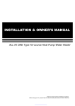
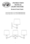
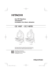
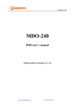
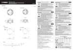
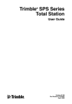
TEF 2650/2655
COMMANDER SEARCHLIGHT HALOGEN & HRI
INSTALLATION AND USER MANUAL
IMPORTANT
TUM 1094
REV. F. 12.11.2015
Please read this manual carefully before installing the
product.
Tranberg AS | P.O. Box 8033 | N-4068 Stavanger | Norway | Tel.: (47)51 57 89 00 | Fax.: (47)51 57 89 50
E-mail: [email protected] | www.tranberg.com
Tranberg Systems | Hjulmagervej 15C | 7100 Vejle | Denmark | Tel.: (45) 75 85 83 80
E-mail: [email protected] | www.tranbergsystems.com
COMMANDER SEARCHLIGHT - INSTALLATION AND USER MANUAL
SAFETY INSTRUCTIONS
•
The intense light output may damage eyes when
stared directly into the light.
•
Never use force to move the searchlight head on a motorized unit. This may damage the power train inside the
motor unit.
•
Never open a searchlight head while energized. High
voltage is present.
•
Always wait until light source and other components
have cooled before touching any part.
•
•
Any type of light source reaches a very high temperature. Do not touch if warm. Never touch with bare
skin as this reduces light output.
•
The motorized searchlight moves both vertically and
horizontally. Be aware of any personnel close to the
searchlight when testing or operating.
GENERAL WARRANTY CERTIFICATE
Tranberg AS gives normally a general warranty on Tranberg products valid for 12 months from delivery date.
General the products will
(a)
Confirm to the purchase order,
(b)
Be free from liens, claims and encumbrances,
(c)
Be free from failures or defects which may arise from defective design,
materials or workmanship.
The warranty is based on that “The assembly- and maintenance instruction”,
attached with the product, is fulfilled, and does not cover damage caused by misuse
or lack of proper maintenance and care.
Regards terms of delivery:
Other agreements than standard terms of delivery are to be in writing.
Official terms of delivery, NL-01 are valid.
Regarding the bulb, please look at the warranty papers following the bulb. This must be filled in and returned with the
bulb to Tranberg AS.
Page 2
COMMANDER SEARCHLIGHT - INSTALLATION AND USER MANUAL
TABLE OF CONTENTSNTS:
CONTENTS
1.
SYSTEM OVERVIEW
4
2.
OPERATION
5
3
MAINTENANCE
7
4
INSTALLATION
7
5
SPECIAL PROCEDURES
8
6
FAULT FINDING
7 CONNECTIONS, SETTINGS AND INDICATORS
8
10
TECHNICAL DATA
11
14
DRAWINGS16
600A101119 - TEF 2650 HALOGEN ASSEMBLY DRAWING
16
600A101119 - PART LIST FOR ASSEMBLY DRAWING
17
600A101119 - PART LIST FOR ASSEMBLY DRAWING
18
600A103633 - LAMP HOUSING TEF 2650 HALOGEN
19
600A103633 - PART LIST FOR LAMP HOUSING
20
600A102892 - DIMENSIONS FOR TEF 2640/ 2650 2000W / 3000W
21
600A102448 - DIMENSIONS - TEF 2640/ 2650 SEARCHLIGHT, 2000W 22
600A102893 - DIMENSIONS - TEF 2640/ 2650 SEARCHLIGHT, 250/1000W
23
600A106002 - DIMENSIONS - TEF 2655 SEARCHLIGHT, 250W / 1000W
24
600A104858 - JUNCTION BOX TEF 2650 HALOGEN
25
600A104860 - JUNCTION BOX TEF 2650/ 2655 HALOGEN 24 VDC
26
600A102101 - CONTROL PANELS DIMENSIONS AND CUT-OUTS
27
600A105539 - SYSTEM EXAMPLE, WIRING DIAGRAM
28
600A104949 - SEARCHLIGHT MAIN JUNCTION BOX, WIRING DIAGRAM
29
600A104881 - SEARCHLIGHT HEAD 1000/2000/3000W, WIRING DIAGRAM
30
600A105612- SEARCHLIGHT MAIN JUNCTION BOX, WIRING DIAGRAM
31
600A105641- REACTOR ENCLOSURE FOR HRI, GA AND WIRING DRAWING
32
600A105720 - GA DRAWING OF JUNCTION BOX FOR SEARCHLIGHT HRI
33
600A105721 - WIRING DIAGRAM FOR SEARCHLIGHT HRI, MAIN JUNCTON BOX 34
600A105722 - WIRING DIAGRAM FOR TEF 2650 HRI, SEARCHLIGHT HEAD
35
Page 3
COMMANDER SEARCHLIGHT - INSTALLATION AND USER MANUAL
1.
SYSTEM OVERVIEW
MULTI SEARCHLIGHT CONTROL PANEL TEF 2613
1
2
5
3
6
4
7
2
5
3
6
4
7
MULTI SEARCHLIGHT CONTROL PANEL TEF 2613
MULTI SEARCHLIGHT CONTROL PANEL TEF 2613
MULTI SEARCHLIGHT CONTROL PANEL TEF 2613
1
8
1
8
2
5
3
6
4
7
1
8
2
5
3
6
4
7
3 7
MULTI SEARCHLIGHT CONTROL PANEL TEF 2613
1
8
4 8
2
5
3
6
4
7
8
1 5
2 6
1 5
2 6
1 5
2 6
1 5
2 6
1 5
2 6
LIGHT
NARROW
FAST
LIGHT
NARROW
FAST
LIGHT
NARROW
FAST
LIGHT
NARROW
FAST
LIGHT
NARROW
IGNITION
WIDE
SLOW
IGNITION
WIDE
SLOW
IGNITION
WIDE
SLOW
IGNITION
WIDE
SLOW
IGNITION
WIDE
SLOW
DIM
HOME/
GROUP
ON/STBY
DIM
HOME/
GROUP
ON/STBY
DIM
HOME/
GROUP
ON/STBY
DIM
HOME/
GROUP
ON/STBY
DIM
HOME/
GROUP
ON/STBY
3 7
4 8
3 7
4 8
3 7
4 8
3 7
4 8
FAST
600A105424
The Tranberg Commander Searchlight uses a serial communication network to control and monitor the searchlights. This makes it possible to
freeely choose and combine the number of searchlights and panels. All
panels can control all searchlights, one at a time, by using selection buttons on the panel.
The communication network is connected as a bus topology, i.e. the communication cable is connected from unit to unit as a chain. In that way,
all units can communicate with every other unit, and can listen to every
message sent over the network. Each unit connected to a bus must be
uniquely identified by a number (address). This address is set either by
thumbwheels, or programmed and stored in internal non-volatile memory.
One of the units has to control the communication on the bus. The
unit performing this function is called a master, and in the Commander
Searchlight system this function is assigned to the panel with address ‘0’.
When the master is powered up it will check what units are present on the
bus by querying each unit. If one unit is not powered up in this phase, and
thus does not answer the query, it will be regarded as not-present and will
not be able to communicate with the other units on the bus. It is therefore
important that all searchlights are powered up before the panels.
Page 4
SEARCHLIGHT MOTION CONTROL:
The Commander Searchlights are equipped with positional sensors for both
motors/axes. This makes it possible to let the searchlight automatically move
to pre-defined positions, and also results in a smooth, controlled motion.
The searchlights can rotate more than one full revolution, approx. 370°, and
the end stop is located at the connection box. The vertical movement is from
approx. 15° upwards to approx. 35° downwards.
TYPES OF SEARCHLIGHTS / LIGHT SOURCES:
Available light sources:
•
Halogen has a wider, long range beam. Warm-white colour. Is powered directly by 230VAC.
•
Xenon has a narrow, extra long range beam. Daylight colour, part of the spectrum is ultraviolet (UV) making it useful for seeing ice (visual ice detection). Needs a separate power supply and
cabling.
•
HRI (metal-halide) has a high light output with daylight colour, re
sembling a xenon light. Has some restrictions regarding power on/off timing (reach full light output after 1 – 2 minutes on-time). Needs a separate ballast between 230VAC and lamp.
COMMANDER SEARCHLIGHT - INSTALLATION AND USER MANUAL
2.
OPERATION
2.1 START-UP PROCEDURE
If, for some reason, this is not possible, please do a manual re-scan as
described in chapter 5.2 after all units are powered up.
Power-up: Apply power in the following sequence:
1.
Apply the 230 VAC power to the searchlights first.
2.
Apply the 24 VDC power to the panels next. If the panels have
several separate supplies, ensure that the master panel is powered up last. The panels will be in the ‘on’ mode when powered
up.
2.2 CONTROL PANEL
A searchlight will do a position reference search when powered up and
receiving a bus query message from the master panel (a bus re-scan).
It will slowly turn to the right and tilt upwards until the end positions is
reached. The searchlight will not respond to joystick commands from
a panel until it has finished this position search phase (but the light can
be turned on and off).
3
7
MULTI SEARCHLIGHT CONTROL PANEL TEF 2613
1
4
2
5
3
6
1 5
2 6
LIGHT
NARROW
4
7
8
3 7
4 8
FAST
5
9
IGNITION
WIDE
SLOW
ON/STBY
DIM
HOME/
GROUP
1
10
600A102101
2
GENERAL
Any user can control any searchlight at any time. When the lamp on
a searchlight is turned on, it will be indicated in all the other panels
by the indicator for that searchlight (In the select buttons) flashing
slowly. If the same search¬light is selected from another panel (the
select button is pressed), then the other panel gains control over that
searchlight, and the first panel will loose its control. As this happens
the searchlight will maintain the previous lamp on or off setting, but
the speed setting will be dependent on the setting of the new control
panel.
When the control panel is turned off, the searchlights last operated
from this panel will automatically be turned off.
NOTE: Slow flashing is 1 sec on, 1 sec off. Fast flashing is 2 flashes
per second.
1.
“ON/STBY” or “POWER” (2612 / 2613 / 2614)
On / Standby button, activates the panel. The backlight will turn
on. Press momentarily to turn on, press and hold for 1 sec to go to
standby. In standby the panel will turn off all searchlights that was
used by that panel. The yellow indicator will light steady if it is a master panel, or flash slowly if it is a slave panel.
8
6
2.
“DIM” (2612 / 2613 / 2614)
Adjusts the panel backlight level. Press shortly yo change level one step,
press and hold to change the level to min or max.
3.
SEARCHLIGHT SELECT BUTTONS
2613: To select which searchlight you want to operate, press the buttons on the top row. The first is used to select searchlight no. 1 and 5.
The first press selects searchlight no. 1, press once more (within a second) to select searchlight no. 5. For the three other buttons works the
same way. It is only possible to select searchlights that are connected. The
panel may operate up to 8 searchlights and the system will automatically
detect the number and adresses of the searchlights that are connected.
2614: To select which searchlight you want to operate, press the buttons on the top row. The first (‘A’) is used to select searchlight no. 1.
The first press selects the first lightsource of searchlight no. 1, press
once more (within a second) to select the second lightsource. For the
three other buttons it works the same way. It is only possible to select
searchlights that are connected. The panel may operate up to 4 searchlights (addresses 1 to 4) and the system will automatically
detect the number and adresses of the searchlights that are connected.
Page 5
COMMANDER SEARCHLIGHT - INSTALLATION AND USER MANUAL
2
OPERATION
4.
10.
“LIGHT” (2612/2613/2614)
Turn light on or off. A green indicator light will light steady if the lamp
is on. Flashes rapidly when the group function is activated.
5.
“IGNITION” (2612/2613/2614)
Press to ignite the xenon lamp. Activates the ignitor as long as the
button is held. Not used for other lamp types. The searchlight will
automatically release the ignition relay after 10 seconds to save the
xenon lamp from excessive wear.
6.
“NARROW” AND “WIDE” (2612/2613/2614)
Adjusts the lamp focus. Will change the beam from wide to narrow or
backwards. Applicable only for searchlights with motor focus. Press
and hold to change focus. The focus motor will automatically stop at
each end position.
7.
HOME: Move to “home”
If only one searchlight is selected (or has been used from a panel), a
short press on this button will command the searchlight to go to its
(preset) home-position. A long press (> 5s) will set the searchlight’s
current position as the new home position for that searchlight.
GROUP: Move several searchlights
If two or more searchlights have been turned on from the same panel,
a short press on this button will start the group-function. The selected
searchlights will then move simultaneously.
INDICATOR TEST:
1. To see if all indicators on the front of the panel are working, pro
ceed as follows:
2. Turn off panel with the ‘ON/STBY’ button.
POSITION INDICATORS (2612/2613/2614)
Arrow left and right:
Steady light: The searchlight is in the sector left or right for the home position.
Slow flashing: The searchlight is at the normal left or right end position.
Fast flashing: The searchlight has stopped due to mechanical
overload or at the end limit switches.
Square:
Steady light: The searchlight is at its horizontal home position.
Slow flashing: The searchlight is at its horizontal and vertical
home position.
Fast flashing: The panel has sent a ‘set home position’ com-
mand to the searchlight.
8.
“HOME / GROUP” (2612/2613/2614):
DUAL FUNCTION:
3. Press and hold the ‘ON/STBY’ button for at least 5 seconds.
4. While holding the ‘ON/STBY’ button, press (and release) the ‘DIM’ button shortly.
5. Release the ‘ON/STBY’ button. All indicators on the front of the panel will now flash rapidly.
6. If joystick or buttons are operated during this test, a corresponding
LED (s) will extingwish as long as the button is held.
7. Press (and release) shortly the ‘ON/STBY’ button to exit lamp test
mode and to turn on panel.
NOTE: Slow flashing is 1 sec. on, 1 sec. off. Fast flashing is 2 flashes
per second.
JOYSTICK (2612/2613/2614):
Left – right. Up for light downwards, down for light upwards.
9.
“FAST” AND “SLOW” (2612/2613/2614):
Adjust motor speed. 9 Steps, 5 Indications
Speed
1 slow
2, 3
4, 5, 6
7, 8
9 fast
Fast
Slow
MULTI SAR SEARCHLIGHT CONTROL PANEL TEF 2614
SINGLE SEARCHLIGHT CONTROL PANEL TEF 2612
A
B
C
D
LIGHT
NARROW
FAST
LIGHT
NARROW
FAST
IGNITION
WIDE
SLOW
IGNITION
WIDE
SLOW
ON/STBY
DIM
HOME/
GROUP
ON/STBY
DIM
HOME/
GROUP
!
WARNING! UV/IR LIGHT
600A102101
TEF 2612 Single searchlight control panel
Page 6
TEF 2614 SAR searchlight control panel
COMMANDER SEARCHLIGHT - INSTALLATION AND USER MANUAL
3
MAINTENANCE
4
INSTALLATION
3.1 CLEANING
4.1 MECHANICAL INSTALLATION
PANEL:
The control panel may be cleaned with a mild detergent on any parts.
SEARCHLIGHTS PHYSICAL PLACEMENT:
SEARCHLIGHT:
Keep the searchlight and lens clean. Use only water and soft cloth to
clean the searchlight. Clean the front glass / lens only when the light is
off and has cooled down. If necessary, clean the mirror using alcohol.
Ensure that all remains of the cleaning solvent are removed. Use only
a soft cloth to clean the mirror.
3.2 LUBRICATION
The lubrication point at the bottom of the U-pieces should be greased
every two years. Use grease which is resistant to temperatures down
to –50°C.
3.3 MECHANICAL
Check all external screws on the searchlight periodically and tighten if
needed.
Control that the lamphouse moves smoothly and with low friction both
horizontally and vertically. Do not overtighten the four bolts in which
the lamphouse is hinged, as this may hinder the movement of the
searchlight.
Remove build-up of ice on and around the searchlight. The motor unit
and the lamphouse optional have both an internally mounted heater to
avoid condensation, but it is not designed for de-icing the searchlight.
3.4 ELECTRICAL
SEARCHLIGHT: Clean and inspect the electrical connections to xenon
lamp periodically. A layer of oxidation can build up as a result of lamp
heating and cooling. Also inspect the other high current connections
for bad contacts and overheating.
Consider the end stop of the horizontal movement, the end stop is
placed at the connection box, i.e. when the light head is facing in the
same direction as the connection box. Also consider if there are sectors
which should not be illuminated.
4.2 ELECTRICAL INSTALLATION - CABLING
CABLING – COMMUNICATION NETWORK:
1. Use 2x twisted pair cable or 1x twisted pair + screen. Characteristic impedance: 100 – 250 ohms. Suitable cables types can be cables
made for Profibus, Interbus, Ethernet, Cat5, or similar.
2. The communication network must be connected as a bus topology, i.e. from point to point (unit to unit). No loops or star connections are allowed. ( See drawing 600A105539)
3. No end terminations are necessary.
4. Connect A to A, B to B and Ref to Ref. Ref is also called Sh on
some units.
5. The order of panels and searchlights along the bus can be freely
chosen. Tip: A drawing of the system showing the order and addresses of the units can be of great help if troubleshooting should be
necessary.
NOTE1:
Keep communication cables away from all power lines.
NOTE2:
Treat / regard Shield/Reference as a signal. It shall under no circumstance be connected to Ground or other Protective Earth potentials.
See technical data for details of communication interface.
Connections, communication cable
RJ-45
1
2
3
4
5
6
7
8
Signal: Pin:
3
A
6
B
4
Ref
5
Ref
RJ-45
A
Ref
Ref
B
Cable RS-485
Shield
TIA 568-A:
White/Orange
Orange
Blue
White/Blue
1
2
3
4
5
6
7
8
A
Ref
Ref
B
Shield
TIA 568-B:
White/Green
Green
Blue
White/Blue
Use twisted pair cable with screen.
Characteristic impedance:
100-250ohm
Pin 1,2,7,8: Not connected
600A105512
CABLING - SEARCHLIGHT MAINS (230VAC):
For halogen searchlights both power to the lamp as well as power to
the motor unit are supplied through the same cable. Dimension the
cable and fusing according to the wattage of the lamp. Note that halogen lamps have a large inrush current at power-up (due to low filament
resistance when cold), so a slow fuse with same rating, or a fuse with
a higher rating is recommended.
Page 7
COMMANDER SEARCHLIGHT - INSTALLATION AND USER MANUAL
4
INSTALLATION
4.3 ELECTRICAL INSTALLATION - SETTINGS
Address settings:
1. Each unit (searchlight or panel) must have its own unique address.
Panels and searchlights have separate address spaces, i.e. a
panel with setting ‘2’ does not interfere with a searchlight set to
address ‘2’.
2. The addressed units (panels and searchlights) can be placed freely
along the bus, they don’t have to be placed according to their address or in any special order.
5
SPECIAL PROCEDURES
5.1 IDENTIFYING THE MASTER PANEL
For the following special procedures, the master panel need to be
identified.
The master panel can be recognized by the yellow indicator in the
power button. When you turn off power by pressing this button, the
yellow indicator will be continuously lit in the master panel. It will blink
slowly (1 sec. on, 1 sec off) on a slave panel.
5.2 RE-SCAN OF NODES CONNECTED TO THE BUS
3. The address of searchlights are normally pre-set from factory. See
chapter “changing address on searchlight” if changes are needed.
The address can also be hardwired by the address-rotary switch in
the connection box.
If necessary, the master panel can do a bus scan when powered up
using the following procedure:
4.4 STARTUP OF SYSTEM
1. Turn off the master panel using the power button. Release the button. The backlight will turn off.
1. Check that all connections are correct and no short-circuits or
breaks. Check all 230VAC supply lines. Also check the 24VDC
supply to the panels and other control modules.
2. Press and hold the power button for at least 5 seconds.
2. Turn on power first to the searchlight motor units, then the xenon
power supplies, and at last the 24VDC supplies to the panels. If
the panels are powered from separate supplies, then first apply
power to the slave panels, then to the master panel. Check visually that each searchlight makes a positional scan right after the
master panel is powered up. The master panel should now find all
searchlights and panels, and be able to communicate with them.
3. Check movement and light on /off of all searchlights.
(Note: Do not operate or use any panels or searchlights during this
procedure. Ensure that all are powered up.)
3. While holding the power button, press and release the second select button (marked ‘2/6’ (2613) or ‘B’ (2614) ). (Repeat if necessary, until backlight turns on).
4. The panel backlight will now turn on, and it will start the scanning
of the bus (it takes a couple of seconds).
5. Release the power button.
6. When the scan process is finished, the panel will show which
searchlights are present on the bus by fast flashing the corresponding leds on the select buttons (upper row).
7. Turn on the panel by using the power button as usual.
8. Repeat the procedure if necessary.
5.3 ALTERNATIVE RE-SCAN PROCEDURE
FOR PANELS DELIVERED FROM APRIL 2009 AND ONWARDS:
If necessary, the master panel can do a bus scan when powered up
using the following procedure: A panel can do both this alternate
re-scan procedure as well as the previous procedure (ch. 5.1).
(Note: Do not operate or use any panels or searchlights during this
procedure. Ensure that all are powered up.)
1. Set all panels to standby (“turn off”) by using the on/stdby button.
The backlight will turn off. Locate the master panel (see ch. 3.2),
and turn it on again.
2. Press and hold both speed buttons (‘fast’ and ‘slow’) for at least
5 seconds.
3. On the 2613 and 2614 panels, the indicators in the ‘searchlight
select’ buttons will start flashing in sequence. On the 2612 panels,
the indicators in the speed buttons will flash in sequence. Release
the speed buttons.
4. The sequential flashing will last for a couple of seconds, as long as
the scanning of the bus is performed. When the flashing is finished,
the system is ready for use.
5. Repeat the procedure if necessary.
Page 8
COMMANDER SEARCHLIGHT - INSTALLATION AND USER MANUAL
5
SPECIAL PROCEDURES
5.4 RESET OF SEARCHLIGHTS
1. Remove power (230VAC) to the searchlight (motor unit), wait for
approx. 10 sec, and reconnect the power. (It is not necessary to
disconnect the xenon power supply). If several searchlights need
to be reset, repeat this for each searchlight before commencing
to step
2. Do a re-scan from the master panel. Alternatively, remove and reapply power (24VDC) to the panels, either all or at least the master
panel. The searchlight will now move to the right and upwards to
find the end positions, and back to center. If necessary, watch the
searchlight at this stage to verify the movement.
5.5 RECALIBRATE END LIMITS ON SEARCHLIGHTS
1. Open the searchlight junction box and set DIP-switch no. 1 to ON.
2. Remove power (230VAC) to the searchlight (motor unit), wait for
approx. 10 sec, and reconnect the power. (It is not necessary to
disconnect the xenon power supply). If several searchlights need
to be reset, repeat this for each searchlight before commencing
to step 3.
8. Push power button once to turn on the panel. Check if
the searchlight can be controlled on the new address. The
procedure can be repeated if necessary.
9. If more searchlights are to be changed, disconnect the power to
the current searchlight, and repeat the procedure from step 3.
FINALIZING:
10. IMPORTANT: Turn the rotary switch on the rear of the
master panel back to the initial (noted) setting.
11. Mount the master panel back in place, connect the power supply
to all the searchlights.
12. Do a re-scan of the bus, either by disconnecting and
reconnecting the power supply to the master panel, or by following the re-scan procedure described further up in this document.
Repeat if necessary.
3. Do a re-scan from the master panel. Alternatively, remove and reapply power (24VDC) to the panels, either all or at least the master
panel. The searchlight will now do a complete movement up – right
– left – center/down to find the end limit positions, and back to
center. If necessary, watch the searchlight at this stage to verify
the movement.
4. Set the DIP-switch no. 1 back to OFF and close the junction box.
5.6 CHANGING ADDRESS ON A SEARCHLIGHT
PREPARATION:
1. Identify the master panel. Unmount the master panel, so as to get access to the rotary swiches on the rear.
IMPORTANT: Make a note of the settings of the switches
2. Disconnect the power supply to all the searchlights. (Leave the
power supply to the panels connected).
PROCEDURE:
3. Connect the power supply
address shall be changed.
to
the
searchlight
whose
4. Turn off the master panel using the power button. Release the button. The backlight will turn off.
5. Set the rotary switch labeled ”N/A” on the rear, set it to
one lower than the new address of the searchlight (address
minus 1, e.g. set to ‘1’ if the searchlight is to be set to
address ‘2’, i.e. respond to the first press of button ‘2/6’).
6. Press and hold the power button for at least 5 seconds. While
holding the power button, push the button marked ”3/7” (a short
normal push and release). This button can alternatively be pushed
several times, until the panel backlight is lit. When the backligth
is lit, release the power button. The panel will now send a special
message to the searchlight.
7. Check the indicators in the searchlight select buttons (”1/5”, ”2/6”,
”3/7” and ”4/8”). After approx. 5 – 10 sec. one of them will flash
fast (2 times pr. sec) to show the new address of the searchlight.
Page 9
COMMANDER SEARCHLIGHT - INSTALLATION AND USER MANUAL
6
FAULT FINDING
6.1 GENERAL
6.5 PROBLEMS AT INSTALLATION
1. Check which searchlights and from which panels the problem
exists on. Can the fault be isolated to a particular searchlight or
panel?
1. Check correct wiring (A is always connected to A, likewise for B
and Ref. No grounding of Ref or connected to protective earth).
Tip: if one unit in the middle of the comm. network bus does not
respond, it may be that A and B are swapped both for the incoming and the outgoing cable.
2. If it is a system with a radio control module (RCM), check if the
same problems exists with the ordinary (wired) panels.
3. When changing a setting/address on a unit, remove and reapply
power to let the change become operative.
2. Jerky movement (and/or light goes uncontrolled on/off) can be
caused by electrical noise on the network. Check correct wiring,
especially mix-up of Ref and A or B.
6.2 PROBLEMS WITH MOVEMENT
3. Two or several searchlights move simultaneously when only one is
selected from the panel: Check the addresses of the searchlights
(same address on two units).
1. No movement: Check if light is able to turn on/off: do a re-scan on
the master panel (see ch. 5.2 or 5.3).
2. Limited or shifted range of movement: possible problems with end
limit switches. Try resetting the searchlight (see ch. 5.4).
3. The searchlight moves with low speed only (And incorrect position
indication on panel): Possible problems with position sensors. Try
resetting the searchlight (ch. 5.4) or a recalibration of end limits
(ch. 5.5).
4. Spurious movement when joystick or panel is not operated: Possible electrical noise or interference on the communication network.
Check if this happens under special operation conditions of the
ship or other equipment. Alternatively, try resetting the searchlight
(ch. 5.4)
5. Not able to select a searchlight from any of the panels. Possible
failure of power supply or power dip (230VAC) to the searchlight.
Do a a re-scan on the master panel (see ch. 5.2 or 5.3).
6.3 PROBLEMS TURNING ON OR OFF THE LAMP
1. Check if movement functions normally. If yes, then the communication with the searchlight is OK and the fault may be in the lamp
circuits: Check the lamp itself, electrical wiring and relays. If no,
first try to reestablish the communication with the searchlight: Do
a re-scan on the master panel (see ch. 5.2 or 5.3).
2. Check if green indicator in “light” button functions normally (toggles on/off when pushing the button). If yes, then the communication with the searchlight is OK and the fault may be in the lamp
circuits: Check the lamp itself, electrical wiring and relays. If no,
the communication network may be faulty or being influenced by
interference, or the searchlight may have a power loss (230VAC).
Try to reestablish the communication with the searchlight: Do a rescan on the master panel (see ch. 5.2 or 5.3).
3. Check relay in the lamp power supply circuit: Contactor in junction
box, relay on motor drive electronics.
6.4 PROBLEMS WITH PANELS
1. A master panel is required to get the system to function. If the
panel set to master is faulty, the system will not function. Change
address on one of the other (slave) panels to ‘0’, remove and
reapply power (to the panel), and the panel will function as master.
See also ch. 5.2 and 5.3 for re-scan from the master panel.
2. If a button or a joystick is faulty, do the indicator test described in
ch. 2.2.
Page 10
4. Not possible to select any searchlight, or strange behaviour of the
indicators on one or more panels. Check the addresses on the
panels, two or more set at the same address.
5. Master panel: There shall be one and only one panel set to master
(ADR = 0) in a system. If no panel is set as master, the system will
appear “dead”, if more than one, the panels will have an unpredictable behaviour.
6. If several faults are present on a system, try to isolate one panel
and one searchlight and get this to work, then add more units step
by step.
7. To decide whether cabling or searchlight is erroneous, power a
panel (set to master) with a 9V battery and connect the communication network directly to a searchlight.
COMMANDER SEARCHLIGHT - INSTALLATION AND USER MANUAL
7 CONNECTIONS, SETTINGS AND INDICATORS
7.1 PANELS
CONNECTIONS
There are 3 different panel models:
Versions with phoenix screw terminals:
Connect ‘A/B’ to one pair and ‘Sh1/2’ to one pair. Alternatively: ‘A/B’
to one pair, screen to Sh1 or Sh2.
1. TEF 2612 Single (this panel can only control 1 searchlight, searchlight no. 1)
2. TEF 2613 Multi (the standard panel for control of up to 8 searchlights)
3. TEF 2614 SAR (Search And Rescue, can control 4 searchlights
with 2 light sources each)
All models are identical regarding outer dimensions and connections.
The 2613 and 2614 panels have 13 keys, while the 2612 panel has 9
keys (It does not have the upper 4 searchlight select keys).
Signal
Alt. 1
Alt. 2
A
Pair 1
Pair 1
B
Pair 1
Pair 1
Sh (Reference)
Pair 2
Screen
Sh (Reference)
Pair 2
Screen
Version with RJ-45 connectors
There are 2 versions of each of these panel models:
Pin
Color (TIA 568-A)
Color (TIA 568-B)
1. Old version with phoenix type screw terminals as bus connector
2. New version with RJ-45 connectors as bus connector
1
White / Green
White / Orange
N/C
2
Green
Orange
N/C
3
White / Orange
White / Green
4
Blue
Blue
Reference
5
White / Blue
White / Blue
Reference
6
Orange
Green
7
White / Brown
White / Brown
8
Brown
Brown
-
-
Comm. Port RS-485
600A104817
Made in Norway
N/A ADR.
50091314
Part No.: 2613381100
Fault
N/A
N/C
N/C
Shield
Settings
ADR
Address
Mode
0
0
0
Master
0
1-7
1-7
Slave
1
0-7
8 - 15
2
0
0
Master
2
1-7
1-7
Slave
3
0-7
8 - 15
4
0
0
Master
4
1-7
1-7
Slave
5
0-7
8 - 15
Panel Type
TEF 2613
TEF 2612
TEF 2614
For panels with RJ-45 connectors delivered before April 2009:
Rotary Switch
N/A
New version
B
24VDC
- + - +
Rx
Search Light
Operator Panel
Status
Tx Pwr.
Rotary Switch
24VDC
Old version (Delivered before April 2009)
A
SETTINGS
For all panels with phoenix screw terminals and panels with RJ-45
connectors delivered after April 2009:
Made in Norway
N/A ADR.
Comm. Port RS-485
Part No.:
2612341100
2613381100
Fault
Rx
50091314
- + - +
Status
Tx Pwr.
Search Light
Operator Panel
Shield
Signal
600A102101
Settings
ADR
Address
Mode
Panel Type
TEF 2613
0
0
0
Master
0
1-9
1-9
Slave
2
0
0
Master
2
1-9
1-9
Slave
4
0
0
Master
4
1-9
1-9
Slave
TEF 2612
TEF 2614
Note: The addresses 10 – 15 are not available on these panels.
Page 11
COMMANDER SEARCHLIGHT - INSTALLATION AND USER MANUAL
7 CONNECTIONS, SETTINGS AND INDICATORS
INDICATORS
Priority
Power btn LED
Fault LED
Description
1
Fast flash
Fast
Power on or off. Network error: No messages received.
2
Fast flash
Slow
Power on or off. Network error: The module receives messages on the bus, but none to
its own address.
-
Steady on
Off
Power off/standby, Master Panel
-
Slow flash
Off
Power off/standby, Slave Panel (Receives messages from master)
-
Off
Off
Power on, Master or Slave Panel
If a master panel do not get any answers/messages from any other slave or node, then the master will signal ‘No messages received’.
Slow flash: 1 sec. on, 1 sec off
Fast flash: 2 blink per second.
The yellow Rx and Tx LEDs shows the activity on the bus, and will flicker at normal bus activity.
The green Power LED will light steady when 24VDC is applied / supplied.
7.2 SEARCHLIGHT MOTOR UNIT
MODE
There are 2 different versions of the motor unit:
1. Version 1 with internal electronics: Connections are on numbered
screw terminals (See connection diagrams). No visible indicators
or settings. Address setting is done via bus programming. See
chapter 5.6 “Changing the address of a searchlight”. (Indicators
on the internal electronics board behave similarly to the indicators on the new version 2 electronics: Pwr –> Pwr, Rx –> Rx, I2
–> CPU).
ADR
Fault Pwr
CPU Rx
Sh B A Sh B A
Comm. Port RS-485
ON
123 4
Status
2. Version 2 (new) with electronics in the junction box
NOTE: The following chapters apply to version 2 (new) only.
CONNECTIONS
Signal
6
A
5
B
4
Sh
3
A
2
B
1
Sh
Comment
Reference
Reference
Made in Norway
MODE
Mode
ADR
ON
Fault Pwr
123 4
CPU Rx
Sh B A Sh B A
Comm. Port RS-485
L L L L
N N N N
Pin
Status
DIP switch
Description
1
If set to one: Do a full positional re-scan at next
power-up/bus query (deletes and replaces the previous
memorized endpositions).
2-4
Not in use
Searchlight
50091335
Rotary switch
Address
Description
0
Use the programmed address. To change see chapter
“Changing address on a searchlight”.
1-9
Set address equal to number. 1 = 1 (A) on panel, 2 = 2
(B) on panel, etc.
600A104858
For safety reasons the motors in the searchlight will stop after 1.5
seconds without communication on the bus.
Page 12
COMMANDER SEARCHLIGHT - INSTALLATION AND USER MANUAL
7
CONNECTIONS, SETTINGS AND INDICATORS
INDICATORS:
Rx (Yellow): shows the activity on the bus, and will flicker at normal
bus activity
Pwr (Green): light steady when the internal 24VDC is OK.
CPU (Green):
Priority CPU LED
Description
1
Steady on Is on for 5 sec. when power is applied
2
Fast flash
All OK and receiving messages from the bus
master
3
Slow
flash
OK, but not receiving messages to itself from
the bus
-
Off
Fault (Red)
Priority Fault LED
1
Description
Steady on 1.
Output stage of drive electronics has an
overtemperature condition
2.
During positional scan at power-up. If
one of the conditions for fast or slow
blinking occur at this phase, it will start
blinking correspondingly.
2
Fast flash
Overcurrent/overload at one or both motors.
Will continue to blink fast until both motors are
driven at the same time.
3
Slow flash
Not receiving any messages to itself. Delayed
5 sec. after the CPU LED.
-
Off
Normal condition
7.3 CONTROL MODULES
SIM and RCM module:
Priority Fault LED
Description
1
Steady on
Functional error: Can be several causes.
2
Fast flash
Network error: No messages received.
3
Slow flash
Network error: The module receives messages
on the bus, but none to its own address.
-
Off
Module and outputs OK.
Page 13
COMMANDER SEARCHLIGHT - INSTALLATION AND USER MANUAL
8
TECHNICAL DATA
SEARCHLIGHT
Model:
2650/ 2655
Halogen
250W (Ø355)
2650/ 2655
Halogen
1000W (Ø355)
2650 Halogen
1000W (Ø510)
2650 Halogen
2000W (Ø510)
2650 HRI
1000W (Ø410)
890 mm
890 mm
1084 mm
1084 mm
959 mm
Dimensions:
Height:
Width:
450 mm
450 mm
450 mm
450 mm
497 mm
Height w/pedestal:
1490 mm
1490 mm
1684 mm
1684 mm
1559 mm
Weight searchlight:
56 kg
56 kg
56 kg
56 kg
56 kg
Electrical:
Line input voltage (*):
230 VAC 202-254 VAC
Line input current (max):
3A
Standard cable gland dia.:
2 pcs. E204/2A/M20 6.4 – 11.8mm Ø
Comm. interface:
RS-485, Galvanically isolated
Required cable impedance:
typ. 100 – 250Ω
Optical system:
Lamp power:
Working voltage ( other voltage on request ):
Lamp lifetime (approx.):
Luminous flux:
Divergence:
Range at 1 lux ( theoretical calculation ):
Reflector diameter:
Focal point distance:
Tranberg Lamp Part No.:
250W
1000W
1000W
2000W
1000W
24V
230V
230V
230V
230V
300h
900h
900h
480h
12000h
12600 lm
21000 lm
21000 lm
50000 lm
90000 lm
6°
11°
7,9°
10,8°
2° - 7°
1320 m
1540 m
2043 m
2366 m
2000 m
Ø304 mm ( 12” )
Ø304 mm (12”)
Ø457 mm ( 18” )
Ø457 mm ( 18” )
Ø355 (14”)
69 mm (2 3/4”)
69 mm (2 3/4”)
127 mm ( 5”)
127 mm ( 5”)
69 mm (2 3/4”)
9400 037
9400 072
9400 072
9400 073
9400 100
Motion (motor unit):
Vertical range (positive = up):
Vertical speed:
Horizontal range (positive = right):
Horizontal speed:
50° (+15° - –35°)
0.7° - 11° per sec.
370° (±185°)
2° - 40° per sec
Materials:
Lamphouse and motor unit:
Stainless steel
Base:
Stainless steel
Lens:
Toughened soda-lime glass
Mirror:
Silver plated glass reflector
Fork and lifting rod:
Screw joint material:
Surface treatment:
Ingress protection (DIN40050):
Operating temperature:
(*) Other voltages available on request
Page 14
Stainless steel
Stainless steel
Powder coated RAL 9010
IP56
– 50°C - + 50°C
COMMANDER SEARCHLIGHT - INSTALLATION AND USER MANUAL
8
TECHNICAL DATA
PANEL:
Model:
2612, 2613, 2614
Length:
163 mm
Width.
96 mm
Height:
Height w/joystick:
62 mm
105 mm
Weight:
360 g
Mounting:
Flush
Input voltage:
12 – 28 VDC
Input current (at 24V):
max 120mA
Ingress protection (DIN40050):
Operating temperature:
Storage temperature:
IP20
0°C - + 40°C
– 20°C - + 60°C
Page 15
COMMANDER SEARCHLIGHT - INSTALLATION AND USER MANUAL
DRAWINGS
600A101119 - TEF 2650 HALOGEN ASSEMBLY DRAWING
Page 16
COMMANDER SEARCHLIGHT - INSTALLATION AND USER MANUAL
600A101119 - PART LIST FOR ASSEMBLY DRAWING
Page 17
COMMANDER SEARCHLIGHT - INSTALLATION AND USER MANUAL
600A101119 - PART LIST FOR ASSEMBLY DRAWING
Page 18
COMMANDER SEARCHLIGHT - INSTALLATION AND USER MANUAL
600A103633 - LAMP HOUSING TEF 2650 HALOGEN
Page 19
COMMANDER SEARCHLIGHT - INSTALLATION AND USER MANUAL
600A103633 - PART LIST FOR LAMP HOUSING
Ø
Ø
Page 20
COMMANDER SEARCHLIGHT - INSTALLATION AND USER MANUAL
600A102892 - DIMENSIONS FOR TEF 2640/ 2650 2000W / 3000W
Page 21
COMMANDER SEARCHLIGHT - INSTALLATION AND USER MANUAL
600A102448 - DIMENSIONS - TEF 2640/ 2650 SEARCHLIGHT, 2000W
Page 22
COMMANDER SEARCHLIGHT - INSTALLATION AND USER MANUAL
600A102893 - DIMENSIONS - TEF 2640/ 2650 SEARCHLIGHT, 250/1000W
Page 23
COMMANDER SEARCHLIGHT - INSTALLATION AND USER MANUAL
600A106002 - DIMENSIONS - TEF 2655 SEARCHLIGHT, 250W / 1000W
Page 24
COMMANDER SEARCHLIGHT - INSTALLATION AND USER MANUAL
600A104858 - JUNCTION BOX TEF 2650 HALOGEN
Page 25
COMMANDER SEARCHLIGHT - INSTALLATION AND USER MANUAL
600A104860 - JUNCTION BOX TEF 2650/ 2655 HALOGEN 24 VDC
Page 26
COMMANDER SEARCHLIGHT - INSTALLATION AND USER MANUAL
600A102101 - CONTROL PANELS DIMENSIONS AND CUT-OUTS
Page 27
COMMANDER SEARCHLIGHT - INSTALLATION AND USER MANUAL
600A105539 - SYSTEM EXAMPLE, WIRING DIAGRAM
Page 28
COMMANDER SEARCHLIGHT - INSTALLATION AND USER MANUAL
600A104949 - SEARCHLIGHT MAIN JUNCTION BOX, WIRING DIAGRAM
Page 29
COMMANDER SEARCHLIGHT - INSTALLATION AND USER MANUAL
600A104881 - SEARCHLIGHT HEAD 1000/2000/3000W, WIRING DIAGRAM
Page 30
COMMANDER SEARCHLIGHT - INSTALLATION AND USER MANUAL
600A105612- SEARCHLIGHT MAIN JUNCTION BOX, WIRING DIAGRAM
Page 31
COMMANDER SEARCHLIGHT - INSTALLATION AND USER MANUAL
600A105641- REACTOR ENCLOSURE FOR HRI, GA AND WIRING DRAWING
Page 32
COMMANDER SEARCHLIGHT - INSTALLATION AND USER MANUAL
600A105720 - GA DRAWING OF JUNCTION BOX FOR SEARCHLIGHT HRI
Page 33
COMMANDER SEARCHLIGHT - INSTALLATION AND USER MANUAL
600A105721 - WIRING DIAGRAM FOR SEARCHLIGHT HRI, MAIN JUNCTON BOX
Page 34
COMMANDER SEARCHLIGHT - INSTALLATION AND USER MANUAL
600A105722 - WIRING DIAGRAM FOR TEF 2650 HRI, SEARCHLIGHT HEAD
Page 35
COMMANDER SEARCHLIGHT - INSTALLATION AND USER MANUAL
Tranberg AS | P.O. Box 8033 | N-4068 Stavanger | Norway | Tel.: (47)51 57 89 00 | Fax.: (47)51 57 89 50
E-mail: [email protected] | www.tranberg.com
Tranberg Systems | Hjulmagervej 15C | 7100 Vejle | Denmark | Tel.: (45) 75 85 83 80
E-mail: [email protected] | www.tranbergsystems.com
Page 36