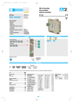
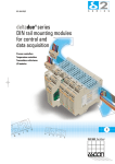
1
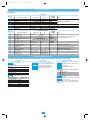
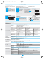
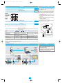
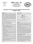
D9ed2-FE-uso
20-01-2006
14:58
Pagina 6
DIN rail mounting
2 channels data
acquisition module
E
ASCON spa
D9 line
E
R
I
E
S
c
D9 line
ISO 9 0 0 1
User manual
S
Installation manual • M.U. D9-2/06.01 • Cod. J30-478-1AD9 FE
C e r t i f i e d
C
UL
US
LISTED
Table of contents
- Resources
- Operating modes
- Model code
- Table and description of standard
parameters
- Technical specifications
- Commands
- Communications parameters reset
- Serial communications connection
example
- Warranty
ASCON spa
Via Falzarego 9/11
20021 Bollate
(Milano) Italy
Tel. +39 02 333 371
Fax +39 02 350 4243
http://www.ascon.it
e-mail [email protected]
Operating modes
Resources
Operating mode
Main universal inputs
Digital outputs [1]
OP1
PV1
12
PV1 1 Acquisition
OP1 OP2 OP3 OP4
PV2 2 Acquisition
PV2
12
Alarms
OP2
PV1 3 Acquisition
Digital inputs [2]
Digital input for external commands
OP3
IL1
OP1 OP2 OP3
PV2 4 Acquisition
PV1 5 Acquisition
OP4
OP1 OP2
PV2 6 Acquisition
OP3 OP4
OP4
D9
IL1 connected functions
Available functions
Not
Notes:1. Each output (OP1...OP4) can freely be associated with one of the two inputs (PV1 or PV2).
2. When outputs OP3 and OP4 are not used as such, they can be used as voltage free or voltage digital inputs.
Modbus RS485
Parameterisation Supervision
Model code
Configuration
Mod.
D 9
Line
The product code indicates the specific hardware coniguration of
the instrument, that can be modified by specialized engineers only
5 B C 0 - 0 F 0 0 / I L M N - 0 0 0 0
Basic
Accessories
2nd
part
part
D 9
Line
Output OP1-OP2
Relay - Relay
Relay - SSR Drive
SSR Drive - SSR Drive
SSR - SSR
SSR - SSR Drive
Input type
Input type
TR Pt100 IEC751
TR Pt100 IEC751
TC L Fe-Const DIN43710
TC J Fe-Cu45% Ni IEC584
TC T Cu-CuNi
TC K Chromel -Alumel IEC584
TC S Pt10%Rh-Pt IEC584
TC R Pt13%Rh-Pt IEC584
TC B Pt30%Rh-Pt Pt6%Rh IEC584
TC N Nichrosil-Nisil IEC584
TC E Ni10%Cr-CuNi IEC584
TC Ni-NiMo 18%
TC W3%Re-W25%Re
TC W5%Re-W26%Re
0…50mV linear
10…50mV linear
mV “Custom” input range
1st
B
1
2
3
4
5
Range
Range
-99.9…300.0 °C
-200…600 °C
0…600
°C
0…600
°C
-200 …400 °C
0…1200
°C
0…1600
°C
0…1600
°C
0…1800
°C
0…1200
°C
0…600
°C
0…1100
°C
0…2000
°C
0…2000
°C
Engineering units
Engineering units
On request
Serial communications
CANbus
RS 485 Modbus/Jbus SLAVE
PV1
PV2
-99.9…572.0 °F
-328…1112 °F
32…1112 °F
32…1112 °F
-328…752 °F
32…2192 °F
32…2912 °F
32…2912 °F
32…3272 °F
32…2192 °F
32…1112 °F
32…2012 °F
32…3632 °F
32…3632 °F
I
M
0
0
0
0
0
0
0
0
0
0
1
1
1
1
1
1
1
C
3
5
L
N
0
1
2
3
4
5
6
7
8
9
0
1
2
3
4
5
6
1
User manual
Italian - English (std)
French - English
German - English
Spanish - English
F
0
1
2
3
D9ed2-FE-uso
20-01-2006
14:58
Pagina 7
Table of standard parameters
If not specified, each the parameter must be doubled: one set for LOOP1 and one set for LOOP2. If the parameter is unique (1 parameter for both the loops) it is pointed out in
the notes column
Configuration
Mnemonic
code
IL
Prot
baud
PStr
Unit
Sc.dd
Sc.Hi
Sc.Lo
Parameter descritption
Digital input function IL
Communication protocol
Baud rate
Instrument position
Engineering unit
N° of decimals
Low range
High range
Setting range
Unit
see table 1
M.bus/Jbus
1200, 2400, 4800, 9600 baud
Alone/left side/central/right side
see table 2
0...3
-999...9999
Engineering unit
-999...9999
Engineering unit
Alarms and auxiliary
Mnemonic
code
A1hy
A1SR
A1.tp
A1Lb
A1.O
t.Fil
In.Sh
Addr
Hi.PV
OP.lk
Ack
Nt.O1
RF.L
RF.H
RF
Parameter descritption
AL1 hysteresis
AL1 alarm source
AL1 alarm type
Latching/blocking alarm functions
AL1 output
Filter time constant
Input shift
Communications address
PV (measure) Hold
Output lock
Alarms acknowledge
Negate (NOT) OP1
RF low range
RF high range
Reference value
Setting range
Unit
0.1...10.0
% range
Loop 1/loop 2
See table 3
None/Ltch/Bloc/LtbL
Internal status/OP1/OP2/OP3/OP4
OFF/1...30
s
OFF/-60...+60
Digit
1...247
0/1
0/1
0/1
0/1
low range...RF. H
Engineering unit
RF. L...high range
Engineering unit
range
Engineering unit
Factory
setting
not used
M.bus
9600
Alone
none
0
Low range
High range
Factory
setting
0.5
Loop 1
Inhibited
None
Internal status
Inhibited
Inhibited
247
0
0
0
0
----------
Notes
Valid for both the channels
Linear scales only
Range min. 100 digit (linear scales only)
Notes
The same parameters are available also
for AL2, AL3 and AL4 alarms
Valid for both the channels
Locks the outputs OP1, OP2, OP3, OP4
Valid for both the channels
Available also for OP2 - OP3 - OP4
Standard parameters description
The parameters shown in the table are divided into groups which work in the same way. Below they will be described as they are listed in the table.
Configuration
IL
Digital input function - Table 1
Parameter decription
Not used
Loop 1 measure hold
Loop 2 measure hold
Hold both the measuring loops
Output locks
Alarms acknowledge
unit
Setpoint (SP)
A1S.P
A2S.P
A3S.P
A4S.P
AL1 - AL2 - AL3 - AL4 threshold
Alarm occurrences of AL1,AL2,AL3 and OP4.
The range of the alarm threshold
correspond to the whole span and it is not
limited by the SP Setpoint span.
Auxiliary parameters
A1.tp
A2.tp
A3.tp
A4.tp
Value
0
1
2
3
Alarm type
The parameter allows to specify how each
shoud function.
The types of alarm available are:
Action
Disable
Sensor/Loop Break
Absolute high
Absolute low
Engineering units - Table 2
Parameter description
°C (Centigrade degrees)
°F (Fahrenheit degrees)
None
mV (millivolt)
V (Volt)
mA (milliampere)
In.Sh
Input shift
This function shifts the whole PV scale of up to ±60 digits.
Parameter description
A (Ampere)
bar
psi
Rh
pH
Addr
Controller address
The address range is from 1 to 247 and must be unique
for each instrument on the communications bus to the
supervisor.
2
D9ed2-FE-uso
20-01-2006
14:58
Pagina 8
AL1 - AL2 - AL3 - Al4 Alarms
For each alarm is possible to configure:
A - Source
B - The type and the operating condition of the alarm
C - The functionality of the alarm acknowledgement
D - The blocking function on start-up
A - Source
C/D - Latching, blocking and acknowledge functions enable
AL1, AL2, AL3 and AL4 Alarm acknowledge function
A1L.b
latching and blocking
The alarm, once occurred, is maintained
A2L.b
For each alarm it is pos- until to the time of acknowledgement.
A3L.b
sible to select the fol- The acknowledge operation is performed
A4L.b
by serial communications.
lowing functions:
ack
Alarm source
Each alarm AL1, AL2, AL3 and AL4
can be freeely associated to one of
the two input channels.
The threshold is compared with the
Setpoint of the selected channel (SP).
A1Sr
A2Sr
A3Sr
A4Sr
E - Loop break or sensor break
F - Output linked to each alarm
After this operation, the alarm leaves
the alarm state only when the alarm
condition is no longer present.
- None
- Latching
- Blocking
- Both latching and blocking
Start-up disabling
Ramp down
∆SP
SP
On
Off
Disable
Start-up
Ramp up
SP
∆SP
Disable
On
Off
Start-up
∆SP Threshold = SP±range
B - Alarm type and function
A1tp
Absolute alarm
On
Active
Off
high
Active
low
A2tp
A3tp
On
Off
A4tp
hy
low range
alarm
threshold
high range
F - Alarm addressing
Physical Output linked to the alarm
A1.O
One or more alarms (OR function) can be
A2.O
linked to the physical outputs OP1...OP4.
A3.O
The parameter can assume the following
values: Internal status, OP1, OP2, OP3, OP4.
A4.O
Input digital filter
100%
63.2%
PV
0
t.Fil
Time
Time constant, in seconds,
of the RC input filter applied
to the PV input.
When set to “inhibited”
the filter is bypassed.
Technical specifications
Features
Description
(at 25°C T. env.)
Total configurability
PV1 and PV2 inputs
Digital input
Operating mode
OP1 - OP2 outputs
OP3 - OP4 outputs
Outputs functions
AL1 - AL2
AL3 - AL4
alarms
Serial communications
Operational safety
General characteristics
By means of the configuration tool it is possible to select: - type of input - type of output - type and functionality of the alarms
A/D converter with resolution of 50,000 points
Update measurement time: 0.2 s
Common
Sampling time: 0.5 s (max. measurement updating time)
characteristics
Input bias: -60…+60 digit
Input filter: 1…30 s (0 = OFF)
0.25% ±1 digit (for temperature sensor) Between 100…240Vac
Accuracy
0.1% ±1 digit (for mA and mV)
the error is minimal
Resistance thermometer
2 or 3 wires connection
Line: 20Ω max. (3 wires)
Pt100Ω at 0°C(IEC 751)
(for ∆Τ: R1+R2
Burnout (with any
Input drift: 0.35°C/10°C Env.Temp.
°C/°F selectable
must be <320Ω)
combination)
<0.35°C/10Ω Wire Res.
Internal cold junction
Line 150Ω max.
L, J, T, K, S, R, B, N, E, W3, W5 (IEC 584) compensation with NTC
Input drift:
Thermocouple
°C/°F selectable
Error 1...20°C ±0,5°C
<2µV/1°C Env. Temp.
Burnout
<5µV/10Ω Wire Res.
0/4…20mA,
2.5Ω
ext.
shunt
Burnout.
Engieering
inputs,
DC input (current)
Rj >10MΩ
decimal point position configurable Input drift:
10...50mV,
Low range: -999…9999
<0.1%/20°C Env. Temp.
DC input (voltage)
0...50mV
high range: -999…9999
<5µV/10Ω Wire Res.
Rj >10MΩ
(min. range: 100 digits)
Mutual isolation
Isolation voltage 500V
Closing the external
Measure hold, alarms acknowledge, outputs lock
contact allows:
2 acquisition channels with 1, 2, 3 or 4 alarms
SPST relay NO, 2A/250Vac (4A/120 Vac) for resistive load
SSR, 1A/250Vac for resistive load
SSR drive: 0/5Vdc, ±10% 30 mA max.
To meet the double isolation requirements, OP1 and OP2 must have the same load type
Non isolated logic: 0/5Vdc, ±10% 30 mA max.
For all the outputs the inversion function (NOT) is available
Hysteresis
0.1…10.0%
Active high
Action type Absolute threshold on the whole range
Active low
Action
Special
Sensor break, Loop break
functions
Alarm acknowledge (latching), activation inhibit (blocking)
Alarm source
Assignes the alarms to PV1 or PV2
Assignes the alarm condition to an output (OP1, OP2, OP3, OP4).
Alarm output
If not configured, the alarm status is available on the coil
RS 485 isolated, Modbus/Jbus protocol, 1,200, 2,400, 4,800, 9,600 bit/s 2 wires
Measure input
Detection of out of range, or input problems causes automatic activation of the safety strategies
Parameters
Parameters and configuration data are stored in a non volatile memory for an unlimited time
Outputs lock
Power supply (PTC protected) 24Vac (-25...+12%) 50/60Hz and 24Vdc (-15...+25%)
Power consumption 3 W max.
Safety
EN61010-1 (IEC1010-1), installation class 2 (2.5kV), pollution degree 2, instrument class II
Electromagnetic compatibility Compliance with the CE standards
UL and cUL Approval
File E176452
Protection
Terminal blocks: IP20
Dimensions
Pitch: 22.5 mm - height: 99 mm - depth: 114.5 mm - height: 53 mm
Weight
156 g approx.
3
D9ed2-FE-uso
20-01-2006
14:58
Pagina 5
Commands
Communications parameters reset
Alarms acknowledge
The serial communications parameters can be reset to
the original factory settings (protocol: Modbus, Baud
Rate: 9600, Address: 247).
The instructions to remove/re-insert the I/O module from/in
its plastic case are described in the “Installation manual”.
After having removed the module, use the instructions
that follow to reset the communications parameters:
1) Use a jumper to short-circuit the terminals shown in
the drawing that follows;
2) Insert the I/O module in its housing and power ON the
instrument;
3) Extract the I/O module from its plastic case and remove
the short circuit jumper;
4) Reinstall the module in its housing.
At the end to this procedure, the communications parameters will be reset to its factory settings.
Ack
The acknowledge operation is performed by serial communications.
Negate output status
Nt.0x
Is possible to enable, separately for each output (DO1... DO4), the negate (NOT) fuction of the output internal logic status.
On
Internal
logic status Off
Enable NOT On
function
Off
On
Off
Output
status
PV Measure Hold
Hl.PV
Through the digital input IL is possible to hold the value of the PV measure (PV1, PV2 or PV1 and PV2).
Outputs lock
OP.lk
Output ports can be switched to OFF through the serial communications port.
Relay
AOOutputs lock status is maintained if the module is powered OFF
µP
Relay
Digital input commands
Performed operation
Off
None
Hold PV1 measure
Hold PV2 measure
Hold PV1 and PV2 measures
Normal operation
Normal operation
Normal operation
Outputs status not
influenced
Outputs lock
Alarms acknowledge
Alarms active
Notes
On
T
Function
Not used
PV1 is hold
The value of PV (PV1 or/and PV2) is
PV2 is hold
“frozen” at the time the digital input
PV1 and PV2 are hold goes to the close state
digital IL command inhibits all the
Outputs in OFF status The
outputs at the same time
digital IL command acnowledges
Alarms acnowledged The
all the alarms active at the same time
In order to reset the serial communication
parameters to their default values, use a
junper to short-circuit the indicated
terminals
A function can be assigned, through the configuration procedure, to digital input. The configured function is activated when
the digital input (free voltage contact or open collector output) is in the ON status (closed). The function is reset to the normal operation by setting the input to the OFF status (open).
Activating the function through the digital input has the highest priority than the keypad or the serial communications command activation.
Warranty
Serial communications connection example
Configuration
D9
Configuration
Cd-Rom
1
5
2
6
3
7
4
8
RS485
D9
OP1
OP2
OP3
OP4
PWR
COM
9 10 11 12
13 14 15 16
For SCADA
Local control
PC with
Autolink
31 max. instruments
1
5
2
6
3
7
4
8
1
5
2
6
3
7
4
8
D2
D9
1
5
D2
2
6
3
7
4
8
1
5
2
6
3
7
4
8
D2
31 max. instruments
D9
1
5
2
6
3
7
4
8
D9
RS485
1
5
2
6
3
7
4
8
1
5
2
6
3
7
4
8
D2
D9
1
5
D2
2
6
3
7
4
8
1
5
2
6
3
7
4
8
D2
OP35
operator
panel
D9
1
5
2
6
3
7
OP1
OP1
OP1
OP2
OP2
OP2
OP2
OP3
OP3
OP4
OP4
PWR
COM
9 10 11 12
13 14 15 16
PWR
COM
9 10 11 12
13 14 15 16
9 10 11 12
9 10 11 12
13 14 15 16 13 14 15 16
9 10 11 12
13 14 15 16
OP3
OP3
OP4
OP4
PWR
COM
9 10 11 12
13 14 15 16
4
8
D9
OP1
PWR
COM
9 10 11 12
13 14 15 16
9 10 11 12
9 10 11 12
13 14 15 16 13 14 15 16
9 10 11 12
13 14 15 16
4
RS485
We warrant that the products will be free from
defects in material and workmanship for 3 years
from the date of delivery.
The warranty above shall not apply for any failure
caused by the use of the product not in line with
the instructions reported on this manual.