1
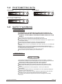
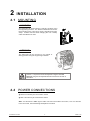
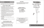
EXPOLITE TourLED 36 CW/WW
USER MANUAL
T
ABLE OF CONTENTS
PART 1 PRODUCT (GENERAL)....................................................1.
1.1--PRODUCT INTRODUCTION.........................................................1.
1.2--PRODUCT FEATURES.................................................................1.
1.3--TECHNICAL SPECIFICATIONS.....................................................2.
1.4--PHOTOMETRIC DATA..................................................................3.
1.5--SAFETY WARNING......................................................................3.
PART 2 INSTALLATION...............................................................4.
2.1--MOUNTING...................................................................................4.
2.2--POWER CONNECTION................................................................. 4.
2.3--SETTING UP WITH A DMX512 CONTROLLER.................................5.
2.3-1--DMX512 ADDRESSING WITHOUT ID ADDRESSING......................................5.
2.3-2--DMX512 ADDRESSING WITH ID ADDRESS..................................................5.
PART 3 DISPLAY PANEL OPERATION.........................................7.
3.1--BASIC..........................................................................................7.
3.2--MENU..........................................................................................7.
3.3--EDIT STATIC COLOUR.................................................................8.
3.4--DMX512 SETTINGS......................................................................8.
3.5--RUN MODE.................................................................................. 8.
3.6--PERSONALITY............................................................................ 8.
3.7--ID ADDRESS............................................................................... 9.
3.8--SPECIAL SETTINGS.................................................................... 9.
3.9--A CTIVATE THE PASSWORD ....................................................... 9.
3.10-- WHITES SETTING ..................................................................... 9.
PART 4 USING A DMX512 CONTROLLER....................................10.
4.1--BASIC ADDRESSING.................................................................10.
4.2--CHANNEL ASSIGNMENT............................................................10.
4.3--BASIC INSTRUCTIONS FOR DMX512 OPERATION......................12.
PART 5 APPENDIX......................................................................13.
5.1--TROUBLE SHOOTING............................................................... 13.
5.2--MAINTENANCE........................................................................ 14.
1
PRODUCT (GENERAL)
1.1
PRODUCT INTRODUCTION
This product is designed for indoor or outdoor use. Suitable applications include wash or
effect lighting for architectural, stage or nightclub applications. This product can also be
installed for use in signage and advertising using the dynamic functions available with
DMX512 control. Direct input of DMX512 signal allows the units to be controlled from any
DMX512 controller. This product can be operated as a single unit or in multiple units for
large applications.
1.2
PRODUCT FEATURES
LED FIXTURE
*
*
*
*
*
*
*
*
*
*
1 PRODUCT(GENERAL)
Dimmer 0-100%
Strobe
IP65 protection rating
LED display
Display control 'lock-out'
Direct DMX512 input
Independent ID address
'Over-heat' protection (showing HT )
Lightweight aluminium casing
Different white colors setting
1
2008.9.19
1.3
TECHNICAL SPECIFICATIONS
LED MODULE
LED MODULE:
Voltage
100~240V...50/60Hz
Rated Power
60W
IP65 protection rating
IP
36pcs (18 x Cool white / 18 x Warm white)
LED/Unit
Output/LED
1W
Environment Temperature -20
Cooling
Dimensions
243 x 200 x 245mm
Weight
1 PRODUCT(GENERAL)
~40
Direct air convection
4Kg
2
2008.9.19
PHOTOMETRIC DATA
COOL WHITE
WARM WHITE
847
388
226.8
149.4 LUX
3
2
1
0
1
2
3
15
3128
3
2
1
0
1
2
3
4
2
6
8
10Distance(m)
1781
466
216
128
2
4
6
8
87 LUX
15
1.4
10Distance(m)
COOL WHITE+WARM WHITE
1.5
4951
1320
602
350.7
2
4
6
8
236.7 LUX
15
3
2
1
0
1
2
3
10Distance(m)
SAFETY WARNING
IMPORTANT
ALWAYS READ THE USER MANUAL BEFORE OPERATION.
PLEASE CONFIRM THAT THE POWER SUPPLY STATED ON THE
PRODUCT IS THE SAME AS THE MAINS POWER SUPPLY IN YOUR
AREA.
This product must be installed by a qualified professional.
Always operate the equipment as described in the user manual.
A minimum distance of 0.5m must be maintained between the equipment and
combustible surface.
The product must always be placed in a well ventilated area.
Always make sure that the equipment is installed securely.
DO NOT stand close to the equipment and stare directly into the LED light
source.
Always disconnect the power supply before attempting and maintenance.
Always make sure that the supporting structure is solid and can support the
combined weight of the products.
The earth wire must always be connected to the ground.
Do not touch the power cables if your hands are wet.
ATTENTION
This product left the place of manufacture in perfect condition. In order to
maintain this condition and for safe operation, the user must always follow the
instructions and safety warnings described in this user manual.
Avoid shaking or strong impacts to any part of the equipment.
Make sure that all parts of the equipment are kept clean and free of dust.
Always make sure that the power connections are connected correct and
secure.
If there is any malfunction of the equipment, contact your distributor
immediately.
When transferring the product, it is advisable to use the original packaging in
which the product left the factory.
Shields, lenses or ultraviolet screens shall be changed if they have become
damaged to such an extent that their effectiveness is impaired.
The lamp (LED) shall be changed if it has become damaged or thermally
deformed.
1 PRODUCT(GENERAL)
3
2008.9.19
2
2.1
INSTALLATION
MOUNTING
HANGING
The LED PAR can be mounted in a hanging position using
the supporting bracket. The bracket should be secured to
the mounting truss or structure using a standard mounting
clamp. Please note that when hanging the unit a safety
cable should also be used.
UPRIGHT
The LED PAR can be mounted in an upright or
sitting position using the supporting brackets.
The LED MODULE can be mounted at any angle and in any
position. It is possible to further adjust the angle of the LED
MODULE using the two adjustment knobs located on the side of
the fixture.
2.2
POWER CONNECTIONS
@ 220V: 50 units may be connected in series
@120V: 25 units may be connected in series
Note: As this fixture's DMX signal cable connection is Parallel connection, so if over 20 units
to be connected, then a DMX signal amplifier is needed.
2 INSTALLATION
4
2008.9.19
2.3
SETTING UP WITH A DMX512
CONTROLLER
2.3-1 DMX512 ADDRESSING WITHOUT ID ADDRESSING
(STUDIO 2 MODE)
Connect the DMX512 controller to the units in series.
Each unit has 6 DMX channels so the DMX Addresses should increase by increments of
6 (e.g. 1,7,13,19...)
The ID address has not been set so therefore when using the controller CH8 must
be inactive ( CH6=0 ).
It is also possible to deactivate ID address selecting ID OFF from the Settings menu.
on the fixture
Each DMX Address may be used as many times as required.
Any DMX address in the range from 001 to 512 may be used.
Example:
DMX Addr.1
DMX Addr.7
DMX Addr.13
............
DMX512
CONTROLLER
The figure above shows a simple DMX512
layout with the starting address of the first
unit set at 1, with the second set at 7 and
so on... (Note that when used in this way,
the CH6 ID function must be inactive (CH6=0))
2.3-2 DMX512 ADDRESSING WITH ID ADDRESS (STUDIO 2 MODE)
Connect the DMX512 controller to the units in series
Each unit has 6 DMX channels so the DMX Addresses should increase by increments of
6 (e.g. 1,7,13,19...)
Each DMX Address may be used as many times as required.
Any DMX address in the range from 001 to 512 may be used.
Each DMX address may carry up to 66 separate ID addresses.
ID should be set in the menu on each unit in ascending values
(i.e. 1,2,3...)
ID On should be set in the Settings menu on each unit.
ID addresses are accessible from CH6 on the DMX512 controller.
2 INSTALLATION
5
2008.9.19
Example:
DMX Addr.1
ID Addr.1
DMX Addr.1
ID Addr.2
DMX Addr.1
ID Addr.3
DMX Addr.7
ID Addr.1
DMX Addr.7
ID Addr.2
DMX Addr.7
ID Addr.3
............
DMX512
CONTROLLER
2 INSTALLATION
The figure above shows a simple DMX layout
which has used three units at each DMX address.
The three units have different ID addresses which
allows the user to collectively control the whole
group of units at that DMX address by setting
CH6 to 0, or to control each unit independently by
first selecting the DMX address and then by using
Ch6 to locate the target ID address.
6
2008.9.19
3
DISPLAY PANEL OPERATION
3.1
BASIC
The LED fixture is mounted with a LCD display and 4 control buttons.
POWER IN
POWER OUT
DMX IN
DMX OUT
MENU
MENU
SET
UP
SET
UP
DOWN
DOWN
scroll through the main menu or return to the main menu
enter the currently selected menu or confirm the current function value
scroll 'UP' through the menu list or increase the value of the current function
scroll 'DOWN' through the menu list or decrease the value of the current function
3.2
MODE
MENU
S TA I
COOL
WARM
STRb
dIMM
dMX
d(001~512)
RUN
dMX
SLAV
PERS
CW
CWd
STU1
C.(0~255)
W.(0~255)
S.(0~20)
d.(0~255)
STU2
Id
I(001~066)
SET
UPLd
REST
IdON
PASS
ON
OFF
CALI
W1
W2
PASS
PASS
ON
OFF
SENd
REST
ENd
C.(0~255)
W.(0~255)
W8
3 DISPLAY PANEL OPERATION
7
2008.9.19
3.3
MODE
EDIT STATIC COLOUR
C.(0~255)
W.(0~255)
S.(0~20)
d.(0~255)
COOL
WARM
STRb
dIMM
S TA I
STATIC COLOUR
Combine COOL , WARM ,and Dimmer
color temperature
Set the value of the Strobe
(0-20Hz)
3.4
MODE
to create whites with different
DMX512 SETTINGS
d(001~512)
dMX
DMX
Enter the DMX
3.5
MODE
mode to set the DMX ADDRESS.
RUN MODE
RUN
dMX
SLAV
RUN MODE
Enter the RUN MODE mode to set working mode.
DMX mode is for using the DMX512 controller to control the fixtures.
SLAVE mode is for Master -- Slave operation, or controlled fixture by
Pix-controller.
Note: When fixtures are under Auto program operation, the
works.
3.6
MODE
RUN MODE
does no
PERSONALITY
PERS
CW
CWd
STU1
STU2
PERSONALITY
Enter the PERSONALITY mode to select DMX mode:
STUDIO 1 ,or STUDIO 2 .
3 DISPLAY PANEL OPERATION
8
CW
, CW+D
,
2008.9.19
3.7
MODE
ID ADDRESS
I(001~066)
Id
ID
Enter the ID
3.8
MODE
mode to set the ID ADDRESS.
SPECIAL SETTINGS
UPLd
SET
REST
IdON
PASS
PASS
ON
OFF
SENd
REST
ENd
SETTING
Select Upload to upload the custom programs from the current MASTER unit to
the SLAVE units.
In order to activate the upload function the password must be entered.
Password is the same as the main access password.
When uploading the MASTER and SLAVE units will be full on..
If an error occurs when uploading the MASTER and/or SLAVE units will display
Warm White..
On successful uploading of the custom programs the MASTER and SLAVE units
will display Cool White.
In order to reset custom modes to default values select PESET Parameter .
Enter ID ON/OFF in order to allow/disallow ID address function from the
DMX512 controller.
3.9
MODE
A CTIVATE THE PASSWORD
PASS
ON
OFF
KEYLOCK
Enter the KEYLOCK mode to select whether the access password is on or off.
In order to enter access password it is necessary to first press SET .
Access password is UP + DOWN + UP + DOWN .
3.10
MODE
WHITES SETTING
CALI
W1
W2
C.(0~255)
W.(0~255)
W8
CALIB
Enter the CALIB to select white color of different color temperature.
There are 8 pre-programmed White colors can be edited
by using Cool white & Warm white .
3 DISPLAY PANEL OPERATION
9
2008.9.19
4
4.1
USING A DMX512 CONTROLLER
BASIC ADDRESSING
Connect all of the units in series using standard DMX512 signal cable or the IP65 rated cable
provided.
Set the DMX512 address in the DMX menu.
It is possible to have the same DMX address or independent addresses for each fixture.
4.2
CHANNEL ASSIGNMENT
Note: This product have four DMX512 channel configuration:
STUDIO 1 and
STUDIO 2
CW , CW+D ,
CW
CHANNEL
VALUE
FUNCTION
1
0
255
COOL WHITE
2
0
255
WARM WHITE
CW+D
CHANNEL
VALUE
FUNCTION
1
0
255
MASTER DIMMER
2
0
255
COOL WHITE
3
0
255
WARM WHITE
STUDIO 1
CHANNEL
4 USING A DMX512 CONTROLLER
VALUE
FUNCTION
1
0
255
MASTER DIMMER
2
0
255
SAME AS
10
STUDIO 2
CH4
2008.9.19
STUDIO 2
CHANNEL
VALUE
1
2
3
FUNCTION
MASTER DIMMER
0
255
0
255
0
255
0
10
NO FUNCTION
11
40
WHITE 1: 2800K
41
70
WHITE 2: 3000K
71
100
WHITE 3: 3200K
101
130
WHITE 4: 3400K
131
160
WHITE 5: 4200K
161
190
WHITE 6: 4900K
191
220
WHITE 7: 5600K
221
255
WHITE 8: 5900K
COOL WHITE
WARM WHITE
DIFFERENT WHITES
4
STROBE
5
0
9
10
255
NO FUNCTION
1~20Hz
ID ADDRESS
9
ID1~ID66
10
19
ID1
20
29
ID2
30
39
ID3
40
49
ID4
50
59
ID5
60
69
ID6
70
79
ID7
80
89
ID8
90
0
6
99
ID9
100
109
ID10
110
119
ID11
120
129
ID12
130
139
ID13
140
149
ID14
150
159
ID15
160
169
ID16
170
179
ID17
180
189
ID18
190
199
ID19
209
ID20
200
4 USING A DMX512 CONTROLLER
210
ID21
255
ID66
11
2008.9.19
4.3
BASIC INSTRUCTIONS FOR DMX512
OPERATION (STUDIO 2)
MASTER DIMMER
CH1 controls the intensity of the currently projected color
When the slider is at the highest position (255) the intensity of the output is the maximum
COOL WHITE & WARM WHITE SELECTION
CH2 and CH3 control the intensity ratio of each of the COOL WHITE & WARM WHITE LEDs.
When the slider is at the highest position (255) the intensity of the color is the maximum.
CH2 and CH3 can be combined together to create whites with different color temperature.
STROBE
CH 5 controls the strobe of CH1 to CH4
CH5 has priority over CH2, CH3 & CH4.
DIFFERENT WHITES
Ch4 allow user to select 8 whites with different color temperature.
The 8 whites are take from the CALIB on Display panel.
ID ADDRESS SELECTION
CH6 is used to select the target ID address.
Each independent DMX address may have upto 66 independent ID addresses.
An ID address of 0 will activate all ID address locations.
4 USING A DMX512 CONTROLLER
12
2008.9.19
5
APPENDIX
5.1
TROUBLE SHOOTING
SITUATION
No display
5 APPENDIX
CAUSE
1)
2)
3)
4)
No power input
Power connection error
Display damaged
Display board IC error or power input
connection error or two board connection
error
ACTION
1)
2)
3)
4)
Check power supply
Check power connection
Replace display
Check the IC and all the connections
Display normal,
but no response
from buttons
1) Buttons damaged
2) Main PCB damaged
1)Replace buttons
2) Replace Main PCB
Display normal,
but no response
from buttons
1) Signal Cable error
2) Signal conncetion error
3) The input signal IC damaged4 DMX
address error
1)
2)
3)
4)
Color mixing
uneven,with splash
1) LED not joining well
2) Lens not installing well
1) Check LEDs joining
2) Check lens installing
LEDs of the same
color are not lit
1) LED damaged
2) LED damaged or Main PCB
1) Replace LEDs
2) Replace damaged LED or Main PCB
Manual and program
can not save or
display error
1) Saving IC damaged
1) Replace saving IC
13
Check
Check
Check
Check
all signal Cables
all signal conncetions
the input signal IC
DMX address
2008.9.19
5.2
MAINTENANCE
No
ITEM
1
Gel holder
2
Upper cover
3
Glass plate
4
LED heat-transfer plate
5
Power supply
6
Display board
7
Casing
8
Driver board
9
Secondary support
10
Main support
Version 1.0
5 APPENDIX
14
2008.9.19