1
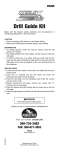
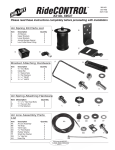
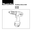
E4-WM5-Y367A00
MOUNTING INSTRUCTION
IMPORTANT!
PLEASE READ ALL INSTRUCTIONS FIRST!
If in doubt, please contact your local BILSTEIN dealer or our sales department before installation.
When replacing other brands, BILSTEIN shock absorbers should always be installed as a set. Installation
of shock absorbers, struts and cartridges requires special tools and expert knowledge. Accordingly,
installation of all BILSTEIN products must be performed by a qualified suspension specialist.
Always use a chassis hoist for the installation of BILSTEIN products, and make certain that the raised
vehicle is securely attached to the hoist to prevent the vehicle from slipping, falling, or moving during the
installation process.
If you choose to install any BILSTEIN product without the necessary special tools, expertise or
chassis hoist, you may subject yourself to the risk of serious bodily injury or death. If you elect not
to use a chassis hoist, at least make sure the vehicle is on level ground, that all tires on the ground during
installation are blocked to prevent movement, that at least two tires are on the ground at all times, and
that adequately secured safety stands (jack stands) are used to support the chassis. NEVER get under
the vehicle until you have checked to make sure all of these things are done.
All BILSTEIN products must only be used for the specific, intended application as indicated in the
application guide. Any use of any BILSTEIN product other than for its intended use may result in
serious bodily injury or death.
BILSTEIN suspension products are gas-filled and are highly pressurized. Never place any BILSTEIN
product in a vise or use a clamp on any BILSTEIN product; never apply heat near any BILSTEIN product,
and never attempt to open or repair any BILSTEIN product, in order to prevent serious bodily injury or
death. Any attempt to misuse, misapply, modify, or tamper with any BILSTEIN suspension product voids
any warranty and may result in serious bodily injury or death.
Do not use impact tools for loosening or tightening fasteners, because this may destroy the screw
threads. Self- locking nuts must only be used once!
Reuse original equipment components only if they are in good condition, otherwise replace them with new
components. Never remove the slight film of oil on the piston rod and seal.
All mounting fasteners for shocks and struts must be securely tightened before tension is placed on the
suspension system.
After installing any BILSTEIN product, the suspension caster and camber must be checked and/or
adjusted to comply with the vehicle manufacturer’s specifications. Also, the (load dependent) brake
compensator and the anti-lock brake system must be checked and/or reset to comply with the vehicle
manufacturer’s specifications. Also the headlight aim must be checked and adjusted.
Be sure to properly dispose of all old parts.
E4-WM5-Y367A00
MOUNTING INSTRUCTION
BILSTEIN 5160 Series Reservoir Shock Absorbers are designed to fit your vehicle’s original shock
mounts with no modifications. With the exception of reservoir placement, the 5160 Series shocks are
installed in the same manner as a standard replacement shock.
Note: The shocks and hardware depicted herein may differ slightly in appearance from the supplied
components.
In order to complete the installation, the following tools in addition to common hand tools will be required:
• Drill
• Size 7 drill bit (.201”)
• ¼”-20 tap and tap wrench
• Centerpunch and/or marker
• Tape measure
Front Shock Installation Procedure:
A.
Remove the existing front shocks from the vehicle following all procedures in the vehicle
manufacturer’s service manual.
B.
Install the front shock in the original location and attach the lower mount. Do not fully tighten at this
time.
C.
Using the supplied stem mounting hardware, install the upper mount. Please refer to Figure 1 for the
proper order of installation of the stem hardware. Make sure that the hose fitting on the shock is
facing outward. Refer to Figure 3 for the correct shock position.
D.
If a chassis hoist has been used, be sure to lower the vehicle such that its full weight is on the
suspension prior to fully tightening the fasteners.
E.
Tighten the lower mount fasteners to the vehicle manufacturer’s service manual torque
specification.
F.
Tighten the locknut on the stem to 19 lb•ft (26 N•m).
M10 locknut
upper
washer
upper
bushing
shock tower
lower
bushing
stem
Figure 1
lower
washer
E4-WM5-Y367A00
MOUNTING INSTRUCTION
Front Reservoir Bracket Installation Procedure:
A.
The front reservoir brackets are recommended to be installed on the outer frame rail, between the
upper shock mount and the forward upper control arm mount. Each front shock includes a bracket kit.
B.
Each bracket kit includes two ¼”-20 screws and two split washers. The frame rail must be drilled and
tapped in order to install the screws.
C.
Figure 2 depicts the recommended bracket position. The driver side is shown.
Figure 2
D.
Mark or scribe the side of the framerail with a line approximately centered between the upper shock
mount and the forward upper control arm mount. This line can be vertical or angled slightly forward so
it appears parallel with the shock body. Either position is acceptable.
E.
Place the bracket against the frame with the concave side facing outward and with the holes on
center with the marked line. Adjust the bracket position such that it approximately centered between
the top and bottom of the frame rail.
F.
Using the bracket as a template, mark the two hole locations with the marker and/or centerpunch.
Note: The hole centers in the bracket are exactly 5” apart and are slightly oversize to allow for some
variance in hole spacing on the frame.
G. Using the size 7 drill bit, drill a hole in side of the frame rail at each of the points marked. It is
recommended to drill a smaller pilot hole first to prevent the larger bit from wandering. Be sure to
keep the drill bit as perpendicular as possible to the side of the frame rail. It is also recommended to
use cutting oil to drill the frame.
H.
Tap the holes using the ¼”-20 tap. Be sure to keep the tap as perpendicular as possible to the side of
the frame rail. It is recommended to use cutting oil to tap the threads in the frame. Clean out the chips
and oil after tapping.
E4-WM5-Y367A00
MOUNTING INSTRUCTION
I.
Using the provided ¼”-20 bolts and split washers, install the reservoir bracket onto the frame. The
concave side of the bracket must face outward. It is recommended that a non-permanent thread
locking compound be used on the threads.
J.
Torque both bolts to 10 lb•ft (13.6 N•m).
K.
Using the provided hose clamps, slide the open bands through the thin slots on the sides of the
bracket.
L.
Secure the reservoir to the bracket using the hose clamps. The hose fittings are designed to swivel to
allow the reservoir and hose to be more easily positioned. Figure 3 depicts the reservoir installed.
Figure 3
M. Tighten the hose clamps until the reservoir cannot be manually rotated.
N.
The position of the brake line bracket on the upper control arm may need to be adjusted in order to
clear the reservoir and hose.
O. Carefully check for any possible interference between the reservoirs and any other components on
the vehicle, then make any necessary adjustments to the reservoir positions. The reservoir mounting
locations depicted herein are appropriate for most GM trucks for which this kit is intended, however,
some wheel/tire and/or lift kit combinations may create interference problems. It is the responsibility of
the installer to determine if the reservoirs are mounted appropriately and if there is any potential for
interference.
Rear Shock Installation Procedure:
A.
Remove the existing rear shocks from the vehicle following all procedures in the vehicle
manufacturer’s service manual.
B.
Before installing the rear shock/reservoir assemblies on the vehicle, use the supplied “piggyback”
hardware to mount each reservoir to its shock body. The shock reservoirs are mounted using two
polyurethane isolator blocks and two steel hose clamps. Please note that the position of each
reservoir relative to its shock body is different for each side of the vehicle. These positions are
depicted in Figures 4 and 5. The hose fittings are designed to swivel and will allow the reservoir and
hose to be easily moved.
E4-WM5-Y367A00
MOUNTING INSTRUCTION
Figure 4. rear driver side
Figure 5. rear passenger side
C.
The isolator blocks should be spaced approximately 6”-8” apart. The hose clamps should be
positioned in line with the isolator blocks
D.
Tighten the hose clamps sufficiently to prevent the reservoir from slipping, but loose enough to allow
for small subsequent adjustments of position. The hose clamps will be tightened further once the
shock/reservoir assembly is installed on the vehicle and the proper reservoir position has been
confirmed.
E.
Install the complete shock/reservoir assemblies on the vehicle. All original fasteners can be reused
for the rear shocks.
F.
If a chassis hoist has been used, be sure to lower the vehicle such that its full weight is on the
suspension prior to fully tightening the fasteners.
G. Tighten all fasteners to the vehicle manufacturer’s service manual torque specifications.
H.
Carefully check for any possible interference between the reservoirs and any other components on
the vehicle, then make any necessary adjustments to the reservoir positions. The reservoir mounting
locations depicted herein are appropriate for most GM trucks for which this kit is intended, however,
some wheel/tire and/or lift kit combinations may create interference problems. It is the responsibility of
the installer to determine if the reservoirs are mounted appropriately and if there is any potential for
interference.
I.
If no potential interference is found, tighten the hose clamps until the reservoir cannot be manually
moved independent of the shock body. This completes the installation.
BILSTEIN SUSPENSION
SUSPENSION SYSTEMS