1
User’s Manual
There are corrections on this document.
For the information of corrections, click the icon on the left or
refer to the page below.
http://tool-support.renesas.com/eng/toolnews/131016/tn5.htm
RI850V4
Real-Time Operating System
User’s Manual: Coding
Target Tool
RI850V4
All information contained in these materials, including products and product specifications,
represents information on the product at the time of publication and is subject to change by
Renesas Electronics Corp. without notice. Please review the latest information published by
Renesas Electronics Corp. through various means, including the Renesas Electronics Corp.
website (http://www.renesas.com).
www.renesas.com
Rev.1.00
Apr 2011
Notice
1.
2.
3.
4.
5.
6.
7.
All information included in this document is current as of the date this document is issued. Such information, however, is
subject to change without any prior notice. Before purchasing or using any Renesas Electronics products listed herein, please
confirm the latest product information with a Renesas Electronics sales office. Also, please pay regular and careful attention to
additional and different information to be disclosed by Renesas Electronics such as that disclosed through our website.
Renesas Electronics does not assume any liability for infringement of patents, copyrights, or other intellectual property rights
of third parties by or arising from the use of Renesas Electronics products or technical information described in this document.
No license, express, implied or otherwise, is granted hereby under any patents, copyrights or other intellectual property rights
of Renesas Electronics or others.
You should not alter, modify, copy, or otherwise misappropriate any Renesas Electronics product, whether in whole or in part.
Descriptions of circuits, software and other related information in this document are provided only to illustrate the operation of
semiconductor products and application examples. You are fully responsible for the incorporation of these circuits, software,
and information in the design of your equipment. Renesas Electronics assumes no responsibility for any losses incurred by
you or third parties arising from the use of these circuits, software, or information.
When exporting the products or technology described in this document, you should comply with the applicable export control
laws and regulations and follow the procedures required by such laws and regulations. You should not use Renesas
Electronics products or the technology described in this document for any purpose relating to military applications or use by
the military, including but not limited to the development of weapons of mass destruction. Renesas Electronics products and
technology may not be used for or incorporated into any products or systems whose manufacture, use, or sale is prohibited
under any applicable domestic or foreign laws or regulations.
Renesas Electronics has used reasonable care in preparing the information included in this document, but Renesas Electronics
does not warrant that such information is error free. Renesas Electronics assumes no liability whatsoever for any damages
incurred by you resulting from errors in or omissions from the information included herein.
Renesas Electronics products are classified according to the following three quality grades: “Standard”, “High Quality”, and
“Specific”. The recommended applications for each Renesas Electronics product depends on the product’s quality grade, as
indicated below. You must check the quality grade of each Renesas Electronics product before using it in a particular
application. You may not use any Renesas Electronics product for any application categorized as “Specific” without the prior
written consent of Renesas Electronics. Further, you may not use any Renesas Electronics product for any application for
which it is not intended without the prior written consent of Renesas Electronics. Renesas Electronics shall not be in any way
liable for any damages or losses incurred by you or third parties arising from the use of any Renesas Electronics product for an
application categorized as “Specific” or for which the product is not intended where you have failed to obtain the prior written
consent of Renesas Electronics. The quality grade of each Renesas Electronics product is “Standard” unless otherwise
expressly specified in a Renesas Electronics data sheets or data books, etc.
“Standard”:
8.
9.
10.
11.
12.
Computers; office equipment; communications equipment; test and measurement equipment; audio and visual
equipment; home electronic appliances; machine tools; personal electronic equipment; and industrial robots.
“High Quality”: Transportation equipment (automobiles, trains, ships, etc.); traffic control systems; anti-disaster systems; anticrime systems; safety equipment; and medical equipment not specifically designed for life support.
“Specific”:
Aircraft; aerospace equipment; submersible repeaters; nuclear reactor control systems; medical equipment or
systems for life support (e.g. artificial life support devices or systems), surgical implantations, or healthcare
intervention (e.g. excision, etc.), and any other applications or purposes that pose a direct threat to human life.
You should use the Renesas Electronics products described in this document within the range specified by Renesas Electronics,
especially with respect to the maximum rating, operating supply voltage range, movement power voltage range, heat radiation
characteristics, installation and other product characteristics. Renesas Electronics shall have no liability for malfunctions or
damages arising out of the use of Renesas Electronics products beyond such specified ranges.
Although Renesas Electronics endeavors to improve the quality and reliability of its products, semiconductor products have
specific characteristics such as the occurrence of failure at a certain rate and malfunctions under certain use conditions. Further,
Renesas Electronics products are not subject to radiation resistance design. Please be sure to implement safety measures to
guard them against the possibility of physical injury, and injury or damage caused by fire in the event of the failure of a
Renesas Electronics product, such as safety design for hardware and software including but not limited to redundancy, fire
control and malfunction prevention, appropriate treatment for aging degradation or any other appropriate measures. Because
the evaluation of microcomputer software alone is very difficult, please evaluate the safety of the final products or system
manufactured by you.
Please contact a Renesas Electronics sales office for details as to environmental matters such as the environmental
compatibility of each Renesas Electronics product. Please use Renesas Electronics products in compliance with all applicable
laws and regulations that regulate the inclusion or use of controlled substances, including without limitation, the EU RoHS
Directive. Renesas Electronics assumes no liability for damages or losses occurring as a result of your noncompliance with
applicable laws and regulations.
This document may not be reproduced or duplicated, in any form, in whole or in part, without prior written consent of Renesas
Electronics.
Please contact a Renesas Electronics sales office if you have any questions regarding the information contained in this
document or Renesas Electronics products, or if you have any other inquiries.
(Note 1) “Renesas Electronics” as used in this document means Renesas Electronics Corporation and also includes its majorityowned subsidiaries.
(Note 2) “Renesas Electronics product(s)” means any product developed or manufactured by or for Renesas Electronics.
How to Use This Manual
Readers
This manual is intended for users who design and develop application systems using
V850 microcontroller products.
Purpose
This manual is intended for users to understand the functions of real-time OS
"RI850V4" manufactured by Renesas Electronics, described the organization listed
below.
Organization
This manual consists of the following major sections.
CHAPTER 1 OVERVIEW
CHAPTER 2 SYSTEM CONSTRUCTION
CHAPTER 3 TASK MANAGEMENT FUNCTIONS
CHAPTER 4 TASK DEPENDENT SYNCHRONIZATION FUNCTIONS
CHAPTER 5 TASK EXCEPTION HANDLING FUNCTIONS
CHAPTER 6 SYNCHRONIZATION AND COMMUNICATION FUNCTIONS
CHAPTER 7 EXTENDED SYNCHRONIZATION AND COMMUNICATION FUNCTIONS
CHAPTER 8 MEMORY POOL MANAGEMENT FUNCTIONS
CHAPTER 9 TIME MANAGEMENT FUNCTIONS
CHAPTER 10 SYSTEM STATE MANAGEMENT FUNCTIONS
CHAPTER 11 INTERRUPT MANAGEMENT FUNCTIONS
CHAPTER 12 SERVICE CALL MANAGEMENT FUNCTIONS
CHAPTER 13 SYSTEM CONFIGURATION MANAGEMENT FUNCTIONS
CHAPTER 14 SCHEDULER
CHAPTER 15 SYSTEM INITIALIZATION ROUTINE
CHAPTER 16 DATA MACROS
CHAPTER 17 SERVICE CALLS
CHAPTER 18 SYSTEM CONFIGURATION FILE
CHAPTER 19 CONFIGURATOR CF850V4
APPENDIX A WINDOW REFERENCE
APPENDIX B FLOATING-POINT OPERATION FUNCTION
APPENDIX C INDEX
How to read this manual
It is assumed that the readers of this manual have general knowledge in the fields of
electrical engineering, logic circuits, microcontrollers, C language, and assemblers.
To understand the hardware functions of the V850 microcontroller
→ Refer to the User’s Manual of each product.
Conventions
Data significance:
Higher digits on the left and lower digits on the right
Note:
Footnote for item marked with Note in the text
Caution:
Information requiring particular attention
Remark:
Supplementary information
Numerical representation: Binary...XXXX or XXXXB
Decimal...XXXX
Hexadecimal...0xXXXX
Prefixes indicating power of 2 (address space and memory capacity):
K (kilo)
210 = 1024
M (mega)
220 = 10242
Related Documents
Refer to the documents listed below when using this manual.
The related documents indicated in this publication may include preliminary versions.
However, preliminary versions are not marked as such.
Documents related to development tools (User’s Manuals)
Document Name
RI Series
RI78V4
RI850V4
Document No.
Start
R20UT0509E
Message
R20UT0510E
Coding
R20UT0511E
Debug
R20UT0520E
Analysis
R20UT0513E
Internal Structure
R20UT0514E
Coding
This document
Debug
R20UT0516E
Analysis
R20UT0517E
Internal Structure
R20UT0518E
RI850MP
Coding
R20UT0519E
CubeSuite+
Start
R20UT0545E
Integrated Development Environment
78K0 Design
R20UT0546E
78K0R Design
R20UT0547E
RL78 Design
R20UT0548E
V850 Design
R20UT0549E
R8C Design
R20UT0550E
78K0 Coding
R20UT0551E
Caution
RL78,78K0R Coding
R20UT0552E
V850 Coding
R20UT0553E
Coding for CX Compiler
R20UT0554E
R8C Coding
R20UT0576E
78K0 Build
R20UT0555E
RL78,78K0R Build
R20UT0556E
V850 Build
R20UT0557E
Build for CX Compiler
R20UT0558E
R8C Build
R20UT0575E
78K0 Debug
R20UT0559E
78K0R Debug
R20UT0560E
RL78 Debug
R20UT0561E
The related documents listed above are subject to change without notice. Be sure to use the
latest edition of each document when designing.
All trademarks or registered trademarks in this document are the property of their respective
owners.
[MEMO]
[MEMO]
[MEMO]
TABLE OF CONTENTS
CHAPTER 1 OVERVIEW ... 15
1.1 Outline ... 15
1.1.1 Real-time OS ... 15
1.1.2 Multi-task OS ... 15
CHAPTER 2 SYSTEM CONSTRUCTION ... 16
2.1 Outline ... 16
2.2 Coding of Target-Dependent Module ... 18
2.2.1 Creating target-dependent module library ... 19
2.3 Coding Processing Programs ... 20
2.4 Coding System Configuration File ... 20
2.5 Coding User-Own Coding Module ... 21
2.6 Coding Directive File ... 22
2.7 Creating Load Module ... 23
CHAPTER 3 TASK MANAGEMENT FUNCTIONS ... 27
3.1 Outline ... 27
3.2 Tasks ... 27
3.2.1 Task state ... 27
3.2.2 Task priority ... 29
3.2.3 Basic form of tasks ... 30
3.2.4 Internal processing of task ... 31
3.3 Creat Task ... 32
3.4 Activate Task ... 32
3.4.1 Queuing an activation request ... 32
3.4.2 Not queuing an activation request ... 33
3.5 Cancel Task Activation Requests ... 34
3.6 Terminate Task ... 35
3.6.1 Terminate invoking task ... 35
3.6.2 Terminate task ... 36
3.7 Change Task Priority ... 37
3.8 Reference Task Priority ... 38
3.9 Reference Task State ... 39
3.9.1 Reference task state ... 39
3.9.2 Reference task state (simplified version) ... 40
3.10 Target-Dependent Module ... 41
3.10.1 Post-overflow processing ... 41
3.11 Memory Saving ... 42
3.11.1 Disable preempt ... 42
CHAPTER 4 TASK DEPENDENT SYNCHRONIZATION FUNCTIONS ... 43
4.1 Outline ... 43
4.2 Put Task to Sleep ... 43
4.2.1 Waiting forever ... 43
4.2.2 With timeout ... 45
4.3 Wakeup Task ... 46
4.4 Cancel Task Wakeup Requests ... 47
4.5 Release Task from Waiting ... 48
4.6 Suspend Task ... 49
4.7 Resume Suspended Task ... 50
4.7.1 Resume suspended task ... 50
4.7.2 Forcibly resume suspended task ... 51
4.8 Delay Task ... 52
4.9 Differences Between Wakeup Wait with Timeout and Time Elapse Wait ... 53
CHAPTER 5 TASK EXCEPTION HANDLING FUNCTIONS ... 54
5.1 Outline ... 54
5.2 Task Exception Handling Routines ... 54
5.2.1 Basic form of task exception handling routines ... 54
5.2.2 Internal processing of task exception handling routine ... 55
5.3 Define Task Exception Handling Routine ... 55
5.4 Raise Task Exception Handling Routine ... 56
5.5 Disabling and Enabling Activation of Task Exception Handling Routines ... 57
5.6 Reference Task Exception Handling Disable/Enable State ... 59
5.7 Reference Detailed Information of Task Exception Handling Routine ... 60
CHAPTER 6 SYNCHRONIZATION AND COMMUNICATION FUNCTIONS ... 61
6.1 Outline ... 61
6.2 Semaphores ... 61
6.2.1 Create semaphore ... 61
6.2.2 Acquire semaphore resource ... 62
6.2.3 Release semaphore resource ... 65
6.2.4 Reference semaphore state ... 66
6.3 Eventflags ... 67
6.3.1 Create eventflag ... 67
6.3.2 Set eventflag ... 68
6.3.3 Clear eventflag ... 69
6.3.4 Wait for eventflag ... 70
6.3.5 Reference eventflag state ... 75
6.4 Data Queues ... 76
6.4.1 Create data queue ... 76
6.4.2 Send to data queue ... 77
6.4.3 Forced send to data queue ... 82
6.4.4 Receive from data queue ... 83
6.4.5 Reference data queue state ... 88
6.5 Mailboxes ... 89
6.5.1 Messages ... 89
6.5.2 Create mailbox ... 90
6.5.3 Send to mailbox ... 91
6.5.4 Receive from mailbox ... 92
6.5.5 Reference mailbox state ... 95
CHAPTER 7 EXTENDED SYNCHRONIZATION AND COMMUNICATION FUNCTIONS ...
96
7.1 Outline ... 96
7.2 Mutexes ... 96
7.2.1 Differences from semaphores ... 96
7.2.2 Create mutex ... 97
7.2.3 Lock mutex ... 98
7.2.4 Unlock mutex ... 101
7.2.5 Reference mutex state ... 102
CHAPTER 8 MEMORY POOL MANAGEMENT FUNCTIONS ... 103
8.1 Outline ... 103
8.2 Fixed-Sized Memory Pools ... 104
8.2.1 Create fixed-sized memory pool ... 104
8.2.2 Acquire fixed-sized memory block ... 105
8.2.3 Release fixed-sized memory block ... 110
8.2.4 Reference fixed-sized memory pool state ... 111
8.3 Variable-Sized Memory Pools ... 112
8.3.1 Create variable-sized memory pool ... 112
8.3.2 Acquire variable-sized memory block ... 113
8.3.3 Release variable-sized memory block ... 118
8.3.4 Reference variable-sized memory pool state ... 119
CHAPTER 9 TIME MANAGEMENT FUNCTIONS ... 120
9.1 Outline ... 120
9.2 System Time ... 120
9.2.1 Base clock timer interrupt ... 120
9.2.2 Base clock interval ... 120
9.3 Timer Operations ... 121
9.3.1 Delayed task wakeup ... 121
9.3.2 Timeout ... 121
9.3.3 Cyclic handlers ... 121
9.3.4 Create cyclic handler ... 122
9.4 Set System Time ... 123
9.5 Reference System Time ... 124
9.6 Start Cyclic Handler Operation ... 125
9.7 Stop Cyclic Handler Operation ... 127
9.8 Reference Cyclic Handler State ... 128
CHAPTER 10 SYSTEM STATE MANAGEMENT FUNCTIONS ... 129
10.1 Outline ... 129
10.2 Rotate Task Precedence ... 129
10.3 Forced Scheduler Activation ... 131
10.4 Reference Task ID in the RUNNING State ... 132
10.5 Lock the CPU ... 133
10.6 Unlock the CPU ... 135
10.7 Reference CPU State ... 137
10.8 Disable Dispatching ... 138
10.9 Enable Dispatching ... 140
10.10 Reference Dispatching State ... 142
10.11 Reference Contexts ... 143
10.12 Reference Dispatch Pending State ... 144
CHAPTER 11 INTERRUPT MANAGEMENT FUNCTIONS ... 145
11.1 Outline ... 145
11.2 Target-Dependent Module ... 145
11.2.1 Service call "dis_int" ... 145
11.2.2 Service call "ena_int" ... 147
11.2.3 Interrupt mask setting processing (overwrite setting) ... 148
11.2.4 Interrupt mask setting processing (OR setting) ... 149
11.2.5 Interrupt mask acquire processing ... 150
11.3 User-Own Coding Module ... 151
11.3.1 Interrupt entry processing ... 151
11.4 Interrupt Handlers ... 152
11.4.1 Basic form of interrupt handlers ... 152
11.4.2 Internal processing of interrupt handler ... 152
11.4.3 Define interrupt handler ... 153
11.5 Maskable Interrupt Acknowledgement Status in Processing Programs ... 154
11.6 Disable Interrupt ... 155
11.7 Enable Interrupt ... 157
11.8 Change Interrupt Mask ... 159
11.9 Reference Interrupt Mask ... 160
11.10 Non-Maskable Interrupts ... 161
11.11 Base Clock Timer Interrupts ... 161
11.12 Multiple Interrupts ... 161
CHAPTER 12 SERVICE CALL MANAGEMENT FUNCTIONS ... 162
12.1 Outline ... 162
12.2 Extended Service Call Routines ... 162
12.2.1 Basic form extended service call routines ... 162
12.2.2 Internal processing of extended service call routine ... 163
12.3 Define Extended Service Call Routine ... 163
12.4 Invoke Extended Service Call Routine ... 164
CHAPTER 13 SYSTEM CONFIGURATION MANAGEMENT FUNCTIONS ... 165
13.1 Outline ... 165
13.2 User-Own Coding Module ... 165
13.2.1 CPU exception entry processing ... 165
13.2.2 Initialization routine ... 166
13.2.3 Define initialization routine ... 167
13.3 CPU Exception Handlers ... 168
13.3.1 Basic form of CPU exception handlers ... 168
13.3.2 Internal processing of CPU exception handler ... 168
13.4 Define CPU Exception Handler ... 169
CHAPTER 14 SCHEDULER ... 170
14.1 Outline ... 170
14.2 Drive Method ... 170
14.3 Scheduling Method ... 170
14.3.1 Ready queue ... 171
14.4 Scheduling Lock Function ... 172
14.5 Idle Routine ... 173
14.5.1 Basic form of idle routine ... 173
14.5.2 Internal processong of idle routine ... 173
14.6 Define Idle Routine ... 174
14.7 Scheduling in Non-Tasks ... 174
CHAPTER 15 SYSTEM INITIALIZATION ROUTINE ... 175
15.1 Outline ... 175
15.2 User-Own Coding Module ... 176
15.2.1 Boot processing ... 176
15.3 Kernel Initialization Module ... 178
CHAPTER 16 DATA MACROS ... 180
16.1 Data Types ... 180
16.2 Packet Formats ... 182
16.2.1 Task state packet ... 182
16.2.2 Task state packet (simplified version) ... 184
16.2.3 Task exception handling routine state packet ... 185
16.2.4 Semaphore state packet ... 186
16.2.5 Eventflag state packet ... 187
16.2.6 Data queue state packet ... 188
16.2.7 Message packet ... 189
16.2.8 Mailbox state packet ... 190
16.2.9 Mutex state packet ... 191
16.2.10 Fixed-sized memory pool state packet ... 192
16.2.11 Variable-sized memory pool state packet ... 193
16.2.12 System time packet ... 194
16.2.13 Cyclic handler state packet ... 195
16.3 Data Macros ... 196
16.3.1 Current state ... 196
16.3.2 Processing program attributes ... 197
16.3.3 Management object attributes ... 197
16.3.4 Service call operating modes ... 198
16.3.5 Return value ... 198
16.3.6 Kernel configuration constants ... 199
16.4 Conditional Compile Macro ... 200
CHAPTER 17 SERVICE CALLS ... 201
17.1 Outline ... 201
17.1.1 Call service call ... 202
17.2 Explanation of Service Call ... 203
17.2.1 Task management functions ... 205
17.2.2 Task dependent synchronization functions ... 221
17.2.3 Task exception handling functions ... 234
17.2.4 Synchronization and communication functions (semaphores) ... 242
17.2.5 Synchronization and communication functions (eventflags) ... 251
17.2.6 Synchronization and communication functions (data queues) ... 261
17.2.7 Synchronization and communication functions (mailboxes) ... 275
17.2.8 Extended synchronization and communication functions (mutexes) ... 285
17.2.9 Memory pool management functions (fixed-sized memory pools) ... 294
17.2.10 Memory pool management functions (variable-sized memory pools) ... 304
17.2.11 Time management functions ... 315
17.2.12 System state management functions ... 323
17.2.13 Interrupt management functions ... 336
17.2.14 Service call management functions ... 341
CHAPTER 18 SYSTEM CONFIGURATION FILE ... 343
18.1 Outline ... 343
18.2 Configuration Information ... 345
18.2.1 Cautions ... 346
18.3 Declarative Information ... 347
18.3.1 Header file declaration ... 347
18.4 System Information ... 348
18.4.1 RI series information ... 348
18.4.2 Basic information ... 349
18.4.3 Initial FPSR register information ... 351
18.4.4 Memory area information ... 352
18.5 Static API Information ... 353
18.5.1 Task information ... 353
18.5.2 Task exception handling routine information ... 355
18.5.3 Semaphore information ... 356
18.5.4 Eventflag information ... 357
18.5.5 Data queue information ... 358
18.5.6 Mailbox information ... 359
18.5.7 Mutex information ... 360
18.5.8 Fixed-sized memory pool information ... 361
18.5.9 Variable-sized memory pool information ... 362
18.5.10 Cyclic handler information ... 363
18.5.11 Interrupt handler information ... 365
18.5.12 CPU exception handler information ... 366
18.5.13 Extended service call routine information ... 367
18.5.14 Initialization routine information ... 368
18.5.15 Idle routine information ... 369
18.6 Memory Capacity Estimation ... 370
18.6.1 .kernel_const section ... 370
18.6.2 .kernel_info section ... 371
18.6.3 .kernel_data section/user-defined section ... 372
18.6.4 .kernel_system section ... 375
18.7 Description Examples ... 376
CHAPTER 19 CONFIGURATOR CF850V4 ... 377
19.1 Outline ... 377
19.2 Activation Method ... 378
19.2.1 Activating from command line ... 378
19.2.2 Activating from CubeSuite+ ... 380
19.2.3 Command file ... 381
19.2.4 Command input examples ... 382
APPENDIX A WINDOW REFERENCE ... 383
A.1 Description ... 383
APPENDIX B FLOATING-POINT OPERATION FUNCTION ... 398
APPENDIX C INDEX ... 399
RI850V4 Ver.1.00.00
CHAPTER 1 OVERVIEW
CHAPTER 1 OVERVIEW
1.1
Outline
The RI850V4 is a built-in real-time, multi-task OS that provides a highly efficient real-time, multi-task environment to
increases the application range of processor control units.
The RI850V4 is a high-speed, compact OS capable of being stored in and run from the ROM of a target system.
1.1.1
Real-time OS
Control equipment demands systems that can rapidly respond to events occurring both internal and external to the
equipment. Conventional systems have utilized simple interrupt handling as a means of satisfying this demand. As control
equipment has become more powerful, however, it has proved difficult for systems to satisfy these requirements by means
of simple interrupt handling alone.
In other words, the task of managing the order in which internal and external events are processed has become
increasingly difficult as systems have increased in complexity and programs have become larger.
Real-time OS has been designed to overcome this problem.
The main purpose of a real-time OS is to respond to internal and external events rapidly and execute programs in the
optimum order.
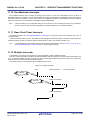
1.1.2
Multi-task OS
A "task" is the minimum unit in which a program can be executed by an OS. "Mult-task" is the name given to the mode
of operation in which a single processor processes multiple tasks concurrently.
Actually, the processor can handle no more than one program (instruction) at a time. But, by switching the processor’s
attention to individual tasks on a regular basis (at a certain timing) it appears that the tasks are being processed
simultaneously.
A multi-task OS enables the parallel processing of tasks by switching the tasks to be executed as determined by the
system.
One important purpose of a multi-task OS is to improve the throughput of the overall system through the parallel
processing of multiple tasks.
R20UT0515EJ0100 Rev.1.00
Apr 01, 2011
Page 15 of 406
RI850V4 Ver.1.00.00
CHAPTER 2 SYSTEM CONSTRUCTION
CHAPTER 2 SYSTEM CONSTRUCTION
This chapter describes how to build a system (load module) that uses the functions provided by the RI850V4.
2.1
Outline
System building consists in the creation of a load module using the files (kernel library, etc.) installed on the user
development environment (host machine) from the RI850V4's supply media.
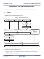
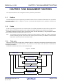
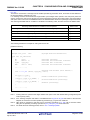
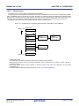
The following shows the procedure for organizing the system.
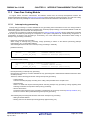
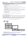
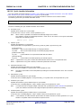
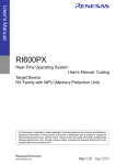
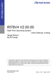
Figure 2-1 Example of System Construction
Target-Dependent Module
Processing Programs
User-own Coding Module
System Configuration File
Configurator
Information Files
C compiler / Assembler
Object Files
Directive File
Library Files
- Kernel Library
- Stabdard Library
- Runtime Library
erc.
Archiver (CA850) / Librarian (CX)
Target-Dependent Module Library
Linker
Load Module
The RI850V4 provides a sample program with the files necessary for generating a load module.
The sample programs are stored in the following folder.
<ri_sample> = <CubeSuite+_root>\SampleProjects\V850E\device_nametype(compiler_name)Vx.xx\appli
- <CubeSuite+_root>
Indicates the installation folder of CubeSuite+.
R20UT0515EJ0100 Rev.1.00
Apr 01, 2011
Page 16 of 406
RI850V4 Ver.1.00.00
CHAPTER 2 SYSTEM CONSTRUCTION
The default folder is “C:\Program Files\Renesas Electronics\CubeSuite+\.
- SampleProjects
Indicates the sample project folder of CubeSuite+.
- V850E
Indicates the sample project folder of V850E.
- device_nametype(compiler_name)Vx.xx
Indicates the sample project folder of the RI850V4.
device_name:
Indicates the device name which the sample is provided.
But since the "/" character cannot be used in folder names, any "/" characters in the device name
are replaced with the "_" character.
:
Indicates a space.
type:
Indicates the type of the sample program.
compiler_name: Indicates the compiler package name.
Vx.xx:
Indicates the version of the sample project of the RI850V4.
- appli
Indicates the folder which the sample program provided by the RI850V4 is stored.
R20UT0515EJ0100 Rev.1.00
Apr 01, 2011
Page 17 of 406
RI850V4 Ver.1.00.00
2.2
CHAPTER 2 SYSTEM CONSTRUCTION
Coding of Target-Dependent Module
To support various execution environments, the RI850V4 extracts hardware-dependent processing that is required to
execute processing as target-dependent modules. This enhances portability for various execution environments and
facilitates customization as well.
The following lists the target-dependent modules extracted for each function.
- TASK MANAGEMENT FUNCTIONS
- Post-overflow processing
A routine dedicated to post-overflow processing (function name: _kernel_stk_overflow), which is extracted as a
target-dependent module, for executing post processing when a stack required by the RI850V4 or the processing
program to perform execution overflows. It is called from the RI850V4 when a stack overflows.
- INTERRUPT MANAGEMENT FUNCTIONS
- Service call "dis_int"
A routine dedicated to maskable interrupt acknowledge processing (function name: _kernel_usr_dis_int), which
is extracted as a target-dependent module, for disabling acknowledgment of maskable interrupt. It is called when
service call dis_int is issued from the processing program.
- Service call "ena_int"
A routine dedicated to maskable interrupt acknowledge processing (function name: _kernel_usr_ena_int), which
is extracted as a target-dependent module, for enabling acknowledgment of maskable interrupt. It is called when
service call ena_int is issued from the processing program.
- Interrupt mask setting processing (overwrite setting)
A routine dedicated to interrupt mask pattern processing (function name: _kernel_usr_set_intmsk), which is
extracted as a target-dependent module, for setting the interrupt mask pattern specified by the relevant user-own
function parameter to the interrupt control register xxICn or interrupt mask flag xxMKn of the interrupt mask
register IMRm. It is called when service call unl_cpu, iunl_cpu, chg_ims, or ichg_ims is issued from the
processing program.
- Interrupt mask setting processing (OR setting)
A routine dedicated to interrupt mask pattern processing (function name: _kernel_usr_msk_intmsk), which is
extracted as a target-dependent module, for ORing the interrupt mask pattern specified by the relevant user-own
function parameter and the CPU interrupt mask pattern (the values of interrupt control register xxICn or interrupt
mask flag xxMKn of the interrupt mask register IMRm) and storing the result to the interrupt mask flag xxMKn of
the target register. It is called when service call loc_cpu or iloc_cpu is issued from the processing program.
- Interrupt mask acquire processing
A routine dedicated to interrupt mask pattern acquire processing (function name: _kernel_usr_get_intmsk), which
is extracted as a target-dependent module, for storing the CPU interrupt mask pattern (the values of interrupt
control register xxICn or interrupt mask flag xxMKn of the interrupt mask register IMRm) into the area specified
by the relevant user-own function parameter. It is called when service call loc_cpu, iloc_cpu, get_ims, or iget_ims
is issued from the processing program.
Note
For details on the target-dependent modules, refer to "CHAPTER 3 TASK MANAGEMENT FUNCTIONS" and
"CHAPTER 11 INTERRUPT MANAGEMENT FUNCTIONS".
R20UT0515EJ0100 Rev.1.00
Apr 01, 2011
Page 18 of 406
RI850V4 Ver.1.00.00
2.2.1
CHAPTER 2 SYSTEM CONSTRUCTION
Creating target-dependent module library
Execute the C compiler, assembler and etc. for C source and assembler source files created in "2.2 Coding of TargetDependent Module" to generate library files (target-dependent module libraries).
The following lists the files required for generating target-dependent module libraries.
- Post-overflow processing
- Service call "dis_int"
- Service call "ena_int"
- Interrupt mask setting processing (overwrite setting)
- Interrupt mask setting processing (OR setting)
- Interrupt mask acquire processing
R20UT0515EJ0100 Rev.1.00
Apr 01, 2011
Page 19 of 406
RI850V4 Ver.1.00.00
2.3
CHAPTER 2 SYSTEM CONSTRUCTION
Coding Processing Programs
Code the processing that should be implemented in the system.
In the RI850V4, the processing program is classified into the following seven types, in accordance with the types and
purposes of the processing that should be implemented.
- Tasks
A task is processing program that is not executed unless it is explicitly manipulated via service calls provided by the
RI850V4, unlike other processing programs (cyclic handler, interrupt handler, etc.).
- Task Exception Handling Routines
The task exception handling routine is a routine dedicated to task exception handling, and is activated when a task
exception handling request is issued.
The RI850V4 positions task exception handling routines as extensions of the task for which a task exception handling
request is issued. A task exception handling routine is therefore activated when the task for which a task exception
handling request is issued moves to the RUNNING state.
- Cyclic handlers
The cyclic handler is a routine dedicated to cycle processing that is activated periodically at a constant interval
(activation cycle).
The RI850V4 handles the cyclic handler as a "non-task (module independent from tasks)". Therefore, even if a task
with the highest priority in the system is being executed, the processing is suspended when a specified activation
cycle has come, and the control is passed to the cyclic handler.
- Interrupt Handlers
The interrupt handler is a routine dedicated to interrupt servicing that is activated when an interrupt occurs.
The RI850V4 handles the interrupt handler as a "non-task (module independent from tasks)". Therefore, even if a task
with the highest priority in the system is being executed, the processing is suspended when an interrupt occurs, and
the control is passed to the interrupt handler.
- Extended Service Call Routines
This is a routine to which user-defined functions are registered in the RI850V4, and will never be executed unless it is
called explicitly, using service calls provided by the RI850V4.
The RI850V4 positions extended service call routines as extensions of the processing program that called the
extended service call routine.
- CPU Exception Handlers
The CPU exception handler is a routine dedicated to CPU exception servicing that is activated when a CPU exception
occurs.
The RI850V4 handles the CPU exception handler as a "non-task (module independent from tasks)". Therefore, even
if a task with the highest priority in the system is being executed, the processing is suspended when a CPU exception
occurs, and the control is passed to the CPU exception handler.
Note
2.4
For details about the processing programs, refer to "CHAPTER 3 TASK MANAGEMENT FUNCTIONS",
"CHAPTER 5 TASK EXCEPTION HANDLING FUNCTIONS", "CHAPTER 9 TIME MANAGEMENT
FUNCTIONS", "CHAPTER 11 INTERRUPT MANAGEMENT FUNCTIONS", "CHAPTER 12 SERVICE CALL
MANAGEMENT FUNCTIONS", "CHAPTER 13 SYSTEM CONFIGURATION MANAGEMENT FUNCTIONS".
Coding System Configuration File
Code the SYSTEM CONFIGURATION FILE required for creating information files (system information table file, system
information header file, entry file) that contain data to be provided for the RI850V4.
Note
For details about the system configuration file, refer to "CHAPTER 18 SYSTEM CONFIGURATION FILE".
R20UT0515EJ0100 Rev.1.00
Apr 01, 2011
Page 20 of 406
RI850V4 Ver.1.00.00
2.5
CHAPTER 2 SYSTEM CONSTRUCTION
Coding User-Own Coding Module
To support various execution environments, the RI850V4 extracts hardware-dependent processing that is required to
execute processing as user-own coding modules, and provides it as sample source files. This enhances portability for
various execution environments and facilitates customization as well.
The following lists the user-own coding modules extracted for each function.
- INTERRUPT MANAGEMENT FUNCTIONS
- Interrupt entry processing
A routine dedicated to entry processing that is extracted as a user-own coding module to assign instructions to
branch to relevant processing (such as interrupt preprocessing), to the handler address to which the CPU forcibly
passes the control when an interrupt occurs.
Interrupt entry processing for interrupt handlers defined in Interrupt handler information during configuration is
included in the entry file created by executing the configurator for the system configuration file created during
configuration. If customization of interrupt entry processing is unnecessary, use of the relevant entry file therefore
makes coding of interrupt entry processing unnecessary.
- SYSTEM CONFIGURATION MANAGEMENT FUNCTIONS
- CPU exception entry processing
A routine dedicated to entry processing that is extracted as a user-own coding module to assign instructions to
branch to relevant processing (such as CPU exception preprocessing or Boot processing), to the handler
address to which the CPU forcibly passes the control when a CPU exception occurs.
CPU exception handling for CPU exception handlers defined in CPU exception handler information during
configuration is included in the entry file created by executing the configurator for the system configuration file
created during configuration. If customization of CPU exception entry processing is unnecessary, use of the
relevant entry file therefore makes coding of CPU exception entry processing unnecessary.
- Initialization routine
A routine dedicated to initialization processing that is extracted as a user-own coding module to initialize the
hardware dependent on the user execution environment (such as the peripheral controller), and is called from the
Kernel Initialization Module.
- SCHEDULER
- Idle Routine
A routine dedicated to idle processing that is extracted from the SCHEDULER as a user-own coding module to
utilize the standby function provided by the CPU (to achieve the low-power consumption system), and is called
from the scheduler when there no longer remains a task subject to scheduling by the RI850V4 (task in the
RUNNING or READY state) in the system.
- SYSTEM INITIALIZATION ROUTINE
- Boot processing
A routine dedicated to initialization processing that is extracted as a user-own coding module to initialize the
minimum required hardware for the RI850V4 to perform processing, and is called from CPU exception entry
processing.
Note
For details about the user-own coding module, refer to "CHAPTER 11 INTERRUPT MANAGEMENT
FUNCTIONS", "CHAPTER 13 SYSTEM CONFIGURATION MANAGEMENT FUNCTIONS", "CHAPTER 14
SCHEDULER", "CHAPTER 15 SYSTEM INITIALIZATION ROUTINE".
R20UT0515EJ0100 Rev.1.00
Apr 01, 2011
Page 21 of 406
RI850V4 Ver.1.00.00
2.6
CHAPTER 2 SYSTEM CONSTRUCTION
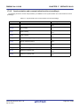
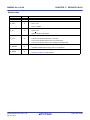
Coding Directive File
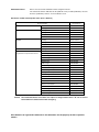
Code the directive file used by the user to fix the address allocation done by the linker. In the RI850V4, the allocation
destinations (section names) of management objects modularized for each function are specified.
Note
The RI850V4 prescribes the destination (section names) to which objects modularized in function units are to
be allocated. The prescribed section names must therefore be defined in link directive files.
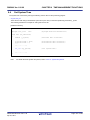
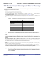
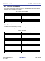
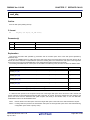
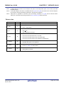
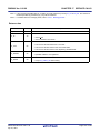
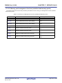
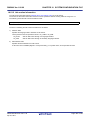
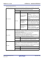
The following table lists the segment names prescribed in the RI850V4.
Section
Name
.kernel_syst
em
.kernel_info
Section
Attribute
RX
R
Section
Type
PROGBITS
PROGBITS
ROM/RAM
Description
ROM/RAM
Area where the RI850V4's core processing
part and main processing part of service
calls provided by the RI850V4 are to be
allocated.
ROM/RAM
Area where initial information items related
to OS resources that do not change
dynamically are allocated as system
information tables.
.kernel_data
RW
NOBITS
RAM
Area where the system stack, the task
stack, data queue, fixed-sized memory
pool and variable-sized memory pool are
to be allocated.
.kernel_con
st
RW
NOBITS
RAM
Area where the management objects
(system control block, task control bock,
etc.) are to be allocated.
R20UT0515EJ0100 Rev.1.00
Apr 01, 2011
Page 22 of 406
RI850V4 Ver.1.00.00
2.7
CHAPTER 2 SYSTEM CONSTRUCTION
Creating Load Module
Run a build on CubeSuite+ for files created in sections from "2.2 Coding of Target-Dependent Module" to "2.6 Coding
Directive File", and library files provided by the RI850V4 and C compiler package, to create a load module.
1 ) Create or load a project
Create a new project, or load an existing one.
Note
See RI Series Start User's Manual or CubeSuite+ Start User's Manual for details about creating a new
project or loading an existing one.
2 ) Set a build target project
When making settings for or running a build, set the active project.
If there is no subproject, the project is always active.
Note
See CubeSuite+ V850 Build / CubeSuite+ Build for CX Compiler User's Manual for details about setting
the active project.
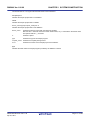
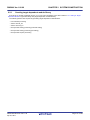
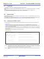
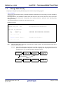
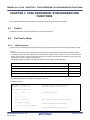
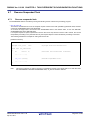
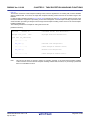
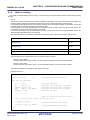
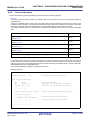
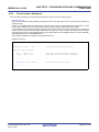
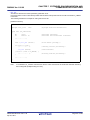
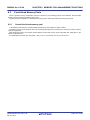
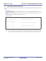
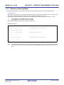
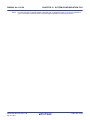
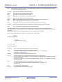
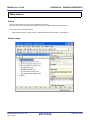
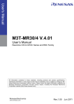
3 ) Confirm the version
Select the Realtime OS node on the project tree to open the Property panel.
Confirm the version of RI850V4 to be used in the [Kernel version] property on the [RI850V4] tab.
Figure 2-2 Property Panel: [RI850V4] Tab
4 ) Set build target files
For the project, add or remove build target files and update the dependencies.
Note
See CubeSuite+ V850 Build / CubeSuite+ Build for CX Compiler User's Manual for details about adding or
removing build target files for the project and updating the dependencies.
The following lists the files required for creating a load module.
- Library files created in "2.2.1 Creating target-dependent module library"
- Target-dependent module library
- C/assembly language source files created in "2.3 Coding Processing Programs"
- Processing programs (tasks, task exception handling routines, cyclic handlers, interrupt handlers, extended
service call routines, CPU exception handlers)
- System configuration file created in "2.4 Coding System Configuration File"
- SYSTEM CONFIGURATION FILE
R20UT0515EJ0100 Rev.1.00
Apr 01, 2011
Page 23 of 406
RI850V4 Ver.1.00.00
Note
CHAPTER 2 SYSTEM CONSTRUCTION
Specify "cfg" as the extention of the system configuration file name.If the extension is different, "cfg" is
automatically added (for example, if you designate "aaa.c" as a file name, the file is named as
"aaa.c.cfg").
- C/assembly language source files created in "2.5 Coding User-Own Coding Module"
- User-own coding module (initialization routine, idle routine, boot processing)
- Link directive file created in "2.6 Coding Directive File"
- Link directive file
- Library files provided by the RI850V4
- Kernel library
- Library files provided by the C compiler package
- Standard library, runtime library, etc.
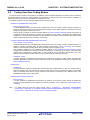
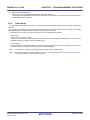
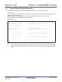
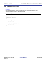
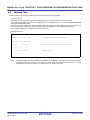
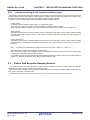
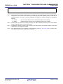
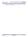
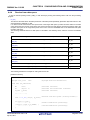
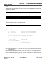
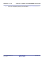
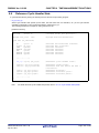
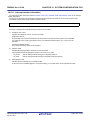
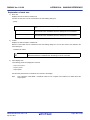
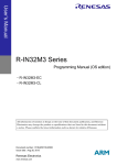
Note 1
If the system configuration file is added to the Project Tree panel, the Realtime OS generated files node is
appeared.
The following information files are appeared under the Realtime OS generated files node. However, these
files are not generated at this point in time.
- System information table file
- System information header file
- Entry file
Figure 2-3 Project Tree Panel (After Adding sys.cfg)
Note 2
When replacing the system configuration file, first remove the added system configuration file from the
project, then add another one again.
R20UT0515EJ0100 Rev.1.00
Apr 01, 2011
Page 24 of 406
RI850V4 Ver.1.00.00
Note 3
CHAPTER 2 SYSTEM CONSTRUCTION
Although it is possible to add more than one system configuration files to a project, only the first file added
is enabled. Note that if you remove the enabled file from the project, the remaining additional files will not
be enabled; you must therefore add them again.
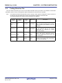
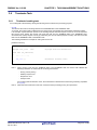
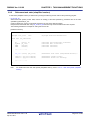
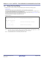
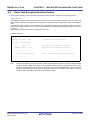
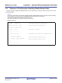
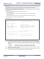
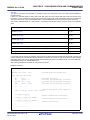
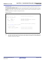
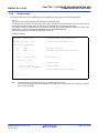
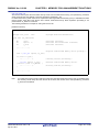
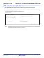
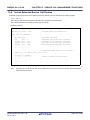
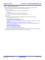
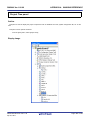
5 ) Set the output of information files
Select the system configuration file on the project tree to open the Property panel.
On the [System Configuration File Related Information] tab, set the output of information files (system information
table file, system information header file, and entry file).
Figure 2-4 Property Panel: [System Configuration File Related Information] Tab
6 ) Specify the output of a load module file
Set the output of a load module file as the product of the build.
Note
See CubeSuite+ V850 Build / CubeSuite+ Build for CX Compiler User's Manual for details about
specifying the output of a load module file.
7 ) Set build options
Set the options for the compiler, assembler, linker, and the like.
Note
See CubeSuite+ V850 Build / CubeSuite+ Build for CX Compiler User's Manual for details about setting
build options.
R20UT0515EJ0100 Rev.1.00
Apr 01, 2011
Page 25 of 406
RI850V4 Ver.1.00.00
CHAPTER 2 SYSTEM CONSTRUCTION
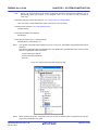
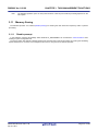
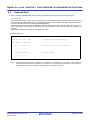
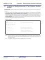
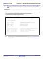
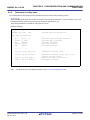
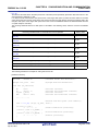
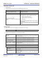
8 ) Run a build
Run a build to create a load module.
Note
See CubeSuite+ V850 Build / CubeSuite+ Build for CX Compiler User's Manual for details about runnig a
build.
Figure 2-5 Project Tree Panel (After Running Build)
9 ) Save the project
Save the setting information of the project to the project file.
Note
See CubeSuite+ Start User's Manual for details about saving the project.
R20UT0515EJ0100 Rev.1.00
Apr 01, 2011
Page 26 of 406
RI850V4 Ver.1.00.00
CHAPTER 3 TASK MANAGEMENT FUNCTIONS
CHAPTER 3 TASK MANAGEMENT FUNCTIONS
This chapter describes the task management functions performed by the RI850V4.
3.1
Outline
The task management functions provided by the RI850V4 include a function to reference task statuses such as priorities
and detailed task information, in addition to a function to manipulate task statuses such as generation, activation and
termination of tasks.
3.2
Tasks
A task is processing program that is not executed unless it is explicitly manipulated via service calls provided by the
RI850V4, unlike other processing programs (cyclic handler and interrupt handler), and is called from the scheduler.
The RI850V4 manages the states in which each task may enter and tasks themselves, by using management objects
(task management blocks) corresponding to tasks one-to-one.
Note
3.2.1
The execution environment information required for a task's execution is called "task context". During task
execution switching, the task context of the task currently under execution by the RI850V4 is saved and the
task context of the next task to be executed is loaded.
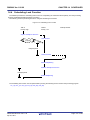
Task state
Tasks enter various states according to the acquisition status for the OS resources required for task execution and the
occurrence/non-occurrence of various events. In this process, the current state of each task must be checked and
managed by the RI850V4.
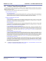
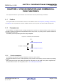
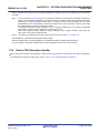
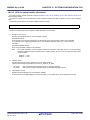
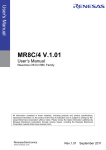
The RI850V4 classifies task states into the following six types.
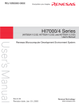
Figure 3-1 Task State
READY state
RUNNING state
WAITING state
WAITING-SUSPENDED state
SUSPENDED state
DORMANT state
R20UT0515EJ0100 Rev.1.00
Apr 01, 2011
Page 27 of 406
RI850V4 Ver.1.00.00
CHAPTER 3 TASK MANAGEMENT FUNCTIONS
1 ) DORMANT state
State of a task that is not active, or the state entered by a task whose processing has ended.
A task in the DORMANT state, while being under management of the RI850V4, is not subject to RI850V4 scheduling.
2 ) READY state
State of a task for which the preparations required for processing execution have been completed, but since another
task with a higher priority level or a task with the same priority level is currently being processed, the task is waiting
to be given the CPU's use right.
3 ) RUNNING state
State of a task that has acquired the CPU use right and is currently being processed.
Only one task can be in the running state at one time in the entire system.
4 ) WAITING state
State in which processing execution has been suspended because conditions required for execution are not
satisfied.
Resumption of processing from the WAITING state starts from the point where the processing execution was
suspended. The value of information required for resumption (such as task context) immediately before suspension
is therefore restored.
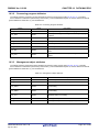
In the RI850V4, the WAITING state is classified into the following ten types according to their required conditions
and managed.
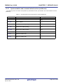
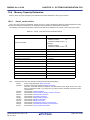
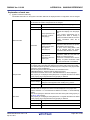
Table 3-1 WAITING State
WAITING State
Description
Sleeping state
A task enters this state if the counter for the task (registering the
number of times the wakeup request has been issued) indicates 0x0
upon the issuance of a slp_tsk or tslp_tsk.
Delayed state
A task enters this state upon the issuance of a dly_tsk.
WAITING state for a semaphore
resource
A task enters this state if it cannot acquire a resource from the
relevant semaphore upon the issuance of a wai_sem or twai_sem.
WAITING state for an eventflag
A task enters this state if a relevant eventflag does not satisfy a
predetermined condition upon the issuance of a wai_flg or twai_flg.
Sending WAITING state for a
data queue
A task enters this state if cannot send a data to the relevant data
queue upon the issuance of a snd_dtq or tsnd_dtq.
Receiving WAITING state for a
data queue
A task enters this state if cannot receive a data from the relevant
data queue upon the issuance of a rcv_dtq or trcv_dtq.
Receiving WAITING state for a
mailbox
A task enters this state if cannot receive a message from the
relevant mailbox upon the issuance of a rcv_mbx or trcv_mbx.
WAITING state for a mutex
A task enters this state if cannot lock the relevant mutex upon the
issuance of a loc_mtx or tloc_mtx.
WAITING state for a fixed-sized
memory block
A task enters this state if it cannot acquire a fixed-sized memory
block from the relevant fixed-sized memory pool upon the issuance
of a get_mpf or tget_mpf.
WAITING state for a variablesized memory block
A task enters this state if it cannot acquire a variable-sized memory
block from the relevant variable-sized memory pool upon the
issuance of a get_mpl or tget_mpl.
5 ) SUSPENDED state
State in which processing execution has been suspended forcibly.
Resumption of processing from the SUSPENDED state starts from the point where the processing execution was
suspended. The value of information required for resumption (such as task context) immediately before suspension
is therefore restored.
R20UT0515EJ0100 Rev.1.00
Apr 01, 2011
Page 28 of 406
RI850V4 Ver.1.00.00
CHAPTER 3 TASK MANAGEMENT FUNCTIONS
6 ) WAITING-SUSPENDED state
State in which the WAITING and SUSPENDED states are combined.
A task enters the SUSPENDED state when the WAITING state is cancelled, or enters the WAITING state when the
SUSPENDED state is cancelled.
3.2.2
Task priority
A priority level that determines the order in which that task will be processed in relation to the other tasks is assigned to
each task.
As a result, in the RI850V4, the task that has the highest priority level of all the tasks that have entered an executable
state (RUNNING state or READY state) is selected and given the CPU use right.
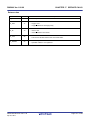
In the RI850V4, the following two types of priorities are used for management purposes.
- Initial priority
Priority set when a task is created.
Therefore, the priority level of a task (priority level referenced by the scheduler) immediately after it moves from the
DORMANT state to the READY state is the initial priority.
- Current priority
Priority referenced by the RI850V4 when it performs a manipulation (task scheduling, queuing tasks to a wait queue in
the order of priority, or priority level inheritance) when a task is activated.
Note 1
In the RI850V4, a task having a smaller priority number is given a higher priority.
Note 2
The priority range that can be specified in a system can be defined in Basic information (Maximum priority:
maxpri) when creating a system configuration file.
R20UT0515EJ0100 Rev.1.00
Apr 01, 2011
Page 29 of 406
RI850V4 Ver.1.00.00
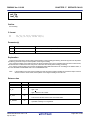
3.2.3
CHAPTER 3 TASK MANAGEMENT FUNCTIONS
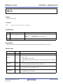
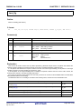
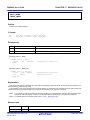
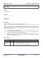
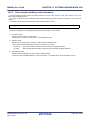
Basic form of tasks
When coding a task, use a void function with one VP_INT argument (any function name is fine).
The extended information specified with Task information, or the start code specified when sta_tsk or ista_tsk is issued,
is set for the exinf argument.
The following shows the basic form of tasks in C.
[CA850/CX version]
#include
<kernel.h>
#pragma rtos_task
task
/*Standard header file definition*/
/*#pragma directive definition*/
void task (VP_INT exinf)
{
/* ......... */
ext_tsk ();
/*Terminate invoking task*/
}
[CCV850/CCV850E version]
#include
<kernel.h>
/*Standard header file definition*/
void task (VP_INT exinf)
{
/* ......... */
ext_tsk ();
/*Terminate invoking task*/
}
Note 1
If a task moves from the DORMANT state to the READY state by issuing sta_tsk or ista_tsk, the start code
specified when issuing sta_tsk or ista_tsk is set to the exinf argument.
Note 2
When the return instruction is issued in a task, the same processing as ext_tsk is performed.
Note 3
For details about the extended information, refer to "3.4 Activate Task".
R20UT0515EJ0100 Rev.1.00
Apr 01, 2011
Page 30 of 406
RI850V4 Ver.1.00.00
3.2.4
CHAPTER 3 TASK MANAGEMENT FUNCTIONS
Internal processing of task
In the RI850V4, original dispatch processing (task scheduling) is executed during task switching.
Therefore, note the following points when coding tasks.
- Coding method
Code tasks using C or assembly language.
When coding in C, they can be coded in the same manner as ordinary functions coded.
When coding in assembly language, code them according to the calling rules prescribed in the compiler used.
- Stack switching
When switching tasks, the RI850V4 performs switching to the task specified in Task information.
- Service call issuance
Service calls that can be issued in tasks are limited to the service calls that can be issued from tasks.
- Acknowledgment of maskable interrupts (the ID flag of PSW)
When processing is started (a task changes from DORMANT to RUNNING status, and control transitions to the task
process), the maskable-interrupt acknowledgement status differs depending on the initial interrupt status set in the
Task information attributes.
It is possible to change the maskable interrupt acknowledgement status from inside a process. The changed status is
not passed on when control shifts to the processing program after the task process ends (the task status changes
from RUNNING to DORMANT).
When a process resumes (a task status changes from RUNNING to READY, WAITING, WAITING-SUSPENDED, or
SUSPENDED, and then back to RUNNING, and control shifts to the task), the maskable interrupt acknowledgement
status is returned to the status it had before it was stopped.
Note
For details on the valid issuance range of each service call, refer to Table 17-1 to Table 17-14.
R20UT0515EJ0100 Rev.1.00
Apr 01, 2011
Page 31 of 406
RI850V4 Ver.1.00.00
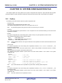
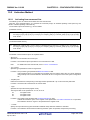
3.3
CHAPTER 3 TASK MANAGEMENT FUNCTIONS
Creat Task
In the RI850V4, the method of creating a task is limited to "static creation".
Tasks therefore cannot be created dynamically using a method such as issuing a service call from a processing
program.
Static task creation means defining of tasks using static API "CRE_TSK" in the system configuration file.
For details about the static API "CRE_TSK", refer to "18.5.1 Task information".
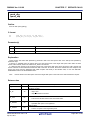
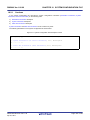
3.4
Activate Task
The RI850V4 provides two types of interfaces for task activation: queuing an activation request queuing and not
queuing an activation request.
In the RI850V4, extended information specified in Task information during configuration and the value specified for the
second parameter stacd when service call sta_tsk or ista_tsk is issued are called "extended information".
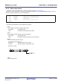
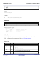
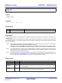
3.4.1
Queuing an activation request
A task (queuing an activation request) is activated by issuing the following service call from the processing program.
- act_tsk, iact_tsk
These service calls move a task specified by parameter tskid from the DORMANT state to the READY state.
As a result, the target task is queued at the end on the ready queue corresponding to the initial priority and becomes
subject to scheduling by the RI850V4.
If the target task has been moved to a state other than the DORMANT state when this service call is issued, this
service call does not move the state but increments the activation request counter (by added 0x1 to the wakeup
request counter).
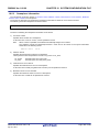
The following describes an example for coding this service call.
[CA850/CX version]
#include
<kernel.h>
#pragma rtos_task
task
void task (VP_INT exinf)
{
ID
tskid = 8;
/*Standard header file definition*/
/*#pragma directive definition*/
/*Declares and initializes variable*/
/* ......... */
act_tsk (tskid);
/*Avtivate task (queues an activation request)*/
/* ......... */
}
Note 1
The activation request counter managed by the RI850V4 is configured in 7-bit widths. If the number of
activation requests exceeds the maximum count value 127 as a result of issuing this service call, the counter
manipulation processing is therefore not performed but "E_QOVR" is returned.
Note 2
Extended information specified in Task information is passed to the task activated by issuing these service
calls.
R20UT0515EJ0100 Rev.1.00
Apr 01, 2011
Page 32 of 406
RI850V4 Ver.1.00.00
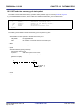
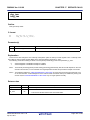
3.4.2
CHAPTER 3 TASK MANAGEMENT FUNCTIONS
Not queuing an activation request
A task (not queuing an activation request) is activated by issuing the following service call from the processing program.
- sta_tsk, ista_tsk
These service calls move a task specified by parameter tskid from the DORMANT state to the READY state.
As a result, the target task is queued at the end on the ready queue corresponding to the initial priority and becomes
subject to scheduling by the RI850V4.
This service call does not perform queuing of activation requests. If the target task is in a state other than the
DORMANT state, the status manipulation processing for the target task is therefore not performed but "E_OBJ" is
returned.
Specify for parameter stacd the extended information transferred to the target task.
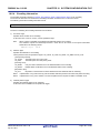
The following describes an example for coding this service call.
[CA850/CX version]
#include
<kernel.h>
#pragma rtos_task
task
void task (VP_INT exinf)
{
ID
tskid = 8;
VP_INT stacd = 123;
/*Standard header file definition*/
/*#pragma directive definition*/
/*Declares and initializes variable*/
/*Declares and initializes variable*/
/* ......... */
sta_tsk (tskid, stacd);
/*Activate task (does not queue an activation */
/*request)*/
/* ......... */
}
R20UT0515EJ0100 Rev.1.00
Apr 01, 2011
Page 33 of 406
RI850V4 Ver.1.00.00
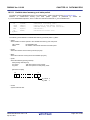
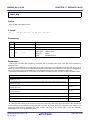
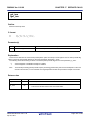
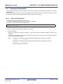
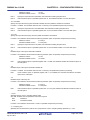
3.5
CHAPTER 3 TASK MANAGEMENT FUNCTIONS
Cancel Task Activation Requests
An activation request is cancelled by issuing the following service call from the processing program.
- can_act, ican_act
This service call cancels all of the activation requests queued to the task specified by parameter tskid (sets the
activation request counter to 0x0).
When this service call is terminated normally, the number of cancelled activation requests is returned.
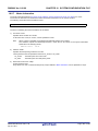
The following describes an example for coding this service call.
[CA850/CX version]
#include
<kernel.h>
#pragma rtos_task
task
void task (VP_INT exinf)
{
ER_UINT ercd;
ID
tskid = 8;
/*Standard header file definition*/
/*#pragma directive definition*/
/*Declares variable*/
/*Declares and initializes variable*/
/* ......... */
ercd = can_act (tskid);
/*Cancel task activation requests*/
if (ercd >= 0x0) {
/* ......... */
}
/*Normal termination processing*/
/* ......... */
}
Note
This service call does not perform status manipulation processing but performs the setting of activation
request counter. Therefore, the task does not move from a state such as the READY state to the DORMANT
state.
R20UT0515EJ0100 Rev.1.00
Apr 01, 2011
Page 34 of 406
RI850V4 Ver.1.00.00
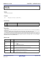
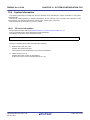
3.6
CHAPTER 3 TASK MANAGEMENT FUNCTIONS
Terminate Task
3.6.1
Terminate invoking task
An invoking task is terminated by issuing the following service call from the processing program.
- ext_tsk
This service call moves an invoking task from the RUNNING state to the DORMANT state.
As a result, the invoking task is unlinked from the ready queue and excluded from the RI850V4 scheduling subject.
If an activation request has been queued to the invoking task (the activation request counter is not set to 0x0) when
this service call is issued, this service call moves the task from the RUNNING state to the DORMANT state,
decrements the wakeup request counter (by subtracting 0x1 from the wakeup request counter), and then moves the
task from the DORMANT state to the READY state.
The following describes an example for coding this service call.
[CA850/CX version]
#include
<kernel.h>
#pragma rtos_task
task
/*Standard header file definition*/
/*#pragma directive definition*/
void task (VP_INT exinf)
{
/* ......... */
ext_tsk ();
/*Terminate invoking task*/
}
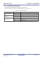
Note 1
When moving a task from the RUNNING state to the DORMANT state, this service call initializes the
following information to values that are set during task creation.
- Priority (current priority)
- Wakeup request count
- Suspension count
- Interrupt status
If an invoking task has locked a mutex, the locked state is released at the same time (processing equivalent
to unl_mtx).
Note 2
When the return instruction is issued in a task, the same processing as ext_tsk is performed.
R20UT0515EJ0100 Rev.1.00
Apr 01, 2011
Page 35 of 406
RI850V4 Ver.1.00.00
3.6.2
CHAPTER 3 TASK MANAGEMENT FUNCTIONS
Terminate task
Other tasks are forcibly terminated by issuing the following service call from the processing program.
- ter_tsk
This service call forcibly moves a task specified by parameter tskid to the DORMANT state.
As a result, the target task is excluded from the RI850V4 scheduling subject.
If an activation request has been queued to the target task (the activation request counter is not set to 0x0) when this
service call is issued, this service call moves the task to the DORMANT state, decrements the wakeup request
counter (by subtracting 0x1 from the wakeup request counter), and then moves the task from the DORMANT state to
the READY state.
The following describes an example for coding this service call.
[CA850/CX version]
#include
<kernel.h>
#pragma rtos_task
task
void task (VP_INT exinf)
{
ID
tskid = 8;
/*Standard header file definition*/
/*#pragma directive definition*/
/*Declares and initializes variable*/
/* ......... */
ter_tsk (tskid);
/*Terminate task*/
/* ......... */
}
Note
When moving a task to the DORMANT state, this service call initializes the following information to values
that are set during task creation.
- Priority (current priority)
- Wakeup request count
- Suspension count
- Interrupt status
If the target task has locked a mutex, the locked state is released at the same time (processing equivalent to
unl_mtx).
R20UT0515EJ0100 Rev.1.00
Apr 01, 2011
Page 36 of 406
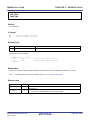
RI850V4 Ver.1.00.00
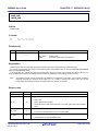
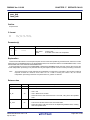
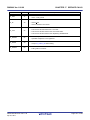
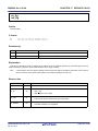
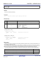
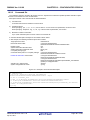
3.7
CHAPTER 3 TASK MANAGEMENT FUNCTIONS
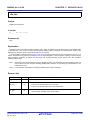
Change Task Priority
The priority is changed by issuing the following service call from the processing program.
- chg_pri, ichg_pri
These service calls change the priority of the task specified by parameter tskid (current priority) to a value specified by
parameter tskpri.
If the target task is in the RUNNING or READY state after this service call is issued, this service call re-queues the
task at the end of the ready queue corresponding to the priority specified by parameter tskpri, following priority
change processing.
The following describes an example for coding this service call.
[CA850/CX version]
#include
<kernel.h>
#pragma rtos_task
/*Standard header file definition*/
task
/*#pragma directive definition*/
void task (VP_INT exinf)
{
ID
tskid = 8;
PRI
tskpri = 9;
/*Declares and initializes variable*/
/*Declares and initializes variable*/
/* ......... */
chg_pri (tskid, tskpri);
/*Change task priority*/
/* ......... */
}
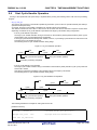
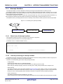
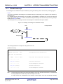
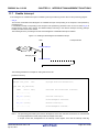
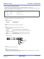
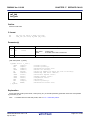
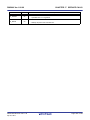
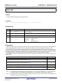
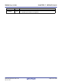
Note
When the target task is queued to a wait queue in the order of priority, the wait order may change due to
issuance of this service call.
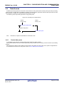
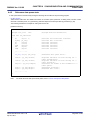
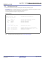
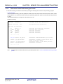
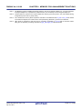
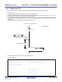
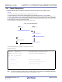
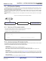
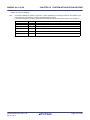
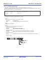
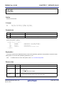
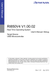
Example
When three tasks (task A: priority level 10, task B: priority level 11, task C: priority level 12) are
queued to the semaphore wait queue in the order of priority, and the priority level of task B is
changed from 11 to 9, the wait order will be changed as follows.
Semaphore
Task A
Priority: 10
Task B
Priority: 11
Task C
Priority: 12
Task A
Priority: 10
Task C
Priority: 12
chg_pri (Task B, 9);
Semaphore
R20UT0515EJ0100 Rev.1.00
Apr 01, 2011
Task B
Priority: 9
Page 37 of 406
RI850V4 Ver.1.00.00
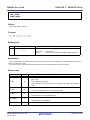
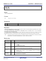
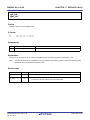
3.8
CHAPTER 3 TASK MANAGEMENT FUNCTIONS
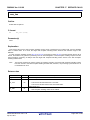
Reference Task Priority
A task priority is referenced by issuing the following service call from the processing program.
- get_pri, iget_pri
Stores current priority of the task specified by parameter tskid in the area specified by parameter p_tskpri.
The following describes an example for coding this service call.
[CA850/CX version]
#include
<kernel.h>
#pragma rtos_task
task
void task (VP_INT exinf)
{
ID
tskid = 8;
PRI
p_tskpri;
/*Standard header file definition*/
/*#pragma directive definition*/
/*Declares and initializes variable*/
/*Declares variable*/
/* ......... */
get_pri (tskid, &p_tskpri);
/*Reference task priority*/
/* ......... */
}
R20UT0515EJ0100 Rev.1.00
Apr 01, 2011
Page 38 of 406
RI850V4 Ver.1.00.00
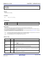
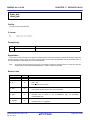
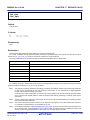
3.9
CHAPTER 3 TASK MANAGEMENT FUNCTIONS
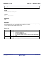
Reference Task State
3.9.1
Reference task state
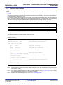
A task status is referenced by issuing the following service call from the processing program.
- ref_tsk, iref_tsk
Stores task state packet (current state, current priority, etc.) of the task specified by parameter tskid in the area
specified by parameter pk_rtsk.
The following describes an example for coding this service call.
[CA850/CX version]
#include
<kernel.h>
#pragma rtos_task
task
void task (VP_INT exinf)
{
ID
tskid = 8;
T_RTSK pk_rtsk;
STAT
tskstat;
PRI
tskpri;
STAT
tskwait;
ID
wobjid;
TMO
lefttmo;
UINT
actcnt;
UINT
wupcnt;
UINT
suscnt;
ATR
tskatr;
PRI
itskpri;
/*Standard header file definition*/
/*#pragma directive definition*/
/*Declares
/*Declares
/*Declares
/*Declares
/*Declares
/*Declares
/*Declares
/*Declares
/*Declares
/*Declares
/*Declares
/*Declares
and initializes variable*/
data structure*/
variable*/
variable*/
variable*/
variable*/
variable*/
variable*/
variable*/
variable*/
variable*/
variable*/
/* ......... */
ref_tsk (tskid, &pk_rtsk);
/*Reference task state*/
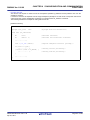
tskstat = pk_rtsk.tskstat;
tskpri = pk_rtsk.tskpri;
tskwait = pk_rtsk.tskwait;
wobjid = pk_rtsk.wobjid;
/*Reference current state*/
/*Reference current priority*/
/*Reference reason for waiting*/
/*Reference object ID number for which the */
/*task is waiting*/
/*Reference remaining time until timeout*/
/*Reference activation request count*/
/*Reference wakeup request count*/
/*Reference suspension count*/
/*Reference attribute*/
/*Reference initial priority*/
lefttmo = pk_rtsk.lefttmo;
actcnt = pk_rtsk.actcnt;
wupcnt = pk_rtsk.wupcnt;
suscnt = pk_rtsk.suscnt;
tskatr = pk_rtsk.tskatr;
itskpri = pk_rtsk.itskpri;
/* ......... */
}
Note
For details about the task state packet, refer to "16.2.1 Task state packet".
R20UT0515EJ0100 Rev.1.00
Apr 01, 2011
Page 39 of 406
RI850V4 Ver.1.00.00
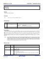
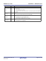
3.9.2
CHAPTER 3 TASK MANAGEMENT FUNCTIONS
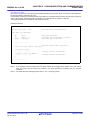
Reference task state (simplified version)
A task status (simplified version) is referenced by issuing the following service call from the processing program.
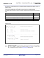
- ref_tst, iref_tst
Stores task state packet (current state, reason for waiting) of the task specified by parameter tskid in the area
specified by parameter pk_rtst.
Used for referencing only the current state and reason for wait among task information.
Response becomes faster than using ref_tsk or iref_tsk because only a few information items are acquired.
The following describes an example for coding this service call.
[CA850/CX version]
#include
<kernel.h>
#pragma rtos_task
task
void task (VP_INT exinf)
{
ID
tskid = 8;
T_RTST pk_rtst;
STAT
tskstat;
STAT
tskwait;
/*Standard header file definition*/
/*#pragma directive definition*/
/*Declares
/*Declares
/*Declares
/*Declares
and initializes variable*/
data structure*/
variable*/
variable*/
/* ......... */
ref_tst (tskid, &pk_rtst);
/*Reference task state (simplified version)*/
tskstat = pk_rtst.tskstat;
tskwait = pk_rtst.tskwait;
/*Reference current state*/
/*Reference reason for waiting*/
/* ......... */
}
Note
For details about the task state packet (simplified version), refer to "16.2.2 Task state packet (simplified
version)".
R20UT0515EJ0100 Rev.1.00
Apr 01, 2011
Page 40 of 406
RI850V4 Ver.1.00.00
3.10
CHAPTER 3 TASK MANAGEMENT FUNCTIONS
Target-Dependent Module
To support various execution environments, the RI850V4 extracts processing performed when a stack required by the
RI850V4 or the processing program to perform execution overflows, from the memory pool management function, as a
target-dependent module. This prevents inadvertent program loops in the system caused by a stack overflow.
Note
3.10.1
The RI850V4 checks the stack overflow only when TA_ON (overflow is checked) is defined in Basic
information during configuration.
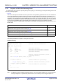
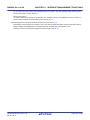
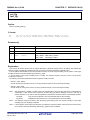
Post-overflow processing
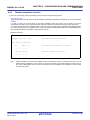
This is a routine dedicated to post-overflow processing, which is extracted as a target-dependent module, for executing
post processing when a stack required by the RI850V4 or the processing program to perform execution overflows. It is
called from the RI850V4 when a stack overflows.
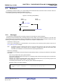
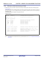
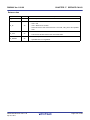
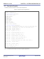
- Basic form of post-overflow processing
Code post-overflow processing by using the void type function (function name: _kernel_stk_overflow) that has two
INT type arguments.
The "value of stack pointer sp when a stack overflow is detected" is set to argument r6, and the "value of program
counter pc when a stack overflow is detected" is set to argument r7.
The following shows the basic form of coding post-overflow processing in assembly language.
[CA850/CX version, CCV850/CCV850E version]
#include
<kernel.h>
/*Standard header file definition*/
.text
.align 0x4
.globl __kernel_stk_overflow
__kernel_stk_overflow :
/* ......... */
.halt_loop :
jbr
.halt_loop
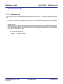
- Processing performed during post-overflow processing
Post-overflow processing is a routine dedicated to post processing, which is extracted as a target-dependent module,
for executing post processing when a stack required by the RI850V4 or the processing program to perform execution
overflows. Therefore, note the following points when coding post-overflow processing.
- Coding method
Code post-overflow processing using C or assembly language.
When coding in C, they can be coded in the same manner as ordinary functions coded.
When coding in assembly language, code them according to the calling rules prescribed in the compiler used.
- Stack switching
The RI850V4 does not perform the processing related to stack switching when passing control to post-overflow
processing.
When using the system stack specified in Basic information, the code regarding stack switching must therefore
be written in post-overflow processing.
- Service call issuance
Issuance of service calls is prohibited during post-overflow processing because the normal operation cannot be
guaranteed.
The following lists processing that should be executed in post-overflow processing.
- Post-processing that handles stack overflows
R20UT0515EJ0100 Rev.1.00
Apr 01, 2011
Page 41 of 406
RI850V4 Ver.1.00.00
Note
3.11
CHAPTER 3 TASK MANAGEMENT FUNCTIONS
The detailed operations (such as reset) that should be coded as post-overflow processing depends on the
user system.
Memory Saving
The RI850V4 provides the method (Disable preempt) for reducing the task stack size required by tasks to perform
processing.
3.11.1
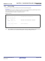
Disable preempt
In the RI850V4, preempt acknowledge status attribute TA_DISPREEMPT can be defined in Task information when
creating a system configuration file.
The task for which this attribute is defined performs the operation that continues processing by ignoring the scheduling
request issued from a non-task, so a management area of 24 to 44 bytes can be reduced per task.
R20UT0515EJ0100 Rev.1.00
Apr 01, 2011
Page 42 of 406
RI850V4 Ver.1.00.00 CHAPTER 4 TASK DEPENDENT SYNCHRONIZATION FUNCTIONS
CHAPTER 4 TASK DEPENDENT SYNCHRONIZATION
FUNCTIONS
This chapter describes the task dependent synchronization functions performed by the RI850V4.
4.1
Outline
The RI850V4 provides several task-dependent synchronization functions.
4.2
Put Task to Sleep
4.2.1
Waiting forever
A task is moved to the sleeping state (waiting forever) by issuing the following service call from the processing program.
- slp_tsk
As a result, the invoking task is unlinked from the ready queue and excluded from the RI850V4 scheduling subject.
If a wakeup request has been queued to the target task (the wakeup request counter is not set to 0x0) when this
service call is issued, this service call does not move the state but decrements the wakeup request counter (by
subtracting 0x1 from the wakeup request counter).
The sleeping state is cancelled in the following cases, and then moved to the READY state.
Sleeping State Cancel Operation
Return Value
A wakeup request was issued as a result of issuing wup_tsk.
E_OK
A wakeup request was issued as a result of issuing iwup_tsk.
E_OK
Forced release from waiting (accept rel_wai while waiting).
E_RLWAI
Forced release from waiting (accept irel_wai while waiting).
E_RLWAI
The following describes an example for coding this service call.
[CA850/CX version]
#include
<kernel.h>
#pragma rtos_task
task
/*Standard header file definition*/
/*#pragma directive definition*/
void task (VP_INT exinf)
{
ER
ercd;
/*Declares variable*/
/* ......... */
ercd = slp_tsk ();
if (ercd == E_OK) {
/* ......... */
} else if (ercd == E_RLWAI) {
/* ......... */
}
R20UT0515EJ0100 Rev.1.00
Apr 01, 2011
/*Put task to sleep (waiting forever)*/
/*Normal termination processing*/
/*Forced termination processing*/
Page 43 of 406
RI850V4 Ver.1.00.00 CHAPTER 4 TASK DEPENDENT SYNCHRONIZATION FUNCTIONS
/* ......... */
}
R20UT0515EJ0100 Rev.1.00
Apr 01, 2011
Page 44 of 406
RI850V4 Ver.1.00.00 CHAPTER 4 TASK DEPENDENT SYNCHRONIZATION FUNCTIONS
4.2.2
With timeout
A task is moved to the sleeping state (with timeout) by issuing the following service call from the processing program.
- tslp_tsk
This service call moves an invoking task from the RUNNING state to the WAITING state (sleeping state).
As a result, the invoking task is unlinked from the ready queue and excluded from the RI850V4 scheduling subject.
If a wakeup request has been queued to the target task (the wakeup request counter is not set to 0x0) when this
service call is issued, this service call does not move the state but decrements the wakeup request counter (by
subtracting 0x1 from the wakeup request counter).
The sleeping state is cancelled in the following cases, and then moved to the READY state.
Sleeping State Cancel Operation
Return Value
A wakeup request was issued as a result of issuing wup_tsk.
E_OK
A wakeup request was issued as a result of issuing iwup_tsk.
E_OK
Forced release from waiting (accept rel_wai while waiting).
E_RLWAI
Forced release from waiting (accept irel_wai while waiting).
E_RLWAI
Polling failure or timeout.
E_TMOUT
The following describes an example for coding this service call.
[CA850/CX version]
#include
<kernel.h>
#pragma rtos_task
task
void task (VP_INT exinf)
{
ER
ercd;
TMO
tmout = 3600;
/*Standard header file definition*/
/*#pragma directive definition*/
/*Declares variable*/
/*Declares and initializes variable*/
/* ......... */
ercd = tslp_tsk (tmout);
/*Put task to sleep (with timeout)*/
if (ercd == E_OK) {
/* ......... */
} else if (ercd == E_RLWAI)
/* ......... */
} else if (ercd == E_TMOUT)
/* ......... */
}
/*Normal termination processing*/
{
/*Forced termination processing*/
{
/*Timeout processing*/
/* ......... */
}
Note
When TMO_FEVR is specified for wait time tmout, processing equivalent to slp_tsk will be executed.
R20UT0515EJ0100 Rev.1.00
Apr 01, 2011
Page 45 of 406
RI850V4 Ver.1.00.00 CHAPTER 4 TASK DEPENDENT SYNCHRONIZATION FUNCTIONS
4.3
Wakeup Task
A task is woken up by issuing the following service call from the processing program.
- wup_tsk, iwup_tsk
These service calls cancel the WAITING state (sleeping state) of the task specified by parameter tskid.
As a result, the target task is moved from the sleeping state to the READY state, or from the WAITING-SUSPENDED
state to the SUSPENDED state.
If the target task is in a state other than the sleeping state when this service call is issued, this service call does not
move the state but increments the wakeup request counter (by added 0x1 to the wakeup request counter).
The following describes an example for coding this service call.
[CA850/CX version]
#include
<kernel.h>
#pragma rtos_task
task
void task (VP_INT exinf)
{
ID
tskid = 8;
/*Standard header file definition*/
/*#pragma directive definition*/
/*Declares and initializes variable*/
/* ......... */
wup_tsk (tskid);
/*Wakeup task*/
/* ......... */
}
Note
The wakeup request counter managed by the RI850V4 is configured in 7-bit widths. If the number of wakeup
requests exceeds the maximum count value 127 as a result of issuing this service call, the counter
manipulation processing is therefore not performed but "E_QOVR" is returned.
R20UT0515EJ0100 Rev.1.00
Apr 01, 2011
Page 46 of 406
RI850V4 Ver.1.00.00 CHAPTER 4 TASK DEPENDENT SYNCHRONIZATION FUNCTIONS
4.4
Cancel Task Wakeup Requests
A wakeup request is cancelled by issuing the following service call from the processing program.
- can_wup, ican_wup
These service calls cancel all of the wakeup requests queued to the task specified by parameter tskid (the wakeup
request counter is set to 0x0).
When this service call is terminated normally, the number of cancelled wakeup requests is returned.
The following describes an example for coding this service call.
[CA850/CX version]
#include
<kernel.h>
#pragma rtos_task
task
void task (VP_INT exinf)
{
ER_UINT ercd;
ID
tskid = 8;
/*Standard header file definition*/
/*#pragma directive definition*/
/*Declares variable*/
/*Declares and initializes variable*/
/* ......... */
ercd = can_wup (tskid);
/*Cancel task wakeup requests*/
if (ercd >= 0x0) {
/* ......... */
}
/*Normal termination processing*/
/* ......... */
}
R20UT0515EJ0100 Rev.1.00
Apr 01, 2011
Page 47 of 406
RI850V4 Ver.1.00.00 CHAPTER 4 TASK DEPENDENT SYNCHRONIZATION FUNCTIONS
4.5
Release Task from Waiting
The WAITING state is forcibly cancelled by issuing the following service call from the processing program.
- rel_wai, irel_wai
These service calls forcibly cancel the WAITING state of the task specified by parameter tskid.
As a result, the target task unlinked from the wait queue and is moved from the WAITING state to the READY state, or
from the WAITING-SUSPENDED state to the SUSPENDED state.
"E_RLWAI" is returned from the service call that triggered the move to the WAITING state (slp_tsk, wai_sem, or the
like) to the task whose WAITING state is cancelled by this service call.
The following describes an example for coding this service call.
[CA850/CX version]
#include
<kernel.h>
#pragma rtos_task
task
void task (VP_INT exinf)
{
ID
tskid = 8;
/*Standard header file definition*/
/*#pragma directive definition*/
/*Declares and initializes variable*/
/* ......... */
rel_wai (tskid);
/*Release task from waiting*/
/* ......... */
}
Note 1
This service call does not perform queuing of forced cancellation requests. If the target task is in a state
other than the WAITING or WAITING-SUSPENDED state, "E_OBJ" is returned.
Note 2
The SUSPENDED state is not cancelled by these service calls.
R20UT0515EJ0100 Rev.1.00
Apr 01, 2011
Page 48 of 406
RI850V4 Ver.1.00.00 CHAPTER 4 TASK DEPENDENT SYNCHRONIZATION FUNCTIONS
4.6
Suspend Task
A task is moved to the SUSPENDED state by issuing the following service call from the processing program.
- sus_tsk, isus_tsk
These service calls add 0x1 to the suspend request counter for the task specified by parameter tskid, and then move
the target task from the RUNNING state to the SUSPENDED state, from the READY state to the SUSPENDED state,
or from the WAITING state to the WAITING-SUSPENDED state.
If the target task has moved to the SUSPENDED or WAITING-SUSPENDED state when this service call is issued, the
counter manipulation processing is not performed but only the suspend request counter increment processing is
executed.
The following describes an example for coding this service call.
[CA850/CX version]
#include
<kernel.h>
#pragma rtos_task
task
void task (VP_INT exinf)
{
ID
tskid = 8;
/*Standard header file definition*/
/*#pragma directive definition*/
/*Declares and initializes variable*/
/* ......... */
sus_tsk (tskid);
/*Suspend task*/
/* ......... */
}
Note
The suspend request counter managed by the RI850V4 is configured in 7-bit widths. If the number of
suspend requests exceeds the maximum count value 127 as a result of issuing this service call, the counter
manipulation processing is therefore not performed but "E_QOVR" is returned.
R20UT0515EJ0100 Rev.1.00
Apr 01, 2011
Page 49 of 406
RI850V4 Ver.1.00.00 CHAPTER 4 TASK DEPENDENT SYNCHRONIZATION FUNCTIONS
4.7
Resume Suspended Task
4.7.1
Resume suspended task
The SUSPENDED state is cancelled by issuing the following service call from the processing program.
- rsm_tsk, irsm_tsk
This service call subtracts 0x1 from the suspend request counter for the task specified by parameter tskid, and then
cancels the SUSPENDED state of the target task.
As a result, the target task is moved from the SUSPENDED state to the READY state, or from the WAITINGSUSPENDED state to the WAITING state.
If a suspend request is queued (subtraction result is other than 0x0) when this service call is issued, the counter
manipulation processing is not performed but only the suspend request counter decrement processing is executed.
The following describes an example for coding this service call.
[CA850/CX version]
#include
<kernel.h>
#pragma rtos_task
task
void task (VP_INT exinf)
{
ID
tskid = 8;
/*Standard header file definition*/
/*#pragma directive definition*/
/*Declares and initializes variable*/
/* ......... */
rsm_tsk (tskid);
/*Resume suspended task*/
/* ......... */
}
Note
This service call does not perform queuing of cancellation requests. If the target task is in a state other than
the SUSPENDED or WAITING-SUSPENDED state, "E_OBJ" is therefore returned.
R20UT0515EJ0100 Rev.1.00
Apr 01, 2011
Page 50 of 406
RI850V4 Ver.1.00.00 CHAPTER 4 TASK DEPENDENT SYNCHRONIZATION FUNCTIONS
4.7.2
Forcibly resume suspended task
The SUSPENDED state is forcibly cancelled by issuing the following service calls from the processing program.
- frsm_tsk, ifrsm_tsk
These service calls cancel all of the suspend requests issued for the task specified by parameter tskid (by setting the
suspend request counter to 0x0). As a result, the target task moves from the SUSPENDED state to the READY state,
or from the WAITING-SUSPENDED state to the WAITING state.
The following describes an example for coding this service call.
[CA850/CX version]
#include
<kernel.h>
#pragma rtos_task
task
void task (VP_INT exinf)
{
ID
tskid = 8;
/*Standard header file definition*/
/*#pragma directive definition*/
/*Declares and initializes variable*/
/* ......... */
frsm_tsk (tskid);
/*Forcibly resume suspended task*/
/* ......... */
}
Note
This service call does not perform queuing of cancellation requests. If the target task is in a state other than
the SUSPENDED or WAITING-SUSPENDED state, "E_OBJ" is therefore returned.
R20UT0515EJ0100 Rev.1.00
Apr 01, 2011
Page 51 of 406
RI850V4 Ver.1.00.00 CHAPTER 4 TASK DEPENDENT SYNCHRONIZATION FUNCTIONS
4.8
Delay Task
A task is moved to the delayed state by issuing the following service call from the processing program.
- dly_tsk
This service call moves the invoking task from the RUNNING state to the WAITING state (delayed state).
As a result, the invoking task is unlinked from the ready queue and excluded from the RI850V4 scheduling subject.
The delayed state is cancelled in the following cases, and then moved to the READY state.
Delayed State Cancel Operation
Return Value
Delay time specified by parameter dlytim has elapsed.
E_OK
Forced release from waiting (accept rel_wai while waiting).
E_RLWAI
Forced release from waiting (accept irel_wai while waiting).
E_RLWAI
The following describes an example for coding this service call.
[CA850/CX version]
#include
<kernel.h>
#pragma rtos_task
task
void task (VP_INT exinf)
{
ER
ercd;
RELTIM dlytim = 3600;
/*Standard header file definition*/
/*#pragma directive definition*/
/*Declares variable*/
/*Declares and initializes variable*/
/* ......... */
ercd = dly_tsk (dlytim);
if (ercd == E_OK) {
/* ......... */
} else if (ercd == E_RLWAI) {
/* ......... */
}
/*Delay task*/
/*Normal termination processing*/
/*Forced termination processing*/
/* ......... */
}
R20UT0515EJ0100 Rev.1.00
Apr 01, 2011
Page 52 of 406
RI850V4 Ver.1.00.00 CHAPTER 4 TASK DEPENDENT SYNCHRONIZATION FUNCTIONS
4.9
Differences Between Wakeup Wait with Timeout and Time Elapse
Wait
Wakeup waits with timeout and time elapse waits differ on the following points.
Table 4-1 Differences Between Wakeup Wait with Timeout and Time Elapse Wait
Wakeup Wait with Timeout
Time Elapse Wait
Service call that causes status change
tslp_tsk
dly_tsk
Return value when timed out
E_TMOUT
E_OK
Operation when wup_tsk or iwup_tsk
is issued
Wakeup
Queues the wakeup request (time
elapse wait is not cancelled).
R20UT0515EJ0100 Rev.1.00
Apr 01, 2011
Page 53 of 406
RI850V4 Ver.1.00.00
CHAPTER 5 TASK EXCEPTION HANDLING FUNCTIONS
CHAPTER 5 TASK EXCEPTION HANDLING FUNCTIONS
This chapter describes the task exception handling functions performed by the RI850V4.
5.1
Outline
The task exception handling functions of the RI850V4 include a function related to the task exception handling routine
that is activated when a task exception handling request is issued (function for manipulating or referencing the task
exception handling routine status).
5.2
Task Exception Handling Routines
The task exception handling routine is a routine dedicated to task exception handling, and is activated when a task
exception handling request is issued.
The RI850V4 positions task exception handling routines as extensions of the task for which a task exception handling
request is issued. A task exception handling routine is therefore activated when the task for which a task exception
handling request is issued moves to the RUNNING state.
The RI850V4 manages the states in which each task exception handling routine may enter and task exception handling
routines themselves, by using management objects (task exception handling routines contained in task management
blocks) corresponding to task exception handling routines one-to-one.
Note
5.2.1
Task exception handling is enabled when a task exception handling routine is activated.
Basic form of task exception handling routines
Code task exception handling routines by using the void type function that has one TEXPTN type argument and one
VP_INT type argument.
The "task exception code specified when a task exception handling request (ras_tex or iras_tex) is issued" is set to
argument rasptn, and "extended information specified in Task information" is set to argument exinf.
The following shows the basic form of task exception handling routines in C.
[CA850/CX version, CCV850/CCV850E version]
#include
<kernel.h>
/*Standard header file definition*/
void texrtn (TEXPTN rasptn, VP_INT exinf)
{
/* ......... */
return;
/*Terminate task exception handling routine*/
}
Note
A task exception handling routine is activated when the task for which a task exception handling request was
issued moves to the RUNNING state. Due to this, the task exception handling request may be issued multiple
times from when the first task exception handling request is issued until the task exception handling routine is
activated.
To handle such a case, the RI850V4 sets "OR of all the task exception codes" issued from when the first task
exception handling request is issued until the task exception handling routine is activated, to argument rasptn
of the task exception handling routine.
R20UT0515EJ0100 Rev.1.00
Apr 01, 2011
Page 54 of 406
RI850V4 Ver.1.00.00
5.2.2
CHAPTER 5 TASK EXCEPTION HANDLING FUNCTIONS
Internal processing of task exception handling routine
The RI850V4 executes the original task exception pre-processing when passing control from the task for which a task
exception handling request was issued to a task exception handling routine, as well as the original task exception postprocessing when returning control from the task exception handling routine to the task.
Therefore, note the following points when coding task exception handling routines.
- Coding method
Code task exception handling routines using C or assembly language.
When coding in C, they can be coded in the same manner as ordinary functions coded.
When coding in assembly language, code them according to the calling rules prescribed in the compiler used.
- Stack switching
The RI850V4 positions task exception handling routines as extensions of the task for which a task exception handling
request is issued. When passing control to a task exception handling routine, stack switching processing is therefore
not performed.
- Service call issuance
The RI850V4 positions task exception handling routines as extensions of the task for which a task exception handling
request is issued. In task exception handling routines, therefore, only "service calls that can be issued in the task" can
be issued.
Note
For details on the valid issuance range of each service call, refer to Table 17-1 to Table 17-14.
- Acknowledgment of maskable interrupts (the ID flag of PSW)
When the process starts, the maskable interrupt acknowledgement status is inherited from the task status
corresponding to the task exception handling routine.
It is possible to change the maskable interrupt acknowledgement status from inside a process. The changed status is
passed on to the task corresponding to the task exception handling routine.
5.3
Define Task Exception Handling Routine
The RI850V4 supports the static registration of task exception handling routines only. They cannot be registered
dynamically by issuing a service call from the processing program.
Static task exception handling routine registration means defining of task exception handling routines using static API
"DEF_TEX" in the system configuration file.
For details about the static API "DEF_TEX", refer to "18.5.2 Task exception handling routine information".
R20UT0515EJ0100 Rev.1.00
Apr 01, 2011
Page 55 of 406
RI850V4 Ver.1.00.00
5.4
CHAPTER 5 TASK EXCEPTION HANDLING FUNCTIONS
Raise Task Exception Handling Routine
A task exception handling routine is activated by issuing the following service call from the processing program.
- ras_tex, iras_tex
These service calls issue a task exception handling request for the task specified by parameter tskid. As a result, the
task exception handling routine registered to the target task is activated when the target task moves to the RUNNING
state.
For parameter rasptn, specify the task exception code to be passed to the target task exception handling routine. The
target task exception handling routine can then be manipulatable by handling the task exception code as a function
parameter.
The following describes an example for coding this service call.
[CA850/CX version]
#include
<kernel.h>
#pragma rtos_task
task
void task (VP_INT exinf)
{
ID
tskid = 8;
TEXPTN rasptn = 123;
/*Standard header file definition*/
/*#pragma directive definition*/
/*Declares and initializes variable*/
/*Declares and initializes variable*/
/* ......... */
ras_tex (tskid, rasptn);
/*Raise task exception handling routine*/
/* ......... */
}
Note
These service calls do not perform queuing of task exception handling requests. If a task exception handling
request is issued multiple times before a task exception handling routine is activated (from when a task
exception handling request is issued until the target task moves to the RUNNING state), the task exception
handling request will not be issued after the second and later issuance of these service calls, but the task
exception code is just held pending (OR of task exception codes).
R20UT0515EJ0100 Rev.1.00
Apr 01, 2011
Page 56 of 406
RI850V4 Ver.1.00.00
5.5
CHAPTER 5 TASK EXCEPTION HANDLING FUNCTIONS
Disabling and Enabling Activation of Task Exception Handling
Routines
Activation of task exception handling routines is disabled or enabled by issuing the following service call from the
processing program.
- dis_tex
This service call moves a task exception handling routine, which is registered to an invoking task, from the enabled
state to disabled state. As a result, the target task exception handling routine is excluded from the activation targets of
the RI850V4 from when this service call is issued until ena_tex is issued.
If a task exception handling request (ras_tex or iras_tex) is issued from when this service call is issued until ena_tex
is issued, the RI850V4 only performs processing such as acknowledgment of task exception handling requests and
the actual activation processing is delayed until the target task exception handling routine moves to the task exception
handling enabled state.
The following describes an example for coding this service call.
[CA850/CX version]
#include
<kernel.h>
#pragma rtos_task
task
/*Standard header file definition*/
/*#pragma directive definition*/
void task (VP_INT exinf)
{
/* ......... */
dis_tex ();
/*Disable task exceptions*/
/* ......... */
/*Task exception disable state*/
ena_tex ();
/*Enable task exceptions*/
/* ......... */
/*Task exception enable state*/
}
Note 1
This service call does not perform queuing of disable requests. If the target task exception handling routine
has been moved to the task exception handling disabled state, therefore, no processing is performed but it is
not handled as an error.
Note 2
In the RI850V4, task exception handling is disabled when a task is activated.
R20UT0515EJ0100 Rev.1.00
Apr 01, 2011
Page 57 of 406
RI850V4 Ver.1.00.00
CHAPTER 5 TASK EXCEPTION HANDLING FUNCTIONS
- ena_tex
This service call moves a task exception handling routine, which is registered to an invoking task, from the disabled
state to enabled state. As a result, the target task exception handling routine becomes the activation target of the
RI850V4.
If a task exception handling request (ras_tex or iras_tex) is issued from when dis_tex is issued until this service call is
issued, the RI850V4 only performs processing such as acknowledgment of task exception handling requests and the
actual activation processing is delayed until the target task exception handling routine moves to the task exception
handling enabled state.
The following describes an example for coding this service call.
[CA850/CX version]
#include
<kernel.h>
#pragma rtos_task
task
/*Standard header file definition*/
/*#pragma directive definition*/
void task (VP_INT exinf)
{
/* ......... */
dis_tex ();
/*Disable task exceptions*/
/* ......... */
/*Task exception disable state*/
ena_tex ();
/*Enable task exceptions*/
/* ......... */
/*Task exception enable state*/
}
Note
This service call does not perform queuing of activation requests. If the target task exception handling
routine has been moved to the task exception handling enabled state, therefore, no processing is performed
but it is not handled as an error.
R20UT0515EJ0100 Rev.1.00
Apr 01, 2011
Page 58 of 406
RI850V4 Ver.1.00.00
5.6
CHAPTER 5 TASK EXCEPTION HANDLING FUNCTIONS
Reference Task Exception Handling Disable/Enable State
The task exception handling disable/enable state can be referenced by issuing the following service call from the
processing program.
- sns_tex
This service call acquires the state (task exception handling disabled/enabled state) of the task exception handling
routine registered to the task that is in the RUNNING state when this service call is issued.
The state of the task exception handling routine is returned.
The following describes an example for coding this service call.
[CA850/CX version]
#include
<kernel.h>
#pragma rtos_task
task
void task (VP_INT exinf)
{
BOOL
ercd;
/*Standard header file definition*/
/*#pragma directive definition*/
/*Declares variable*/
/* ......... */
ercd = sns_tex ();
if (ercd == TRUE) {
/* ......... */
} else if (ercd == FALSE) {
/* ......... */
}
/*Reference task exception handling state*/
/*Task exception disable state*/
/*Task exception enable state*/
/* ......... */
}
R20UT0515EJ0100 Rev.1.00
Apr 01, 2011
Page 59 of 406
RI850V4 Ver.1.00.00
5.7
CHAPTER 5 TASK EXCEPTION HANDLING FUNCTIONS
Reference Detailed Information of Task Exception Handling Routine
The detailed information of a task exception handling routine is referenced by issuing the following service call from the
processing program.
- ref_tex, iref_tex
These service calls store the detailed information (current status, pending exception code, etc.) of the task exception
handling routine registered to the task specified by parameter tskid into the area specified by parameter pk_rtex.
E_OBJ is returned if no task exception handling routines are registered to the specified task.
The following describes an example for coding this service call.
[CA850/CX version]
#include
<kernel.h>
#pragma rtos_task
task
void task (VP_INT exinf)
{
ID
tskid = 8;
T_RTEX pk_rtex;
STAT
texstat;
TEXPTN pndptn;
ATR
texatr;
/*Standard header file definition*/
/*#pragma directive definition*/
/*Declares
/*Declares
/*Declares
/*Declares
/*Declares
and initializes variable*/
data structure*/
variable*/
variable*/
variable*/
/* ......... */
ref_tex (tskid, &pk_rtex);
/*Reference task exception handling state*/
texstat = pk_rtex.texstat;
pndptn = pk_rtex.pndptn;
texatr = pk_rtex.texatr;
/*Reference current state*/
/*Reference pending exception code*/
/*Reference attribute*/
/* ......... */
}
Note
For details about the task exception handling routine state packet, refer to "16.2.3 Task exception handling
routine state packet".
R20UT0515EJ0100 Rev.1.00
Apr 01, 2011
Page 60 of 406
CHAPTER 6 SYNCHRONIZATION AND COMMUNICATION
FUNCTIONS
RI850V4 Ver.1.00.00
CHAPTER 6 SYNCHRONIZATION AND COMMUNICATION FUNCTIONS
This chapter describes the synchronization and communication functions performed by the RI850V4.
6.1
Outline
The synchronization and communication functions of the RI850V4 consist of Semaphores, Eventflags, Data Queues,
and Mailboxes that are provided as means for realizing exclusive control, queuing, and communication among tasks.
6.2
Semaphores
In the RI850V4, non-negative number counting semaphores are provided as a means (exclusive control function) for
preventing contention for limited resources (hardware devices, library function, etc.) arising from the required conditions of
simultaneously running tasks.
The following shows a processing flow when using a semaphore.
Figure 6-1 Processing Flow (Semaphore)
Task
Acquire semaphore resource
Exclusive control period
Release semaphore resource
6.2.1
Create semaphore
In the RI850V4, the method of creating a semaphore is limited to "static creation".
Semaphores therefore cannot be created dynamically using a method such as issuing a service call from a processing
program.
Static semaphore creation means defining of semaphores using static API "CRE_SEM" in the system configuration file.
For details about the static API "CRE_SEM", refer to "18.5.3 Semaphore information".
R20UT0515EJ0100 Rev.1.00
Apr 01, 2011
Page 61 of 406
CHAPTER 6 SYNCHRONIZATION AND COMMUNICATION
FUNCTIONS
RI850V4 Ver.1.00.00
6.2.2
Acquire semaphore resource
A resource is acquired (waiting forever, polling, or with timeout) by issuing the following service call from the processing
program.
- wai_sem
This service call acquires a resource from the semaphore specified by parameter semid (subtracts 0x1 from the
semaphore counter).
If no resources are acquired from the target semaphore when this service call is issued (no available resources exist),
this service call does not acquire resources but queues the invoking task to the target semaphore wait queue and
moves it from the RUNNING state to the WAITING state (resource acquisition wait state).
The WAITING state for a semaphore resource is cancelled in the following cases, and then moved to the READY
state.
WAITING State for a Semaphore Resource Cancel Operation
Return Value
The resource was returned to the target semaphore as a result of issuing sig_sem.
E_OK
The resource was returned to the target semaphore as a result of issuing isig_sem.
E_OK
Forced release from waiting (accept rel_wai while waiting).
E_RLWAI
Forced release from waiting (accept irel_wai while waiting).
E_RLWAI
The following describes an example for coding this service call.
[CA850/CX version]
#include
<kernel.h>
#pragma rtos_task
task
void task (VP_INT exinf)
{
ER
ercd;
ID
semid = 1;
/*Standard header file definition*/
/*#pragma directive definition*/
/*Declares variable*/
/*Declares and initializes variable*/
/* ......... */
ercd = wai_sem (semid);
/*Acquire semaphore resource (waiting forever)*/
if (ercd == E_OK) {
/* ......... */
/*Normal termination processing*/
} else if (ercd == E_RLWAI) {
/* ......... */
/*Forced termination processing*/
}
/* ......... */
}
Note
Invoking tasks are queued to the target semaphore wait queue in the order defined during configuration
(FIFO order or priority order).
R20UT0515EJ0100 Rev.1.00
Apr 01, 2011
Page 62 of 406
CHAPTER 6 SYNCHRONIZATION AND COMMUNICATION
FUNCTIONS
RI850V4 Ver.1.00.00
- pol_sem, ipol_sem
This service call acquires a resource from the semaphore specified by parameter semid (subtracts 0x1 from the
semaphore counter).
If a resource could not be acquired from the target semaphore (semaphore counter is set to 0x0) when this service
call is issued, the counter manipulation processing is not performed but "E_TMOUT" is returned.
The following describes an example for coding this service call.
[CA850/CX version]
#include
<kernel.h>
#pragma rtos_task
task
void task (VP_INT exinf)
{
ER
ercd;
ID
semid = 1;
/*Standard header file definition*/
/*#pragma directive definition*/
/*Declares variable*/
/*Declares and initializes variable*/
/* ......... */
ercd = pol_sem (semid);
if (ercd == E_OK) {
/* ......... */
} else if (ercd == E_TMOUT) {
/* ......... */
}
/*Acquire semaphore resource (polling)*/
/*Polling success processing*/
/*Polling failure processing*/
/* ......... */
}
R20UT0515EJ0100 Rev.1.00
Apr 01, 2011
Page 63 of 406
CHAPTER 6 SYNCHRONIZATION AND COMMUNICATION
FUNCTIONS
RI850V4 Ver.1.00.00
- twai_sem
This service call acquires a resource from the semaphore specified by parameter semid (subtracts 0x1 from the
semaphore counter).
If no resources are acquired from the target semaphore when service call is issued this (no available resources exist),
this service call does not acquire resources but queues the invoking task to the target semaphore wait queue and
moves it from the RUNNING state to the WAITING state with timeout (resource acquisition wait state).
The WAITING state for a semaphore resource is cancelled in the following cases, and then moved to the READY
state.
WAITING State for a Semaphore Resource Cancel Operation
Return Value
The resource was returned to the target semaphore as a result of issuing sig_sem.
E_OK
The resource was returned to the target semaphore as a result of issuing isig_sem.
E_OK
Forced release from waiting (accept rel_wai while waiting).
E_RLWAI
Forced release from waiting (accept irel_wai while waiting).
E_RLWAI
Polling failure or timeout.
E_TMOUT
The following describes an example for coding this service call.
[CA850/CX version]
#include
<kernel.h>
#pragma rtos_task
task
void task (VP_INT exinf)
{
ER
ercd;
ID
semid = 1;
TMO
tmout = 3600;
/*Standard header file definition*/
/*#pragma directive definition*/
/*Declares variable*/
/*Declares and initializes variable*/
/*Declares and initializes variable*/
/* ......... */
ercd = twai_sem (semid, tmout); /*Acquire semaphore resource (with timeout)*/
if (ercd == E_OK) {
/* ......... */
} else if (ercd == E_RLWAI) {
/* ......... */
} else if (ercd == E_TMOUT) {
/* ......... */
}
/*Normal termination processing*/
/*Forced termination processing*/
/*Timeout processing*/
/* ......... */
}
Note 1
Invoking tasks are queued to the target semaphore wait queue in the order defined during configuration
(FIFO order or priority order).
Note 2
TMO_FEVR is specified for wait time tmout, processing equivalent to wai_sem will be executed. When
TMO_POL is specified, processing equivalent to pol_sem /ipol_sem will be executed.
R20UT0515EJ0100 Rev.1.00
Apr 01, 2011
Page 64 of 406
CHAPTER 6 SYNCHRONIZATION AND COMMUNICATION
FUNCTIONS
RI850V4 Ver.1.00.00
6.2.3
Release semaphore resource
A resource is returned by issuing the following service call from the processing program.
- sig_sem, isig_sem
These service calls return the resource to the semaphore specified by parameter semid (adds 0x1 to the semaphore
counter).
If a task is queued in the wait queue of the target semaphore when this service call is issued, the counter
manipulation processing is not performed but the resource is passed to the relevant task (first task of wait queue).
As a result, the relevant task is unlinked from the wait queue and is moved from the WAITING state (WAITING state
for a semaphore resource) to the READY state, or from the WAITING-SUSPENDED state to the SUSPENDED state.
The following describes an example for coding this service call.
[CA850/CX version]
#include
<kernel.h>
#pragma rtos_task
task
void task (VP_INT exinf)
{
ID
semid = 1;
/*Standard header file definition*/
/*#pragma directive definition*/
/*Declares and initializes variable*/
/* ......... */
sig_sem (semid);
/*Release semaphore resource*/
/* ......... */
}
Note
With the RI850V4, the maximum possible number of semaphore resources (maximum resource count) is
defined during configuration. If the number of resources exceeds the specified maximum resource count,
this service call therefore does not return the acquired resources (addition to the semaphore counter value)
but returns E_QOVR.
R20UT0515EJ0100 Rev.1.00
Apr 01, 2011
Page 65 of 406
CHAPTER 6 SYNCHRONIZATION AND COMMUNICATION
FUNCTIONS
RI850V4 Ver.1.00.00
6.2.4
Reference semaphore state
A semaphore status is referenced by issuing the following service call from the processing program.
- ref_sem, iref_sem
Stores semaphore state packet (ID number of the task at the head of the wait queue, current resource count, etc.) of
the semaphore specified by parameter semid in the area specified by parameter pk_rsem.
The following describes an example for coding this service call.
[CA850/CX version]
#include
<kernel.h>
#pragma rtos_task
task
void task (VP_INT exinf)
{
ID
semid = 1;
T_RSEM pk_rsem;
ID
wtskid;
UINT
semcnt;
ATR
sematr;
UINT
maxsem;
/*Standard header file definition*/
/*#pragma directive definition*/
/*Declares
/*Declares
/*Declares
/*Declares
/*Declares
/*Declares
and initializes variable*/
data structure*/
variable*/
variable*/
variable*/
variable*/
/* ......... */
ref_sem (semid, &pk_rsem);
/*Reference semaphore state*/
wtskid = pk_rsem.wtskid;
/*Reference ID number of the task at the */
/*head of the wait queue*/
/*Reference current resource count*/
/*Reference attribute*/
/*Reference maximum resource count*/
semcnt = pk_rsem.semcnt;
sematr = pk_rsem.sematr;
maxsem = pk_rsem.maxsem;
/* ......... */
}
Note
For details about the semaphore state packet, refer to "16.2.4 Semaphore state packet".
R20UT0515EJ0100 Rev.1.00
Apr 01, 2011
Page 66 of 406
CHAPTER 6 SYNCHRONIZATION AND COMMUNICATION
FUNCTIONS
RI850V4 Ver.1.00.00
6.3
Eventflags
The RI850V4 provides 32-bit eventflags as a queuing function for tasks, such as keeping the tasks waiting for execution,
until the results of the execution of a given processing program are output.
The following shows a processing flow when using an eventflag.
Figure 6-2 Processing Flow (Eventflag)
Task A
Priority: High
Task B
Priority: Low
Wait for eventflag
Queuing period
Set eventflag
6.3.1
Create eventflag
In the RI850V4, the method of creating an eventflag is limited to "static creation".
Eventflags therefore cannot be created dynamically using a method such as issuing a service call from a processing
program.
Static event flag creation means defining of event flags using static API "CRE_FLG" in the system configuration file.
For details about the static API "CRE_FLG", refer to "18.5.4 Eventflag information".
R20UT0515EJ0100 Rev.1.00
Apr 01, 2011
Page 67 of 406
CHAPTER 6 SYNCHRONIZATION AND COMMUNICATION
FUNCTIONS
RI850V4 Ver.1.00.00
6.3.2
Set eventflag
bit pattern is set by issuing the following service call from the processing program.
- set_flg, iset_flg
These service calls set the result of ORing the bit pattern of the eventflag specified by parameter flgid and the bit
pattern specified by parameter setptn as the bit pattern of the target eventflag.
If the required condition of the task queued to the target eventflag wait queue is satisfied when this service call is
issued, the relevant task is unlinked from the wait queue at the same time as bit pattern setting processing.
As a result, the relevant task is moved from the WAITING state (WAITING state for an eventflag) to the READY state,
or from the WAITING-SUSPENDED state to the SUSPENDED state.
The following describes an example for coding this service call.
[CA850/CX version]
#include
<kernel.h>
#pragma rtos_task
task
void task (VP_INT exinf)
{
ID
flgid = 1;
FLGPTN setptn = 10;
/*Standard header file definition*/
/*#pragma directive definition*/
/*Declares and initializes variable*/
/*Declares and initializes variable*/
/* ......... */
set_flg (flgid, setptn);
/*Set eventflag*/
/* ......... */
}
Note
If the bit pattern set to the target eventflag is B'1100 and the bit pattern specified by parameter setptn is
B'1010 when this service call is issued, the bit pattern of the target eventflag is set to B'1110.
R20UT0515EJ0100 Rev.1.00
Apr 01, 2011
Page 68 of 406
CHAPTER 6 SYNCHRONIZATION AND COMMUNICATION
FUNCTIONS
RI850V4 Ver.1.00.00
6.3.3
Clear eventflag
A bit pattern is cleared by issuing the following service call from the processing program.
- clr_flg, iclr_flg
This service call sets the result of ANDing the bit pattern set to the eventflag specified by parameter flgid and the bit
pattern specified by parameter clrptn as the bit pattern of the target eventflag.
The following describes an example for coding this service call.
[CA850/CX version]
#include
<kernel.h>
#pragma rtos_task
task
void task (VP_INT exinf)
{
ID
flgid = 1;
FLGPTN clrptn = 10;
/*Standard header file definition*/
/*#pragma directive definition*/
/*Declares and initializes variable*/
/*Declares and initializes variable*/
/* ......... */
clr_flg (flgid, clrptn);
/*Clear eventflag*/
/* ......... */
}
Note
If the bit pattern set to the target eventflag is B'1100 and the bit pattern specified by parameter clrptn is
B'1010 when this service call is issued, the bit pattern of the target eventflag is set to B'1110.
R20UT0515EJ0100 Rev.1.00
Apr 01, 2011
Page 69 of 406
CHAPTER 6 SYNCHRONIZATION AND COMMUNICATION
FUNCTIONS
RI850V4 Ver.1.00.00
6.3.4
Wait for eventflag
A bit pattern is checked (waiting forever, polling, or with timeout) by issuing the following service call from the processing
program.
- wai_flg
This service call checks whether the bit pattern specified by parameter waiptn and the bit pattern that satisfies the
required condition specified by parameter wfmode are set to the eventflag specified by parameter flgid.
If a bit pattern that satisfies the required condition has been set for the target eventflag, the bit pattern of the target
eventflag is stored in the area specified by parameter p_flgptn.
If the bit pattern of the target eventflag does not satisfy the required condition when this service call is issued, the
invoking task is queued to the target eventflag wait queue.
As a result, the invoking task is unlinked from the ready queue and is moved from the RUNNING state to the
WAITING state (WAITING state for an eventflag).
The WAITING state for an eventflag is cancelled in the following cases, and then moved to the READY state.
WAITING State for an Eventflag Cancel Operation
Return Value
A bit pattern that satisfies the required condition was set to the target eventflag as a result of
issuing set_flg.
E_OK
A bit pattern that satisfies the required condition was set to the target eventflag as a result of
issuing iset_flg.
E_OK
Forced release from waiting (accept rel_wai while waiting).
E_RLWAI
Forced release from waiting (accept irel_wai while waiting).
E_RLWAI
The following shows the specification format of required condition wfmode.
- wfmode = TWF_ANDW
Checks whether all of the bits to which 1 is set by parameter waiptn are set as the target eventflag.
- wfmode = TWF_ORW
Checks which bit, among bits to which 1 is set by parameter waiptn, is set as the target eventflag.
The following describes an example for coding this service call.
[CA850/CX version]
#include
<kernel.h>
#pragma rtos_task
/*Standard header file definition*/
task
void task (VP_INT exinf)
{
ER
ercd;
ID
flgid = 1;
FLGPTN waiptn = 14;
MODE
wfmode = TWF_ANDW;
FLGPTN p_flgptn;
/*#pragma directive definition*/
/*Declares
/*Declares
/*Declares
/*Declares
/*Declares
variable*/
and initializes variable*/
and initializes variable*/
and initializes variable*/
variable*/
/* ......... */
/*Wait for eventflag (waiting forever)*/
ercd = wai_flg (flgid, waiptn, wfmode, &p_flgptn);
if (ercd == E_OK) {
/* ......... */
} else if (ercd == E_RLWAI) {
/* ......... */
}
R20UT0515EJ0100 Rev.1.00
Apr 01, 2011
/*Normal termination processing*/
/*Forced termination processing*/
Page 70 of 406
RI850V4 Ver.1.00.00
CHAPTER 6 SYNCHRONIZATION AND COMMUNICATION
FUNCTIONS
/* ......... */
}
Note 1
With the RI850V4, whether to enable queuing of multiple tasks to the event flag wait queue is defined during
configuration. If this service call is issued for the event flag (TW_WSGL attribute) to which a wait task is
queued, therefore, "E_ILUSE" is returned regardless of whether the required condition is immediately
satisfied.
TA_WSGL:
TA_WMUL:
Only one task is allowed to be in the WAITING state for the eventflag.
Multiple tasks are allowed to be in the WAITING state for the eventflag.
Note 2
Invoking tasks are queued to the target event flag (TA_WMUL attribute) wait queue in the order defined
during configuration (FIFO order or priority order).
Note 3
The RI850V4 performs bit pattern clear processing (0x0 setting) when the required condition of the target
eventflag (TA_CLR attribute) is satisfied.
Note 4
If the WAITING state for an eventflag is forcibly released by issuing rel_wai or irel_wai, the contents of the
area specified by parameter p_flgptn will be undefined.
R20UT0515EJ0100 Rev.1.00
Apr 01, 2011
Page 71 of 406
CHAPTER 6 SYNCHRONIZATION AND COMMUNICATION
FUNCTIONS
RI850V4 Ver.1.00.00
- pol_flg, ipol_flg
This service call checks whether the bit pattern specified by parameter waiptn and the bit pattern that satisfies the
required condition specified by parameter wfmode are set to the eventflag specified by parameter flgid.
If the bit pattern that satisfies the required condition has been set to the target eventflag, the bit pattern of the target
eventflag is stored in the area specified by parameter p_flgptn.
If the bit pattern of the target eventflag does not satisfy the required condition when this service call is issued,
"E_TMOUT" is returned.
The following shows the specification format of required condition wfmode.
- wfmode = TWF_ANDW
Checks whether all of the bits to which 1 is set by parameter waiptn are set as the target eventflag.
- wfmode = TWF_ORW
Checks which bit, among bits to which 1 is set by parameter waiptn, is set as the target eventflag.
The following describes an example for coding this service call.
[CA850/CX version]
#include
<kernel.h>
#pragma rtos_task
/*Standard header file definition*/
task
void task (VP_INT exinf)
{
ER
ercd;
ID
flgid = 1;
FLGPTN waiptn = 14;
MODE
wfmode = TWF_ANDW;
FLGPTN p_flgptn;
/*#pragma directive definition*/
/*Declares
/*Declares
/*Declares
/*Declares
/*Declares
variable*/
and initializes variable*/
and initializes variable*/
and initializes variable*/
variable*/
/* ......... */
/*Wait for eventflag (polling)*/
ercd = pol_flg (flgid, waiptn, wfmode, &p_flgptn);
if (ercd == E_OK) {
/* ......... */
} else if (ercd == E_TMOUT) {
/* ......... */
}
/*Polling success processing*/
/*Polling failure processing*/
/* ......... */
}
Note 1
With the RI850V4, whether to enable queuing of multiple tasks to the event flag wait queue is defined during
configuration. If this service call is issued for the event flag (TW_WSGL attribute) to which a wait task is
queued, therefore, "E_ILUSE" is returned regardless of whether the required condition is immediately
satisfied.
TA_WSGL:
TA_WMUL:
Only one task is allowed to be in the WAITING state for the eventflag.
Multiple tasks are allowed to be in the WAITING state for the eventflag.
Note 2
The RI850V4 performs bit pattern clear processing (0x0 setting) when the required condition of the target
eventflag (TA_CLR attribute) is satisfied.
Note 3
If the bit pattern of the target event flag does not satisfy the required condition when this service call is
issued, the contents in the area specified by parameter p_flgptn become undefined.
R20UT0515EJ0100 Rev.1.00
Apr 01, 2011
Page 72 of 406
CHAPTER 6 SYNCHRONIZATION AND COMMUNICATION
FUNCTIONS
RI850V4 Ver.1.00.00
- twai_flg
This service call checks whether the bit pattern specified by parameter waiptn and the bit pattern that satisfies the
required condition specified by parameter wfmode are set to the eventflag specified by parameter flgid.
If a bit pattern that satisfies the required condition has been set for the target eventflag, the bit pattern of the target
eventflag is stored in the area specified by parameter p_flgptn.
If the bit pattern of the target eventflag does not satisfy the required condition when this service call is issued, the
invoking task is queued to the target eventflag wait queue.
As a result, the invoking task is unlinked from the ready queue and is moved from the RUNNING state to the
WAITING state (WAITING state for an eventflag).
The WAITING state for an eventflag is cancelled in the following cases, and then moved to the READY state.
WAITING State for an Eventflag Cancel Operation
Return Value
A bit pattern that satisfies the required condition was set to the target eventflag as a result of
issuing set_flg.
E_OK
A bit pattern that satisfies the required condition was set to the target eventflag as a result of
issuing iset_flg.
E_OK
Forced release from waiting (accept rel_wai while waiting).
E_RLWAI
Forced release from waiting (accept irel_wai while waiting).
E_RLWAI
Polling failure or timeout.
E_TMOUT
The following shows the specification format of required condition wfmode.
- wfmode = TWF_ANDW
Checks whether all of the bits to which 1 is set by parameter waiptn are set as the target eventflag.
- wfmode = TWF_ORW
Checks which bit, among bits to which 1 is set by parameter waiptn, is set as the target eventflag.
The following describes an example for coding this service call.
[CA850/CX version]
#include
<kernel.h>
#pragma rtos_task
task
void task (VP_INT exinf)
{
ER
ercd;
ID
flgid = 1;
FLGPTN waiptn = 14;
MODE
wfmode = TWF_ANDW;
FLGPTN p_flgptn;
TMO
tmout = 3600;
/*Standard header file definition*/
/*#pragma directive definition*/
/*Declares
/*Declares
/*Declares
/*Declares
/*Declares
/*Declares
variable*/
and initializes
and initializes
and initializes
variable*/
and initializes
variable*/
variable*/
variable*/
variable*/
/* ......... */
/*Wait for eventflag (with timeout)*/
ercd = twai_flg (flgid, waiptn, wfmode, &p_flgptn, tmout);
if (ercd == E_OK) {
/* ......... */
} else if (ercd == E_RLWAI) {
/* ......... */
} else if (ercd == E_TMOUT) {
/* ......... */
}
R20UT0515EJ0100 Rev.1.00
Apr 01, 2011
/*Normal termination processing*/
/*Forced termination processing*/
/*Timeout processing*/
Page 73 of 406
RI850V4 Ver.1.00.00
CHAPTER 6 SYNCHRONIZATION AND COMMUNICATION
FUNCTIONS
/* ......... */
}
Note 1
With the RI850V4, whether to enable queuing of multiple tasks to the event flag wait queue is defined during
configuration. If this service call is issued for the event flag (TW_WSGL attribute) to which a wait task is
queued, therefore, "E_ILUSE" is returned regardless of whether the required condition is immediately
satisfied.
TA_WSGL:
TA_WMUL:
Only one task is allowed to be in the WAITING state for the eventflag.
Multiple tasks are allowed to be in the WAITING state for the eventflag.
Note 2
Invoking tasks are queued to the target event flag (TA_WMUL attribute) wait queue in the order defined
during configuration (FIFO order or priority order).
Note 3
The RI850V4 performs bit pattern clear processing (0x0 setting) when the required condition of the target
eventflag (TA_CLR attribute) is satisfied.
Note 4
If the event flag wait state is cancelled because rel_wai or irel_wai was issued or the wait time elapsed, the
contents in the area specified by parameter p_flgptn become undefined.
Note 5
TMO_FEVR is specified for wait time tmout, processing equivalent to wai_flg will be executed. When
TMO_POL is specified, processing equivalent to pol_flg /ipol_flg will be executed.
R20UT0515EJ0100 Rev.1.00
Apr 01, 2011
Page 74 of 406
CHAPTER 6 SYNCHRONIZATION AND COMMUNICATION
FUNCTIONS
RI850V4 Ver.1.00.00
6.3.5
Reference eventflag state
An eventflag status is referenced by issuing the following service call from the processing program.
- ref_flg, iref_flg
Stores eventflag state packet (ID number of the task at the head of the wait queue, current bit pattern, etc.) of the
eventflag specified by parameter flgid in the area specified by parameter pk_rflg.
The following describes an example for coding this service call.
[CA850/CX version]
#include
<kernel.h>
#pragma rtos_task
task
void task (VP_INT exinf)
{
ID
flgid = 1;
T_RFLG pk_rflg;
ID
wtskid;
FLGPTN flgptn;
ATR
flgatr;
/*Standard header file definition*/
/*#pragma directive definition*/
/*Declares
/*Declares
/*Declares
/*Declares
/*Declares
and initializes variable*/
data structure*/
variable*/
variable*/
variable*/
/* ......... */
ref_flg (flgid, &pk_rflg);
/*Reference eventflag state*/
wtskid = pk_rflg.wtskid;
/*Reference ID number of the task at the */
/*head of the wait queue*/
/*Reference current bit pattern*/
/*Reference attribute*/
flgptn = pk_rflg.flgptn;
flgatr = pk_rflg.flgatr;
/* ......... */
}
Note
For details about the eventflag state packet, refer to "16.2.5 Eventflag state packet".
R20UT0515EJ0100 Rev.1.00
Apr 01, 2011
Page 75 of 406
CHAPTER 6 SYNCHRONIZATION AND COMMUNICATION
FUNCTIONS
RI850V4 Ver.1.00.00
6.4
Data Queues
Multitask processing requires the inter-task communication function (data transfer function) that reports the processing
result of a task to another task. The RI850V4 therefore provides the data queues that have the data queue area in which
data read/write is enabled for transferring the prescribed size of data.
The following shows a processing flow when using a data queue.
Figure 6-3 Processing Flow (Data Queue)
Task A
Priority: High
Task B
Priority: Low
Receive from data queue
Reception wait period
Send to data queue
Note
6.4.1
Data units of 4 bytes are transmitted or received at a time.
Create data queue
In the RI850V4, the method of creating a deta queue is limited to "static creation".
Data queues therefore cannot be created dynamically using a method such as issuing a service call from a processing
program.
Static data queue creation means defining of data queues using static API "CRE_DTQ" in the system configuration file.
For details about the static API "CRE_DTQ", refer to "18.5.5 Data queue information".
R20UT0515EJ0100 Rev.1.00
Apr 01, 2011
Page 76 of 406
CHAPTER 6 SYNCHRONIZATION AND COMMUNICATION
FUNCTIONS
RI850V4 Ver.1.00.00
6.4.2
Send to data queue
A data is transmitted by issuing the following service call from the processing program.
- snd_dtq
This service call writes data specified by parameter data to the data queue area of the data queue specified by
parameter dtqid.
If there is no available space for writing data in the data queue area of the target data queue when this service call is
issued, this service call does not write data but queues the invoking task to the transmission wait queue of the target
data queue and moves it from the RUNNING state to the WAITING state (data transmission wait state).
The sending WAITING state for a data queue is cancelled in the following cases, and then moved to the READY
state.
Sending WAITING State for a Data Queue Cancel Operation
Return Value
Available space was secured in the data queue area of the target data queue as a result of
issuing rcv_dtq.
E_OK
Available space was secured in the data queue area of the target data queue as a result of
issuing prcv_dtq.
E_OK
Available space was secured in the data queue area of the target data queue as a result of
issuing iprcv_dtq.
E_OK
Available space was secured in the data queue area of the target data queue as a result of
issuing trcv_dtq.
E_OK
Forced release from waiting (accept rel_wai while waiting).
E_RLWAI
Forced release from waiting (accept irel_wai while waiting).
E_RLWAI
If a task has been queued to the reception wait queue of the target data queue when this service call is issued, this
service call does not write data but transfers the data to the task. As a result, the task is unlinked from the reception
wait queue and moves from the WAITING state (data reception wait state) to the READY state, or from the WAITINGSUSPENDED state to the SUSPENDED state.
The following describes an example for coding this service call.
[CA850/CX version]
#include
<kernel.h>
#pragma rtos_task
task
void task (VP_INT exinf)
{
ER
ercd;
ID
dtqid = 1;
VP_INT data = 123;
/*Standard header file definition*/
/*#pragma directive definition*/
/*Declares variable*/
/*Declares and initializes variable*/
/*Declares and initializes variable*/
/* ......... */
ercd = snd_dtq (dtqid, data);
if (ercd == E_OK) {
/* ......... */
} else if (ercd == E_RLWAI) {
/* ......... */
}
/*Send to data queue (waiting forever)*/
/*Normal termination processing*/
/*Forced termination processing*/
/* ......... */
}
R20UT0515EJ0100 Rev.1.00
Apr 01, 2011
Page 77 of 406
RI850V4 Ver.1.00.00
CHAPTER 6 SYNCHRONIZATION AND COMMUNICATION
FUNCTIONS
Note 1
Data is written to the data queue area of the target data queue in the order of the data transmission request.
Note 2
Invoking tasks are queued to the transmission wait queue of the target data queue in the order defined
during configuration (FIFO order or priority order).
R20UT0515EJ0100 Rev.1.00
Apr 01, 2011
Page 78 of 406
CHAPTER 6 SYNCHRONIZATION AND COMMUNICATION
FUNCTIONS
RI850V4 Ver.1.00.00
- psnd_dtq, ipsnd_dtq
These service calls write data specified by parameter data to the data queue area of the data queue specified by
parameter dtqid.
If there is no available space for writing data in the data queue area of the target data queue when either of these
service calls is issued, data is not written but E_TMOUT is returned.
If a task has been queued to the reception wait queue of the target data queue when this service call is issued, this
service call does not write data but transfers the data to the task. As a result, the task is unlinked from the reception
wait queue and moves from the WAITING state (data reception wait state) to the READY state, or from the WAITINGSUSPENDED state to the SUSPENDED state.
The following describes an example for coding this service call.
[CA850/CX version]
#include
<kernel.h>
#pragma rtos_task
task
void task (VP_INT exinf)
{
ER
ercd;
ID
dtqid = 1;
VP_INT data = 123;
/*Standard header file definition*/
/*#pragma directive definition*/
/*Declares variable*/
/*Declares and initializes variable*/
/*Declares and initializes variable*/
/* ......... */
/*Send to data queue (polling)*/
ercd = psnd_dtq (dtqid, data);
if (ercd == E_OK) {
/* ......... */
} else if (ercd == E_TMOUT) {
/* ......... */
}
/*Polling success processing*/
/*Polling failure processing*/
/* ......... */
}
Note
Data is written to the data queue area of the target data queue in the order of the data transmission request.
R20UT0515EJ0100 Rev.1.00
Apr 01, 2011
Page 79 of 406
CHAPTER 6 SYNCHRONIZATION AND COMMUNICATION
FUNCTIONS
RI850V4 Ver.1.00.00
- tsnd_dtq
This service call writes data specified by parameter data to the data queue area of the data queue specified by
parameter dtqid.
If there is no available space for writing data in the data queue area of the target data queue when this service call is
issued, the service call does not write data but queues the invoking task to the transmission wait queue of the target
data queue and moves it from the RUNNING state to the WAITING state with time (data transmission wait state).
The sending WAITING state for a data queue is cancelled in the following cases, and then moved to the READY
state.
Sending WAITING State for a Data Queue Cancel Operation
Return Value
An available space was secured in the data queue area of the target data queue as a result
of issuing rcv_dtq.
E_OK
An available space was secured in the data queue area of the target data queue as a result
of issuing prcv_dtq.
E_OK
An available space was secured in the data queue area of the target data queue as a result
of issuing iprcv_dtq.
E_OK
An available space was secured in the data queue area of the target data queue as a result
of issuing trcv_dtq.
E_OK
Forced release from waiting (accept rel_wai while waiting).
E_RLWAI
Forced release from waiting (accept irel_wai while waiting).
E_RLWAI
Polling failure or timeout.
E_TMOUT
If a task has been queued to the reception wait queue of the target data queue when this service call is issued, this
service call does not write data but transfers the data to the task. As a result, the task is unlinked from the reception
wait queue and moves from the WAITING state (data reception wait state) to the READY state, or from the WAITINGSUSPENDED state to the SUSPENDED state.
The following describes an example for coding this service call.
[CA850/CX version]
#include
<kernel.h>
#pragma rtos_task
task
void task (VP_INT exinf)
{
ER
ercd;
ID
dtqid = 1;
VP_INT data = 123;
TMO
tmout = 3600;
/*Standard header file definition*/
/*#pragma directive definition*/
/*Declares
/*Declares
/*Declares
/*Declares
variable*/
and initializes variable*/
and initializes variable*/
and initializes variable*/
/* ......... */
/*Send to data queue (with timeout)*/
ercd = tsnd_dtq (dtqid, data, tmout);
if (ercd == E_OK) {
/* ......... */
} else if (ercd == E_RLWAI) {
/* ......... */
} else if (ercd == E_TMOUT) {
/* ......... */
}
/*Normal termination processing*/
/*Forced termination processing*/
/*Timeout processing*/
/* ......... */
}
R20UT0515EJ0100 Rev.1.00
Apr 01, 2011
Page 80 of 406
RI850V4 Ver.1.00.00
CHAPTER 6 SYNCHRONIZATION AND COMMUNICATION
FUNCTIONS
Note 1
Data is written to the data queue area of the target data queue in the order of the data transmission request.
Note 2
Invoking tasks are queued to the transmission wait queue of the target data queue in the order defined
during configuration (FIFO order or priority order).
Note 3
TMO_FEVR is specified for wait time tmout, processing equivalent to snd_dtq will be executed. When
TMO_POL is specified, processing equivalent to psnd_dtq /ipsnd_dtq will be executed.
R20UT0515EJ0100 Rev.1.00
Apr 01, 2011
Page 81 of 406
CHAPTER 6 SYNCHRONIZATION AND COMMUNICATION
FUNCTIONS
RI850V4 Ver.1.00.00
6.4.3
Forced send to data queue
Data is forcibly transmitted by issuing the following service call from the processing program.
- fsnd_dtq, ifsnd_dtq
These service calls write data specified by parameter data to the data queue area of the data queue specified by
parameter dtqid.
If there is no available space for writing data in the data queue area of the target data queue when either of these
service calls is issued, the service call overwrites data to the area with the oldest data that was written.
If a task has been queued to the reception wait queue of the target data queue when this service call is issued, this
service call does not write data but transfers the data to the task. As a result, the task is unlinked from the reception
wait queue and moves from the WAITING state (data reception wait state) to the READY state, or from the WAITINGSUSPENDED state to the SUSPENDED state.
The following describes an example for coding this service call.
[CA850/CX version]
#include
<kernel.h>
#pragma rtos_task
task
void task (VP_INT exinf)
{
ID
dtqid = 1;
VP_INT data = 123;
/*Standard header file definition*/
/*#pragma directive definition*/
/*Declares and initializes variable*/
/*Declares and initializes variable*/
/* ......... */
fsnd_dtq (dtqid, data);
/*Forced send to data queue*/
/* ......... */
}
R20UT0515EJ0100 Rev.1.00
Apr 01, 2011
Page 82 of 406
CHAPTER 6 SYNCHRONIZATION AND COMMUNICATION
FUNCTIONS
RI850V4 Ver.1.00.00
6.4.4
Receive from data queue
A data is received (waiting forever, polling, or with timeout) by issuing the following service call from the processing
program.
- rcv_dtq
This service call reads data in the data queue area of the data queue specified by parameter dtqid and stores it to the
area specified by parameter p_data.
If no data could be read from the data queue area of the target data queue (no data has been written to the data
queue area) when this service call is issued, the service call does not read data but queues the invoking task to the
reception wait queue of the target data queue and moves it from the RUNNING state to the WAITING state (data
reception wait state).
The receiving WAITING state for a data queue is cancelled in the following cases, and then moved to the READY
state.
Receiving WAITING State for a Data Queue Cancel Operation
Return Value
Data was written to the data queue area of the target data queue as a result of issuing
snd_dtq.
E_OK
Data was written to the data queue area of the target data queue as a result of issuing
psnd_dtq.
E_OK
Data was written to the data queue area of the target data queue as a result of issuing
ipsnd_dtq.
E_OK
Data was written to the data queue area of the target data queue as a result of issuing
tsnd_dtq.
E_OK
Data was written to the data queue area of the target data queue as a result of issuing
fsnd_dtq.
E_OK
Data was written to the data queue area of the target data queue as a result of issuing
ifsnd_dtq.
E_OK
Forced release from waiting (accept rel_wai while waiting).
E_RLWAI
Forced release from waiting (accept irel_wai while waiting).
E_RLWAI
The following describes an example for coding this service call.
[CA850/CX version]
#include
<kernel.h>
#pragma rtos_task
task
void task (VP_INT exinf)
{
ER
ercd;
ID
dtqid = 1;
VP_INT p_data;
/*Standard header file definition*/
/*#pragma directive definition*/
/*Declares variable*/
/*Declares and initializes variable*/
/*Declares variable*/
/* ......... */
/*Receive from data queue (waiting forever)*/
ercd = rcv_dtq (dtqid, &p_data);
if (ercd == E_OK) {
/* ......... */
} else if (ercd == E_RLWAI) {
/* ......... */
}
R20UT0515EJ0100 Rev.1.00
Apr 01, 2011
/*Normal termination processing*/
/*Forced termination processing*/
Page 83 of 406
RI850V4 Ver.1.00.00
CHAPTER 6 SYNCHRONIZATION AND COMMUNICATION
FUNCTIONS
/* ......... */
}
Note 1
Invoking tasks are queued to the reception wait queue of the target data queue in the order of the data
reception request.
Note 2
If the receiving WAITING state for a data queue is forcibly released by issuing rel_wai or irel_wai, the
contents of the area specified by parameter p_data will be undefined.
R20UT0515EJ0100 Rev.1.00
Apr 01, 2011
Page 84 of 406
CHAPTER 6 SYNCHRONIZATION AND COMMUNICATION
FUNCTIONS
RI850V4 Ver.1.00.00
- prcv_dtq, iprcv_dtq
These service calls read data in the data queue area of the data queue specified by parameter dtqid and stores it to
the area specified by parameter p_data.
If no data could be read from the data queue area of the target data queue (no data has been written to the data
queue area) when either of these service calls is issued, the service call does not read data but E_TMOUT is
returned.
The following describes an example for coding this service call.
[CA850/CX version]
#include
<kernel.h>
#pragma rtos_task
task
void task (VP_INT exinf)
{
ER
ercd;
ID
dtqid = 1;
VP_INT p_data;
/*Standard header file definition*/
/*#pragma directive definition*/
/*Declares variable*/
/*Declares and initializes variable*/
/*Declares variable*/
/* ......... */
/*Receive from data queue (polling)*/
ercd = prcv_dtq (dtqid, &p_data);
if (ercd == E_OK) {
/* ......... */
} else if (ercd == E_TMOUT) {
/* ......... */
}
/*Polling success processing*/
/*Polling failure processing*/
/* ......... */
}
Note
If no data could be read from the data queue area of the target data queue (no data has been written to the
data queue area) when either of these service calls is issued, the contents in the area specified by
parameter p_data become undefined.
R20UT0515EJ0100 Rev.1.00
Apr 01, 2011
Page 85 of 406
CHAPTER 6 SYNCHRONIZATION AND COMMUNICATION
FUNCTIONS
RI850V4 Ver.1.00.00
- trcv_dtq
This service call reads data in the data queue area of the data queue specified by parameter dtqid and stores it to the
area specified by parameter p_data.
If no data could be read from the data queue area of the target data queue (no data has been written to the data
queue area) when this service call is issued, the service call does not read data but queues the invoking task to the
reception wait queue of the target data queue and moves it from the RUNNING state to the WAITING state with time
out (data reception wait state).
The receiving WAITING state for a data queue is cancelled in the following cases, and then moved to the READY
state.
Receiving WAITING State for a Data Queue Cancel Operation
Return Value
Data was written to the data queue area of the target data queue as a result of issuing
snd_dtq.
E_OK
Data was written to the data queue area of the target data queue as a result of issuing
psnd_dtq.
E_OK
Data was written to the data queue area of the target data queue as a result of issuing
ipsnd_dtq.
E_OK
Data was written to the data queue area of the target data queue as a result of issuing
tsnd_dtq.
E_OK
Data was written to the data queue area of the target data queue as a result of issuing
fsnd_dtq.
E_OK
Data was written to the data queue area of the target data queue as a result of issuing
ifsnd_dtq.
E_OK
Forced release from waiting (accept rel_wai while waiting).
E_RLWAI
Forced release from waiting (accept irel_wai while waiting).
E_RLWAI
Polling failure or timeout.
E_TMOUT
The following describes an example for coding this service call.
[CA850/CX version]
#include
<kernel.h>
#pragma rtos_task
task
void task (VP_INT exinf)
{
ER
ercd;
ID
dtqid = 1;
VP_INT p_data;
TMO
tmout = 3600;
/*Standard header file definition*/
/*#pragma directive definition*/
/*Declares
/*Declares
/*Declares
/*Declares
variable*/
and initializes variable*/
variable*/
and initializes variable*/
/* ......... */
/*Receive from data queue (with timeout)*/
ercd = trcv_dtq (dtqid, &p_data, tmout);
if (ercd == E_OK) {
/* ......... */
} else if (ercd == E_RLWAI) {
/* ......... */
} else if (ercd == E_TMOUT) {
/* ......... */
}
R20UT0515EJ0100 Rev.1.00
Apr 01, 2011
/*Normal termination processing*/
/*Forced termination processing*/
/*Timeout processing*/
Page 86 of 406
RI850V4 Ver.1.00.00
CHAPTER 6 SYNCHRONIZATION AND COMMUNICATION
FUNCTIONS
/* ......... */
}
Note 1
Invoking tasks are queued to the reception wait queue of the target data queue in the order of the data
reception request.
Note 2
If the data reception wait state is cancelled because rel_wai or irel_wai was issued or the wait time elapsed,
the contents in the area specified by parameter p_data become undefined.
Note 3
TMO_FEVR is specified for wait time tmout, processing equivalent to rcv_dtq will be executed. When
TMO_POL is specified, processing equivalent to prcv_dtq /iprcv_dtq will be executed.
R20UT0515EJ0100 Rev.1.00
Apr 01, 2011
Page 87 of 406
CHAPTER 6 SYNCHRONIZATION AND COMMUNICATION
FUNCTIONS
RI850V4 Ver.1.00.00
6.4.5
Reference data queue state
A data queue status is referenced by issuing the following service call from the processing program.
- ref_dtq, iref_dtq
These service calls store the detailed information of the data queue (existence of waiting tasks, number of data
elements in the data queue, etc.) specified by parameter dtqid into the area specified by parameter pk_rdtq.
The following describes an example for coding this service call.
[CA850/CX version]
#include
<kernel.h>
#pragma rtos_task
task
void task (VP_INT exinf)
{
ID
dtqid = 1;
T_RDTQ pk_rdtq;
ID
stskid;
ID
rtskid;
UINT
sdtqcnt;
ATR
dtqatr;
UINT
dtqcnt;
/*Standard header file definition*/
/*#pragma directive definition*/
/*Declares
/*Declares
/*Declares
/*Declares
/*Declares
/*Declares
/*Declares
and initializes variable*/
data structure*/
variable*/
variable*/
variable*/
variable*/
variable*/
/* ......... */
ref_dtq (dtqid, &pk_rdtq);
/*Reference data queue state*/
stskid = pk_rdtq.stskid;
/*Acquires existence of tasks waiting for */
/*data transmission*/
/*Acquires existence of tasks waiting for */
/*data reception*/
/*Reference the number of data elements in */
/*data queue*/
/*Reference attribute*/
/*Referene data count*/
rtskid = pk_rdtq.rtskid;
sdtqcnt = pk_rdtq.sdtqcnt;
dtqatr = pk_rdtq.dtqatr;
dtqcnt = pk_rdtq.dtqcnt;
/* ......... */
}
Note
For details about the data queue state packet, refer to "16.2.6 Data queue state packet".
R20UT0515EJ0100 Rev.1.00
Apr 01, 2011
Page 88 of 406
RI850V4 Ver.1.00.00
6.5
CHAPTER 6 SYNCHRONIZATION AND COMMUNICATION
FUNCTIONS
Mailboxes
The RI850V4 provides a mailbox, as a communication function between tasks, that hands over the execution result of a
given processing program to another processing program.
The following shows a processing flow when using a mailbox.
Figure 6-4 Processing Flow (Mailbox)
Task A
Priority: High
Task B
Priority: Low
Receive from mailbox
Reception wait period
Send to mailbox
6.5.1
Messages
The information exchanged among processing programs via the mailbox is called "messages".
Messages can be transmitted to any processing program via the mailbox, but it should be noted that, in the case of the
synchronization and communication functions of the RI850V4, only the start address of the message is handed over to the
receiving processing program, but the message contents are not copied to a separate area.
- Securement of memory area
In the case of the RI850V4, it is recommended to use the memory area secured by issuing service calls such as
get_mpf and get_mpl for messages.
Note
The RI850V4 uses the message start area as a link area during queuing to the wait queue for mailbox
messages. Therefore, if the memory area for messages is secured from other than the memory area
controlled by the RI850V4, it must be secured from 4-byte aligned addresses.
- Basic form of messages
In the RI850V4, the message contents and length are prescribed as follows, according to the attributes of the mailbox
to be used.
- When using a mailbox with the TA_MFIFO attribute
The contents and length past the first 4 bytes of a message (system reserved area msgnext) are not restricted in
particular in the RI850V4.
Therefore, the contents and length past the first 4 bytes are prescribed among the processing programs that
exchange data using the mailbox with the TA_MFIFO attribute.
The following shows the basic form of coding TA_MFIFO attribute messages in C.
[Message packet for TA_MFIFO attribute ]
typedef struct t_msg {
struct t_msg
*msgnext;
} T_MSG;
R20UT0515EJ0100 Rev.1.00
Apr 01, 2011
/*Reserved for future use*/
Page 89 of 406
RI850V4 Ver.1.00.00
CHAPTER 6 SYNCHRONIZATION AND COMMUNICATION
FUNCTIONS
- When using a mailbox with the TA_MPRI attribute
The contents and length past the first 8 bytes of a message (system reserved area msgque, priority level msgpri)
are not restricted in particular in the RI850V4.
Therefore, the contents and length past the first 8 bytes are prescribed among the processing programs that
exchange data using the mailbox with the TA_MPRI attribute.
The following shows the basic form of coding TA_MPRI attribute messages in C.
[Message packet for TA_MPRI attribute]
typedef struct t_msg_pri {
struct t_msg
msgque;
PRI
msgpri;
} T_MSG_PRI;
6.5.2
/*Reserved for future use*/
/*Message priority*/
Note 1
In the RI850V4, a message having a smaller priority number is given a higher priority.
Note 2
Values that can be specified as the message priority level are limited to the range defined in Mailbox
information (Maximum message priority: maxmpri) when the system configuration file is created.
Note 3
For details about the message packet, refer to "16.2.7 Message packet".
Create mailbox
In the RI850V4, the method of creating a mailbox is limited to "static creation".
Mailboxes therefore cannot be created dynamically using a method such as issuing a service call from a processing
program.
Static mailbox creation means defining of mailboxes using static API "CRE_MBX" in the system configuration file.
For details about the static API "CRE_MBX", refer to "18.5.5 Data queue information".
R20UT0515EJ0100 Rev.1.00
Apr 01, 2011
Page 90 of 406
CHAPTER 6 SYNCHRONIZATION AND COMMUNICATION
FUNCTIONS
RI850V4 Ver.1.00.00
6.5.3
Send to mailbox
A message is transmitted by issuing the following service call from the processing program.
- snd_mbx, isnd_mbx
This service call transmits the message specified by parameter pk_msg to the mailbox specified by parameter mbxid
(queues the message in the wait queue).
If a task is queued to the target mailbox wait queue when this service call is issued, the message is not queued but
handed over to the relevant task (first task of the wait queue).
As a result, the relevant task is unlinked from the wait queue and is moved from the WAITING state (receiving
WAITING state for a mailbox) to the READY state, or from the WAITING-SUSPENDED state to the SUSPENDED
state.
The following describes an example for coding this service call.
[CA850/CX version]
#include
<kernel.h>
#pragma rtos_task
task
void task (VP_INT exinf)
{
ID
mbxid = 1;
T_MSG_PRI
*pk_msg;
/*Standard header file definition*/
/*#pragma directive definition*/
/*Declares and initializes variable*/
/*Declares data structure*/
/* ......... */
/* ......... */
/*Secures memory area (for message)*/
/* ......... */
/*Creats message (contents)*/
pk_msg->msgpri = 8;
/*Initializes data structure*/
/*Send to mailbox*/
snd_mbx (mbxid, (T_MSG *) pk_msg);
/* ......... */
}
Note 1
Messages are queued to the target mailbox wait queue in the order defined by queuing method during
configuration (FIFO order or priority order).
Note 2
With the RI850V4 mailbox, only the start address of the message is handed over to the receiving processing
program, but the message contents are not copied to a separate area. The message contents can therefore
be rewritten even after this service call is issued.
Note 3
For details about the message packet, refer to "16.2.7 Message packet".
R20UT0515EJ0100 Rev.1.00
Apr 01, 2011
Page 91 of 406
CHAPTER 6 SYNCHRONIZATION AND COMMUNICATION
FUNCTIONS
RI850V4 Ver.1.00.00
6.5.4
Receive from mailbox
A message is received (infinite wait, polling, or with timeout) by issuing the following service call from the processing
program.
- rcv_mbx
This service call receives a message from the mailbox specified by parameter mbxid, and stores its start address in
the area specified by parameter ppk_msg.
If no message could be received from the target mailbox (no messages were queued to the wait queue) when this
service call is issued, this service call does not receive messages but queues the invoking task to the target mailbox
wait queue and moves it from the RUNNING state to the WAITING state (message reception wait state).
The receiving WAITING state for a mailbox is cancelled in the following cases, and then moved to the READY state.
Receiving WAITING State for a Mailbox Cancel Operation
Return Value
A message was transmitted to the target mailbox as a result of issuing snd_mbx.
E_OK
A message was transmitted to the target mailbox as a result of issuing isnd_mbx.
E_OK
Forced release from waiting (accept rel_wai while waiting).
E_RLWAI
Forced release from waiting (accept irel_wai while waiting).
E_RLWAI
The following describes an example for coding this service call.
[CA850/CX version]
#include
<kernel.h>
#pragma rtos_task
task
void task (VP_INT exinf)
{
ER
ercd;
ID
mbxid = 1;
T_MSG
*ppk_msg;
/*Standard header file definition*/
/*#pragma directive definition*/
/*Declares variable*/
/*Declares and initializes variable*/
/*Declares data structure*/
/* ......... */
/*Receive from mailbox*/
ercd = rcv_mbx (mbxid, &ppk_msg);
if (ercd == E_OK) {
/* ......... */
} else if (ercd == E_RLWAI) {
/* ......... */
}
/*Normal termination processing*/
/*Forced termination processing*/
/* ......... */
}
Note 1
Invoking tasks are queued to the target mailbox wait queue in the order defined during configuration (FIFO
order or priority order).
Note 2
If the receiving WAITING state for a mailbox is forcibly released by issuing rel_wai or irel_wai, the contents
of the area specified by parameter ppk_msg will be undefined.
Note 3
For details about the message packet, refer to "16.2.7 Message packet".
R20UT0515EJ0100 Rev.1.00
Apr 01, 2011
Page 92 of 406
CHAPTER 6 SYNCHRONIZATION AND COMMUNICATION
FUNCTIONS
RI850V4 Ver.1.00.00
- prcv_mbx, iprcv_mbx
This service call receives a message from the mailbox specified by parameter mbxid, and stores its start address in
the area specified by parameter ppk_msg.
If the message could not be received from the target mailbox (no messages were queued in the wait queue) when this
service call is issued, message reception processing is not executed but "E_TMOUT" is returned.
The following describes an example for coding this service call.
[CA850/CX version]
#include
<kernel.h>
#pragma rtos_task
task
void task (VP_INT exinf)
{
ER
ercd;
ID
mbxid = 1;
T_MSG
*ppk_msg;
/*Standard header file definition*/
/*#pragma directive definition*/
/*Declares variable*/
/*Declares and initializes variable*/
/*Declares data structure*/
/* ......... */
/*Receive from mailbox (polling)*/
ercd = prcv_mbx (mbxid, &ppk_msg);
if (ercd == E_OK) {
/* ......... */
} else if (ercd == E_TMOUT) {
/* ......... */
}
/*Polling success processing*/
/*Polling failure processing*/
/* ......... */
}
Note 1
If no message could be received from the target mailbox (no messages were queued to the wait queue)
when this service call is issued, the contents in the area specified by parameter ppk_msg become
undefined.
Note 2
For details about the message packet, refer to "16.2.7 Message packet".
R20UT0515EJ0100 Rev.1.00
Apr 01, 2011
Page 93 of 406
CHAPTER 6 SYNCHRONIZATION AND COMMUNICATION
FUNCTIONS
RI850V4 Ver.1.00.00
- trcv_mbx
This service call receives a message from the mailbox specified by parameter mbxid, and stores its start address in
the area specified by parameter ppk_msg.
If no message could be received from the target mailbox (no messages were queued to the wait queue) when this
service call is issued, this service call does not receive messages but queues the invoking task to the target mailbox
wait queue and moves it from the RUNNING state to the WAITING state with timeout (message reception wait state).
The receiving WAITING state for a mailbox is cancelled in the following cases, and then moved to the READY state.
Receiving WAITING State for a Mailbox Cancel Operation
Return Value
A message was transmitted to the target mailbox as a result of issuing snd_mbx.
E_OK
A message was transmitted to the target mailbox as a result of issuing isnd_mbx.
E_OK
Forced release from waiting (accept rel_wai while waiting).
E_RLWAI
Forced release from waiting (accept irel_wai while waiting).
E_RLWAI
Polling failure or timeout.
E_TMOUT
The following describes an example for coding this service call.
[CA850/CX version]
#include
<kernel.h>
#pragma rtos_task
task
void task (VP_INT exinf)
{
ER
ercd;
ID
mbxid = 1;
T_MSG
*ppk_msg;
TMO
tmout = 3600;
/*Standard header file definition*/
/*#pragma directive definition*/
/*Declares
/*Declares
/*Declares
/*Declares
variable*/
and initializes variable*/
data structure*/
and initializes variable*/
/* ......... */
/*Receive from mailbox (with timeout)*/
ercd = trcv_mbx (mbxid, &ppk_msg, tmout);
if (ercd == E_OK) {
/* ......... */
} else if (ercd == E_RLWAI) {
/* ......... */
} else if (ercd == E_TMOUT) {
/* ......... */
}
/*Normal termination processing*/
/*Forced termination processing*/
/*Timeout processing*/
/* ......... */
}
Note 1
Invoking tasks are queued to the target mailbox wait queue in the order defined during configuration (FIFO
order or priority order).
Note 2
If the message reception wait state is cancelled because rel_wai or irel_wai was issued or the wait time
elapsed, the contents in the area specified by parameter ppk_msg become undefined.
Note 3
TMO_FEVR is specified for wait time tmout, processing equivalent to rcv_mbx will be executed. When
TMO_POL is specified, processing equivalent to prcv_mbx /iprcv_mbx will be executed.
Note 4
For details about the message packet, refer to "16.2.7 Message packet".
R20UT0515EJ0100 Rev.1.00
Apr 01, 2011
Page 94 of 406
CHAPTER 6 SYNCHRONIZATION AND COMMUNICATION
FUNCTIONS
RI850V4 Ver.1.00.00
6.5.5
Reference mailbox state
A mailbox status is referenced by issuing the following service call from the processing program.
- ref_mbx, iref_mbx
Stores mailbox state packet (ID number of the task at the head of the wait queue, start address of the message packet
at the head of the wait queue) of the mailbox specified by parameter mbxid in the area specified by parameter
pk_rmbx.
The following describes an example for coding this service call.
[CA850/CX version]
#include
<kernel.h>
#pragma rtos_task
task
void task (VP_INT exinf)
{
ID
mbxid = 1;
T_RMBX pk_rmbx;
ID
wtskid;
T_MSG
*pk_msg;
ATR
mbxatr;
/*Standard header file definition*/
/*#pragma directive definition*/
/*Declares
/*Declares
/*Declares
/*Declares
/*Declares
and initializes variable*/
data structure*/
variable*/
data structure*/
variable*/
/* ......... */
ref_mbx (mbxid, &pk_rmbx);
/*Reference mailbox state*/
wtskid = pk_rmbx.wtskid;
/*Reference ID number of the task at the */
/*head of the wait queue*/
/*Reference start address of the message */
/*packet at the head of the wait queue*/
/*Reference attribute*/
pk_msg = pk_rmbx.pk_msg;
mbxatr = pk_rmbx.mbxatr;
/* ......... */
}
Note
For details about the mailbox state packet, refer to "16.2.8 Mailbox state packet".
R20UT0515EJ0100 Rev.1.00
Apr 01, 2011
Page 95 of 406
RI850V4 Ver.1.00.00
CHAPTER 7 EXTENDED SYNCHRONIZATION AND
COMMUNICATION FUNCTIONS
CHAPTER 7 EXTENDED SYNCHRONIZATION AND
COMMUNICATION FUNCTIONS
This chapter describes the extended synchronization and communication functions performed by the RI850V4.
7.1
Outline
The RI850V4 provides Mutexes as the extended synchronization and communication function for implementing
exclusive control between tasks.
7.2
Mutexes
Multitask processing requires the function to prevent contentions on using the limited number of resources (A/D
converter, coprocessor, files, or the like) simultaneously by tasks operating in parallel (exclusive control function). To
resolve such problems, the RI850V4 therefore provides "mutexes".
The following shows a processing flow when using a mutex.
The mutexes provided in the RI850V4 do not support the priority inheritance protocol and priority ceiling protocol but
only support the FIFO order and priority order.
Figure 7-1 Processing Flow (Mutex)
Task
Lock mutex
Exclusive control period
Unlock mutex
7.2.1
Differences from semaphores
Since the mutexes of the RI850V4 do not support the priority inheritance protocol and priority ceiling protocol, so it
operates similarly to semaphores (binary semaphore) whose the maximum resource count is 1, but they differ in the
following points.
- A locked mutex can be unlocked (equivalent to returning of resources) only by the task that locked the mutex
--> Semaphores can return resources via any task and handler.
- Unlocking is automatically performed when a task that locked the mutex is terminated (ext_tsk or ter_tsk)
--> Semaphores do not return resources automatically, so they end with resources acquired.
- Semaphores can manage multiple resources (the maximum resource count can be assigned), but the maximum
number of resources assigned to a mutex is fixed to 1.
R20UT0515EJ0100 Rev.1.00
Apr 01, 2011
Page 96 of 406
RI850V4 Ver.1.00.00
7.2.2
CHAPTER 7 EXTENDED SYNCHRONIZATION AND
COMMUNICATION FUNCTIONS
Create mutex
In the RI850V4, the method of creating a mutex is limited to "static creation".
Mutexes therefore cannot be created dynamically using a method such as issuing a service call from a processing
program.
Static mutex creation means defining of mutexes using static API "CRE_MTX" in the system configuration file.
For details about the static API "CRE_MTX", refer to "18.5.7 Mutex information".
R20UT0515EJ0100 Rev.1.00
Apr 01, 2011
Page 97 of 406
CHAPTER 7 EXTENDED SYNCHRONIZATION AND
COMMUNICATION FUNCTIONS
RI850V4 Ver.1.00.00
7.2.3
Lock mutex
Mutexes can be locked by issuing the following service call from the processing program.
- loc_mtx
This service call locks the mutex specified by parameter mtxid.
If the target mutex could not be locked (another task has been locked) when this service call is issued, this service call
queues the invoking task to the target mutex wait queue and moves it from the RUNNING state to the WAITING state
(mutex wait state).
The WAITING state for a mutex is cancelled in the following cases, and then moved to the READY state.
WAITING State for a Mutex Cancel Operation
Return Value
The locked state of the target mutex was cancelled as a result of issuing unl_mtx.
E_OK
The locked state of the target mutex was cancelled as a result of issuing ext_tsk.
E_OK
The locked state of the target mutex was cancelled as a result of issuing ter_tsk.
E_OK
Forced release from waiting (accept rel_wai while waiting).
E_RLWAI
Forced release from waiting (accept irel_wai while waiting).
E_RLWAI
The following describes an example for coding this service call.
[CA850/CX version]
#include
<kernel.h>
#pragma rtos_task
task
void task (VP_INT exinf)
{
ER
ercd;
ID
mtxid = 8;
/*Standard header file definition*/
/*#pragma directive definition*/
/*Declares variable*/
/*Declares and initializes variable*/
/* ......... */
ercd = loc_mtx (mtxid);
/*Lock mutex (waiting forever)*/
if (ercd == E_OK) {
/* ......... */
/*Locked state*/
unl_mtx (mtxid);
} else if (ercd == E_RLWAI) {
/* ......... */
}
/*Unlock mutex*/
/*Forced termination processing*/
/* ......... */
}
Note 1
Invoking tasks are queued to the target mutex wait queue in the order defined during configuration (FIFO
order or priority order).
Note 2
In the RI850V4, E_ILUSE is returned if this service call is re-issued for the mutex that has been locked by
the invoking task (multiple-locking of mutex).
R20UT0515EJ0100 Rev.1.00
Apr 01, 2011
Page 98 of 406
CHAPTER 7 EXTENDED SYNCHRONIZATION AND
COMMUNICATION FUNCTIONS
RI850V4 Ver.1.00.00
- ploc_mtx
This service call locks the mutex specified by parameter mtxid.
If the target mutex could not be locked (another task has been locked) when this service call is issued but E_TMOUT
is returned.
The following describes an example for coding this service call.
[CA850/CX version]
#include
<kernel.h>
#pragma rtos_task
task
void task (VP_INT exinf)
{
ER
ercd;
ID
mtxid = 8;
/*Standard header file definition*/
/*#pragma directive definition*/
/*Declares variable*/
/*Declares and initializes variable*/
/* ......... */
ercd = ploc_mtx (mtxid);
/*Lock mutex (polling)*/
if (ercd == E_OK) {
/* ......... */
/*Polling success processing*/
unl_mtx (mtxid);
} else if (ercd == E_TMOUT) {
/* ......... */
}
/*Unlock mutex*/
/*Polling failure processing*/
/* ......... */
}
Note
In the RI850V4, E_ILUSE is returned if this service call is re-issued for the mutex that has been locked by
the invoking task (multiple-locking of mutex).
R20UT0515EJ0100 Rev.1.00
Apr 01, 2011
Page 99 of 406
CHAPTER 7 EXTENDED SYNCHRONIZATION AND
COMMUNICATION FUNCTIONS
RI850V4 Ver.1.00.00
- tloc_mtx
This service call locks the mutex specified by parameter mtxid.
If the target mutex could not be locked (another task has been locked) when this service call is issued, this service call
queues the invoking task to the target mutex wait queue and moves it from the RUNNING state to the WAITING state
with timeout (mutex wait state).
The WAITING state for a mutex is cancelled in the following cases, and then moved to the READY state.
WAITING State for a Mutex Cancel Operation
Return Value
The locked state of the target mutex was cancelled as a result of issuing unl_mtx.
E_OK
The locked state of the target mutex was cancelled as a result of issuing ext_tsk.
E_OK
The locked state of the target mutex was cancelled as a result of issuing ter_tsk.
E_OK
Forced release from waiting (accept rel_wai while waiting).
E_RLWAI
Forced release from waiting (accept irel_wai while waiting).
E_RLWAI
Polling failure or timeout.
E_TMOUT
The following describes an example for coding this service call.
[CA850/CX version]
#include
<kernel.h>
#pragma rtos_task
task
void task (VP_INT exinf)
{
ER
ercd;
ID
mtxid = 8;
TMO
tmout = 3600;
/*Standard header file definition*/
/*#pragma directive definition*/
/*Declares variable*/
/*Declares and initializes variable*/
/*Declares and initializes variable*/
/* ......... */
ercd = tloc_mtx (mtxid, tmout); /*Lock mutex (with timeout)*/
if (ercd == E_OK) {
/* ......... */
unl_mtx (mtxid);
} else if (ercd == E_RLWAI) {
/* ......... */
} else if (ercd == E_TMOUT) {
/* ......... */
}
/*Locked state*/
/*Unlock mutex*/
/*Forced termination processing*/
/*Timeout processing*/
/* ......... */
}
Note 1
Invoking tasks are queued to the target mutex wait queue in the order defined during configuration (FIFO
order or priority order).
Note 2
In the RI850V4, E_ILUSE is returned if this service call is re-issued for the mutex that has been locked by
the invoking task (multiple-locking of mutex).
Note 3
TMO_FEVR is specified for wait time tmout, processing equivalent to loc_mtx will be executed. When
TMO_POL is specified, processing equivalent to ploc_mtx will be executed.
R20UT0515EJ0100 Rev.1.00
Apr 01, 2011
Page 100 of 406
CHAPTER 7 EXTENDED SYNCHRONIZATION AND
COMMUNICATION FUNCTIONS
RI850V4 Ver.1.00.00
7.2.4
Unlock mutex
The mutex locked state can be cancelled by issuing the following service call from the processing program.
- unl_mtx
This service call unlocks the locked mutex specified by parameter mtxid.
If a task has been queued to the target mutex wait queue when this service call is issued, mutex lock processing is
performed by the task (the first task in the wait queue) immediately after mutex unlock processing.
As a result, the task is unlinked from the wait queue and moves from the WAITING state (mutex wait state) to the
READY state, or from the WAITING-SUSPENDED state to the SUSPENDED state.
The following describes an example for coding this service call.
[CA850/CX version]
#include
<kernel.h>
#pragma rtos_task
task
void task (VP_INT exinf)
{
ER
ercd;
ID
mtxid = 8;
/*Standard header file definition*/
/*#pragma directive definition*/
/*Declares variable*/
/*Declares and initializes variable*/
/* ......... */
ercd = loc_mtx (mtxid);
/*Lock mutex*/
if (ercd == E_OK) {
/* ......... */
/*Locked state*/
unl_mtx (mtxid);
} else if (ercd == E_RLWAI) {
/* ......... */
}
/*Unlock mutex*/
/*Forced termination processing*/
/* ......... */
}
Note
A locked mutex can be unlocked only by the task that locked the mutex.
If this service call is issued for a mutex that was not locked by an invoking task, no processing is performed
but E_ILUSE is returned.
R20UT0515EJ0100 Rev.1.00
Apr 01, 2011
Page 101 of 406
CHAPTER 7 EXTENDED SYNCHRONIZATION AND
COMMUNICATION FUNCTIONS
RI850V4 Ver.1.00.00
7.2.5
Reference mutex state
A mutex status is referenced by issuing the following service call from the processing program.
- ref_mtx, iref_mtx
The service calls store the detailed information of the mutex specified by parameter mtxid (existence of locked
mutexes, waiting tasks, etc.) into the area specified by parameter pk_rmtx.
The following describes an example for coding this service call.
[CA850/CX version]
#include
<kernel.h>
#pragma rtos_task
task
void task (VP_INT exinf)
{
ID
mtxid = 1;
T_RMTX pk_rmtx;
ID
htskid;
ID
wtskid;
ATR
mtxatr;
/*Standard header file definition*/
/*#pragma directive definition*/
/*Declares
/*Declares
/*Declares
/*Declares
/*Declares
and initializes variable*/
data structure*/
variable*/
variable*/
variable*/
/* ......... */
ref_mtx (mbxid, &pk_rmtx);
/*Reference mutex state*/
htskid = pk_rmtx.htskid;
wtskid = pk_rmtx.wtskid;
/*Acquires existence of locked mutexes*/
/*Reference ID number of the task at the */
/*head of the wait queue*/
/*Reference attribute*/
mtxatr = pk_rmtx.mtxatr;
/* ......... */
}
Note
For details about the mutex state packet, refer to "16.2.9 Mutex state packet".
R20UT0515EJ0100 Rev.1.00
Apr 01, 2011
Page 102 of 406
RI850V4 Ver.1.00.00
CHAPTER 8 MEMORY POOL MANAGEMENT FUNCTIONS
CHAPTER 8 MEMORY POOL MANAGEMENT FUNCTIONS
This chapter describes the memory pool management functions performed by the RI850V4.
8.1
Outline
The statically secured memory areas in the Kernel Initialization Module are subject to management by the memory pool
management functions of the RI850V4.
The RI850V4 provides a function to reference the memory area status, including the detailed information of fixed/
variable-size memory pools, as well as a function to dynamically manipulate the memory area, including acquisition/
release of fixed/variable-size memory blocks, by releasing a part of the memory area statically secured/initialized as
"Fixed-Sized Memory Pools", or "Variable-Sized Memory Pools".
R20UT0515EJ0100 Rev.1.00
Apr 01, 2011
Page 103 of 406
RI850V4 Ver.1.00.00
8.2
CHAPTER 8 MEMORY POOL MANAGEMENT FUNCTIONS
Fixed-Sized Memory Pools
When a dynamic memory manipulation request is issued from a processing program in the RI850V4, the fixed-sized
memory pool is provided as a usable memory area.
Dynamic memory manipulation of the fixed-size memory pool is executed in fixed size memory block units.
8.2.1
Create fixed-sized memory pool
In the RI850V4, the method of creating a fixed-sized memory pool is limited to "static creation".
Fixed-sized memory pools therefore cannot be created dynamically using a method such as issuing a service call from
a processing program.
Static fixed-size memory pool creation means defining of fixed-size memory pools using static API "CRE_MPF" in the
system configuration file.
For details about the static API "CRE_MPF", refer to "18.5.8 Fixed-sized memory pool information".
R20UT0515EJ0100 Rev.1.00
Apr 01, 2011
Page 104 of 406
RI850V4 Ver.1.00.00
8.2.2
CHAPTER 8 MEMORY POOL MANAGEMENT FUNCTIONS
Acquire fixed-sized memory block
A fixed-sized memory block is acquired (waiting forever, polling, or with timeout) by issuing the following service call
from the processing program.
- get_mpf
This service call acquires the fixed-sized memory block from the fixed-sized memory pool specified by parameter
mpfid and stores the start address in the area specified by parameter p_blk.
If no fixed-size memory blocks could be acquired from the target fixed-size memory pool (no available fixed-size
memory blocks exist) when this service call is issued, this service call does not acquire the fixed-size memory block
but queues the invoking task to the target fixed-size memory pool wait queue and moves it from the RUNNING state
to the WAITING state (fixed-size memory block acquisition wait state).
The WAITING state for a fixed-sized memory block is cancelled in the following cases, and then moved to the READY
state.
WAITING State for a Fixed-sized Memory Block Cancel Operation
Return Value
A fixed-sized memory block was returned to the target fixed-sized memory pool as a result of
issuing rel_mpf.
E_OK
A fixed-sized memory block was returned to the target fixed-sized memory pool as a result of
issuing irel_mpf.
E_OK
Forced release from waiting (accept rel_wai while waiting).
E_RLWAI
Forced release from waiting (accept irel_wai while waiting).
E_RLWAI
The following describes an example for coding this service call.
[CA850/CX version]
#include
<kernel.h>
#pragma rtos_task
task
void task (VP_INT exinf)
{
ER
ercd;
ID
mpfid = 1;
VP
p_blk;
/*Standard header file definition*/
/*#pragma directive definition*/
/*Declares variable*/
/*Declares and initializes variable*/
/*Declares variable*/
/* ......... */
ercd = get_mpf (mpfid, &p_blk); /*Acquire fixed-sized memory block */
/*(waiting forever)*/
if (ercd == E_OK) {
/* ......... */
rel_mpf (mpfid, p_blk);
} else if (ercd == E_RLWAI) {
/* ......... */
}
/*Normal termination processing*/
/*Release fixed-sized memory block*/
/*Forced termination processing*/
/* ......... */
}
Note 1
Invoking tasks are queued to the target fixed-size memory pool wait queue in the order defined during
configuration (FIFO order or priority order).
R20UT0515EJ0100 Rev.1.00
Apr 01, 2011
Page 105 of 406
RI850V4 Ver.1.00.00
Note 2
CHAPTER 8 MEMORY POOL MANAGEMENT FUNCTIONS
If the fixed-size memory block acquisition wait state is cancelled because rel_wai or irel_wai was issued, the
contents in the area specified by parameter p_blk become undefined.
R20UT0515EJ0100 Rev.1.00
Apr 01, 2011
Page 106 of 406
RI850V4 Ver.1.00.00
CHAPTER 8 MEMORY POOL MANAGEMENT FUNCTIONS
- pget_mpf, ipget_mpf
This service call acquires the fixed-sized memory block from the fixed-sized memory pool specified by parameter
mpfid and stores the start address in the area specified by parameter p_blk.
If a fixed-sized memory block could not be acquired from the target fixed-sized memory pool (no available fixed-sized
memory blocks exist) when this service call is issued, fixed-sized memory block acquisition processing is not
performed but "E_TMOUT" is returned.
The following describes an example for coding this service call.
[CA850/CX version]
#include
<kernel.h>
#pragma rtos_task
task
void task (VP_INT exinf)
{
ER
ercd;
ID
mpfid = 1;
VP
p_blk;
/*Standard header file definition*/
/*#pragma directive definition*/
/*Declares variable*/
/*Declares and initializes variable*/
/*Declares variable*/
/* ......... */
/*Acquire fixed-sized memory block (polling)*/
ercd = pget_mpf (mpfid, &p_blk);
if (ercd == E_OK) {
/* ......... */
rel_mpf (mpfid, p_blk);
} else if (ercd == E_TMOUT) {
/* ......... */
}
/*Polling success processing*/
/*Release fixed-sized memory block*/
/*Polling failure processing*/
/* ......... */
}
Note
If no fixed-size memory blocks could be acquired from the target fixed-size memory pool (no available fixedsize memory blocks exist) when this service call is issued, the contents in the area specified by parameter
p_blk become undefined.
R20UT0515EJ0100 Rev.1.00
Apr 01, 2011
Page 107 of 406
RI850V4 Ver.1.00.00
CHAPTER 8 MEMORY POOL MANAGEMENT FUNCTIONS
- tget_mpf
This service call acquires the fixed-sized memory block from the fixed-sized memory pool specified by parameter
mpfid and stores the start address in the area specified by parameter p_blk.
If no fixed-size memory blocks could be acquired from the target fixed-size memory pool (no available fixed-size
memory blocks exist) when this service call is issued, this service call does not acquire the fixed-size memory block
but queues the invoking task to the target fixed-size memory pool wait queue and moves it from the RUNNING state
to the WAITING state with timeout (fixed-size memory block acquisition wait state).
The WAITING state for a fixed-sized memory block is cancelled in the following cases, and then moved to the READY
state.
WAITING State for a Fixed-sized Memory Block Cancel Operation
Return Value
A fixed-sized memory block was returned to the target fixed-sized memory pool as a result of
issuing rel_mpf.
E_OK
A fixed-sized memory block was returned to the target fixed-sized memory pool as a result of
issuing irel_mpf.
E_OK
Forced release from waiting (accept rel_wai while waiting).
E_RLWAI
Forced release from waiting (accept irel_wai while waiting).
E_RLWAI
Polling failure or timeout.
E_TMOUT
The following describes an example for coding this service call.
[CA850/CX version]
#include
<kernel.h>
#pragma rtos_task
task
void task (VP_INT exinf)
{
ER
ercd;
ID
mpfid = 1;
VP
p_blk;
TMO
tmout = 3600;
/*Standard header file definition*/
/*#pragma directive definition*/
/*Declares
/*Declares
/*Declares
/*Declares
variable*/
and initializes variable*/
variable*/
and initializes variable*/
/* ......... */
/*Acquire fixed-sized memory block*/
/*(with timeout)*/
ercd = tget_mpf (mpfid, &p_blk, tmout);
if (ercd == E_OK) {
/* ......... */
rel_mpf (mpfid, p_blk);
} else if (ercd == E_RLWAI) {
/* ......... */
} else if (ercd == E_TMOUT) {
/* ......... */
}
/*Normal termination processing*/
/*Release fixed-sized memory block*/
/*Forced termination processing*/
/*Timeout processing*/
/* ......... */
}
Note 1
Invoking tasks are queued to the target fixed-size memory pool wait queue in the order defined during
configuration (FIFO order or priority order).
Note 2
If the fixed-size memory block acquisition wait state is cancelled because rel_wai or irel_wai was issued or
the wait time elapsed, the contents in the area specified by parameter p_blk become undefined.
R20UT0515EJ0100 Rev.1.00
Apr 01, 2011
Page 108 of 406
RI850V4 Ver.1.00.00
Note 3
CHAPTER 8 MEMORY POOL MANAGEMENT FUNCTIONS
TMO_FEVR is specified for wait time tmout, processing equivalent to get_mpf will be executed. When
TMO_POL is specified, processing equivalent to pget_mpf /ipget_mpf will be executed.
R20UT0515EJ0100 Rev.1.00
Apr 01, 2011
Page 109 of 406
RI850V4 Ver.1.00.00
8.2.3
CHAPTER 8 MEMORY POOL MANAGEMENT FUNCTIONS
Release fixed-sized memory block
A fixed-sized memory block is returned by issuing the following service call from the processing program.
- rel_mpf, irel_mpf
This service call returns the fixed-sized memory block specified by parameter blk to the fixed-sized memory pool
specified by parameter mpfid.
If a task is queued to the target fixed-sized memory pool wait queue when this service call is issued, fixed-sized
memory block return processing is not performed but fixed-sized memory blocks are returned to the relevant task
(first task of wait queue).
As a result, the relevant task is unlinked from the wait queue and is moved from the WAITING state (WAITING state
for a fixed-sized memory block) to the READY state, or from the WAITING-SUSPENDED state to the SUSPENDED
state.
The following describes an example for coding this service call.
[CA850/CX version]
#include
<kernel.h>
#pragma rtos_task
task
void task (VP_INT exinf)
{
ER
ercd;
ID
mpfid = 1;
VP
blk;
/*Standard header file definition*/
/*#pragma directive definition*/
/*Declares variable*/
/*Declares and initializes variable*/
/*Declares variable*/
/* ......... */
ercd = get_mpf (mpfid, &blk);
if (ercd == E_OK) {
/* ......... */
rel_mpf (mpfid, blk);
} else if (ercd == E_RLWAI) {
/* ......... */
}
/*Acquire fixed-sized memory block */
/*(waiting forever)*/
/*Normal termination processing*/
/*Release fixed-sized memory block*/
/*Forced termination processing*/
/* ......... */
}
Note 1
The RI850V4 does not perform memory clear processing when returning the acquired fixed-size memory
block. The contents of the returned fixed-size memory block are therefore undefined.
Note 2
When returning fixed-size memory blocks, be sure to issue either of these service calls for the acquired
fixed-size memory pools. If the service call is issued for another fixed-size memory pool, no error results but
the operation is not guaranteed after that.
R20UT0515EJ0100 Rev.1.00
Apr 01, 2011
Page 110 of 406
RI850V4 Ver.1.00.00
8.2.4
CHAPTER 8 MEMORY POOL MANAGEMENT FUNCTIONS
Reference fixed-sized memory pool state
A fixed-sized memory pool status is referenced by issuing the following service call from the processing program.
- ref_mpf, iref_mpf
Stores fixed-sized memory pool state packet (ID number of the task at the head of the wait queue, number of free
memory blocks, etc.) of the fixed-sized memory pool specified by parameter mpfid in the area specified by parameter
pk_rmpf.
The following describes an example for coding this service call.
[CA850/CX version]
#include
<kernel.h>
#pragma rtos_task
task
void task (VP_INT exinf)
{
ID
mpfid = 1;
T_RMPF pk_rmpf;
ID
wtskid;
UINT
fblkcnt;
ATR
mpfatr;
/*Standard header file definition*/
/*#pragma directive definition*/
/*Declares
/*Declares
/*Declares
/*Declares
/*Declares
and initializes variable*/
data structure*/
variable*/
variable*/
variable*/
/* ......... */
ref_mpf (mpfid, &pk_rmpf);
/*Reference fixed-sized memory pool state*/
wtskid = pk_rmpf.wtskid;
/*Reference ID number of the task at the */
/*head of the wait queue*/
/*Reference number of free memory blocks*/
/*Reference attribute*/
fblkcnt = pk_rmpf.fblkcnt;
mpfatr = pk_rmpf.mpfatr;
/* ......... */
}
Note
For details about the fixed-sized memory pool state packet, refer to "16.2.10 Fixed-sized memory pool state
packet".
R20UT0515EJ0100 Rev.1.00
Apr 01, 2011
Page 111 of 406
RI850V4 Ver.1.00.00
8.3
CHAPTER 8 MEMORY POOL MANAGEMENT FUNCTIONS
Variable-Sized Memory Pools
When a dynamic memory manipulation request is issued from a processing program in the RI850V4, the variable-sized
memory pool is provided as a usable memory area.
Dynamic memory manipulation for variable-size memory pools is performed in the units of the specified variable-size
memory block size.
8.3.1
Create variable-sized memory pool
In the RI850V4, the method of creating a variable-sized memory pool is limited to "static creation".
Variable-sized memory pools therefore cannot be created dynamically using a method such as issuing a service call
from a processing program.
Static variable-size memory pool creation means defining of variable-size memory pools using static API "CRE_MPL" in
the system configuration file.
For details about the static API "CRE_MPL", refer to "18.5.9 Variable-sized memory pool information".
R20UT0515EJ0100 Rev.1.00
Apr 01, 2011
Page 112 of 406
RI850V4 Ver.1.00.00
8.3.2
CHAPTER 8 MEMORY POOL MANAGEMENT FUNCTIONS
Acquire variable-sized memory block
A variable-sized memory block is acquired (waiting forever, polling, or with timeout) by issuing the following service call
from the processing program.
- get_mpl
This service call acquires a variable-size memory block of the size specified by parameter blksz from the variable-size
memory pool specified by parameter mplid, and stores its start address into the area specified by parameter p_blk.
If no variable-size memory blocks could be acquired from the target variable-size memory pool (no successive areas
equivalent to the requested size were available) when this service call is issued, this service call does not acquire
variable-size memory blocks but queues the invoking task to the target variable-size memory pool wait queue and
moves it from the RUNNING state to the WAITING state (variable-size memory block acquisition wait state).
The WAITING state for a variable-sized memory block is cancelled in the following cases, and then moved to the
READY state.
WAITING State for a Variable-sized Memory Block Cancel Operation
Return Value
The variable-size memory block that satisfies the requested size was returned to the target
variable-size memory pool as a result of issuing rel_mpl.
E_OK
The variable-size memory block that satisfies the requested size was returned to the target
variable-size memory pool as a result of issuing irel_mpl.
E_OK
Forced release from waiting (accept rel_wai while waiting).
E_RLWAI
Forced release from waiting (accept irel_wai while waiting).
E_RLWAI
The following describes an example for coding this service call.
[CA850/CX version]
#include
<kernel.h>
#pragma rtos_task
task
/*Standard header file definition*/
/*#pragma directive definition*/
void task (VP_INT exinf)
{
ER
ercd;
ID
mplid = 1;
UINT
blksz = 256;
VP
p_blk;
/*Declares
/*Declares
/*Declares
/*Declares
variable*/
and initializes variable*/
and initializes variable*/
variable*/
/* ......... */
/*Acquire variable-sized memory block */
/*(waiting forever)*/
ercd = get_mpl (mplid, blksz, &p_blk);
if (ercd == E_OK) {
/* ......... */
rel_mpl (mplid, p_blk);
} else if (ercd == E_RLWAI) {
/* ......... */
}
/*Normal termination processing*/
/*Release variable-sized memory block*/
/*Forced termination processing*/
/* ......... */
}
Note 1
The RI850V4 acquires variable-size memory blocks in the unit of "integral multiple of 4". If a value other than
an integral multiple of 4 is specified for parameter blksz, it is rounded up to be an integral multiple of 4.
R20UT0515EJ0100 Rev.1.00
Apr 01, 2011
Page 113 of 406
RI850V4 Ver.1.00.00
CHAPTER 8 MEMORY POOL MANAGEMENT FUNCTIONS
Note 2
Invoking tasks are queued to the target variable-size memory pool wait queue in the order defined during
configuration (FIFO order or priority order).
Note 3
If the variable-size memory block acquisition wait state is cancelled because rel_wai or irel_wai was issued,
the contents in the area specified by parameter p_blk become undefined.
R20UT0515EJ0100 Rev.1.00
Apr 01, 2011
Page 114 of 406
RI850V4 Ver.1.00.00
CHAPTER 8 MEMORY POOL MANAGEMENT FUNCTIONS
- pget_mpl, ipget_mpl
This service call acquires a variable-size memory block of the size specified by parameter blksz from the variable-size
memory pool specified by parameter mplid, and stores its start address into the area specified by parameter p_blk.
If no variable-size memory blocks could be acquired from the target variable-size memory pool (no successive areas
equivalent to the requested size were available) when this service call is issued, this service call does not acquire
variable-size memory block but returns E_TMOUT.
The following describes an example for coding this service call.
[CA850/CX version]
#include
<kernel.h>
#pragma rtos_task
task
void task (VP_INT exinf)
{
ER
ercd;
ID
mplid = 1;
UINT
blksz = 256;
VP
p_blk;
/*Standard header file definition*/
/*#pragma directive definition*/
/*Declares
/*Declares
/*Declares
/*Declares
variable*/
and initializes variable*/
and initializes variable*/
variable*/
/* ......... */
/*Acquire variable-sized memory block*/
/*(polling)*/
ercd = pget_mpl (mplid, blksz, &p_blk);
if (ercd == E_OK) {
/* ......... */
rel_mpl (mplid, p_blk);
} else if (ercd == E_TMOUT) {
/* ......... */
}
/*Polling success processing*/
/*Release variable-sized memory block*/
/*Polling failure processing*/
/* ......... */
}
Note 1
The RI850V4 acquires variable-size memory blocks in the unit of "integral multiple of 4". If a value other than
an integral multiple of 4 is specified for parameter blksz, it is rounded up to be an integral multiple of 4.
Note 2
If no variable-size memory blocks could be acquired from the target variable-size memory pool (no
successive areas equivalent to the requested size were available) when this service call is issued, the
contents in the area specified by parameter p_blk become undefined.
R20UT0515EJ0100 Rev.1.00
Apr 01, 2011
Page 115 of 406
RI850V4 Ver.1.00.00
CHAPTER 8 MEMORY POOL MANAGEMENT FUNCTIONS
- tget_mpl
This service call acquires a variable-size memory block of the size specified by parameter blksz from the variable-size
memory pool specified by parameter mplid, and stores its start address into the area specified by parameter p_blk.
If no variable-size memory blocks could be acquired from the target variable-size memory pool (no successive areas
equivalent to the requested size were available) when this service call is issued, this service call does not acquire
variable-size memory blocks but queues the invoking task to the target variable-size memory pool wait queue and
moves it from the RUNNING state to the WAITING state with timeout (variable-size memory block acquisition wait
state).
The WAITING state for a variable-sized memory block is cancelled in the following cases, and then moved to the
READY state.
WAITING State for a Variable-sized Memory Block Cancel Operation
Return Value
The variable-size memory block that satisfies the requested size was returned to the target
variable-size memory pool as a result of issuing rel_mpl.
E_OK
The variable-size memory block that satisfies the requested size was returned to the target
variable-size memory pool as a result of issuing irel_mpl.
E_OK
Forced release from waiting (accept rel_wai while waiting).
E_RLWAI
Forced release from waiting (accept irel_wai while waiting).
E_RLWAI
Polling failure or timeout.
E_TMOUT
The following describes an example for coding this service call.
[CA850/CX version]
#include
<kernel.h>
#pragma rtos_task
task
void
task (VP_INT exinf)
{
ER
ercd;
ID
mplid = 1;
UINT
blksz = 256;
VP
p_blk;
TMO
tmout = 3600;
/*Standard header file definition*/
/*#pragma directive definition*/
/*Declares
/*Declares
/*Declares
/*Declares
/*Declares
variable*/
and initializes variable*/
and initializes variable*/
variable*/
and initializes variable*/
/* ......... */
/*Acquire variable-sized memory block*/
/*(with timeout)*/
ercd = tget_mpl (mplid, blksz, &p_blk, tmout);
if (ercd == E_OK) {
/* ......... */
rel_mpl (mplid, p_blk ;
} else if (ercd == E_RLWAI) {
/* ......... */
} else if (ercd == E_TMOUT) {
/* ......... */
}
/*Normal termination processing*/
/*Release variable-sized memory block*/
/*Forced termination processing*/
/*Timeout processing*/
/* ......... */
}
R20UT0515EJ0100 Rev.1.00
Apr 01, 2011
Page 116 of 406
RI850V4 Ver.1.00.00
CHAPTER 8 MEMORY POOL MANAGEMENT FUNCTIONS
Note 1
The RI850V4 acquires variable-size memory blocks in the unit of "integral multiple of 4". If a value other than
an integral multiple of 4 is specified for parameter blksz, it is rounded up to be an integral multiple of 4.
Note 2
Invoking tasks are queued to the target variable-size memory pool wait queue in the order defined during
configuration (FIFO order or priority order).
Note 3
If the variable-size memory block acquisition wait state is cancelled because rel_wai or irel_wai was issued
or the wait time elapsed, the contents in the area specified by parameter p_blk become undefined.
Note 4
TMO_FEVR is specified for wait time tmout, processing equivalent to get_mpl will be executed. When
TMO_POL is specified, processing equivalent to pget_mpl /ipget_mpl will be executed.
R20UT0515EJ0100 Rev.1.00
Apr 01, 2011
Page 117 of 406
RI850V4 Ver.1.00.00
8.3.3
CHAPTER 8 MEMORY POOL MANAGEMENT FUNCTIONS
Release variable-sized memory block
A variable-sized memory block is returned by issuing the following service call from the processing program.
- rel_mpl, irel_mpl
This service call returns the variable-sized memory block specified by parameter blk to the variable-sized memory
pool specified by parameter mplid.
After returning the variable-size memory blocks, these service calls check the tasks queued to the target variable-size
memory pool wait queue from the top, and assigns the memory if the size of memory requested by the wait queue is
available. This operation continues until no tasks queued to the wait queue remain or no memory space is available.
As a result, the task that acquired the memory is unlinked from the queue and moved from the WAITING state
(variable-size memory block acquisition wait state) to the READY state, or from the WAITING-SUSPENDED state to
the SUSPENDED state.
The following describes an example for coding this service call.
[CA850/CX version]
#include
<kernel.h>
#pragma rtos_task
task
void task (VP_INT exinf)
{
ER
ercd;
ID
mplid = 1;
UINT
blksz = 256;
VP
blk;
/*Standard header file definition*/
/*#pragma directive definition*/
/*Declares
/*Declares
/*Declares
/*Declares
variable*/
and initializes variable*/
and initializes variable*/
variable*/
/* ......... */
/*Acquire variable-sized memory block*/
ercd = get_mpl (mplid, blksz, &blk);
if (ercd == E_OK) {
/* ......... */
rel_mpl (mplid, blk);
} else if (ercd == E_RLWAI) {
/* ......... */
}
/*Normal termination processing*/
/*Release variable-sized memory block*/
/*Forced termination processing*/
/* ......... */
}
Note 1
The RI850V4 does not perform memory clear processing when returning the acquired variable-size memory
block. The contents of the returned variable-size memory block are therefore undefined.
Note 2
When returning variable-size memory blocks, be sure to issue either of these service calls for the acquired
variable-size memory pools. If the service call is issued for another variable-size memory pool, no error
results but the operation is not guaranteed after that.
R20UT0515EJ0100 Rev.1.00
Apr 01, 2011
Page 118 of 406
RI850V4 Ver.1.00.00
8.3.4
CHAPTER 8 MEMORY POOL MANAGEMENT FUNCTIONS
Reference variable-sized memory pool state
A variable-sized memory pool status is referenced by issuing the following service call from the processing program.
- ref_mpl, iref_mpl
These service calls store the detailed information (ID number of the task at the head of the wait queue, total size of
free memory blocks, etc.) of the variable-size memory pool specified by parameter mplid into the area specified by
parameter pk_rmpl.
The following describes an example for coding this service call.
[CA850/CX version]
#include
<kernel.h>
#pragma rtos_task
task
void task (VP_INT exinf)
{
ID
mplid = 1;
T_RMPL pk_rmpl;
ID
wtskid;
SIZE
fmplsz;
UINT
fblksz;
ATR
mplatr;
/*Standard header file definition*/
/*#pragma directive definition*/
/*Declares
/*Declares
/*Declares
/*Declares
/*Declares
/*Declares
and initializes variable*/
data structure*/
variable*/
variable*/
variable*/
variable*/
/* ......... */
ref_mpl (mplid, &pk_rmpl);
/*Reference variable-sized memory pool state*/
wtskid = pk_rmpl.wtskid;
/*Reference ID number of the task at the */
/*head of the wait queue*/
/*Reference total size of free memory blocks*/
/*Reference maximum memory block size*/
/*Reference attribute*/
fmplsz = pk_rmpl.fmplsz;
fblksz = pk_rmpl.fblksz;
mplatr = pk_rmpl.mplatr;
/* ......... */
}
Note
For details about the variable-sized memory pool state packet, refer to "16.2.11 Variable-sized memory pool
state packet".
R20UT0515EJ0100 Rev.1.00
Apr 01, 2011
Page 119 of 406
RI850V4 Ver.1.00.00
CHAPTER 9 TIME MANAGEMENT FUNCTIONS
CHAPTER 9 TIME MANAGEMENT FUNCTIONS
This chapter describes the time management functions performed by the RI850V4.
9.1
Outline
The RI850V4's time management function provides methods to implement time-related processing (Timer Operations:
Delayed task wakeup, Timeout, Cyclic handlers) by using base clock timer interrupts that occur at constant intervals, as
well as a function to manipulate and reference the system time.
9.2
System Time
The system time is a time used by the RI850V4 for performing time management (unit: msec).
After initialization by the Kernel Initialization Module, the system time is updated based on the base clock cycle defined
in Basic information (Base clock interval: clkcyc) when creating a system configuration file.
9.2.1
Base clock timer interrupt
To realize the time management function, the RI850V4 uses interrupts that occur at constant intervals (base clock timer
interrupts).
When a base clock timer interrupt occurs, processing related to the RI850V4 time (system time update, task timeout/
delay, cyclic handler activation, etc.) is executed.
The sources for base clock timer interrupts can be specified in Basic information CLK_INTNO in the system
configuration file.
For details about the basic information "CLK_INTNO", refer to "18.4.2 Basic information".
The RI850V4 does not initialize hardware to generate base clock timer interrupts, so it must be coded by the user.
Initialize the hardware used by Boot processing or Initialization routine and cancel the interrupt masking.
Note
9.2.2
Base clock timer interrupt processes are triggered by base clock timer interrupts, but ISPRn (bit corresponding
to priority n of the base clock timer interrupt) in that process is set to 0. Consequently, if the base clock timer
interrupt itself, or an interrupt with lower priority than the base clock timer interrupt, is sent during a base clock
timer interrupt process, then it will be acknowledged.
Base clock interval
In the RI850V4, service call parameters for time specification are specified in msec units.
If is desirable to set 1 msec for the occurrence interval of base clock timer interrupts, but it may be difficult depending on
the target system performance (processing capability, required time resolution, or the like).
In such a case, the occurrence interval of base clock timer interrupt can be specified in Basic information DEF_TIM in
the system configuration file.
For details about the basic information "DEF_TIM", refer to "18.4.2 Basic information".
By specifying the base clock cycle, processing regards that the time equivalent to the base clock cycle elapses during a
base clock timer interrupt.
An integer value larger than 1 can be specified for the base clock cycle. Floating-point values such as 2.5 cannot be
specified.
R20UT0515EJ0100 Rev.1.00
Apr 01, 2011
Page 120 of 406
RI850V4 Ver.1.00.00
9.3
CHAPTER 9 TIME MANAGEMENT FUNCTIONS
Timer Operations
The RI850V4's timer operation function provides Delayed task wakeup, Timeout and Cyclic handlers, as the method for
realizing time-dependent processing.
9.3.1
Delayed task wakeup
Delayed wakeup the operation that makes the invoking task transit from the RUNNING state to the WAITING state
during the interval until a given length of time has elapsed, and makes that task move from the WAITING state to the
READY state once the given length of time has elapsed.
Delayed wakeup is implemented by issuing the following service call from the processing program.
dly_tsk
9.3.2
Timeout
Timeout is the operation that makes the target task move from the RUNNING state to the WAITING state during the
interval until a given length of time has elapsed if the required condition issued from a task is not immediately satisfied,
and makes that task move from the WAITING state to the READY state regardless of whether the required condition is
satisfied once the given length of time has elapsed.
A timeout is implemented by issuing the following service call from the processing program.
tslp_tsk, twai_sem, twai_flg, tsnd_dtq, trcv_dtq, trcv_mbx, tloc_mtx, tget_mpf, tget_mpl
9.3.3
Cyclic handlers
The cyclic handler is a routine dedicated to cycle processing that is activated periodically at a constant interval
(activation cycle).
The RI850V4 handles the cyclic handler as a "non-task (module independent from tasks)". Therefore, even if a task with
the highest priority in the system is being executed, the processing is suspended when a specified activation cycle has
come, and the control is passed to the cyclic handler.
The RI850V4 manages the states in which each cyclic handler may enter and cyclic handlers themselves, by using
management objects (cyclic handler control blocks) corresponding to cyclic handlers one-to-one.
- Basic form of cyclic handlers
When coding a cyclic handler, use a void function with one VP_INT argument (any function name is fine).
The extended information specified with Cyclic handler information is set for the exinf argument.
The following shows the basic form of cyclic handlers in C.
[CA850/CX version, CCV850/CCV850E version]
#include
<kernel.h>
/*Standard header file definition*/
void cychdr (VP_INT exinf)
{
/* ......... */
return;
/*Terminate cyclic handler*/
}
- Coding method
Code cyclic handlers using C or assembly language.
When coding in C, they can be coded in the same manner as void type functions coded.
When coding in assembly language, code them according to the calling rules prescribed in the compiler used.
- Stack switching
The RI850V4 switches to the system stack specified in Basic information when passing control to a cyclic handler,
R20UT0515EJ0100 Rev.1.00
Apr 01, 2011
Page 121 of 406
RI850V4 Ver.1.00.00
CHAPTER 9 TIME MANAGEMENT FUNCTIONS
and switches to the relevant stack when returning control to the processing program for which a base clock timer
interrupt occurred. Therefore, the system stack is used during cyclic handler processing.
- Service call issuance
The RI850V4 handles the cyclic handler as a "non-task".
Service calls that can be issued in cyclic handlers are limited to the service calls that can be issued from non-tasks.
Note 1
If a service call (isig_sem, iset_flg, etc.) accompanying dispatch processing (task scheduling processing) is
issued in order to quickly complete the processing in the cyclic handler during the interval until the
processing in the cyclic handler ends, the RI850V4 executes only processing such as queue manipulation,
counter manipulation, etc., and the actual dispatch processing is delayed until a return instruction is issued
by the cyclic handler, upon which the actual dispatch processing is performed in batch.
Note 2
For details on the valid issuance range of each service call, refer to Table 17-1 to Table 17-14.
- Acknowledgment of maskable interrupts (the ID flag of PSW)
When the handler starts, the acknowledgement of maskable interrupts is enabled (PSW ID flag is 0).
It is possible to change the maskable interrupt acknowledgement status from inside a process. The changed status is
not passed on when control shifts to the processing program after the task process ends.
Note 1
Cyclic handlers are triggered by base clock timer interrupts, but ISPRn (bit corresponding to priority n of the
base clock timer interrupt) in that process is set to 0. Consequently, if the base clock timer interrupt itself or
an interrupt with lower priority than the base clock timer interrupt is sent during a cyclic handler process, then
it will be acknowledged.
Note 2
When a base clock timer interrupt is acknowledged in a cyclic handler, and the cycle time of that cyclic
handler has elapsed, then multiple instances of that cyclic handler will be running simultaneously.
Note 3
It is not possible to completely disable the acknowledgement of maskable interrupts from within a cyclic
handler. Although it is possible to disable the acknowledgement of maskable interrupts after the cyclic
handler starts by setting the PSW ID flag to 1, it is possible that maskable interrupts will be acknowledged
between the time the cyclic handler starts and the acknowledgement of maskable interrupts is disabled.
9.3.4
Create cyclic handler
In the RI850V4, the method of creating a cyclic handler is limited to "static creation".
Cyclic handlers therefore cannot be created dynamically using a method such as issuing a service call from a
processing program.
Static cyclic handler creation means defining of cyclic handlers using static API "CRE_CYC" in the system configuration
file.
For details about the static API "CRE_CYC", refer to "18.5.10 Cyclic handler information".
R20UT0515EJ0100 Rev.1.00
Apr 01, 2011
Page 122 of 406
RI850V4 Ver.1.00.00
9.4
CHAPTER 9 TIME MANAGEMENT FUNCTIONS
Set System Time
The system time can be set by issuing the following service call from the processing program.
- set_tim, iset_tim
These service calls change the RI850V4 system time (unit: msec) to the time specified by parameter p_systim.
The following describes an example for coding this service call.
[CA850/CX version]
#include
<kernel.h>
#pragma rtos_task
task
void task (VP_INT exinf)
{
SYSTIM p_systim;
p_systim.ltime = 3600;
p_systim.utime = 0;
/*Standard header file definition*/
/*#pragma directive definition*/
/*Declares data structure*/
/*Initializes data structure*/
/*Initializes data structure*/
/* ......... */
set_tim (&p_systim);
/*Set system time*/
/* ......... */
}
Note
For details about the system time packet, refer to "16.2.12 System time packet".
R20UT0515EJ0100 Rev.1.00
Apr 01, 2011
Page 123 of 406
RI850V4 Ver.1.00.00
9.5
CHAPTER 9 TIME MANAGEMENT FUNCTIONS
Reference System Time
The system time can be referenced by issuing the following service call from the processing program.
- get_tim, iget_tim
These service calls store the RI850V4 system time (unit: msec) into the area specified by parameter p_systim.
The following describes an example for coding this service call.
[CA850/CX version]
#include
<kernel.h>
#pragma rtos_task
task
void task (VP_INT exinf)
{
SYSTIM p_systim;
UW
ltime;
UH
utime;
/*Standard header file definition*/
/*#pragma directive definition*/
/*Declares data structure*/
/*Declares variable*/
/*Declares variable*/
/* ......... */
get_tim (&p_systim);
/*Reference System Time*/
ltime = p_systim.ltime;
utime = p_systim.utime;
/*Acquirer system time (lower 32 bits)*/
/*Acquirer system time (higher 16 bits)*/
/* ......... */
}
Note 1
The RI850V4 ignores the numeric values that cannot be expressed as the system time (values overflowed
from the 48-bit width).
Note 2
For details about the system time packet, refer to "16.2.12 System time packet".
R20UT0515EJ0100 Rev.1.00
Apr 01, 2011
Page 124 of 406
RI850V4 Ver.1.00.00
9.6
CHAPTER 9 TIME MANAGEMENT FUNCTIONS
Start Cyclic Handler Operation
Moving to the operational state (STA state) is implemented by issuing the following service call from the processing
program.
- sta_cyc, ista_cyc
This service call moves the cyclic handler specified by parameter cycid from the non-operational state (STP state) to
operational state (STA state).
As a result, the target cyclic handler is handled as an activation target of the RI850V4.
The relative interval from when either of this service call is issued until the first activation request is issued varies
depending on whether the TA_PHS attribute is specified for the target cyclic handler during configuration.
- If the TA_PHS attribute is specified
The target cyclic handler activation timing is set based on the activation phases (initial activation phase cycphs
and activation cycle cyctim) defined during configuration.
If the target cyclic handler has already been started, however, no processing is performed even if this service call
is issued, but it is not handled as an error.
The following shows a cyclic handler activation timing image.
Figure 9-1 TA_PHS Attribute: Specified
Start
cyctim
cycphs
Start
cyctim
Start cyclic handler operation
Start
cyctim
Start
Start cyclic handler operation
Generation processing completed
- If the TA_PHS attribute is not specified
The target cyclic handler activation timing is set based on the activation phase (activation cycle cyctim) when this
service call is issued.
This setting is performed regardless of the operating status of the target cyclic handler.
The following shows a cyclic handler activation timing image.
Figure 9-2 TA_PHS Attribute: Not Specified
Start
Start
cyctim
cyctim
cyctim
cycphs
Start
cyctim
cyctim
Start cyclic handler operation
cyctim
cyctim
Start cyclic handler operation
Generation processing completed
The following describes an example for coding this service call.
[CA850/CX version]
#include
<kernel.h>
#pragma rtos_task
task
/*Standard header file definition*/
/*#pragma directive definition*/
void task (VP_INT exinf)
R20UT0515EJ0100 Rev.1.00
Apr 01, 2011
Page 125 of 406
RI850V4 Ver.1.00.00
CHAPTER 9 TIME MANAGEMENT FUNCTIONS
{
ID
cycid = 1;
/*Declares and initializes variable*/
/* ......... */
sta_cyc (cycid);
/*Start cyclic handler operation*/
/* ......... */
}
R20UT0515EJ0100 Rev.1.00
Apr 01, 2011
Page 126 of 406
RI850V4 Ver.1.00.00
9.7
CHAPTER 9 TIME MANAGEMENT FUNCTIONS
Stop Cyclic Handler Operation
Moving to the non-operational state (STP state) is implemented by issuing the following service call from the processing
program.
- stp_cyc, istp_cyc
This service call moves the cyclic handler specified by parameter cycid from the operational state (STA state) to nonoperational state (STP state).
As a result, the target cyclic handler is excluded from activation targets of the RI850V4 until issuance of sta_cyc or
ista_cyc.
The following describes an example for coding this service call.
[CA850/CX version]
#include
<kernel.h>
#pragma rtos_task
task
void task (VP_INT exinf)
{
ID
cycid = 1;
/*Standard header file definition*/
/*#pragma directive definition*/
/*Declares and initializes variable*/
/* ......... */
stp_cyc (cycid);
/*Stop cyclic handler operation*/
/* ......... */
}
Note
This service call does not perform queuing of stop requests. If the target cyclic handler has been moved to
the non-operational state (STP state), therefore, no processing is performed but it is not handled as an error.
R20UT0515EJ0100 Rev.1.00
Apr 01, 2011
Page 127 of 406
RI850V4 Ver.1.00.00
9.8
CHAPTER 9 TIME MANAGEMENT FUNCTIONS
Reference Cyclic Handler State
A cyclic handler status by issuing the following service call from the processing program.
- ref_cyc, iref_cyc
Stores cyclic handler state packet (current state, time left before the next activation, etc.) of the cyclic handler
specified by parameter cycid in the area specified by parameter pk_rcyc.
The following describes an example for coding this service call.
[CA850/CX version]
#include
<kernel.h>
#pragma rtos_task
task
void task (VP_INT exinf)
{
ID
cycid = 1;
T_RCYC pk_rcyc;
STAT
cycstat;
RELTIM lefttim;
ATR
cycatr;
RELTIM cyctim;
RELTIM cycphs;
/*Standard header file definition*/
/*#pragma directive definition*/
/*Declares
/*Declares
/*Declares
/*Declares
/*Declares
/*Declares
/*Declares
and initializes variable*/
data structure*/
variable*/
variable*/
variable*/
variable*/
variable*/
/* ......... */
ref_cyc (cycid, &pk_rcyc);
/*Reference cyclic handler state*/
cycstat = pk_rcyc.cycstat;
lefttim = pk_rcyc.lefttim;
/*Reference current state*/
/*Reference time left before the next */
/*activation*/
/*Reference attribute*/
/*Reference activation cycle*/
/*Reference activation phase*/
cycatr = pk_rcyc.cycatr;
cyctim = pk_rcyc.cyctim;
cycphs = pk_rcyc.cycphs;
/* ......... */
}
Note
For details about the cyclic handler state packet, refer to "16.2.13 Cyclic handler state packet".
R20UT0515EJ0100 Rev.1.00
Apr 01, 2011
Page 128 of 406
RI850V4 Ver.1.00.00
CHAPTER 10 SYSTEM STATE MANAGEMENT FUNCTIONS
CHAPTER 10 SYSTEM STATE MANAGEMENT FUNCTIONS
This chapter describes the system management functions performed by the RI850V4.
10.1
Outline
The RI850V4's system status management function provides functions for referencing the system status such as the
context type and CPU lock status, as well as functions for manipulating the system status sych as ready queue rotation,
scheduler activation, or the like.
10.2
Rotate Task Precedence
A ready queue is rotated by issuing the following service call from the processing program.
- rot_rdq, irot_rdq
This service call re-queues the first task of the ready queue corresponding to the priority specified by parameter tskpri
to the end of the queue to change the task execution order explicitly.
The following shows the status transition when this service call is used.
Figure 10-1 Rotate Task Precedence
Ready queue
1
tskpri - 1
Task A
RUNNING state
tskpri
Task B
READY state
Task C
READY state
Task C
READY state
Task A
READY state
tskpri + 1
maxtpri
Rotate task precedence
Ready queue
1
tskpri - 1
tskpri
Task B
RUNNING state
tskpri + 1
maxtpri
R20UT0515EJ0100 Rev.1.00
Apr 01, 2011
Page 129 of 406
RI850V4 Ver.1.00.00
CHAPTER 10 SYSTEM STATE MANAGEMENT FUNCTIONS
The following describes an example for coding this service call.
[CA850/CX version, CCV850/CCV850E version]
#include
<kernel.h>
void cychdr (VP_INT exinf)
{
PRI
tskpri = 8;
/*Standard header file definition*/
/*Declares and initializes variable*/
/* ......... */
irot_rdq (tskpri);
/*Rotate task precedence*/
/* ......... */
return;
/*Terminate cyclic handler*/
}
Note 1
This service call does not perform queuing of rotation requests. If no task is queued to the ready queue
corresponding to the relevant priority, therefore, no processing is performed but it is not handled as an error.
Note 2
Round-robin scheduling can be implemented by issuing this service call via a cyclic handler in a constant
cycle.
Note 3
The ready queue is a hash table that uses priority as the key, and tasks that have entered an executable
state (READY state or RUNNING state) are queued in FIFO order.
Therefore, the scheduler realizes the RI850V4's scheduling system by executing task detection processing
from the highest priority level of the ready queue upon activation, and upon detection of queued tasks, giving
the CPU use right to the first task of the proper priority level.
R20UT0515EJ0100 Rev.1.00
Apr 01, 2011
Page 130 of 406
RI850V4 Ver.1.00.00
10.3
CHAPTER 10 SYSTEM STATE MANAGEMENT FUNCTIONS
Forced Scheduler Activation
The scheduler can be forcibly activated by issuing the following service call from the processing program.
- vsta_sch
This service call explicitly forces the RI850V4 scheduler to activate. If a scheduling request has been kept pending,
task switching may therefore occur.
The following describes an example for coding this service call.
[CA850/CX version]
#include
<kernel.h>
#pragma rtos_task
task
/*Standard header file definition*/
/*#pragma directive definition*/
void task (VP_INT exinf)
{
/* ......... */
vsta_sch ();
/*Forced scheduler*/
/* ......... */
}
Note
The RI850V4 provides this service call as a function to activate a scheduler from a task for which preempt
acknowledge status disable is defined during configuration.
R20UT0515EJ0100 Rev.1.00
Apr 01, 2011
Page 131 of 406
RI850V4 Ver.1.00.00
10.4
CHAPTER 10 SYSTEM STATE MANAGEMENT FUNCTIONS
Reference Task ID in the RUNNING State
A RUNNING-state task is referenced by issuing the following service call from the processing program.
- get_tid, iget_tid
These service calls store the ID of a task in the RUNNING state in the area specified by parameter p_tskid.
The following describes an example for coding this service call.
[CA850/CX version, CCV850/CCV850E version]
#include
<kernel.h>
void inthdr (void)
{
ID
p_tskid;
/*Standard header file definition*/
/*Declares variable*/
/* ......... */
iget_tid (&p_tskid);
/*Reference task ID in the RUNNING state*/
/* ......... */
return;
/*Terminate interrupt handler*/
}
Note
This service call stores TSK_NONE in the area specified by parameter p_tskid if no tasks that have entered
the RUNNING state exist (all tasks in the IDLE state).
R20UT0515EJ0100 Rev.1.00
Apr 01, 2011
Page 132 of 406
RI850V4 Ver.1.00.00
10.5
CHAPTER 10 SYSTEM STATE MANAGEMENT FUNCTIONS
Lock the CPU
A task is moved to the CPU locked state by issuing the following service call from the processing program.
- loc_cpu, iloc_cpu
These service calls change the system status type to the CPU locked state.
As a result, maskable interrupt acknowledgment processing is prohibited during the interval from this service call is
issued until unl_cpu or iunl_cpu is issued, and service call issuance is also restricted.
The service calls that can be issued in the CPU locked state are limited to the one listed below.
Service Call
Function
sns_tex
Reference task exception handling state.
loc_cpu, iloc_cpu
Lock the CPU.
unl_cpu, iunl_cpu
Unlock the CPU.
sns_loc
Reference CPU state.
sns_dsp
Reference dispatching state.
sns_ctx
Reference contexts.
sns_dpn
Reference dispatch pending state.
If a maskable interrupt is created during this period, the RI850V4 delays transition to the relevant interrupt processing
(interrupt handler) until either unl_cpu or iunl_cpu is issued.
The following shows a processing flow when using this service call.
Figure 10-2 Lock the CPU
Task
Interrupt handler
Lock the CPU
Interrupt
Suppressed period
Unlock the CPU
return
R20UT0515EJ0100 Rev.1.00
Apr 01, 2011
Page 133 of 406
RI850V4 Ver.1.00.00
CHAPTER 10 SYSTEM STATE MANAGEMENT FUNCTIONS
The following describes an example for coding this service call.
[CA850/CX version]
#include
<kernel.h>
#pragma rtos_task
task
/*Standard header file definition*/
/*#pragma directive definition*/
void task (VP_INT exinf)
{
/* ......... */
loc_cpu ();
/*Lock the CPU*/
/* ......... */
/*CPU locked state*/
unl_cpu ();
/*Unlock the CPU*/
/* ......... */
}
Note 1
The internal processing (interrupt mask setting processing and interrupt mask acquire processing)
performed by this service call depends on the user execution environment, so it is extracted as a targetdependent module and provided as sample source files.
In sample source files, manipulation for the interrupt control register xxICn and the interrupt mask flag
xxMKn of the interrupt mask register IMRm is coded as interrupt mask setting processing or interrupt mask
acquire processing.
Note 2
The CPU locked state changed by issuing this service call must be cancelled before the processing program
that issued this service call ends.
Note 3
This service call does not perform queuing of lock requests. If the system is in the CPU locked state,
therefore, no processing is performed but it is not handled as an error.
Note 4
The RI850V4 realizes the TIME MANAGEMENT FUNCTIONS by using base clock timer interrupts that
occur at constant intervals. If acknowledgment of the relevant base clock timer interrupt is disabled by
issuing this service call, the TIME MANAGEMENT FUNCTIONS may no longer operate normally.
Note 5
If this service call or a service call other than sns_xxx is issued from when this service call is issued until
unl_cpu or iunl_cpu is issued, the RI850V4 returns E_CTX.
R20UT0515EJ0100 Rev.1.00
Apr 01, 2011
Page 134 of 406
RI850V4 Ver.1.00.00
10.6
CHAPTER 10 SYSTEM STATE MANAGEMENT FUNCTIONS
Unlock the CPU
The CPU locked state is cancelled by issuing the following service call from the processing program.
- unl_cpu, iunl_cpu
These service calls change the system status to the CPU unlocked state.
As a result, acknowledge processing of maskable interrupts prohibited through issuance of either loc_cpu or iloc_cpu
is enabled, and the restriction on service call issuance is released.
If a maskable interrupt is created during the interval from when either loc_cpu or iloc_cpu is issued until this service
call is issued, the RI850V4 delays transition to the relevant interrupt processing (interrupt handler) until this service
call is issued.
The following shows a processing flow when using this service call.
Figure 10-3 Unlock the CPU
Task
Interrupt handler
Lock the CPU
Interrupt
Suppressed peiod
Unlock the CPU
return
The following describes an example for coding this service call.
[CA850/CX version]
#include
<kernel.h>
#pragma rtos_task
task
/*Standard header file definition*/
/*#pragma directive definition*/
void task (VP_INT exinf)
{
/* ......... */
loc_cpu ();
/*Lock the CPU*/
/* ......... */
/*CPU locked state*/
unl_cpu ();
/*Unlock the CPU*/
R20UT0515EJ0100 Rev.1.00
Apr 01, 2011
Page 135 of 406
RI850V4 Ver.1.00.00
CHAPTER 10 SYSTEM STATE MANAGEMENT FUNCTIONS
/* ......... */
}
Note 1
The internal processing (interrupt mask setting processing) performed by this service call depends on the
user execution environment, so it is extracted as a target-dependent module and provided as sample source
files.
In sample source files, manipulation for the interrupt control register xxICn and the interrupt mask flag
xxMKn of the interrupt mask register IMRm is coded as interrupt mask setting processing.
Note 2
This service call does not perform queuing of cancellation requests. If the system is in the CPU unlocked
state, therefore, no processing is performed but it is not handled as an error.
Note 3
This service call does not cancel the dispatch disabled state that was set by issuing dis_dsp. If the system
status before the CPU locked state is entered was the dispatch disabled state, the system status becomes
the dispatch disabled state after this service call is issued.
Note 4
This service call does not enable acknowledgment of the maskable interrupts that has been disabled by
issuing dis_int. If the system status before the CPU locked state is entered was the maskable interrupt
acknowledgment enabled state, acknowledgment of maskable interrupts is disabled after this service call is
issued.
Note 5
If a service call other than loc_cpu, iloc_cpu and sns_xxx is issued from when loc_cpu or iloc_cpu is issued
until this service call is issued, the RI850V4 returns E_CTX.
R20UT0515EJ0100 Rev.1.00
Apr 01, 2011
Page 136 of 406
RI850V4 Ver.1.00.00
10.7
CHAPTER 10 SYSTEM STATE MANAGEMENT FUNCTIONS
Reference CPU State
The CPU locked state is referenced by issuing the following service call from the processing program.
- sns_loc
This service call acquires the system status type when this service call is issued (CPU locked state or CPU unlocked
state).
When this service call is terminated normally, the acquired system state type (TRUE: CPU locked state, FALSE: CPU
unlocked state) is returned.
The following describes an example for coding this service call.
[CA850/CX version]
#include
<kernel.h>
#pragma rtos_task
task
void task (VP_INT exinf)
{
BOOL ercd;
/*Standard header file definition*/
/*#pragma directive definition*/
/*Declares variable*/
/* ......... */
ercd = sns_loc ();
if (ercd == TRUE) {
/* ......... */
} else if (ercd == FALSE) {
/* ......... */
}
/*Reference CPU state*/
/*CPU locked state*/
/*CPU unlocked state*/
/* ......... */
}
R20UT0515EJ0100 Rev.1.00
Apr 01, 2011
Page 137 of 406
RI850V4 Ver.1.00.00
10.8
CHAPTER 10 SYSTEM STATE MANAGEMENT FUNCTIONS
Disable Dispatching
A task is moved to the dispatch disabled state by issuing the following service call from the processing program.
- dis_dsp
This service call changes the system status to the dispatch disabled state.
As a result, dispatch processing (task scheduling) is disabled from when this service call is issued until ena_dsp is
issued.
If a service call (chg_pri, sig_sem, etc.) accompanying dispatch processing is issued during the interval from when
this service call is issued until ena_dsp is issued, the RI850V4 executes only processing such as queue manipulation,
counter manipulation, etc., and the actual dispatch processing is delayed until ena_dsp is issued, upon which the
actual dispatch processing is performed in batch.
The following shows a processing flow when using this service call.
Figure 10-4 Disable Dispatching
Task A
Priority: High
Task B
Priority: Low
Acquire semaphore resource
Disable Dispatching
Release semaphore resource
Suppressed period
Enable Dispatching
The following describes an example for coding this service call.
[CA850/CX version]
#include
<kernel.h>
#pragma rtos_task
task
/*Standard header file definition*/
/*#pragma directive definition*/
void task (VP_INT exinf)
{
/* ......... */
dis_dsp ();
/*Disable dispatching*/
/* ......... */
/*Dispatching disabled state*/
ena_dsp ();
/*Enable dispatching*/
/* ......... */
}
Note 1
The dispatch disabled state changed by issuing this service call must be cancelled before the task that
issued this service call moves to the DORMANT state.
R20UT0515EJ0100 Rev.1.00
Apr 01, 2011
Page 138 of 406
RI850V4 Ver.1.00.00
CHAPTER 10 SYSTEM STATE MANAGEMENT FUNCTIONS
Note 2
This service call does not perform queuing of disable requests. If the system is in the dispatch disabled state,
therefore, no processing is performed but it is not handled as an error.
Note 3
If a service call (such as wai_sem, wai_flg) that may move the status of an invoking task is issued from when
this service call is issued until ena_dsp is issued, the RI850V4 returns E_CTX regardless of whether the
required condition is immediately satisfied.
R20UT0515EJ0100 Rev.1.00
Apr 01, 2011
Page 139 of 406
RI850V4 Ver.1.00.00
10.9
CHAPTER 10 SYSTEM STATE MANAGEMENT FUNCTIONS
Enable Dispatching
The dispatch disabled state is cancelled by issuing the following service call from the processing program.
- ena_dsp
This service call changes the system status to the dispatch enabled state.
As a result, dispatch processing (task scheduling) that has been disabled by issuing dis_dsp is enabled.
If a service call (chg_pri, sig_sem, etc.) accompanying dispatch processing is issued during the interval from when
dis_dsp is issued until this service call is issued, the RI850V4 executes only processing such as queue manipulation,
counter manipulation, etc., and the actual dispatch processing is delayed until this service call is issued, upon which
the actual dispatch processing is performed in batch.
The following shows a processing flow when using this service call.
Figure 10-5 Enable Dispatching
Task B
Priority: Low
Task A
Priority: High
Acquire semaphore resource
Disable Dispatching
Release semaphore resource
Suppressed period
Enable Dispatching
The following describes an example for coding this service call.
[CA850/CX version]
#include
<kernel.h>
#pragma rtos_task
task
/*Standard header file definition*/
/*#pragma directive definition*/
void task (VP_INT exinf)
{
/* ......... */
dis_dsp ();
/*Disable dispatching*/
/* ......... */
/*Dispatching disabled state*/
ena_dsp ();
/*Enable dispatching*/
/* ......... */
}
Note 1
This service call does not perform queuing of enable requests. If the system is in the dispatch enabled state,
therefore, no processing is performed but it is not handled as an error.
R20UT0515EJ0100 Rev.1.00
Apr 01, 2011
Page 140 of 406
RI850V4 Ver.1.00.00
Note 2
CHAPTER 10 SYSTEM STATE MANAGEMENT FUNCTIONS
If a service call (such as wai_sem, wai_flg) that may move the status of an invoking task is issued from when
dis_dsp is issued until this service call is issued, the RI850V4 returns E_CTX regardless of whether the
required condition is immediately satisfied.
R20UT0515EJ0100 Rev.1.00
Apr 01, 2011
Page 141 of 406
RI850V4 Ver.1.00.00
CHAPTER 10 SYSTEM STATE MANAGEMENT FUNCTIONS
10.10 Reference Dispatching State
The dispatch disabled state is referenced by issuing the following service call from the processing program.
- sns_dsp
This service call acquires the system status type when this service call is issued (dispatch disabled state or dispatch
enabled state).
When this service call is terminated normally, the acquired system state type (TRUE: dispatch disabled state, FALSE:
dispatch enabled state) is returned.
The following describes an example for coding this service call.
[CA850/CX version]
#include
<kernel.h>
#pragma rtos_task
task
void task (VP_INT exinf)
{
BOOL ercd;
/*Standard header file definition*/
/*#pragma directive definition*/
/*Declares variable*/
/* ......... */
ercd = sns_dsp ();
if (ercd == TRUE) {
/* ......... */
} else if (ercd == FALSE) {
/* ......... */
}
/*Reference dispatching state*/
/*Dispatching disabled state*/
/*Dispatching enabled state*/
/* ......... */
}
R20UT0515EJ0100 Rev.1.00
Apr 01, 2011
Page 142 of 406
RI850V4 Ver.1.00.00
CHAPTER 10 SYSTEM STATE MANAGEMENT FUNCTIONS
10.11 Reference Contexts
The context type is referenced by issuing the following service call from the processing program.
- sns_ctx
This service call acquires the context type of the processing program that issued this service call (non-task context or
task context).
When this service call is terminated normally, the acquired context type (TRUE: non-task context, FALSE: task
context) is returned.
The following describes an example for coding this service call.
[CA850/CX version]
#include
<kernel.h>
#pragma rtos_task
task
void task (VP_INT exinf)
{
BOOL ercd;
/*Standard header file definition*/
/*#pragma directive definition*/
/*Declares variable*/
/* ......... */
ercd = sns_ctx ();
if (ercd == TRUE) {
/* ......... */
} else if (ercd == FALSE) {
/* ......... */
}
/*Reference contexts*/
/*Non-task contexts*/
/*Task contexts*/
/* ......... */
}
R20UT0515EJ0100 Rev.1.00
Apr 01, 2011
Page 143 of 406
RI850V4 Ver.1.00.00
CHAPTER 10 SYSTEM STATE MANAGEMENT FUNCTIONS
10.12 Reference Dispatch Pending State
The dispatch pending state is referenced by issuing the following service call from the processing program.
- sns_dpn
This service call acquires the system status type when this service call is issued (whether in dispatch pending state or
not).
When this service call is terminated normally, the acquired system state type (TRUE: dispatch pending state, FALSE:
dispatch not-pending state) is returned.
The following describes an example for coding this service call.
[CA850/CX version]
#include
<kernel.h>
#pragma rtos_task
task
void task (VP_INT exinf)
{
BOOL ercd;
/*Standard header file definition*/
/*#pragma directive definition*/
/*Declares variable*/
/* ......... */
ercd = sns_dpn ();
if (ercd == TRUE) {
/* ......... */
} else if (ercd == FALSE) {
/* ......... */
}
/*Reference dispatch pending state*/
/*Dispatch pending state*/
/*Other state*/
/* ......... */
}
R20UT0515EJ0100 Rev.1.00
Apr 01, 2011
Page 144 of 406
RI850V4 Ver.1.00.00
CHAPTER 11 INTERRUPT MANAGEMENT FUNCTIONS
CHAPTER 11 INTERRUPT MANAGEMENT FUNCTIONS
This chapter describes the interrupt management functions performed by the RI850V4.
11.1
Outline
The RI850V4 provides as interrupt management functions related to the interrupt handlers activated when an interrupt
(maskable interrupt, software interrupt, reset interrupt) is occurred.
11.2
Target-Dependent Module
To support various execution environments, the RI850V4 extracts from the interrupt management functions the
hardware-dependent processing (Service call "dis_int", Service call "ena_int", Interrupt mask setting processing (overwrite
setting), Interrupt mask setting processing (OR setting), Interrupt mask acquire processing) that is required to execute
processing, as a target-dependent module. This enhances portability for various execution environments and facilitates
customization as well.
11.2.1
Service call "dis_int"
This is a routine dedicated to maskable interrupt acknowledge processing, which is extracted as a target-dependent
module, for disabling acknowledgment of maskable interrupt. It is called when service call dis_int is issued from the
processing program.
- Basic form of service call "dis_int"
Code service call dis_int by using the void type function (function name: _kernel_usr_dis_int) that has one INTNO
type argument.
The "exception code corresponding to the maskable interrupt for which acknowledgment is to be disabled" is set to
argument intno.
The following shows the basic form of service call “dis_int“ in C.
[CA850/CX version, CCV850/CCV850E version]
#include
<kernel.h>
/*Standard header file definition*/
void _kernel_usr_dis_int (INTNO intno)
{
/* ......... */
return;
/*Terminate service call "dis_int"*/
}
- Internal processing of service call "dis_int"
Service call dis_int is a routine dedicated to maskable interrupt acknowledge processing, which is extracted as a
target-dependent module, for disabling acknowledgment of maskable interrupt.
Therefore, note the following points when coding service call “dis_int“.
- Coding method
Code service call "dis_int" using C or assembly language.
When coding in C, they can be coded in the same manner as ordinary functions coded.
When coding in assembly language, code them according to the calling rules prescribed in the compiler used.
- Stack switching
The RI850V4 does not perform the processing related to stack switching when passing control to service call
R20UT0515EJ0100 Rev.1.00
Apr 01, 2011
Page 145 of 406
RI850V4 Ver.1.00.00
CHAPTER 11 INTERRUPT MANAGEMENT FUNCTIONS
dis_int. When using the system stack specified in Basic information, the code regarding stack switching must
therefore be written in service call dis_int.
- Service call issuance
To quickly complete processing for manipulating the maskable interrupt acknowledgment status, issuance of
service calls is prohibited during processing of service call dis_int.
The following lists processing that should be executed in service call "dis_int".
- Manipulation of the interrupt control register xxICn or the interrupt mask flag xxMKn of the interrupt mask register
IMRm to disable acknowledgment of a maskable interrupt corresponding to the exception code
- Returning control to the processing program that issued service call dis_int
R20UT0515EJ0100 Rev.1.00
Apr 01, 2011
Page 146 of 406
RI850V4 Ver.1.00.00
11.2.2
CHAPTER 11 INTERRUPT MANAGEMENT FUNCTIONS
Service call "ena_int"
This is a routine dedicated to maskable interrupt acknowledge processing, which is extracted as a target-dependent
module, for enabling acknowledgment of maskable interrupt. It is called when service call ena_int is issued from the
processing program.
- Basic form of service call "ena_int"
Code service call ena_int by using the void type function (function name: _kernel_usr_ena_int) that has one INTNO
type argument.
The "exception code corresponding to the maskable interrupt for which acknowledgment is to be enabled" is set to
argument intno.
The following shows the basic form of service call “ena_int“ in C.
[CA850/CX version, CCV850/CCV850E version]
#include
<kernel.h>
/*Standard header file definition*/
void _kernel_usr_ena_int (INTNO intno)
{
/* ......... */
return;
/*Terminate service call "ena_int"*/
}
- Internal processing of service call "ena_int"
Service call ena_int is a routine dedicated to maskable interrupt acknowledge processing, which is extracted as a
target-dependent module, for enabling acknowledgment of maskable interrupt.
Therefore, note the following points when coding service call “ena_int“.
- Coding method
Code service call "ena_int" using C or assembly language.
When coding in C, they can be coded in the same manner as ordinary functions coded.
When coding in assembly language, code them according to the calling rules prescribed in the compiler used.
- Stack switching
The RI850V4 does not perform the processing related to stack switching when passing control to service call
ena_int. When using the system stack specified in Basic information, the code regarding stack switching must
therefore be written in service call ena_int.
- Service call issuance
To quickly complete processing for manipulating the maskable interrupt acknowledgment status, issuance of
service calls is prohibited during processing of service call ena_int.
The following lists processing that should be executed in service call "ena_int".
- Manipulation of the interrupt control register xxICn or the interrupt mask flag xxMKn of the interrupt mask register
IMRm to enable acknowledgment of a maskable interrupt corresponding to the exception code
- Returning control to the processing program that issued service call ena_int
R20UT0515EJ0100 Rev.1.00
Apr 01, 2011
Page 147 of 406
RI850V4 Ver.1.00.00
11.2.3
CHAPTER 11 INTERRUPT MANAGEMENT FUNCTIONS
Interrupt mask setting processing (overwrite setting)
This is a routine dedicated to interrupt mask pattern processing, which is extracted as a target-dependent module, for
setting the interrupt mask pattern specified by the relevant user-own function parameter to the interrupt control register
xxICn or interrupt mask flag xxMKn of the interrupt mask register IMRm. It is called when service call unl_cpu, iunl_cpu,
chg_ims, or ichg_ims is issued from the processing program.
- Basic form of interrupt mask setting processing (overwrite setting)
Code interrupt mask setting processing (overwrite setting) by using the void type function (function name:
_kernel_usr_set_intmsk) that has one VP type argument.
The pointer that indicates the area where the interrupt mask pattern to be set is stored is set to argument p_intms.
The following shows the basic form of coding interrupt mask setting processing (overwrite setting) in C.
[CA850/CX version, CCV850/CCV850E version]
#include
<kernel.h>
/*Standard header file definition*/
void _kernel_usr_set_intmsk (VP p_intms)
{
/* ......... */
/*Interrupt mask setting processing */
/*(overwrite setting)*/
return;
}
- Processing performed during interrupt mask setting processing (overwrite setting)
This is routine dedicated to interrupt mask pattern processing, which is extracted as a target-dependent module, for
setting the interrupt mask pattern specified by a parameter to the interrupt control register xxICn or interrupt mask flag
xxMKn of the interrupt mask register IMRm. It is called when service call unl_cpu, iunl_cpu, chg_ims, or ichg_ims is
issued from the processing program. Therefore, note the following points when coding interrupt mask setting
processing (overwrite setting).
- Coding method
Code interrupt mask setting processing (overwrite setting) using C or assembly language.
When coding in C, they can be coded in the same manner as ordinary functions coded.
When coding in assembly language, code them according to the calling rules prescribed in the compiler used.
- Stack switching
The RI850V4 does not perform the processing related to stack switching when passing control to interrupt mask
setting processing (overwrite setting). When using the system stack specified in Basic information, the code
regarding stack switching must therefore be written in interrupt mask setting processing (overwrite setting).
- Service call issuance
To quickly complete processing for setting the interrupt mask pattern, issuance of service calls is prohibited
during interrupt mask setting processing (overwrite setting).
The following lists processing that should be executed in interrupt mask setting processing (overwrite setting).
- Interrupt mask pattern setting extracted as a target-dependent module to set the interrupt mask pattern specified
by the parameter to the interrupt control register xxICn or the interrupt mask flag xxMKn of the interrupt mask
register IMRm
- Returning control to the processing program that called interrupt mask setting processing (overwrite setting)
R20UT0515EJ0100 Rev.1.00
Apr 01, 2011
Page 148 of 406
RI850V4 Ver.1.00.00
11.2.4
CHAPTER 11 INTERRUPT MANAGEMENT FUNCTIONS
Interrupt mask setting processing (OR setting)
This is routine dedicated to interrupt mask pattern processing, which is extracted as a target-dependent module, for
ORing the interrupt mask pattern specified by the relevant user-own function parameter and the CPU interrupt mask
pattern (the values of interrupt control register xxICn or interrupt mask flag xxMKn of the interrupt mask register IMRm)
and storing the result to the interrupt mask flag xxMKn of the target register. It is called when service call loc_cpu or
iloc_cpu is issued from the processing program.
- Basic form of interrupt mask setting processing (OR setting)
Code interrupt mask setting processing (OR setting) by using the void type function (function name:
_kernel_usr_msk_intmsk) that has one VP type argument.
The pointer that indicates the area where the interrupt mask pattern to be set is stored is set to argument p_intms.
The following shows the basic form of coding interrupt mask setting processing (overwrite setting) in C.
[CA850/CX version, CCV850/CCV850E version]
#include
<kernel.h>
/*Standard header file definition*/
void _kernel_usr_msk_intmsk (VP p_intms)
{
/* ......... */
/*Interrupt mask setting processing */
/*(OR setting)*/
return;
}
- Processing performed during interrupt mask setting processing (OR setting)
This is routine dedicated to interrupt mask pattern processing, which is extracted as a target-dependent module, for
ORing the interrupt mask pattern specified by the relevant user-own function parameter and the CPU interrupt mask
pattern (the values of interrupt control register xxICn or interrupt mask flag xxMKn of the interrupt mask register
IMRm) and storing the result to the interrupt mask flag xxMKn of the target register. It is called when service call
loc_cpu or iloc_cpu is issued from the processing program. Therefore, note the following points when coding interrupt
mask setting processing (OR setting).
- Coding method
Code interrupt mask setting processing (OR setting) using C or assembly language.
When coding in C, they can be coded in the same manner as ordinary functions coded.
When coding in assembly language, code them according to the calling rules prescribed in the compiler used.
- Stack switching
The RI850V4 does not perform the processing related to stack switching when passing control to interrupt mask
setting processing (OR setting). When using the system stack specified in Basic information, the code regarding
stack switching must therefore be written in interrupt mask setting processing (OR setting).
- Service call issuance
To quickly complete processing for setting the interrupt mask pattern, issuance of service calls is prohibited
during interrupt mask setting processing (OR setting).
The following lists processing that should be executed in interrupt mask setting processing (OR setting).
- ORing of the interrupt mask pattern specified by the parameter and the CPU interrupt mask pattern (value of
interrupt control register xxICn or interrupt mask flag xxMKn of interrupt mask register IMRm) and storing the
result to the interrupt mask flag xxMKn of the target register
- Returning control to the processing program that called interrupt mask setting processing (OR setting)
R20UT0515EJ0100 Rev.1.00
Apr 01, 2011
Page 149 of 406
RI850V4 Ver.1.00.00
11.2.5
CHAPTER 11 INTERRUPT MANAGEMENT FUNCTIONS
Interrupt mask acquire processing
This is a routine dedicated to interrupt mask pattern acquire processing, which is extracted as a target-dependent
module, for storing the CPU interrupt mask pattern (the values of interrupt control register xxICn or interrupt mask flag
xxMKn of the interrupt mask register IMRm) into the area specified by the relevant user-own function parameter. It is
called when service call loc_cpu, iloc_cpu, get_ims, or iget_ims is issued from the processing program.
- Basic form of interrupt mask acquire processing
Code interrupt mask acquire processing by using the void type function (function name: _kernel_usr_get_intmsk) that
has one VP type argument.
The pointer that indicates the area where the acquired interrupt mask pattern is stored is set to argument p_intms.
The following shows the basic form of coding interrupt mask acquire processing in C.
[CA850/CX version, CCV850/CCV850E version]
#include
<kernel.h>
/*Standard header file definition*/
void _kernel_usr_get_intmsk (VP p_intms)
{
/* ......... */
/*Interrupt mask acquire processing*/
return;
}
- Processing performed during interrupt mask acquire processing
This is a routine dedicated to interrupt mask pattern acquire processing, which is extracted as a target-dependent
module, for storing the CPU interrupt mask pattern (the values of interrupt control register xxICn or interrupt mask flag
xxMKn of the interrupt mask register IMRm) into the area specified by the relevant user-own function parameter. It is
called when service call loc_cpu, iloc_cpu, get_ims, or iget_ims is issued from the processing program. Therefore,
note the following points when coding interrupt mask acquire processing.
- Coding method
Code interrupt mask acquire processing using C or assembly language.
When coding in C, they can be coded in the same manner as ordinary functions coded.
When coding in assembly language, code them according to the calling rules prescribed in the compiler used.
- Stack switching
The RI850V4 does not perform the processing related to stack switching when passing control to interrupt mask
acquire processing. When using the system stack specified in Basic information, the code regarding stack
switching must therefore be written in interrupt mask acquire processing.
- Service call issuance
To quickly complete processing for acquiring the interrupt mask pattern, issuance of service calls is prohibited
during interrupt mask acquire processing.
The following lists processing that should be executed in interrupt mask acquire processing.
- Storing the CPU interrupt mask pattern (value of interrupt control register xxICn or interrupt mask flag xxMKn of
interrupt mask register IMRm) into the area specified by the parameter
- Returning control to the processing program that called interrupt mask acquire processing
R20UT0515EJ0100 Rev.1.00
Apr 01, 2011
Page 150 of 406
RI850V4 Ver.1.00.00
11.3
CHAPTER 11 INTERRUPT MANAGEMENT FUNCTIONS
User-Own Coding Module
To support various execution environments, the RI850V4 extracts from the interrupt management functions the
hardware-dependent processing (Interrupt entry processing) that is required to execute processing, as a user-own coding
module. This enhances portability for various execution environments and facilitates customization as well.
11.3.1
Interrupt entry processing
Interrupt entry processing is a routine dedicated to entry processing that is extracted as a user-own coding module to
assign instructions to branch to relevant processing (such as interrupt preprocessing), to the handler address to which the
CPU forcibly passes the control when an interrupt occurs.
Interrupt entry processing for interrupt handlers defined in Interrupt handler information during configuration is included
in the entry file created by executing the configurator for the system configuration file created during configuration. If
customization of interrupt entry processing is unnecessary, use of the relevant entry file therefore makes coding of
interrupt entry processing unnecessary.
- Basic form of interrupt entry processing
When coding an interrupt entry processing, assign processing to branch to the relevant processing (interrupt
preprocessing, etc.) to the handler address.
The following shows the basic form of interrupt entry processing in assembly.
[CA850/CX version]
--Processing to branch to interrupt preprocessing
.section
"sec_nam"
--Handler address setting
jr
__kernel_int_entry
--Branch to interrupt preprocessing
[CCV850/CCV850E version]
--Processing to branch to interrupt preprocessing
.org
hdr_adr
--Handler address setting
jr
__kernel_int_entry
--Branch to interrupt preprocessing
- Internal processing of interrupt entry processing
Interrupt entry processing is a routine dedicated to entry processing that is called without RI850V4 intervention when
an interrupt occurs.
Therefore, note the following points when coding interrupt entry processing.
- Coding method
Code it in assembly language according to the calling rules prescribed in the compiler used.
- Stack switching
There is no stack that requires switching before executing interrupt entry processing. Coding regarding stack
switching is therefore not required in interrupt entry processing.
- Service call issuance
To achieve faster response for the processing corresponding to an interrupt occurred (Interrupt Handlers, etc.),
issuance of service calls is prohibited during interrupt entry processing.
The following lists processing that should be executed in interrupt entry processing.
- Setting of handler address
- Passing control to the relevant processing (interrupt preprocessing, etc.)
R20UT0515EJ0100 Rev.1.00
Apr 01, 2011
Page 151 of 406
RI850V4 Ver.1.00.00
11.4
CHAPTER 11 INTERRUPT MANAGEMENT FUNCTIONS
Interrupt Handlers
The interrupt handler is a routine dedicated to interrupt servicing that is activated when an interrupt occurs.
The RI850V4 handles the interrupt handler as a non-task (module independent from tasks). Therefore, even if a task
with the highest priority in the system is being executed, the processing is suspended when an interrupt occurs, and the
control is passed to the interrupt handler.
The RI850V4 manages the states in which each interrupt handler may enter and interrupt handlers themselves, by
using management objects (interrupt handler control blocks) corresponding to interrupt handlers one-to-one.
The followinf shows a processing flow from when an interrupt occurs until the control is passed to the interrupt handler.
Figure 11-1 Processing Flow (Interrupt Handler)
Interrupt
Interrupt entry processing
11.4.1
Interrupt preprocessing
Interrupt Handlers
Basic form of interrupt handlers
Code interrupt handlers by using the void type function that has no arguments.
The following shows the basic form of interrupt handlers in C.
[CA850/CX version, CCV850/CCV850E version]
#include
<kernel.h>
/*Standard header file definition*/
void inthdr (void)
{
/* ......... */
return;
/*Terminate interrupt handler*/
}
11.4.2
Internal processing of interrupt handler
The RI850V4 executes "original pre-processing" when passing control to the interrupt handler, as well as "original postprocessing" when regaining control from the interrupt handler.
Therefore, note the following points when coding interrupt handlers.
- Coding method
Code interrupt handlers using C or assembly language.
When coding in C, they can be coded in the same manner as ordinary functions coded.
When coding in assembly language, code them according to the calling rules prescribed in the compiler used.
- Stack switching
The RI850V4 switches to the system stack specified in Basic information when passing control to an interrupt handler,
and switches to the relevant stack when returning control to the processing program for which a base clock timer
interrupt occurred. Coding regarding stack switching is therefore not required in interrupt handler processing.
- Service call issuance
The RI850V4 handles the interrupt handler as a "non-task".
Service calls that can be issued in interrupt handlers are limited to the service calls that can be issued from non-tasks.
R20UT0515EJ0100 Rev.1.00
Apr 01, 2011
Page 152 of 406
RI850V4 Ver.1.00.00
CHAPTER 11 INTERRUPT MANAGEMENT FUNCTIONS
Note 1
If a service call (isig_sem, iset_flg, etc.) accompanying dispatch processing (task scheduling processing) is
issued in order to quickly complete the processing in the interrupt handler during the interval until the
processing in the interrupt handler ends, the RI850V4 executes only processing such as queue
manipulation, counter manipulation, etc., and the actual dispatch processing is delayed until a return
instruction is issued by the interrupt handler, upon which the actual dispatch processing is performed in
batch.
Note 2
For details on the valid issuance range of each service call, refer to Table 17-1 to Table 17-14.
- Acknowledgment of maskable interrupts (the ID flag of PSW)
When the handler starts, the acknowledgement of maskable interrupts is disabled (PSW ID flag is 1).
It is possible to change the maskable interrupt acknowledgement status from inside a process. The changed status is
not passed on when control shifts to the processing program after the task process ends.
Note
11.4.3
When the process starts, ISPRn (bit corresponding to priority n of the interrupt) is 1.
When the process ends, ISPRn is cleared to 0.
Define interrupt handler
The RI850V4 supports the static registration of interrupt handlers only. They cannot be registered dynamically by
issuing a service call from the processing program.
Static interrupt handler registration means defining of interrupt handlers using static API "DEF_INH" in the system
configuration file.
For details about the static API "DEF_INH", refer to "18.5.11 Interrupt handler information".
R20UT0515EJ0100 Rev.1.00
Apr 01, 2011
Page 153 of 406
RI850V4 Ver.1.00.00
11.5
CHAPTER 11 INTERRUPT MANAGEMENT FUNCTIONS
Maskable Interrupt Acknowledgement Status in Processing
Programs
The maskable interrupt acknowledgement status of V850 microcontrollers depends on the values of PSW.ID, xxMKn,
and ISPRn. See your hardware manual for details.
- PSW.ID
The ID flag of the program status word register (PSW).
Stores all maskable interrupt acknowledgement statuses.
0 means that all maskable interrupt acknowledgement is enabled. 1 means that all maskable interrupt
acknowledgement is disabled.
The initial status is determined separately for each processing program. See Table 11-1 for details.
It is possible to change this from within an RI850V4 processing program using an EI command, DI command, or the
like.
Table 11-1 Maskable Interrupt Acknowledgement Status upon Processing Program Startup
Processing Program
Note
PSW.ID
Task
Status set by user
Task exception handling routine
Status from before startup passed on
Cyclic handler
0
Interrupt Handler
1
Extended Service Call Routine
Status from before startup passed on
CPU Exception Handler
1
Initialization Routine
1
Idle Routine
0
The status set by the user in PSW.ID before the task starts is the initial interrupt status set in the taskinformation attributes. If maskable interrupts are enabled, it will be 0, and if they are disabled, it will be 1.
- xxMKn
This is the value of the Interrupt mask flag (xxMKn) of the interrupt control register (xxICn) assigned to each interrupt.
It stores each maskable interrupt acknowledgement status.
0 means that maskable interrupt acknowledgement is enabled. 1 means that maskable interrupt acknowledgement is
disabled.
This can be changed from within an RI850V4 processing program by such means as invoking the service calls
dis_int, ena_int, chg_ims, loc_cpu, unl_cpu.
The initial status setting must be coded in a system initialization process (e.g. boot handler or initialization routine).
The value of xxMKn cannot be manipulated while a processing program is running.
- ISPRn
This is the bit corresponding to interrupt priority level n of the in-service priority register (ISPR). It stores the priority
level of the maskable interrupt being acknowledged.
A value of 0 means that an interrupt request signals with priority n is not being acknowledged; 1 means that one is.
A bit value of 1 corresponds only to interrupt priority level n of the processing program that triggered the start of the
maskable interrupt (interrupt handler). The value cannot be changed from within a processing program.
Note
Cyclic handlers are triggered by base clock timer interrupts, but ISPRn (bit corresponding to priority n of the
base clock timer interrupt) in that process is set to 0. Consequently, if the base clock timer interrupt itself or
an interrupt with lower priority than the base clock timer interrupt is sent during a cyclic handler process, then
it will be acknowledged.
R20UT0515EJ0100 Rev.1.00
Apr 01, 2011
Page 154 of 406
RI850V4 Ver.1.00.00
11.6
CHAPTER 11 INTERRUPT MANAGEMENT FUNCTIONS
Disable Interrupt
Acknowledgment of maskable interrupts is disabled by issuing the following service call from the processing program.
- dis_int
This service call disables acknowledgment of maskable interrupts corresponding to the exception code specified by
parameter intno.
If a maskable interrupt corresponding to the exception code specified by parameter intno occurs from when this
service call is issued until ena_int is issued, the RI850V4 delays branching to the relevant interrupt servicing (interrupt
handler) until ena_int is issued.
The following shows a processing flow when acknowledgment of maskable interrupts is disabled.
Figure 11-2 Disabling Acknowledgment of Maskable Interrupt
Task
Interrupt handler
Disable Interrupt
Interrupt
Delayed period
Enable Interrupt
return
The following describes an example for coding this service call.
[CA850/CX version]
#include
<kernel.h>
#pragma rtos_task
task
void task (VP_INT exinf)
{
INTNO
intno = 0x80;
/*Standard header file definition*/
/*#pragma directive definition*/
/*Declares and initializes variable*/
/* ......... */
dis_int (intno);
/*Disable interrupt*/
/* ......... */
/*Acknowledgment disabled*/
ena_int (intno);
/*Enable interrupt*/
/* ......... */
/*Acknowledgment enabled*/
}
Note 1
The processing performed by this service call depends on the user execution environment, so it is extracted
as a target-dependent module and provided as sample source files.
In sample source files, manipulation for the interrupt control register xxICn and the interrupt mask flag
R20UT0515EJ0100 Rev.1.00
Apr 01, 2011
Page 155 of 406
RI850V4 Ver.1.00.00
CHAPTER 11 INTERRUPT MANAGEMENT FUNCTIONS
xxMKn of the interrupt mask register IMRm is coded as processing to disable acknowledgment of maskable
interrupt.
Note 2
This service call does not perform queuing of disable requests. If this service call has already been issued
and acknowledgment of the corresponding maskable interrupt has been disabled, therefore, no processing
is performed but it is not handled as an error.
Note 3
The RI850V4 realizes the TIME MANAGEMENT FUNCTIONS by using base clock timer interrupts that
occur at constant intervals. If acknowledgment of the relevant base clock timer interrupt is disabled by
issuing this service call, the TIME MANAGEMENT FUNCTIONS may no longer operate normally.
R20UT0515EJ0100 Rev.1.00
Apr 01, 2011
Page 156 of 406
RI850V4 Ver.1.00.00
11.7
CHAPTER 11 INTERRUPT MANAGEMENT FUNCTIONS
Enable Interrupt
Acknowledgment of maskable interrupts is enabled by issuing the following service call from the processing program.
- ena_int
This service call enables acknowledgment of maskable interrupts corresponding to the exception code specified by
parameter intno.
If a maskable interrupt corresponding to the exception code specified by parameter intno occurs from when dis_int is
issued until this service call is issued, the RI850V4 delays branching to the relevant interrupt servicing (interrupt
handler) until this service call is issued.
The following shows a processing flow when acknowledgment of maskable interrupts is enabled.
Figure 11-3 Enabling Acknowledgment of Maskable Interrupt
Interrupt handler
Task
Disable Interrupt
Interrupt
Delayed period
Enable Interrupt
return
The following describes an example for coding this service call.
[CA850/CX version]
#include
<kernel.h>
#pragma rtos_task
task
void task (VP_INT exinf)
{
INTNO
intno = 0x80;
/*Standard header file definition*/
/*#pragma directive definition*/
/*Declares and initializes variable*/
/* ......... */
dis_int (intno);
/*Disable interrupt*/
/* ......... */
/*Acknowledgment disabled*/
ena_int (intno);
/*Enable interrupt*/
/* ......... */
/*Acknowledgment enabled*/
}
Note 1
The processing performed by this service call depends on the user execution environment, so it is extracted
as a target-dependent module and provided as sample source files.
In sample source files, manipulation for the interrupt control register xxICn and the interrupt mask flag
R20UT0515EJ0100 Rev.1.00
Apr 01, 2011
Page 157 of 406
RI850V4 Ver.1.00.00
CHAPTER 11 INTERRUPT MANAGEMENT FUNCTIONS
xxMKn of the interrupt mask register IMRm is coded as processing to enable acknowledgment of maskable
interrupt.
Note 2
This service call does not perform queuing of enable requests. If this service call has already been issued
and acknowledgment of the corresponding maskable interrupt has been enabled, therefore, no processing is
performed but it is not handled as an error.
R20UT0515EJ0100 Rev.1.00
Apr 01, 2011
Page 158 of 406
RI850V4 Ver.1.00.00
11.8
CHAPTER 11 INTERRUPT MANAGEMENT FUNCTIONS
Change Interrupt Mask
The interrupt mask pattern can be changed by issuing the following service call from the processing program.
- chg_ims, ichg_ims
These service calls change the CPU interrupt mask pattern (value of interrupt control register xxICn or interrupt mask
flag xxMKn of interrupt mask register IMRm) to the state specified by parameter p_intms.
The following shows the meaning of values to be set (interrupt mask flag) to the area specified by p_intms.
0:
1:
Acknowledgment of maskable interrupts is enabled
Acknowledgment of maskable interrupts is disabled
The following describes an example for coding this service call.
[CA850/CX version]
#include
<kernel.h>
#pragma rtos_task
task
void task (VP_INT exinf)
{
UH
intms[0x3];
UH
*p_intms;
intms[0x0] = 0x0000;
intms[0x1] = 0x1014;
intms[0x2] = 0x0021;
p_intms = intms;
/*Standard header file definition*/
/*#pragma directive definition*/
/*Declares variable*/
/*Declares variable*/
/*Initializes
/*Initializes
/*Initializes
/*Initializes
variable*/
variable*/
variable*/
variable*/
/* ......... */
chg_ims (p_intms);
/*Change interrupt mask*/
/* ......... */
}
Note 1
The internal processing (interrupt mask setting processing) performed by this service call depends on the
user execution environment, so it is extracted as a target-dependent module and provided as sample source
files.
Note 2
The RI850V4 realizes the TIME MANAGEMENT FUNCTIONS by using base clock timer interrupts that
occur at constant intervals. If acknowledgment of the relevant base clock timer interrupt is disabled by
issuing this service call, the TIME MANAGEMENT FUNCTIONS may no longer operate normally.
R20UT0515EJ0100 Rev.1.00
Apr 01, 2011
Page 159 of 406
RI850V4 Ver.1.00.00
11.9
CHAPTER 11 INTERRUPT MANAGEMENT FUNCTIONS
Reference Interrupt Mask
The interrupt mask pattern can be referenced by issuing the following service call from the processing program.
- get_ims, iget_ims
These service calls store the CPU interrupt mask pattern (value of interrupt control register xxICn or interrupt mask
flag xxMKn of interrupt mask register IMRm) into the area specified by parameter p_intms.
The following shows the meaning of values to be stored (interrupt mask flag) into the area specified by p_intms.
0:
1:
Acknowledgment of maskable interrupts is enabled
Acknowledgment of maskable interrupts is disabled
The following describes an example for coding this service call.
[CA850/CX version]
#include
<kernel.h>
#pragma rtos_task
task
void task (VP_INT exinf)
{
UH
p_intms[0x3];
/*Standard header file definition*/
/*#pragma directive definition*/
/*Declares variable*/
/* ......... */
get_ims (p_intms);
/*Reference interrupt mask*/
/* ......... */
}
Note
The internal processing (interrupt mask acquire processing) performed by this service call depends on the
user execution environment, so it is extracted as a target-dependent module and provided as sample source
files.
R20UT0515EJ0100 Rev.1.00
Apr 01, 2011
Page 160 of 406
RI850V4 Ver.1.00.00
CHAPTER 11 INTERRUPT MANAGEMENT FUNCTIONS
11.10 Non-Maskable Interrupts
Non-maskable interrupts are not subject to interrupt priority orders, so they are acknowledged prior to all kinds of
identifiable interrupts. In addition, they are acknowledged even when the interrupts are disabled (by setting the ID flag of
the program status word PSW to 1) in the CPU. That is, non-maskable interrupts are acknowledged even if the RI850V4
status is moved to the CPU locked state or maskable interrupt disabled state.
Note
Interrupt handlers for non-maskable interrupts are exclude from the management targets of the RI850V4.
Issuance of service calls is therefore prohibited in interrupt handlers for non-maskable interrupts.
11.11 Base Clock Timer Interrupts
The RI850V4 realizes the TIME MANAGEMENT FUNCTIONS by using base clock timer interrupts that occur at
constant intervals.
If a base clock timer interrupt occurs, The RI850V4's time management interrupt handler is activated and executes timerelated processing (system time update, delayed wakeup/timeout of task, cyclic handler activation, etc.).
Note
If acknowledgment of the relevant base clock timer interrupt is disabled by issuing loc_cpu, iloc_cpu or dis_int,
the TIME MANAGEMENT FUNCTIONS may no longer operate normally.
11.12 Multiple Interrupts
In the RI850V4, occurrence of an interrupt in an interrupt handler is called "multiple interrupts".
Execution of interrupt handler is started in the interrupt disabled state (the ID flag of the program status word PSW is set
to 1). To generate multiple interrupts, processing to cancel the interrupt disabled state (such as issuing of EI instruction)
must therefore be coded in the interrupt handler explicitly.
The following shows a processing flow when multiple interrupts occur.
Figure 11-4 Multiple Interrupts
Task
Interrupt handler A
Interrupt handler B
Interrupt
Calling EI instruction
Interrupt
return
Calling DI instruction
return
R20UT0515EJ0100 Rev.1.00
Apr 01, 2011
Page 161 of 406
RI850V4 Ver.1.00.00
CHAPTER 12 SERVICE CALL MANAGEMENT FUNCTIONS
CHAPTER 12 SERVICE CALL MANAGEMENT FUNCTIONS
This chapter describes the service call management functions performed by the RI850V4.
12.1
Outline
The RI850V4's service call management function provides the function for manipulating the extended service call
routine status, such as registering and calling of extended service call routines.
12.2
Extended Service Call Routines
This is a routine to which user-defined functions are registered in the RI850V4, and will never be executed unless it is
called explicitly, using service calls provided by the RI850V4.
The RI850V4 positions extended service call routines as extensions of the processing program that called the extended
service call routine.
The RI850V4 manages interrupt handlers themselves, by using management objects (extended service call routine
control blocks) corresponding to extended service call routines one-to-one.
12.2.1
Basic form extended service call routines
Code extended service call routines by using the ER_UINT type argument that has three VP_INT type arguments.
Transferred data specified when a call request (cal_svc or ical_svc) is issued is set to arguments par1, par2, and par3.
The following shows the basic form of extended service call routines in C.
[CA850/CX version, CCV850/CCV850E version]
#include
<kernel.h>
/*Standard header file definition*/
ER_UINT svcrtn (VP_INT par1, VP_INT par2, VP_INT par3)
{
/* ......... */
return (ER_UINT ercd);
/*Terminate extended service call routine*/
}
R20UT0515EJ0100 Rev.1.00
Apr 01, 2011
Page 162 of 406
RI850V4 Ver.1.00.00
12.2.2
CHAPTER 12 SERVICE CALL MANAGEMENT FUNCTIONS
Internal processing of extended service call routine
The RI850V4 executes the original extended service call routine pre-processing when passing control from the
processing program that issued a call request to an extended service call routine, as well as the original extended service
call routine post-processing when returning control from the extended service call routine to the processing program.
Therefore, note the following points when coding extended service call routines.
- Coding method
Code extended service call routines using C or assembly language.
When coding in C, they can be coded in the same manner as ordinary functions coded.
When coding in assembly language, code them according to the calling rules prescribed in the compiler used.
- Stack switching
The RI850V4 positions extended service call routines as extensions of the processing program that called the
extended service call routine. When passing control to an extended service call routine, stack switching processing is
therefore not performed.
- Service call issuance
The RI850V4 positions extended service call routines as extensions of the processing program that called the
extended service call routine. Service calls that can be issued in extended service call routines depend on the type
(task or non-task) of the processing program that called the extended service call routine.
Note
For details on the valid issuance range of each service call, refer to Table 17-1 to Table 17-14.
- Acknowledgment of maskable interrupts (the ID flag of PSW)
The maskable interrupt acknowledgement status depends on the processing program that called the extended
service call routine.
Upon startup, the maskable interrupt acknowledgement status is inherited from the processing program that called
the extended service call routine.
It is possible to change the maskable interrupt acknowledgement status from inside a process. After the process
ends, the changed status is maintained when control returns to the processing program that called the extended
service call routine.
12.3
Define Extended Service Call Routine
The RI850V4 supports the static registration of extended service call routines only. They cannot be registered
dynamically by issuing a service call from the processing program.
Static extended service call routine registration means defining of extended service call routines using static API
"CRE_SVC" in the system configuration file.
For details about the static API "DEF_SVC", refer to "18.5.13 Extended service call routine information".
R20UT0515EJ0100 Rev.1.00
Apr 01, 2011
Page 163 of 406
RI850V4 Ver.1.00.00
12.4
CHAPTER 12 SERVICE CALL MANAGEMENT FUNCTIONS
Invoke Extended Service Call Routine
Extended service call routines can be called by issuing the following service call from the processing program.
- cal_svc, ical_svc
These service calls call the extended service call routine specified by parameter fncd.
The following describes an example for coding this service call.
[CA850/CX version]
#include
<kernel.h>
#pragma rtos_task
task
void task (VP_INT exinf)
{
ER_UINT ercd;
FN
fncd = 1;
VP_INT par1 = 123;
VP_INT par2 = 456;
VP_INT par3 = 789;
/*Standard header file definition*/
/*#pragma directive definition*/
/*Declares
/*Declares
/*Declares
/*Declares
/*Declares
variable*/
and initializes
and initializes
and initializes
and initializes
variable*/
variable*/
variable*/
variable*/
/* ......... */
/*Invoke extended service call routine*/
ercd = cal_svc (fncd, par1, par2, par3);
if (ercd != E_RSFN) {
/* ......... */
}
/*Normal termination processing*/
/* ......... */
}
Note
Extended service call routines that can be called using this service call are the routines whose transferred
data total is less than four.
R20UT0515EJ0100 Rev.1.00
Apr 01, 2011
Page 164 of 406
RI850V4 Ver.1.00.00
CHAPTER 13 SYSTEM CONFIGURATION MANAGEMENT
FUNCTIONS
CHAPTER 13 SYSTEM CONFIGURATION MANAGEMENT FUNCTIONS
This chapter describes the system configuration management functions performed by the RI850V4.
13.1
Outline
The RI850V4 provides as system configuration management functions related to the CPU exception handlers activated
when a CPU exception is occurred.
13.2
User-Own Coding Module
To support various execution environments, the RI850V4 extracts from the system management functions the
hardware-dependent processing (CPU exception entry processing, Initialization routine) that is required to execute
processing, as a user-own coding module. This enhances portability for various execution environments and facilitates
customization as well.
13.2.1
CPU exception entry processing
A routine dedicated to entry processing that is extracted as a user-own coding module to assign instructions to branch
to relevant processing (such as CPU exception preprocessing or Boot processing), to the handler address to which the
CPU forcibly passes the control when a CPU exception occurs.
CPU exception handling for CPU exception handlers defined in CPU exception handler information during configuration
is included in the entry file created by executing the configurator for the system configuration file created during
configuration. If customization of CPU exception entry processing is unnecessary, use of the relevant entry file therefore
makes coding of CPU exception entry processing unnecessary.
- Basic form of CPU exception entry processing
When coding a CPU exception entry processing, assign processing to branch to the relevant processing (CPU
exception preprocessing, Boot processing, etc.) to the handler address.
The following shows the basic form of CPU exception entry processing in assembly.
[CA850/CX version]
-- Processing braches to CPU exception preprocessing
.section
"sec_nam"
--Handler address setting
jr
__kernel_exc_entry
--Branch to CPU exception preprocessing
--Processing branches to Boot processing
.section
"sec_nam"
--Handler address setting
jr
__boot
--Branch to Boot processing
[CCV850/CCV850E version]
-- Processing braches to CPU exception preprocessing
.org
hdr_adr
--Handler address setting
jr
__kernel_exc_entry
--Branch to CPU exception preprocessing
--Processing branches to Boot processing
.org
hdr_adr
--Handler address setting
jr
__boot
--Branch to Boot processing
R20UT0515EJ0100 Rev.1.00
Apr 01, 2011
Page 165 of 406
CHAPTER 13 SYSTEM CONFIGURATION MANAGEMENT
FUNCTIONS
RI850V4 Ver.1.00.00
- Internal processing of CPU exception entry processing
CPU exception entry processing is a routine dedicated to entry processing that is called without RI850V4 intervention
when a CPU exception occurs.
Therefore, note the following points when coding CPU exception entry processing.
- Coding method
Code it in assembly language according to the calling rules prescribed in the compiler used.
- Stack switching
There is no stack that requires switching before executing CPU exception entry processing. Coding regarding
stack switching is therefore not required in CPU exception entry processing.
- Service call issuance
To achieve faster response for the processing corresponding to a CPU exception occurred (Boot processing,
CPU Exception Handlers, etc.), issuance of service calls is prohibited during CPU exception entry processing.
The following lists processing that should be executed in CPU exception entry processing.
- Setting of handler address
- External label declaration
- Passing control to the relevant processing (Boot processing, CPU Exception Handlers, etc.)
13.2.2
Initialization routine
The initialization routine is a routine dedicated to initialization processing that is extracted as a user-own coding module
to initialize the hardware dependent on the user execution environment (such as the peripheral controller), and is called
from the Kernel Initialization Module.
The RI850V4 manages the states in which each initialization routine may enter and initialization routines themselves, by
using management objects (initialization routine control blocks) corresponding to initialization routines one-to-one.
The following shows a processing flow from when a reset interrupt occurs until the control is passed to the task.
Figure 13-1 Processing Flow (Initialization Routine)
Reset interrupt
CPU exception entry processing
Boot processing
Kernel Initialization Module
Initialization routine
SCHEDULER
Tasks
- Basic form of initialization routines
Code initialization routines by using the void type function that has one VP_INT type argument.
Extended information specified in Initialization routine information is set to argument exinf.
The following shows the basic form of initialization routine in C.
R20UT0515EJ0100 Rev.1.00
Apr 01, 2011
Page 166 of 406
RI850V4 Ver.1.00.00
CHAPTER 13 SYSTEM CONFIGURATION MANAGEMENT
FUNCTIONS
[CA850/CX version, CCV850/CCV850E version]
#include
<kernel.h>
/*Standard header file definition*/
void inirtn (VP_INT exinf)
{
/* ......... */
return;
/*Terminate initialization routine*/
}
- Internal processing of initialization routine
The RI850V4 executes the original initialization routine pre-processing when passing control from the Kernel
Initialization Module to an initialization routine, as well as the original initialization routine post-processing when
returning control from the initialization routine to the Kernel Initialization Module.
Therefore, note the following points when coding initialization routines.
- Coding method
Code initialization routines using C or assembly language.
When coding in C, they can be coded in the same manner as ordinary functions coded.
When coding in assembly language, code them according to the calling rules prescribed in the compiler used.
- Stack switching
The RI850V4 switches to the system stack specified in Basic information when passing control to an initialization
routine, and switches to the relevant stack when returning control to the Kernel Initialization Module. Coding
regarding stack switching is therefore not required in initialization routines.
- Service call issuance
The RI850V4 positions initialization routines as tasks. In initialization routines, therefore, only "service calls that
can be issued in the task, except for service calls that may cause status change" can be issued.
Note
For details on the valid issuance range of each service call, refer to Table 17-1 to Table 17-14.
The following lists processing that should be executed in initialization routine.
- Initialization of internal units
- Initialization of peripheral controllers
- Copying of ROM area data to RAM area
- Returning of control to Kernel Initialization Module
Note
To initialize hardware used by the RI850V4 for time management (such as timers and controllers), the
setting must be made so as to generate base clock timer interrupts at the interval of Base clock interval:
clkcyc, defined in Basic information when creating a system configuration file.
- Acknowledgment of maskable interrupts (the ID flag of PSW)
When a process starts, maskable interrupt acknowledgement is disabled (PSW ID flag set to 1).
It is not possible to change the maskable interrupt acknowledgement status from within the process. If it is changed,
subsequent behavior is not guaranteed.
13.2.3
Define initialization routine
The RI850V4 supports the static registration of initialization routines only. They cannot be registered dynamically by
issuing a service call from the processing program.
Static initialization routine registration means defining of initialization routines using static API "ATT_INI" in the system
configuration file.
For details about the static API "ATT_INI", refer to "18.5.14 Initialization routine information".
R20UT0515EJ0100 Rev.1.00
Apr 01, 2011
Page 167 of 406
CHAPTER 13 SYSTEM CONFIGURATION MANAGEMENT
FUNCTIONS
RI850V4 Ver.1.00.00
13.3
CPU Exception Handlers
The RI850V4 handles the CPU exception handler as a non-task (module independent from tasks). Therefore, even if a
task with the highest priority in the system is being executed, the processing is suspended when a CPU exception occurs,
and the control is passed to the CPU exception handler.
The RI850V4 manages the states in which each CPU exception handler may enter and CPU exception handlers
themselves, by using management objects (CPU exception handler control blocks) corresponding to CPU exception
handlers one-to-one.
The following shows a processing from when a CPU exception occurs until the control is passed to a CPU exception
handler.
Figure 13-2 Processing Flow (CPU Exception Handler)
CPU exception
CPU exception entry processing
13.3.1
CPU exception preprocessing
CPU Exception Handlers
Basic form of CPU exception handlers
Code CPU exception handlers by using the void type function that has no arguments.
The following shows the basic form of CPU exception handlers in C.
[CA850/CX version, CCV850/CCV850E version]
#include
<kernel.h>
/*Standard header file definition*/
void exchdr (void)
{
/* ......... */
return;
/*Terminate CPU exception handler*/
}
13.3.2
Internal processing of CPU exception handler
The RI850V4 executes "original pre-processing" when passing control to the CPU exception handler, as well as "original
post-processing" when regaining control from the CPU exception handler.
Therefore, note the following points when coding CPU exception handlers.
- Coding method
Code CPU exception handlers using C or assembly language.
When coding in C, they can be coded in the same manner as ordinary functions coded.
When coding in assembly language, code them according to the calling rules prescribed in the compiler used.
- Stack switching
The RI850V4 switches to the system stack specified in Basic information when passing control to a CPU exception
handler, and switches to the relevant stack when returning control to the processing program for which a CPU
exception occurred. Coding regarding stack switching is therefore not required in CPU exception handler processing.
- Service call issuance
The RI850V4 handles the CPU exception handler as a "non-task".
R20UT0515EJ0100 Rev.1.00
Apr 01, 2011
Page 168 of 406
RI850V4 Ver.1.00.00
CHAPTER 13 SYSTEM CONFIGURATION MANAGEMENT
FUNCTIONS
Service calls that can be issued in CPU exception handlers are limited to the service calls that can be issued from
non-tasks.
Note 1
If a service call (isig_sem, iset_flg, etc.) accompanying dispatch processing (task scheduling processing) is
issued in order to quickly complete the processing in the CPU exception handler during the interval until the
processing in the CPU exception handler ends, the RI850V4 executes only processing such as queue
manipulation and the actual dispatch processing is delayed until a return instruction is issued, upon which
the actual dispatch processing is performed in batch.
The RI850V4 supports the static registration of CPU exception handlers only. They cannot be registered
dynamically by issuing a service call from the processing program.
Static CPU exception handler registration means defining of CPU exception handlers using static API
"DEF_EXC" in the system configuration file.
Note 2
For details on the valid issuance range of each service call, refer to Table 17-1 to Table 17-14.
- Acknowledgment of maskabel interrupts (the ID flag of PSW)
When the handler starts, the acknowledgement of maskable interrupts is disabled (PSW ID flag is 1).
It is not possible to change the maskable interrupt acknowledgement status from inside a process.
13.4
Define CPU Exception Handler
Static ready queue creation means defining of ready queues using static API "CRE_PRI" in the system configuration
file.
For details about the static API "DEF_EXC", refer to "18.5.12 CPU exception handler information".
R20UT0515EJ0100 Rev.1.00
Apr 01, 2011
Page 169 of 406
RI850V4 Ver.1.00.00
CHAPTER 14 SCHEDULER
CHAPTER 14 SCHEDULER
This chapter describes the scheduler of the RI850V4.
14.1
Outline
The scheduling functions provided by the RI850V4 consist of functions manage/decide the order in which tasks are
executed by monitoring the transition states of dynamically changing tasks, so that the CPU use right is given to the
optimum task.
14.2
Drive Method
The RI850V4 employs the Event-driven system in which the scheduler is activated when an event (trigger) occurs.
- Event-driven system
Under the event-driven system of the RI850V4, the scheduler is activated upon occurrence of the events listed below
and dispatch processing (task scheduling processing) is executed.
- Issuance of service call that may cause task state transition
- Issuance of instruction for returning from non-task (cyclic handler, interrupt handler, etc.)
- Occurrence of clock interrupt used when achieving TIME MANAGEMENT FUNCTIONS
- vsta_sch issuance
14.3
Scheduling Method
As task scheduling methods, the RI850V4 employs the Priority level method, which uses the priority level defined for
each task, and the FCFS method, which uses the time elapsed from the point when a task becomes subject to RI850V4
scheduling.
- Priority level method
A task with the highest priority level is selected from among all the tasks that have entered an executable state
(RUNNING state or READY state), and given the CPU use right.
- FCFS method
The same priority level can be defined for multiple tasks in the RI850V4. Therefore, multiple tasks with the highest
priority level, which is used as the criterion for task selection under the Priority level method, may exist
simultaneously.
To remedy this, dispatch processing (task scheduling processing) is executed on a first come first served (FCFS)
basis, and the task for which the longest interval of time has elapsed since it entered an executable state (READY
state) is selected as the task to which the CPU use right is granted.
R20UT0515EJ0100 Rev.1.00
Apr 01, 2011
Page 170 of 406
RI850V4 Ver.1.00.00
14.3.1
CHAPTER 14 SCHEDULER
Ready queue
The RI850V4 uses a "ready queue" to implement task scheduling.
The ready queue is a hash table that uses priority as the key, and tasks that have entered an executable state (READY
state or RUNNING state) are queued in FIFO order. Therefore, the scheduler realizes the RI850V4's scheduling method
(priority level or FCFS) by executing task detection processing from the highest priority level of the ready queue upon
activation, and upon detection of queued tasks, giving the CPU use right to the first task of the proper priority level.
The following shows the case where multiple tasks are queued to a ready queue.
Figure 14-1 Implementation of Scheduling Method (Priority Level Method or FCFS Method)
Ready queue
Priority: High
1
tskpri - 1
tskpri
Task A
RUNNING state
Task B
READY state
tskpri + 1
tskpri + n - 1
tskpri + n
Task C
READY state
tskpri + n + 1
Priority: Low
maxtpri
- Create ready queue
In the RI850V4, the method of creating a ready queue is limited to "static creation”.
Ready queues therefore cannot be created dynamically using a method such as issuing a service call from a
processing program.
Static ready queue creation means defining of maximum priority using static API "MAX_PRI" in the system
configuration file.
For details about the basic information "MAX_PRI", refer to "18.4.2 Basic information".
R20UT0515EJ0100 Rev.1.00
Apr 01, 2011
Page 171 of 406
RI850V4 Ver.1.00.00
14.4
CHAPTER 14 SCHEDULER
Scheduling Lock Function
The RI850V4 provides the scheduling lock function for manipulating the scheduler status explicitly from the processing
program and disabling/enabling dispatch processing.
The following shows a processing flow when using the scheduling lock function.
Figure 14-2 Scheduling Lock Function
Task A
Priority: High
Task B
Priority: Low
Interrupt handler
Acquire semaphore resource
Lock the CPU
Interrupt
Delayed period
Unlock the CPU
return
Disable Dispatching
Release semaphore resource
Delayed period
Enable Dispatching
The scheduling lock function can be implemented by issuing the following service call from the processing program.
loc_cpu, iloc_cpu, unl_cpu, iunl_cpu, dis_dsp, ena_dsp
R20UT0515EJ0100 Rev.1.00
Apr 01, 2011
Page 172 of 406
RI850V4 Ver.1.00.00
14.5
CHAPTER 14 SCHEDULER
Idle Routine
The idle routine is a routine dedicated to idle processing that is extracted as a user-own coding module to utilize the
standby function provided by the CPU (to achieve the low-power consumption system), and is called from the scheduler
when there no longer remains a task subject to scheduling by the RI850V4 (task in the RUNNING or READY state) in the
system.
The RI850V4 manages the states in which each idle routine may enter and idle routines themselves, by using
management objects (idle routine control blocks) corresponding to idle routines one-to-one.
14.5.1
Basic form of idle routine
Code idle routines by using the void type function that has no arguments.
The following shows the basic form of idle routine in C.
[CA850/CX version, CCV850/CCV850E version]
#include
<kernel.h>
/*Standard header file definition*/
void idlrtn (void)
{
/* ......... */
return;
/*Terminate idle routine*/
}
14.5.2
Internal processong of idle routine
The RI850V4 executes "original pre-processing" when passing control to the idle routine, as well as "original postprocessing" when regaining control from the idle routine.
Therefore, note the following points when coding idle routines.
- Coding method
Code idle routines using C or assembly language.
When coding in C, they can be coded in the same manner as ordinary functions coded.
When coding in assembly language, code them according to the calling rules prescribed in the compiler used.
- Stack switching
The RI850V4 switches to the system stack specified in Basic information when passing control to an idle routine.
Coding regarding stack switching is therefore not required in idle routines.
- Service call issuance
The RI850V4 prohibits issuance of service calls in idle routines.
- Acknowledgment of maskable interrupts (the ID flag of PSW)
When a process starts, maskable interrupt acknowledgement is enabled (PSW ID flag set to 0).
It is possible to change the maskable interrupt acknowledgement status from within the process.
After the process terminates, the maskable interrupt acknowledgement status is not inherited by subsequent
processes.
- Processing loop
After the idle routine's process terminates, the routine is resumed from the beginning. When the routine is resumed, it
does not inherit the status of the previous idle routine (stack pointer and maskable interrupt acknowledgement status).
The following lists processing that should be executed in idle routines.
- Effective use of standby function provided by the CPU
R20UT0515EJ0100 Rev.1.00
Apr 01, 2011
Page 173 of 406
RI850V4 Ver.1.00.00
14.6
CHAPTER 14 SCHEDULER
Define Idle Routine
The RI850V4 supports the static registration of idle routines only. They cannot be registered dynamically by issuing a
service call from the processing program.
Static idle routine registration means defining of idle routines using static API "VATT_IDL" in the system configuration
file.
For details about the static API "VATT_IDL", refer to "18.5.15 Idle routine information".
Note
14.7
If Idle routine information is not defined, the default idle routine (function name: _kernel_default_idlrtn) is
registered during configuration.
Scheduling in Non-Tasks
If a service call (isig_sem, iset_flg, etc.) accompanying dispatch processing (task scheduling processing) is issued in
order to quickly complete the processing in the non-task (cyclic handler, interrupt handler, etc.) during the interval until the
processing in the non-task ends, the RI850V4 executes only processing such as queue manipulation and the actual
dispatch processing is delayed until a return instruction is issued, upon which the actual dispatch processing is performed
in batch.
The following shows a processing flow when a service call accompanying dispatch processing is issued in a non-task.
Figure 14-3 Scheduling in Non-Tasks
Task A
Priority: High
Task B
Priority: Low
Non-task
Acquire semaphore resource
Interrupt
Release semaphore resource
Delayed period
return
R20UT0515EJ0100 Rev.1.00
Apr 01, 2011
Page 174 of 406
RI850V4 Ver.1.00.00
CHAPTER 15 SYSTEM INITIALIZATION ROUTINE
CHAPTER 15 SYSTEM INITIALIZATION ROUTINE
This chapter describes the system initialization routine performed by the RI850V4.
15.1
Outline
The system initialization routine of the RI850V4 provides system initialization processing, which is required from the
reset interrupt output until control is passed to the task.
The following shows a processing flow from when a reset interrupt occurs until the control is passed to the task.
Figure 15-1 Processing Flow (System Initialization)
Reset interrupt
CPU exception entry processing
Boot processing
Kernel Initialization Module
Initialization routine
SCHEDULER
R20UT0515EJ0100 Rev.1.00
Apr 01, 2011
Tasks
Page 175 of 406
RI850V4 Ver.1.00.00
15.2
CHAPTER 15 SYSTEM INITIALIZATION ROUTINE
User-Own Coding Module
To support various execution environments, the RI850V4 extracts from the system initialization processing the
hardware-dependent processing (Boot processing) that is required to execute processing, as a user-own coding module.
This enhances portability for various execution environments and facilitates customization as well.
15.2.1
Boot processing
This is a routine dedicated to initialization processing that is extracted as a user-own coding module to initialize the
minimum required hardware for the RI850V4 to perform processing, and is called from CPU exception entry processing.
- Basic form of boot processing
Code boot processing by using the void type function that has no arguments.
The following shows the basic form of boot processing in assembly.
[CA850/CX version]
#include
<kernel.h>
/*Standard header file definition*/
.text
.align 0x4
.globl __boot
__boot :
.extern __kernel_sit
/* ......... */
mov
jarl
#__kernel_sit, r6
__kernel_start, lp
/*SIT start address setting*/
/*Jump to Kernel Initialization Module*/
[CCV850/CCV850E version]
#include
<kernel.h>
/*Standard header file definition*/
.text
.align 0x4
.globl __boot
__boot :
.extern __kernel_sit
/* ......... */
mov
jarl
__kernel_sit, r6
__kernel_start, lp
/*SIT start address setting*/
/*Jump to Kernel Initialization Module*/
- Internal processing of boot processing
Boot processing is a routine dedicated to initialization processing that is called from CPU exception entry processing,
without RI850V4 intervention.
Therefore, note the following points when coding boot processing.
- Coding method
Code boot processing using C or assembly language.
When coding in C, they can be coded in the same manner as ordinary functions coded.
When coding in assembly language, code them according to the calling rules prescribed in the compiler used.
- Stack switching
Setting of stack pointer SP is not executed at the point when control is passed to boot processing.
To use a boot processing dedicated stack, setting of stack pointer SP must therefore be coded at the beginning of
the boot processing.
R20UT0515EJ0100 Rev.1.00
Apr 01, 2011
Page 176 of 406
RI850V4 Ver.1.00.00
CHAPTER 15 SYSTEM INITIALIZATION ROUTINE
- Service call issuance
Execution of the Kernel Initialization Module is not performed when boot processing is started. Issuance of
service calls is therefore prohibited during boot processing.
The following lists processing that should be executed in boot processing.
- Setting of global pointer GP and text pointer TP
- Setting of element pointer EP
- Setting stack pointer SP
- Initialization of internal units and peripheral controllers
- Initialization of memory area without initial value
- Setting the start address of the system information table (SIT) to r6
- Passing of control to Kernel Initialization Module
Note 1
Global pointer gp, text pointer tp and element pointer ep must be set at the beginning of boot processing.
Setting of stack pointer sp is required only when it uses the boot processing stack during boot processing.
Note 2
When using a CA850/CX version, set the data section base address to element pointer ep.
When using a Single TDA model with a CCV850/CCV850E version, set the TDA base address to element
pointer ep.
R20UT0515EJ0100 Rev.1.00
Apr 01, 2011
Page 177 of 406
RI850V4 Ver.1.00.00
15.3
CHAPTER 15 SYSTEM INITIALIZATION ROUTINE
Kernel Initialization Module
The kernel initialization module is a dedicated initialization processing routine provided for initializing the minimum
required software for the RI850V4 to perform processing, and is called from Boot processing.
The following processing is executed in the kernel initialization module.
- Securement and initialization of management areas
- Management objects
System information table
System base table
Ready queue
Interrupt mask information table
Interrupt mask control table
Kernel initialization routine information table
Kernel common routine information block
version information block
task information block
Task control block
Task exception handling routine control block
Semaphore information block
Semaphore control block
Eventflag information block
Eventflag control block
Data queue information block
Data queue control block
Mailbox information block
Mailbox control block
Mutex information block
Mutex control block
Fixed-sized memory pool information block
Fixed-sized memory pool control block
Variable-sized memory pool information block
Variable-sized memory pool control block
Cyclic handler information block
Cyclic handler control block
Exztended service call routine information block
Interrupt handler information block
Interrupt handler ID table
Initialization routine information block
Idle routine information block
- Stack
System stack
Task stack
- Buffer
Data queue
- Memory pool
Fixed-sized memory pool
Variable-sized memory pool
- Initializing system time
- Registering timer handler
- Registering initialization routine
- Registering idle routine
- Calling of initialization routine
R20UT0515EJ0100 Rev.1.00
Apr 01, 2011
Page 178 of 406
RI850V4 Ver.1.00.00
CHAPTER 15 SYSTEM INITIALIZATION ROUTINE
- Passing of control to scheduler
Note
The kernel initialization module is included in system initialization processing provided by the RI850V4. The
user is therefore not required to code the kernel initialization module.
If the kernel initialization module is terminated abnormally, the values shown below will be set to register LP.
Macro
Value
Meaning
E_CFG_VER
1
version number is invalid.
E_CFG_CPU
2
processor type is invalid.
E_CFG_CC
3
The C compiler package type is invalid.
E_CFG_REG
4
register mode is invalid.
E_CFG_NOMEM
5
Insufficient memory
R20UT0515EJ0100 Rev.1.00
Apr 01, 2011
Page 179 of 406
RI850V4 Ver.1.00.00
CHAPTER 16 DATA MACROS
CHAPTER 16 DATA MACROS
This chapter describes the data types, data structures and macros, which are used when issuing service calls provided
by the RI850V4.
The definition of the macro and data structures is performed by each header file stored in <ri_root>\inc850.
Note
16.1
<ri_root> indicates the installaion folder of RI850V4.
The default folder is “C:\Program Files\Renesas Electronics\CubeSuite+\RI850V4.
Data Types
The Following lists the data types of parameters specified when issuing a service call.
Macro definition of the data type is performed by header file <ri_root>\inc850\RI850V4\types.h, which is called from
ITRON general definitions header file <ri_root>\inc850\itron.h.
Table 16-1 Data Types
Macro
Data Type
Description
B
signed char
Signed 8-bit integer
H
signed short
Signed 16-bit integer
W
signed long
Signed 32-bit integer
UB
unsigned char
Unsigned 8-bit integer
UH
unsigned short
Unsigned 16-bit integer
UW
unsigned long
Unsigned 32-bit integer
VB
signed char
8-bit value with unknown data type
VH
signed short
16-bit value with unknown data type
VW
signed long
32-bit value with unknown data type
VP
void *
Pointer to unknown data type
FP
void (*)
Processing unit start address (pointer to a function)
INT
signed int
Signed 32-bit integer
UINT
unsigned int
Unsigned 32-bit integer
BOOL
signed long
Boolean value (TRUE or FALSE)
FN
signed short
Function code
ER
signed long
Error code
ID
signed short
Object ID number
ATR
unsigned short
Object attribute
STAT
unsigned short
Object state
MODE
unsigned short
Service call operational mode
PRI
signed short
Priority
SIZE
unsigned long
Memory area size (in bytes)
TMO
signed long
Timeout (in millisecond)
RELTIM
unsigned long
Relative time (in millisecond)
VP_INT
signed int
Pointer to unknown data type, or signed 32-bit integer
R20UT0515EJ0100 Rev.1.00
Apr 01, 2011
Page 180 of 406
RI850V4 Ver.1.00.00
Macro
CHAPTER 16 DATA MACROS
Data Type
Description
ER_BOOL
signed long
Error code, or boolean value (TRUE or FALSE)
ER_ID
signed long
Error code, or object ID number
ER_UINT
signed int
Error code, or signed 32-bit integer
TEXPTN
unsigned int
Task exception code, or pending exception code
FLGPTN
unsigned int
Bit pattern
INTNO
unsigned short
Exception code
EXCNO
unsigned short
Exception code
R20UT0515EJ0100 Rev.1.00
Apr 01, 2011
Page 181 of 406
RI850V4 Ver.1.00.00
16.2
CHAPTER 16 DATA MACROS
Packet Formats
This section explains the data structures (task state packet, semaphore state packet, or the like) used when issuing a
service call provided by the RI850V4.
16.2.1
Task state packet
The following shows task state packet T_RTSK used when issuing ref_tsk or iref_tsk.
Definition of task state packet T_RTSK is performed by header file <ri_root>\inc850\RI850V4\packet.h, which is called
from standard header file <ri_root>\inc850\kernel.h.
typedef struct t_rtsk {
STAT
tskstat;
PRI
tskpri;
PRI
tskbpri;
STAT
tskwait;
ID
wobjid;
TMO
lefttmo;
UINT
actcnt;
UINT
wupcnt;
UINT
suscnt;
ATR
tskatr;
PRI
itskpri;
ID
memid;
} T_RTSK;
/*Current state*/
/*Current priority*/
/*Reserved for future use*/
/*Reason for waiting*/
/*Object ID number for which the task waiting*/
/*Remaining time until timeout*/
/*Activation request count*/
/*Wakeup request count*/
/*Suspension count*/
/*Attribute*/
/*Initial priority*/
/*Reserved for future use*/
The following shows details on task state packet T_RTSK.
- tskstat
Stores the current state.
TTS_RUN:
TTS_RDY:
TTS_WAI:
TTS_SUS:
TTS_WAS:
TTS_DMT:
RUNNING state
READY state
WAITING state
SUSPENDED state
WAITING-SUSPENDED state
DORMANT state
- tskpri
Stores the current priority.
- tskbpri
System-reserved area.
- tskwait
Stores the reason for waiting.
TTW_SLP:
TTW_DLY:
TTW_SEM:
TTW_FLG:
TTW_SDTQ:
TTW_RDTQ:
TTW_MBX:
TTW_MTX:
TTW_MPF:
TTW_MPL:
Sleeping state
Delayed state
WAITING state for a semaphore resource
WAITING state for an eventflag
Sending WAITING state for a data queue
Receiving WAITING state for a data queue
Receiving WAITING state for a mailbox
WAITING state for a mutex
WAITING state for a fixed-sized memory block
WAITING state for a variable-sized memory block
- wobjid
Stores the object ID number for which the task waiting.
R20UT0515EJ0100 Rev.1.00
Apr 01, 2011
Page 182 of 406
RI850V4 Ver.1.00.00
CHAPTER 16 DATA MACROS
- lefttmo
Stores the remaining time until timeout (in millisecond).
- actcnt
Stores the activation request count.
- wupcnt
Stores the wakeup request count.
- suscnt
Stores the suspension count.
- tskatr
Stores the attribute (coding languag, initial activation state, etc.).
Coding languag (bit 0)
TA_HLNG:
Start a task through a C language interface.
TA_ASM:
Start a task through an assembly language interface.
Initial activation state (bit 1)
TA_ACT:
Task is activated after the creation.
Initial preemption state (bit 14)
TA_DISPREEMPT:
Preemption is disabled at task activation.
Initial interrupt state (bit 15)
TA_ENAINT:
All interrupts are enabled at task activation.
TA_DISINT:
All interrupts are disabled at task activation.
[Structure of tskatr]
15 14
1
TA_DISPREEMPT : 1
TA_ENAINT : 0
TA_DISINT : 1
0
TA_HLNG : 0
TA_ASM : 1
TA_ACT : 1
- itskpri
Stores the initial priority.
- memid
System-reserved area.
R20UT0515EJ0100 Rev.1.00
Apr 01, 2011
Page 183 of 406
RI850V4 Ver.1.00.00
16.2.2
CHAPTER 16 DATA MACROS
Task state packet (simplified version)
The following shows task state packet (simplified version) T_RTST used when issuing ref_tst or iref_tst.
Definition
of
task
state
packet
(simplified
version)
T_RTST
is
performed
by
<ri_root>\inc850\RI850V4\packet.h, which is called from standard header file <ri_root>\inc850\kernel.h.
typedef struct t_rtst {
STAT
tskstat;
STAT
tskwait;
} T_RTST;
header
file
/*Current state*/
/*Reason for waiting*/
The following shows details on task state packet (simplified version) T_RTST.
- tskstat
Stores the current state.
TTS_RUN:
TTS_RDY:
TTS_WAI:
TTS_SUS:
TTS_WAS:
TTS_DMT:
RUNNING state
READY state
WAITING state
SUSPENDED state
WAITING-SUSPENDED state
DORMANT state
- tskwait
Stores the reason for waiting.
TTW_SLP:
TTW_DLY:
TTW_SEM:
TTW_FLG:
TTW_SDTQ:
TTW_RDTQ:
TTW_MBX:
TTW_MTX:
TTW_MPF:
TTW_MPL:
Sleeping state
Delayed state
WAITING state for a semaphore resource
WAITING state for an eventflag
Sending WAITING state for a data queue
Receiving WAITING state for a data queue
Receiving WAITING state for a mailbox
WAITING state for a mutex
WAITING state for a fixed-sized memory block
WAITING state for a variable-sized memory block
R20UT0515EJ0100 Rev.1.00
Apr 01, 2011
Page 184 of 406
RI850V4 Ver.1.00.00
16.2.3
CHAPTER 16 DATA MACROS
Task exception handling routine state packet
The following shows task exception handling routine state packet T_RTEX used when issuing ref_tex or iref_tex.
Definition of task exception handling routine state packet T_RTEX is performed by header
<ri_root>\inc850\RI850V4\packet.h, which is called from standard header file <ri_root>\inc850\kernel.h.
typedef struct t_rtex {
STAT
texstat;
TEXPTN pndptn;
ATR
texatr;
} T_RTEX;
file
/*Current state*/
/*Pending exception code*/
/*Attribute*/
The following shows details on task exception handling routine state packet T_RTEX.
- texstat
Stores the current state.
TTEX_ENA:
TTEX_DIS:
Task exception enable state
Task exception disable state
- pndptn
Stores the pending exception code.
The pending exception code means the result of pending processing (OR of task exception codes) performed if
multiple task exception handling requests are issued from when an exception handling request is issued by ras_tex or
iras_tex until the target task moves to the RUNNING state.
Note
0x0 is stored if no exception handling request has been issued by ras_tex or iras_tex.
- texatr
Stores the attribute (coding languag).
Coding languag (bit 0)
TA_HLNG:
Start a task exception handling routine through a C language interface.
TA_ASM:
Start a task exception handling routine through an assembly language interface.
[Structure of texatr]
15
0
TA_HLNG : 0
TA_ASM : 1
R20UT0515EJ0100 Rev.1.00
Apr 01, 2011
Page 185 of 406
RI850V4 Ver.1.00.00
16.2.4
CHAPTER 16 DATA MACROS
Semaphore state packet
The following shows semaphore state packet T_RSEM used when issuing ref_sem or iref_sem.
Definition of semaphore state packet T_RSEM is performed by header file <ri_root>\inc850\RI850V4\packet.h, which is
called from standard header file <ri_root>\inc850\kernel.h.
typedef struct t_rsem {
ID
wtskid;
UINT
semcnt;
ATR
sematr;
UINT
maxsem;
} T_RSEM;
/*Existence of waiting task*/
/*Current resource count*/
/*Attribute*/
/*Maximum resource count*/
The following shows details on semaphore state packet T_RSEM.
- wtskid
Stores whether a task is queued to the semaphore wait queue.
TSK_NONE:
Value:
No applicable task
ID number of the task at the head of the wait queue
- semcnt
Stores the current resource count.
- sematr
Stores the attribute (queuing method).
Task queuing method (bit 0)
TA_TFIFO:
Task wait queue is in FIFO order.
TA_TPRI:
Task wait queue is in task priority order.
[Structure of sematr]
15
0
TA_TFIFO : 0
TA_TPRI : 1
- maxsem
Stores the maximum resource count.
R20UT0515EJ0100 Rev.1.00
Apr 01, 2011
Page 186 of 406
RI850V4 Ver.1.00.00
16.2.5
CHAPTER 16 DATA MACROS
Eventflag state packet
The following shows eventflag state packet T_RFLG used when issuing ref_flg or iref_flg.
Definition of eventflag state packet T_RFLG is performed by header file <ri_root>\inc850\RI850V4\packet.h, which is
called from standard header file <ri_root>\inc850\kernel.h.
typedef struct t_rflg {
ID
wtskid;
FLGPTN flgptn;
ATR
flgatr;
} T_RFLG;
/*Existence of waiting task*/
/*Current bit pattern*/
/*Attribute*/
The following shows details on eventflag state packet T_RFLG.
- wtskid
Stores whether a task is queued to the event flag wait queue.
TSK_NONE:
Value:
No applicable task
ID number of the task at the head of the wait queue
- flgptn
Stores the Current bit pattern.
- flgatr
Stores the attribute (queuing method, queuing count, etc.).
Task queuing method (bit 0)
TA_TFIFO:
Task wait queue is in FIFO order.
TA_TPRI:
Task wait queue is in task priority order.
Queuing count (bit 1)
TA_WSGL:
Only one task is allowed to be in the WAITING state for the eventflag.
TA_WMUL:
Multiple tasks are allowed to be in the WAITING state for the eventflag.
Bit pattern clear (bit 2)
TA_CLR:
Bit pattern is cleared when a task is released from the WAITING state for eventflag.
[Structure of flgatr]
15
2
1
0
TA_TFIFO : 0
TA_TPRI : 1
TA_WSGL : 0
TA_WMUL : 1
TA_CLR : 1
R20UT0515EJ0100 Rev.1.00
Apr 01, 2011
Page 187 of 406
RI850V4 Ver.1.00.00
16.2.6
CHAPTER 16 DATA MACROS
Data queue state packet
The following shows data queue state packet T_RDTQ used when issuing ref_dtq or iref_dtq.
Definition of data queue state packet T_RDTQ is performed by header file <ri_root>\inc850\RI850V4\packet.h, which is
called from standard header file <ri_root>\inc850\kernel.h.
typedef struct t_rdtq {
ID
stskid;
ID
rtskid;
UINT
sdtqcnt;
ATR
dtqatr;
UINT
dtqcnt;
ID
memid;
} T_RDTQ;
/*Existence of tasks waiting for data transmission*/
/*Existence of tasks waiting for data reception*/
/*number of data elements in the data queue*/
/*Attribute*/
/*Data count*/
/*Reserved for future use*/
The following shows details on data queue state packet T_RDTQ.
- stskid
Stores whether a task is queued to the transmission wait queue of the data queue.
TSK_NONE:
Value:
No applicable task
ID number of the task at the head of the wait queue
- rtskid
Stores whether a task is queued to the reception wait queue of the data queue.
TSK_NONE:
Value:
No applicable task
ID number of the task at the head of the wait queue
- sdtqcnt
Stores the number of data elements in data queue.
- dtqatr
Stores the attribute (queuing method).
Task queuing method (bit 0)
TA_TFIFO:
Task wait queue is in FIFO order.
TA_TPRI:
Task wait queue is in task priority order.
[Structure of dtqatr]
15
0
TA_TFIFO : 0
TA_TPRI : 1
- dtqcnt
Stores the data count.
- memid
System-reserved area.
R20UT0515EJ0100 Rev.1.00
Apr 01, 2011
Page 188 of 406
RI850V4 Ver.1.00.00
16.2.7
CHAPTER 16 DATA MACROS
Message packet
The following shows message packet T_MSG/T_MSG_PRI used when issuing snd_mbx, isnd_mbx, rcv_mbx,
prcv_mbx, iprcv_mbx or trcv_mbx.
Definition of message packet T_MSG/T_MSG_PRI is performed by header file <ri_root>\inc850\RI850V4\packet.h,
which is called from standard header file <ri_root>\inc850\kernel.h.
[Message packet for TA_MFIFO attribute ]
typedef struct t_msg {
struct t_msg
*msgnext;
} T_MSG;
/*Reserved for future use*/
[Message packet for TA_MPRI attribute]
typedef struct t_msg_pri {
struct t_msg
msgque;
PRI
msgpri;
} T_MSG_PRI;
/*Reserved for future use*/
/*Message priority*/
The following shows details on message packet T_RTSK/T_MSG_PRI.
- msgnext, msgque
System-reserved area.
- msgpri
Stores the message priority.
Note 1
In the RI850V4, a message having a smaller priority number is given a higher priority.
Note 2
Values that can be specified as the message priority level are limited to the range defined in Mailbox
information (Maximum message priority: maxmpri) when the system configuration file is created.
R20UT0515EJ0100 Rev.1.00
Apr 01, 2011
Page 189 of 406
RI850V4 Ver.1.00.00
16.2.8
CHAPTER 16 DATA MACROS
Mailbox state packet
The following shows mailbox state packet T_RMBX used when issuing ref_mbx or iref_mbx.
Definition of mailbox state packet T_RMBX is performed by header file <ri_root>\inc850\RI850V4\packet.h, which is
called from standard header file <ri_root>\inc850\kernel.h.
typedef struct t_rmbx {
ID
wtskid;
T_MSG
*pk_msg;
ATR
mbxatr;
} T_RMBX;
/*Existence of waiting task*/
/*Existence of waiting message*/
/*Attribute*/
The following shows details on mailbox state packet T_RMBX.
- wtskid
Stores whether a task is queued to the mailbox wait queue.
TSK_NONE:
Value:
No applicable task
ID number of the task at the head of the wait queue
- pk_msg
Stores whether a message is queued to the mailbox wait queue.
NULL:
Value:
No applicable message
Start address of the message packet at the head of the wait queue
- mbxatr
Stores the attribute (queuing method).
Task queuing method (bit 0)
TA_TFIFO:
Task wait queue is in FIFO order.
TA_TPRI:
Task wait queue is in task priority order.
Message queuing method (bit 1)
TA_MFIFO:
Message wait queue is in FIFO order.
TA_MPRI:
Message wait queue is in message priority order.
[Structure of mbxatr]
15
1
0
TA_TFIFO : 0
TA_TPRI : 1
TA_MFIFO : 0
TA_MPRI : 1
R20UT0515EJ0100 Rev.1.00
Apr 01, 2011
Page 190 of 406
RI850V4 Ver.1.00.00
16.2.9
CHAPTER 16 DATA MACROS
Mutex state packet
The following shows mutex state packet T_RMTX used when issuing ref_mtx or iref_mtx.
Definition of mutex state packet T_RMTX is performed by header file <ri_root>\inc850\RI850V4\packet.h, which is
called from standard header file <ri_root>\inc850\kernel.h.
typedef struct t_rmtx {
ID
htskid;
ID
wtskid;
ATR
mtxatr;
PRI
ceilpri;
} T_RMTX;
/*Existence of locked mutex*/
/*Existence of waiting task*/
/*Attribute*/
/*Reserved for future use*/
The following shows details on mutex state packet T_RMTX.
- htskid
Stores whether a task that is locking a mutex exists.
TSK_NONE:
Value:
No applicable task
ID number of the task locking the mutex
- wtskid
Stores whether a task is queued to the mutex wait queue.
TSK_NONE:
Value:
No applicable task
ID number of the task at the head of the wait queue
- mtxatr
Stores the attribute (queuing method).
Task queuing method (bit 0 to 1)
TA_TFIFO:
Task wait queue is in FIFO order.
TA_TPRI:
Task wait queue is in task priority order.
[Structure of mtxatr]
15
0
TA_TFIFO : 0
TA_TPRI : 1
- ceilpri
System-reserved area.
R20UT0515EJ0100 Rev.1.00
Apr 01, 2011
Page 191 of 406
RI850V4 Ver.1.00.00
CHAPTER 16 DATA MACROS
16.2.10 Fixed-sized memory pool state packet
The following shows fixed-sized memory pool state packet T_RMPF used when issuing ref_mpf or iref_mpf.
Definition of fixed-sized memory pool state packet T_RMPF is performed by header
<ri_root>\inc850\RI850V4\packet.h, which is called from standard header file <ri_root>\inc850\kernel.h.
typedef struct t_rmpf {
ID
wtskid;
UINT
fblkcnt;
ATR
mpfatr;
ID
memid;
} T_RMPF;
file
/*Existence of waiting task*/
/*Number of free memory blocks*/
/*Attribute*/
/*Reserved for future use*/
The following shows details on fixed-sized memory pool state packet T_RMPF.
- wtskid
Stores whether a task is queued to the fixed-size memory pool.
TSK_NONE:
Value:
No applicable task
ID number of the task at the head of the wait queue
- fblkcnt
Stores the number of free memory blocks.
- mpfatr
Stores the attribute (queuing method).
Task queuing method (bit 0)
TA_TFIFO:
Task wait queue is in FIFO order.
TA_TPRI:
Task wait queue is in task priority order.
[Structure of mpfatr]
15
0
TA_TFIFO : 0
TA_TPRI : 1
- memid
System-reserved area.
R20UT0515EJ0100 Rev.1.00
Apr 01, 2011
Page 192 of 406
RI850V4 Ver.1.00.00
CHAPTER 16 DATA MACROS
16.2.11 Variable-sized memory pool state packet
The following shows variable-sized memory pool state packet T_RMPL used when issuing ref_mpl or iref_mpl.
Definition of variable-sized memory pool state packet T_RMPL is performed by header
<ri_root>\inc850\RI850V4\packet.h, which is called from standard header file <ri_root>\inc850\kernel.h.
typedef struct t_rmpl {
ID
wtskid;
SIZE
fmplsz;
UINT
fblksz;
ATR
mplatr;
ID
memid;
} T_RMPL;
file
/*Existence of waiting task*/
/*Total size of free memory blocks*/
/*Maximum memory block size available*/
/*Attribute*/
/*Reserved for future use*/
The following shows details on variable-sized memory pool state packet T_RMPL.
- wtskid
Stores whether a task is queued to the variable-size memory pool wait queue.
TSK_NONE:
Value:
No applicable task
ID number of the task at the head of the wait queue
- fmplsz
Stores the total size of free memory blocks (in bytes).
- fblksz
Stores the maximum memory block size available (in bytes).
- mplatr
Stores the attribute (queuing method).
Task queuing method (bit 0)
TA_TFIFO:
Task wait queue is in FIFO order.
TA_TPRI:
Task wait queue is in task priority order.
[Structure of mplatr]
15
0
TA_TFIFO : 0
TA_TPRI : 1
- memid
System-reserved area.
R20UT0515EJ0100 Rev.1.00
Apr 01, 2011
Page 193 of 406
RI850V4 Ver.1.00.00
CHAPTER 16 DATA MACROS
16.2.12 System time packet
The following shows system time packet SYSTIM used when issuing set_tim, iset_tim, get_tim or iget_tim.
Definition of system time packet SYSTIM is performed by header file <ri_root>\inc850\RI850V4\packet.h, which is called
from standard header file <ri_root>\inc850\kernel.h.
typedef struct t_systim {
UW
ltime;
UH
utime;
} SYSTIM;
/*System time (lower 32 bits)*/
/*System time (higher 16 bits)*/
The following shows details on system time packet SYSTIM.
- ltime
Stores the system time (lower 32 bits).
- utime
Stores the system time (higher 16 bits).
R20UT0515EJ0100 Rev.1.00
Apr 01, 2011
Page 194 of 406
RI850V4 Ver.1.00.00
CHAPTER 16 DATA MACROS
16.2.13 Cyclic handler state packet
The following shows cyclic handler state packet T_RCYC used when issuing ref_cyc or iref_cyc.
Definition of cyclic handler state packet T_RCYC is performed by header file <ri_root>\inc850\RI850V4\packet.h, which
is called from standard header file <ri_root>\inc850\kernel.h.
typedef struct t_rcyc {
STAT
cycstat;
RELTIM lefttim;
ATR
cycatr;
RELTIM cyctim;
RELTIM cycphs;
} T_RCYC;
/*Current state*/
/*Time left before the next activation*/
/*Attribute*/
/*Activation cycle*/
/*Activation phase*/
The following shows details on cyclic handler state packet T_RCYC.
- cycstat
Store the current state.
TCYC_STP:
TCYC_STA:
Non-operational state
Operational state
- lefttim
Stores the time left before the next activation (in millisecond).
- cycatr
Stores the attribute (coding languag, initial activation state, etc.).
Coding languag (bit 0)
TA_HLNG:
Start a cyclic handler through a C language interface.
TA_ASM:
Start a cyclic handler through an assembly language interface.
Initial activation state (bit 1)
TA_STA:
Cyclic handlers is in an operational state after the creation.
Existence of saved activation phases (bit 2)
TA_PHS:
Cyclic handler is activated preserving the activation phase.
[Structure of cycatr]
15
2
1
0
TA_HLNG : 0
TA_ASM : 1
TA_STA : 1
TA_PHS : 1
- cyctim
Stores the activation cycle (in millisecond).
- cycphs
Stores the activation phase (in millisecond).
In the RI850V4, the initial activation phase means the relative interval from when generation of s cyclic handler is
completed until the first activation request is issued.
R20UT0515EJ0100 Rev.1.00
Apr 01, 2011
Page 195 of 406
RI850V4 Ver.1.00.00
16.3
CHAPTER 16 DATA MACROS
Data Macros
This section explains the data macros (for current state, processing program attributes, or the like) used when issuing a
service call provided by the RI850V4.
16.3.1
Current state
The following lists the management object current states acquired by issuing service calls (ref_tsk, ref_sem, or the like).
Macro definition of the current state is performed by header file <ri_root>\inc850\RI850V4\option.h, which is called from
ITRON general definitions header file <ri_root>\inc850\itron.h.
Table 16-2 Current State
Macro
Value
Description
TTS_RUN
0x01
RUNNING state
TTS_RDY
0x02
READY state
TTS_WAI
0x04
WAITING state
TTS_SUS
0x08
SUSPENDED state
TTS_WAS
0x0c
WAITING-SUSPENDED state
TTS_DMT
0x10
DORMANT state
TTEX_ENA
0x00
Task exception enable state
TTEX_DIS
0x01
Task exception disable state
TCYC_STP
0x00
Non-operational state
TCYC_STA
0x01
Operational state
TTW_SLP
0x0001
Sleeping state
TTW_DLY
0x0002
Delayed state
TTW_SEM
0x0004
WAITING state for a semaphore resource
TTW_FLG
0x0008
WAITING state for an eventflag
TTW_SDTQ
0x0010
Sending WAITING state for a data queue
TTW_RDTQ
0x0020
Receiving WAITING state for a data queue
TTW_MBX
0x0040
Receiving WAITING state for a mailbox
TTW_MTX
0x0080
WAITING state for a mutex
TTW_MPF
0x2000
WAITING state for a fixed-sized memory pool
TTW_MPL
0x4000
WAITING state for a variable-sized memory pool
TSK_NONE
0
No applicable task
R20UT0515EJ0100 Rev.1.00
Apr 01, 2011
Page 196 of 406
RI850V4 Ver.1.00.00
16.3.2
CHAPTER 16 DATA MACROS
Processing program attributes
The following lists the processing program attributes acquired by issuing service calls (ref_tsk, ref_cyc, or the like).
Macro definition of attributes is performed by header file<ri_root>\inc850\RI850V4\option.h, which is called from ITRON
general definitions header file <ri_root>\inc850\itron.h.
Table 16-3 Processing Program Attributes
Macro
Value
Description
TA_HLNG
0x0000
Start a processing unit through a C language interface.
TA_ASM
0x0001
Start a processing unit through an assembly language
interface.
TA_ACT
0x0002
Task is activated after the creation.
TA_DISPREEMPT
0x4000
Preemption is disabled at task activation.
TA_ENAINT
0x0000
All interrupts are enabled at task activation.
TA_DISINT
0x8000
All interrupts are disabled at task activation.
TA_STA
0x0002
Cyclic handlers is in an operational state after the creation.
TA_PHS
0x0004
Cyclic handler is activated preserving the activation
phase.
16.3.3
Management object attributes
The following lists the management object attributes acquired by issuing service calls (ref_sem, ref_flg, or the like).
Macro definition of attributes is performed by header file<ri_root>\inc850\RI850V4\option.h, which is called from ITRON
general definitions header file <ri_root>\inc850\itron.h.
Table 16-4 Management Object Attributes
Macro
Value
Description
TA_TFIFO
0x0000
Task wait queue is in FIFO order.
TA_TPRI
0x0001
Task wait queue is in task priority order.
TA_WSGL
0x0000
Only one task is allowed to be in the WAITING state for
the eventflag.
TA_WMUL
0x0002
Multiple tasks are allowed to be in the WAITING state for
the eventflag.
TA_CLR
0x0004
Bit pattern is cleared when a task is released from the
WAITING state for eventflag.
TA_MFIFO
0x0000
Message wait queue is in FIFO order.
TA_MPRI
0x0002
Message wait queue is in message priority order.
R20UT0515EJ0100 Rev.1.00
Apr 01, 2011
Page 197 of 406
RI850V4 Ver.1.00.00
16.3.4
CHAPTER 16 DATA MACROS
Service call operating modes
The following lists the service call operating modes used when issuing service calls (act_tsk, wup_tsk, or the like).
Macro definition of operating modes is performed by header file<ri_root>\inc850\RI850V4\option.h, which is called from
ITRON general definitions header file <ri_root>\inc850\itron.h.
Table 16-5 Service Call Operating Modes
Macro
Value
Description
TSK_SELF
0
Invoking task
TPRI_INI
0
Initial priority
TMO_FEVR
-1
Waiting forever
TMO_POL
0
Polling
TWF_ANDW
0x00
AND waiting condition
TWF_ORW
0x01
OR waiting condition
TPRI_SELF
0
Current priority of the Invoking task
16.3.5
Return value
The following lists the values returned from service calls.
Macro definition of the return value is performed by header file <ri_root>\inc850\RI850V4\errcd.h,option.h, which is
called from standard header file <ri_root>\inc850\kernel.h.
Table 16-6 Return Value
Macro
Value
Description
E_OK
0
Normal completion
E_NOSPT
-9
Unsupportted function
E_RSFN
-10
Invalid function code
E_RSATR
-11
Invalid attribute
E_PAR
-17
Parameter error
E_ID
-18
Invalid ID number
E_CTX
-25
Context error.
E_ILUSE
-28
Illegal service call use
E_NOMEM
-33
Insufficient memory
E_OBJ
-41
Object state error
E_NOEXS
-42
Non-existent object
E_QOVR
-43
Queue overflow
E_RLWAI
-49
Forced release from the WAITING state
E_TMOUT
-50
Polling failure or timeout
FALSE
0
False
TRUE
1
True
R20UT0515EJ0100 Rev.1.00
Apr 01, 2011
Page 198 of 406
RI850V4 Ver.1.00.00
16.3.6
CHAPTER 16 DATA MACROS
Kernel configuration constants
The configuration constants are listed below.
The
macro
definitions
of
the
configuration
constants
are
made
in
the
header
file
<ri_root>\inc850\RI850V4\component.h, which is called from <ri_root>\inc850\itron.h. Note, however, that some numerical
values with variable macro definitions are defined in the system information header file, in accordance with the settings in
the system configuration file.
Table 16-7 Priority Range
Macro
Value
Description
TMIN_TPRI
1
Minimum task priority
TMAX_TPRI
variable
Maximum task priority
TMIN_MPRI
1
Minimum message priority
TMAX_MPRI
0x7fff
Maximum message priority
Table 16-8 Version Information
Macro
Value
Description
TKERNEL_MAKER
0x011b
Kernel maker code
TKERNEL_PRID
0x0000
Identfication number of kernel
TKERNEL_SPVER
0x5403
Version number of the ITRON Specification
TKERNEL_PRVER
0x01xx
Version number of the kernel
Table 16-9 Maximum Queuing Count
Macro
Value
Description
TMAX_ACTCNT
127
Maximum task activation request count
TMAX_WUPCNT
127
Maximum task wakeup request count
TMAX_SUSCNT
127
Maximum suspension count
Table 16-10 Number of Bits in Bit Patterns
Macro
Value
Description
TBIT_TEXPTN
32
Number of bits in the task exception code
TBIT_FLGPTN
32
Number of bits in the an eventflag
Table 16-11 Base Clock Interval
Macro
Value
Description
TIC_NUME
variable
base clock interval numerator
TIC_DENO
1
base clock interval denominator
R20UT0515EJ0100 Rev.1.00
Apr 01, 2011
Page 199 of 406
RI850V4 Ver.1.00.00
16.4
CHAPTER 16 DATA MACROS
Conditional Compile Macro
The header file of the RI850V4 is conditionally compiled by the following macros.
Define macros (compiler's activation option -D, or the like) according to the use environment.
Table 16-12 Conditional Compile Macro
Classification
Macro
Description
__rel__
The CA850/CX is used.
__ghs__
The CCV850/CCV850E is used.
__v850e__
V850E1/V850E2/V850ES core
__v850e2m__
V850E2M core
__r22__
22-register mode
__r26__
26-register mode
__r32__
32-regiter mode
C compiler package
CPU type
Register mode
R20UT0515EJ0100 Rev.1.00
Apr 01, 2011
Page 200 of 406
RI850V4 Ver.1.00.00
CHAPTER 17 SERVICE CALLS
CHAPTER 17 SERVICE CALLS
This chapter describes the service calls supported by the RI850V4.
17.1
Outline
The service calls provided by the RI850V4 are service routines provided for indirectly manipulating the resources (tasks,
semaphores, etc.) managed by the RI850V4 from a processing program.
The service calls provided by the RI850V4 are listed below by management module.
- Task management functions
act_tsk, iact_tsk, can_act, ican_act, sta_tsk, ista_tsk, ext_tsk, ter_tsk, chg_pri, ichg_pri, get_pri, iget_pri, ref_tsk,
iref_tsk, ref_tst, iref_tst
- Task dependent synchronization functions
slp_tsk, tslp_tsk, wup_tsk, iwup_tsk, can_wup, ican_wup, rel_wai, irel_wai, sus_tsk, isus_tsk, rsm_tsk, irsm_tsk,
frsm_tsk, ifrsm_tsk, dly_tsk
- Task exception handling functions
ras_tex, iras_tex, dis_tex, ena_tex, sns_tex, ref_tex, iref_tex
- Synchronization and communication functions (semaphores)
wai_sem, pol_sem, ipol_sem, twai_sem, sig_sem, isig_sem, ref_sem, iref_sem
- Synchronization and communication functions (eventflags)
set_flg, iset_flg, clr_flg, iclr_flg, wai_flg, pol_flg, ipol_flg, twai_flg, ref_flg, iref_flg
- Synchronization and communication functions (data queues)
snd_dtq, psnd_dtq, ipsnd_dtq, tsnd_dtq, fsnd_dtq, ifsnd_dtq, rcv_dtq, prcv_dtq, iprcv_dtq, trcv_dtq, ref_dtq, iref_dtq
- Synchronization and communication functions (mailboxes)
snd_mbx, isnd_mbx, rcv_mbx, prcv_mbx, iprcv_mbx, trcv_mbx, ref_mbx, iref_mbx
- Extended synchronization and communication functions (mutexes)
loc_mtx, ploc_mtx, tloc_mtx, unl_mtx, ref_mtx, iref_mtx
- Memory pool management functions (fixed-sized memory pools)
get_mpf, pget_mpf, ipget_mpf, tget_mpf, rel_mpf, irel_mpf, ref_mpf, iref_mpf
- Memory pool management functions (variable-sized memory pools)
get_mpl, pget_mpl, ipget_mpl, tget_mpl, rel_mpl, irel_mpl, ref_mpl, iref_mpl
- Time management functions
set_tim, iset_tim, get_tim, iget_tim, sta_cyc, ista_cyc, stp_cyc, istp_cyc, ref_cyc, iref_cyc
- System state management functions
rot_rdq, irot_rdq, vsta_sch, get_tid, iget_tid, loc_cpu, iloc_cpu, unl_cpu, iunl_cpu, sns_loc, dis_dsp, ena_dsp,
sns_dsp, sns_ctx, sns_dpn
- Interrupt management functions
dis_int, ena_int, chg_ims, ichg_ims, get_ims, iget_ims
R20UT0515EJ0100 Rev.1.00
Apr 01, 2011
Page 201 of 406
RI850V4 Ver.1.00.00
CHAPTER 17 SERVICE CALLS
- Service call management functions
cal_svc, ical_svc
17.1.1
Call service call
The method for calling service calls from processing programs coded either in C or assembly language is described
below.
- C language
By calling using the same method as for normal C functions, service call parameters are handed over to the RI850V4
as arguments and the relevant processing is executed.
- Assembly language
When issuing a service call from a processing program coded in assembly language, set parameters and the return
address according to the calling rules prescribed in the C compiler used as the development environment and call the
function using the jarl instruction; the service call parameters are then transferred to the RI850V4 as arguments and
the relevant processing will be executed.
Note
To call the service calls provided by the RI850V4 from a processing program, the header files listed below must
be coded (include processing).
kernel.h:
Standard header file
R20UT0515EJ0100 Rev.1.00
Apr 01, 2011
Page 202 of 406
RI850V4 Ver.1.00.00
17.2
CHAPTER 17 SERVICE CALLS
Explanation of Service Call
The following explains the service calls supported by the RI850V4, in the format shown below.
1)
2)
Outline
3)
C format
4)
Parameter(s)
I/O
Parameter
5)
Explanation
6)
Return value
Macro
R20UT0515EJ0100 Rev.1.00
Apr 01, 2011
Value
Description
Description
Page 203 of 406
RI850V4 Ver.1.00.00
CHAPTER 17 SERVICE CALLS
1 ) Name
Indicates the name of the service call.
2 ) Outline
Outlines the functions of the service call.
3 ) C format
Indicates the format to be used when describing a service call to be issued in C language.
4 ) Parameter(s)
Service call parameters are explained in the following format.
I/O
Parameter
Description
A
B
C
A ) Parameter classification
I:
O:
Parameter input to RI850V4.
Parameter output from RI850V4.
B ) Parameter data type
C ) Description of parameter
5 ) Explanation
Explains the function of a service call.
6 ) Return value
Indicates a service call's return value using a macro and value.
Macro
Value
Description
A
B
C
A ) Macro of return value
B ) Value of return value
C ) Description of return value
R20UT0515EJ0100 Rev.1.00
Apr 01, 2011
Page 204 of 406
RI850V4 Ver.1.00.00
17.2.1
CHAPTER 17 SERVICE CALLS
Task management functions
The following shows the service calls provided by the RI850V4 as the task management functions.
Table 17-1 Task Management Functions
Service Call
Function
Origin of Service Call
act_tsk
Activate task (queues an activation request)
Task, Non-task, Initialization routine
iact_tsk
Activate task (queues an activation request)
Task, Non-task, Initialization routine
can_act
Cancel task activation requests
Task, Non-task, Initialization routine
ican_act
Cancel task activation requests
Task, Non-task, Initialization routine
sta_tsk
Activate task (does not queue an activation request)
Task, Non-task, Initialization routine
ista_tsk
Activate task (does not queue an activation request)
Task, Non-task, Initialization routine
ext_tsk
Terminate invoking task
Task
ter_tsk
Terminate task
Task, Initialization routine
chg_pri
Change task priority
Task, Non-task, Initialization routine
ichg_pri
Change task priority
Task, Non-task, Initialization routine
get_pri
Reference task priority
Task, Non-task, Initialization routine
iget_pri
Reference task priority
Task, Non-task, Initialization routine
ref_tsk
Reference task state
Task, Non-task, Initialization routine
iref_tsk
Reference task state
Task, Non-task, Initialization routine
ref_tst
Reference task state (simplified version)
Task, Non-task, Initialization routine
iref_tst
Reference task state (simplified version)
Task, Non-task, Initialization routine
R20UT0515EJ0100 Rev.1.00
Apr 01, 2011
Page 205 of 406
RI850V4 Ver.1.00.00
CHAPTER 17 SERVICE CALLS
act_tsk
iact_tsk
Outline
Activate task (queues an activation request).
C format
ER
ER
act_tsk (ID tskid);
iact_tsk (ID tskid);
Parameter(s)
I/O
Parameter
Description
ID number of the task to be activated.
I
ID
tskid;
TSK_SELF:
Value:
Invoking task.
ID number of the task to be activated.
Explanation
These service calls move a task specified by parameter tskid from the DORMANT state to the READY state.
As a result, the target task is queued at the end on the ready queue corresponding to the initial priority and becomes
subject to scheduling by the RI850V4.
If the target task has been moved to a state other than the DORMANT state when this service call is issued, this service
call does not move the state but increments the activation request counter (by added 0x1 to the wakeup request counter).
Note 1
The activation request counter managed by the RI850V4 is configured in 7-bit widths. If the number of
activation requests exceeds the maximum count value 127 as a result of issuing this service call, the counter
manipulation processing is therefore not performed but "E_QOVR" is returned.
Note 2
Extended information specified in Task information is passed to the task activated by issuing these service
calls.
Return value
Macro
E_OK
Value
0
Description
Normal completion.
Invalid ID number.
- tskid < 0x0
E_ID
-18
- tskid > Maximum ID number
- When this service call was issued from a non-task, TSK_SELF was
specified tskid.
Context error.
E_CTX
-25
- This service call was issued in the CPU locked state.
R20UT0515EJ0100 Rev.1.00
Apr 01, 2011
Page 206 of 406
RI850V4 Ver.1.00.00
Macro
CHAPTER 17 SERVICE CALLS
Value
Description
Non-existent object.
E_NOEXS
-42
- Specified task is not registered.
Queue overflow.
E_QOVR
-43
- Activation request count exceeded 127.
R20UT0515EJ0100 Rev.1.00
Apr 01, 2011
Page 207 of 406
RI850V4 Ver.1.00.00
CHAPTER 17 SERVICE CALLS
can_act
ican_act
Outline
Cancel task activation requests.
C format
ER_UINT can_act (ID tskid);
ER_UINT ican_act (ID tskid);
Parameter(s)
I/O
Parameter
Description
ID number of the task for cancelling activation requests.
I
ID
tskid;
TSK_SELF:
Value:
Invoking task.
ID number of the task for cancelling activation requests.
Explanation
This service call cancels all of the activation requests queued to the task specified by parameter tskid (sets the
activation request counter to 0x0).
When this service call is terminated normally, the number of cancelled activation requests is returned.
Note
This service call does not perform status manipulation processing but performs the setting of activation request
counter. Therefore, the task does not move from a state such as the READY state to the DORMANT state.
Return value
Macro
Value
Description
Invalid ID number.
- tskid < 0x0
E_ID
-18
- tskid > Maximum ID number
- When this service call was issued from a non-task, TSK_SELF was specified
tskid.
Context error.
E_CTX
-25
- This service call was issued in the CPU locked state.
Non-existent object.
E_NOEXS
-42
- Specified task is not registered.
Normal completion.
-
0
- Activation request count is 0.
- Specified task is in the DORMANT state.
R20UT0515EJ0100 Rev.1.00
Apr 01, 2011
Page 208 of 406
RI850V4 Ver.1.00.00
Macro
Positive value
CHAPTER 17 SERVICE CALLS
Value
-
R20UT0515EJ0100 Rev.1.00
Apr 01, 2011
Description
Normal completion (activation request count).
Page 209 of 406
RI850V4 Ver.1.00.00
CHAPTER 17 SERVICE CALLS
sta_tsk
ista_tsk
Outline
Activate task (does not queue an activation request).
C format
ER
ER
sta_tsk (ID tskid, VP_INT stacd);
ista_tsk (ID tskid, VP_INT stacd);
Parameter(s)
I/O
Parameter
Description
I
ID
tskid;
ID number of the task to be activated.
I
VP_INT
stacd;
Start code (extended information) of the task.
Explanation
These service calls move a task specified by parameter tskid from the DORMANT state to the READY state.
As a result, the target task is queued at the end on the ready queue corresponding to the initial priority and becomes
subject to scheduling by the RI850V4.
This service call does not perform queuing of activation requests. If the target task is in a state other than the
DORMANT state, the status manipulation processing for the target task is therefore not performed but "E_OBJ" is returned
Specify for parameter stacd the extended information transferred to the target task.
Return value
Macro
E_OK
Value
0
Description
Normal completion.
Invalid ID number.
E_ID
-18
- tskid < 0x0
- tskid > Maximum ID number
Context error.
E_CTX
-25
- This service call was issued in the CPU locked state.
Object state error
E_OBJ
-41
- Specified task is not in the DORMANT state.
Non-existent object.
E_NOEXS
-42
- Specified task is not registered.
R20UT0515EJ0100 Rev.1.00
Apr 01, 2011
Page 210 of 406
RI850V4 Ver.1.00.00
CHAPTER 17 SERVICE CALLS
ext_tsk
Outline
Terminate invoking task.
C format
void
ext_tsk (void);
Parameter(s)
None.
Explanation
This service call moves an invoking task from the RUNNING state to the DORMANT state.
As a result, the invoking task is unlinked from the ready queue and excluded from the RI850V4 scheduling subject.
If an activation request has been queued to the invoking task (the activation request counter is not set to 0x0) when this
service call is issued, this service call moves the task from the RUNNING state to the DORMANT state, decrements the
wakeup request counter (by subtracting 0x1 from the wakeup request counter), and then moves the task from the
DORMANT state to the READY state.
Note 1
When moving a task from the RUNNING state to the DORMANT state, this service call initializes the following
information to values that are set during task creation.
- Current priority
- Wakeup request count
- Suspension count
- interrupt state
If an invoking task has locked a mutex, the locked state is released at the same time (processing equivalent to
unl_mtx).
Note 2
When the return instruction is issued in a task, the same processing as ext_tsk is performed.
Return value
None.
R20UT0515EJ0100 Rev.1.00
Apr 01, 2011
Page 211 of 406
RI850V4 Ver.1.00.00
CHAPTER 17 SERVICE CALLS
ter_tsk
Outline
Terminate task.
C format
ER
ter_tsk (ID tskid);
Parameter(s)
I/O
Parameter
I
ID
Description
ID number of the task to be terminated.
tskid;
Explanation
This service call forcibly moves a task specified by parameter tskid to the DORMANT state.
As a result, the target task is excluded from the RI850V4 scheduling subject.
If an activation request has been queued to the target task (the activation request counter is not set to 0x0) when this
service call is issued, this service call moves the task to the DORMANT state, decrements the wakeup request counter (by
subtracting 0x1 from the wakeup request counter), and then moves the task from the DORMANT state to the READY
state.
Note
When moving a task to the DORMANT state, this service call initializes the following information to values that
are set during task creation.
- Current priority
- Wakeup request count
- Suspension count
- Interrupt state
If the target task has locked a mutex, the locked state is released at the same time (processing equivalent to
unl_mtx).
Return value
Macro
E_OK
Value
0
Description
Normal completion.
Invalid ID number.
E_ID
-18
- tskid < 0x0
- tskid > Maximum ID number
Context error.
E_CTX
-25
- This service call was issued from a non-task.
- This service call was issued in the CPU locked state.
R20UT0515EJ0100 Rev.1.00
Apr 01, 2011
Page 212 of 406
RI850V4 Ver.1.00.00
Macro
CHAPTER 17 SERVICE CALLS
Value
Description
Illegal service call use.
E_ILUSE
-28
- Specified task is an invoking task.
Object state error.
E_OBJ
-41
- Specified task is in the DORMANT state.
Non-existent object.
E_NOEXS
-42
- Specified task is not registered.
R20UT0515EJ0100 Rev.1.00
Apr 01, 2011
Page 213 of 406
RI850V4 Ver.1.00.00
CHAPTER 17 SERVICE CALLS
chg_pri
ichg_pri
Outline
Change task priority.
C format
ER
ER
chg_pri (ID tskid, PRI tskpri);
ichg_pri (ID tskid, PRI tskpri);
Parameter(s)
I/O
Parameter
Description
ID number of the task whose priority is to be changed.
I
ID
tskid;
I
PRI
tskpri;
TSK_SELF:
Value:
Invoking task.
ID number of the task whose priority is to be changed.
New base priority of the task.
TPRI_INI:
Value:
Initial priority.
New base priority.
Explanation
These service calls change the priority of the task specified by parameter tskid (current priority) to a value specified by
parameter tskpri.
If the target task is in the RUNNING or READY state after this service call is issued, this service call re-queues the task
at the end of the ready queue corresponding to the priority specified by parameter tskpri, following priority change
processing.
Note
When the target task is queued to a wait queue in the order of priority, the wait order may change due to
issuance of this service call.
Example
When three tasks (task A: priority level 10, task B: priority level 11, task C: priority level 12) are
queued to the semaphore wait queue in the order of priority, and the priority level of task B is
changed from 11 to 9, the wait order will be changed as follows.
Semaphore
Task A
Priority: 10
Task B
Priority: 11
Task C
Priority: 12
Task A
Priority: 10
Task C
Priority: 12
chg_pri (Task B, 9);
Semaphore
R20UT0515EJ0100 Rev.1.00
Apr 01, 2011
Task B
Priority: 9
Page 214 of 406
RI850V4 Ver.1.00.00
CHAPTER 17 SERVICE CALLS
Return value
Macro
E_OK
Value
0
Description
Normal completion.
Parameter error.
E_PAR
-17
- tskpri < 0x0
- tskpri > Maximum priority
Invalid ID number.
- tskid < 0x0
E_ID
-18
- tskid > Maximum ID number
- When this service call was issued from a non-task, TSK_SELF was specified
tskid.
Context error.
E_CTX
-25
- This service call was issued int the CPU locked state.
Object state error.
E_OBJ
-41
- Specified task is in the DORMANT state.
Non-existent object.
E_NOEXS
-42
- Specified task is not registered.
R20UT0515EJ0100 Rev.1.00
Apr 01, 2011
Page 215 of 406
RI850V4 Ver.1.00.00
CHAPTER 17 SERVICE CALLS
get_pri
iget_pri
Outline
Reference task priority.
C format
ER
ER
get_pri (ID tskid, PRI *p_tskpri);
iget_pri (ID tskid, PRI *p_tskpri);
Parameter(s)
I/O
Parameter
Description
ID number of the task to reference.
I
ID
tskid;
TSK_SELF:
Value:
O
PRI
*p_tskpri;
Current priority of specified task.
Invoking task.
ID number of the task to reference.
Explanation
Stores current priority of the task specified by parameter tskid in the area specified by parameter p_tskpri.
Return value
Macro
E_OK
Value
0
Description
Normal completion.
Invalid ID number.
- tskid < 0x0
E_ID
-18
- tskid > Maximum ID number
- When this service call was issued from a non-task, TSK_SELF was specified
tskid.
Context error.
E_CTX
-25
- This service call was issued in the CPU locked state.
Object state error.
E_OBJ
-41
- Specified task is in the DORMANT state.
Non-existent object.
E_NOEXS
-42
- Specified task is not registered.
R20UT0515EJ0100 Rev.1.00
Apr 01, 2011
Page 216 of 406
RI850V4 Ver.1.00.00
CHAPTER 17 SERVICE CALLS
ref_tsk
iref_tsk
Outline
Reference task state.
C format
ER
ER
ref_tsk (ID tskid, T_RTSK *pk_rtsk);
iref_tsk (ID tskid, T_RTSK *pk_rtsk);
Parameter(s)
I/O
Parameter
Description
ID number of the task to referenced.
I
ID
tskid;
TSK_SELF:
Value:
O
T_RTSK
*pk_rtsk;
Pointer to the packet returning the task state.
Invoking task.
ID number of the task to referenced.
[Task state packet: T_RTSK]
typedef struct t_rtsk {
STAT
tskstat;
PRI
tskpri;
PRI
tskbpri;
STAT
tskwait;
ID
wobjid;
TMO
lefttmo;
UINT
actcnt;
UINT
wupcnt;
UINT
suscnt;
ATR
tskatr;
PRI
itskpri;
ID
memid;
} T_RTSK;
/*Current state*/
/*Current priority*/
/*Reserved for future use*/
/*Reason for waiting*/
/*Object ID number for which the task is waiting*/
/*Remaining time until timeout*/
/*Activation request count*/
/*Wakeup request count*/
/*Suspension count*/
/*Attribute*/
/*Initial priority*/
/*Reserved for future use*/
Explanation
Stores task state packet (current state, current priority, etc.) of the task specified by parameter tskid in the area specified
by parameter pk_rtsk.
Note
For details about the task state packet, refer to "16.2.1 Task state packet".
R20UT0515EJ0100 Rev.1.00
Apr 01, 2011
Page 217 of 406
RI850V4 Ver.1.00.00
CHAPTER 17 SERVICE CALLS
Return value
Macro
E_OK
Value
0
Description
Normal completion.
Invalid ID number.
- tskid < 0x0
E_ID
-18
- tskid > Maximum ID number
- When this service call was issued from a non-task, TSK_SELF was specified
tskid.
Context error.
E_CTX
-25
- This service call was issued in the CPU locked state.
Non-Existent object.
E_NOEXS
-42
- Specified task is not registered.
R20UT0515EJ0100 Rev.1.00
Apr 01, 2011
Page 218 of 406
RI850V4 Ver.1.00.00
CHAPTER 17 SERVICE CALLS
ref_tst
iref_tst
Outline
Reference task state (simplified version).
C format
ER
ER
ref_tst (ID tskid, T_RTST *pk_rtst);
iref_tst (ID tskid, T_RTST *pk_rtst);
Parameter(s)
I/O
Parameter
Description
ID number of the task to be referenced.
I
ID
tskid;
TSK_SELF:
Value:
O
T_RTST
*pk_rtst;
Pointer to the packet returning the task state.
Invoking task.
ID number of the task to be referenced.
[Task state packet (simplified version): T_RTST]
typedef struct t_rtst {
STAT
tskstat;
STAT
tskwait;
} T_RTST;
/*Current state*/
/*Reason for waiting*/
Explanation
Stores task state packet (current state, reason for waiting) of the task specified by parameter tskid in the area specified
by parameter pk_rtst.
Used for referencing only the current state and reason for wait among task information.
Response becomes faster than using ref_tsk or iref_tsk because only a few information items are acquired.
Note
For details about the task state packet (simplified version), refer to "16.2.2 Task state packet (simplified
version)".
Return value
Macro
E_OK
Value
0
R20UT0515EJ0100 Rev.1.00
Apr 01, 2011
Description
Normal completion.
Page 219 of 406
RI850V4 Ver.1.00.00
Macro
CHAPTER 17 SERVICE CALLS
Value
Description
Invalid ID number.
- tskid < 0x0
E_ID
-18
- tskid > Maximum ID number
- When this service call was issued from a non-task, TSK_SELF was specified
tskid.
Context error.
E_CTX
-25
- This service call was issued in the CPU locked state.
Non-existent object.
E_NOEXS
-42
- Specified task is not registered.
R20UT0515EJ0100 Rev.1.00
Apr 01, 2011
Page 220 of 406
RI850V4 Ver.1.00.00
17.2.2
CHAPTER 17 SERVICE CALLS
Task dependent synchronization functions
The following shows the service calls provided by the RI850V4 as the task dependent synchronization functions.
Table 17-2 Task Dependent Synchronization Functions
Service Call
Function
Origin of Service Call
slp_tsk
Put task to sleep (waiting forever)
Task
tslp_tsk
Put task to sleep (with timeout)
Task
wup_tsk
Wakeup task
Task, Non-task, Initialization routine
iwup_tsk
Wakeup task
Task, Non-task, Initialization routine
can_wup
Cancel task wakeup requests
Task, Non-task, Initialization routine
ican_wup
Cancel task wakeup requests
Task, Non-task, Initialization routine
rel_wai
Release task from waiting
Task, Non-task, Initialization routine
irel_wai
Release task from waiting
Task, Non-task, Initialization routine
sus_tsk
Suspend task
Task, Non-task, Initialization routine
isus_tsk
Suspend task
Task, Non-task, Initialization routine
rsm_tsk
Resume suspended task
Task, Non-task, Initialization routine
irsm_tsk
Resume suspended task
Task, Non-task, Initialization routine
frsm_tsk
Forcibly resume suspended task
Task, Non-task, Initialization routine
ifrsm_tsk
Forcibly resume suspended task
Task, Non-task, Initialization routine
dly_tsk
Delay task
Task
R20UT0515EJ0100 Rev.1.00
Apr 01, 2011
Page 221 of 406
RI850V4 Ver.1.00.00
CHAPTER 17 SERVICE CALLS
slp_tsk
Outline
Put task to sleep (waiting forever).
C format
ER
slp_tsk (void);
Parameter(s)
None.
Explanation
As a result, the invoking task is unlinked from the ready queue and excluded from the RI850V4 scheduling subject.
If a wakeup request has been queued to the target task (the wakeup request counter is not set to 0x0) when this service
call is issued, this service call does not move the state but decrements the wakeup request counter (by subtracting 0x1
from the wakeup request counter).
The sleeping state is cancelled in the following cases, and then moved to the READY state.
Sleeping State Cancel Operation
Return Value
A wakeup request was issued as a result of issuing wup_tsk.
E_OK
A wakeup request was issued as a result of issuing iwup_tsk.
E_OK
Forced release from waiting (accept rel_wai while waiting).
E_RLWAI
Forced release from waiting (accept irel_wai while waiting).
E_RLWAI
Return value
Macro
E_OK
Value
0
Description
Normal completion.
Context error.
E_CTX
-25
- This service call was issued from a non-task.
- This service call was issued in the CPU locked state.
- This service call was issued in the dispatching disabled state.
Forced release from the WAITING state.
E_RLWAI
-49
- Accept rel_wai/irel_wai while waiting.
R20UT0515EJ0100 Rev.1.00
Apr 01, 2011
Page 222 of 406
RI850V4 Ver.1.00.00
CHAPTER 17 SERVICE CALLS
tslp_tsk
Outline
Put task to sleep (with timeout).
C format
ER
tslp_tsk (TMO tmout);
Parameter(s)
I/O
Parameter
Description
Specified timeout (in millisecond).
I
TMO
tmout;
TMO_FEVR:
TMO_POL:
Value:
Waiting forever.
Polling.
Specified timeout.
Explanation
This service call moves an invoking task from the RUNNING state to the WAITING state (sleeping state).
As a result, the invoking task is unlinked from the ready queue and excluded from the RI850V4 scheduling subject.
If a wakeup request has been queued to the target task (the wakeup request counter is not set to 0x0) when this service
call is issued, this service call does not move the state but decrements the wakeup request counter (by subtracting 0x1
from the wakeup request counter).
The sleeping state is cancelled in the following cases, and then moved to the READY state.
Sleeping State Cancel Operation
Return Value
A wakeup request was issued as a result of issuing wup_tsk.
E_OK
A wakeup request was issued as a result of issuing iwup_tsk.
E_OK
Forced release from waiting (accept rel_wai while waiting).
E_RLWAI
Forced release from waiting (accept irel_wai while waiting).
E_RLWAI
Polling failure or timeout.
E_TMOUT
Note
When TMO_FEVR is specified for wait time tmout, processing equivalent to slp_tsk will be executed.
Return value
Macro
Value
E_OK
0
E_PAR
-17
Description
Normal completion.
Parameter error.
- tmout < TMO_FEVR
R20UT0515EJ0100 Rev.1.00
Apr 01, 2011
Page 223 of 406
RI850V4 Ver.1.00.00
Macro
CHAPTER 17 SERVICE CALLS
Value
Description
Context error.
E_CTX
-25
- This service call was issued from a non-task.
- This service call was issued in the CPU locked state.
- This service call was issued in the dispatching disabled state.
Forced release from the WAITING state.
E_RLWAI
-49
- Accept rel_wai/irel_wai while waiting.
Timeout.
E_TMOUT
-50
- Polling failure or timeout.
R20UT0515EJ0100 Rev.1.00
Apr 01, 2011
Page 224 of 406
RI850V4 Ver.1.00.00
CHAPTER 17 SERVICE CALLS
wup_tsk
iwup_tsk
Outline
Wakeup task.
C format
ER
ER
wup_tsk (ID tskid);
iwup_tsk (ID tskid);
Parameter(s)
I/O
Parameter
Description
ID number of the task to be woken up.
I
ID
tskid;
TSK_SELF:
Value:
Invoking task.
ID number of the task to be woken up.
Explanation
These service calls cancel the WAITING state (sleeping state) of the task specified by parameter tskid.
As a result, the target task is moved from the sleeping state to the READY state, or from the WAITING-SUSPENDED
state to the SUSPENDED state.
If the target task is in a state other than the sleeping state when this service call is issued, this service call does not
move the state but increments the wakeup request counter (by added 0x1 to the wakeup request counter).
Note
The wakeup request counter managed by the RI850V4 is configured in 7-bit widths. If the number of wakeup
requests exceeds the maximum count value 127 as a result of issuing this service call, the counter
manipulation processing is therefore not performed but "E_QOVR" is returned.
Return value
Macro
E_OK
Value
0
Description
Normal completion.
Invalid ID number.
- tskid < 0x0
E_ID
-18
- tskid > Maximum ID number
- When this service call was issued from a non-task, TSK_SELF was specified
tskid.
Context error.
E_CTX
-25
- This service call was issued in the CPU locked state.
Object state error.
E_OBJ
-41
- Specified task is in the DORMANT state.
R20UT0515EJ0100 Rev.1.00
Apr 01, 2011
Page 225 of 406
RI850V4 Ver.1.00.00
Macro
CHAPTER 17 SERVICE CALLS
Value
Description
Non-existent object.
E_NOEXS
-42
- Specified task is not registered.
Queue overflow.
E_QOVR
-43
- Wakeup request count exceeded 127.
R20UT0515EJ0100 Rev.1.00
Apr 01, 2011
Page 226 of 406
RI850V4 Ver.1.00.00
CHAPTER 17 SERVICE CALLS
can_wup
ican_wup
Outline
Cancel task wakeup requests.
C format
ER_UINT can_wup (ID tskid);
ER_UINT ican_wup (ID tskid);
Parameter(s)
I/O
Parameter
Description
ID number of the task for cancelling wakeup requests.
I
ID
tskid;
TSK_SELF:
Value:
Invoking task.
ID number of the task for cancelling wakeup requests.
Explanation
These service calls cancel all of the wakeup requests queued to the task specified by parameter tskid (the wakeup
request counter is set to 0x0).
When this service call is terminated normally, the number of cancelled wakeup requests is returned.
Return value
Macro
Value
Description
Invalid ID number.
- tskid < 0x0
E_ID
-18
- tskid > Maximum ID number
- When this service call was issued from a non-task, TSK_SELF was specified
tskid.
Context error.
E_CTX
-25
- This service call was issued in the CPU locked state.
Object state error.
E_OBJ
-41
- Specified task is in the DORMANT state.
Non-existent object.
E_NOEXS
-42
- Specified task is not registered.
-
-
R20UT0515EJ0100 Rev.1.00
Apr 01, 2011
Normal completion (wakeup request count).
Page 227 of 406
RI850V4 Ver.1.00.00
CHAPTER 17 SERVICE CALLS
rel_wai
irel_wai
Outline
Release task from waiting.
C format
ER
ER
rel_wai (ID tskid);
irel_wai (ID tskid);
Parameter(s)
I/O
Parameter
I
ID
tskid;
Description
ID number of the task to be released from waiting.
Explanation
These service calls forcibly cancel the WAITING state of the task specified by parameter tskid.
As a result, the target task unlinked from the wait queue and is moved from the WAITING state to the READY state, or
from the WAITING-SUSPENDED state to the SUSPENDED state.
"E_RLWAI" is returned from the service call that triggered the move to the WAITING state (slp_tsk, wai_sem, or the like)
to the task whose WAITING state is cancelled by this service call.
Note 1
This service call does not perform queuing of forced cancellation requests. If the target task is in a state other
than the WAITING or WAITING-SUSPENDED state, "E_OBJ" is returned.
Note 2
The SUSPENDED state is not cancelled by these service calls.
Return value
Macro
E_OK
Value
0
Description
Normal completion.
Invalid ID number.
E_ID
-18
- tskid < 0x0
- tskid > Maximum ID number
Context error.
E_CTX
-25
- This service call was issued in the CPU locked state.
Object state error.
E_OBJ
-41
E_NOEXS
-42
- Specified task is neither in the WAITING state nor WAITING-SUSPENDED
state.
Non-existent object.
- Specified task is not registered.
R20UT0515EJ0100 Rev.1.00
Apr 01, 2011
Page 228 of 406
RI850V4 Ver.1.00.00
CHAPTER 17 SERVICE CALLS
sus_tsk
isus_tsk
Outline
Suspend task.
C format
ER
ER
sus_tsk (ID tskid);
isus_tsk (ID tskid);
Parameter(s)
I/O
Parameter
Description
ID number of the task to be suspended.
I
ID
tskid;
TSK_SELF:
Value:
Invoking task.
ID number of the task to be suspended.
Explanation
These service calls add 0x1 to the suspend request counter for the task specified by parameter tskid, and then move the
target task from the RUNNING state to the SUSPENDED state, from the READY state to the SUSPENDED state, or from
the WAITING state to the WAITING-SUSPENDED state.
If the target task has moved to the SUSPENDED or WAITING-SUSPENDED state when this service call is issued, the
counter manipulation processing is not performed but only the suspend request counter increment processing is executed.
Note
The suspend request counter managed by the RI850V4 is configured in 7-bit widths. If the number of suspend
requests exceeds the maximum count value 127 as a result of issuing this service call, the counter
manipulation processing is therefore not performed but "E_QOVR" is returned.
Return value
Macro
E_OK
Value
0
Description
Normal completion.
Invalid ID number.
- tskid < 0x0
E_ID
-18
- tskid > Maximum ID number
- When this service call was issued from a non-task, TSK_SELF was specified
tskid.
Context error.
E_CTX
-25
- This service call was issued in the CPU locked state.
- When this service call was issued in the dispatching disabled state, invoking
task was specified tskid.
R20UT0515EJ0100 Rev.1.00
Apr 01, 2011
Page 229 of 406
RI850V4 Ver.1.00.00
Macro
CHAPTER 17 SERVICE CALLS
Value
Description
Object state error.
E_OBJ
-41
- Specified task is in the DORMANT state.
Non-existent object.
E_NOEXS
-42
- Specified task is not registered.
Queue overflow.
E_QOVR
-43
- Suspension count exceeded 127.
R20UT0515EJ0100 Rev.1.00
Apr 01, 2011
Page 230 of 406
RI850V4 Ver.1.00.00
CHAPTER 17 SERVICE CALLS
rsm_tsk
irsm_tsk
Outline
Resume suspended task.
C format
ER
ER
rsm_tsk (ID tskid);
irsm_tsk (ID tskid);
Parameter(s)
I/O
Parameter
I
ID
tskid;
Description
ID number of the task to be resumed.
Explanation
This service call subtracts 0x1 from the suspend request counter for the task specified by parameter tskid, and then
cancels the SUSPENDED state of the target task.
As a result, the target task is moved from the SUSPENDED state to the READY state, or from the WAITINGSUSPENDED state to the WAITING state.
If a suspend request is queued (subtraction result is other than 0x0) when this service call is issued, the counter
manipulation processing is not performed but only the suspend request counter decrement processing is executed.
Note
This service call does not perform queuing of cancellation requests. If the target task is in a state other than the
SUSPENDED or WAITING-SUSPENDED state, "E_OBJ" is therefore returned.
Return value
Macro
E_OK
Value
0
Description
Normal completion.
Invalid ID number.
E_ID
-18
- tskid < 0x0
- tskid > Maximum ID number
Context error.
E_CTX
-25
- This service call was issued in the CPU locked state.
Object state error.
E_OBJ
-41
E_NOEXS
-42
- Specified task is neither in the SUSPENDED state nor WAITINGSUSPENDED state.
Non-existent object.
- Specified task is not registered.
R20UT0515EJ0100 Rev.1.00
Apr 01, 2011
Page 231 of 406
RI850V4 Ver.1.00.00
CHAPTER 17 SERVICE CALLS
frsm_tsk
ifrsm_tsk
Outline
Forcibly resume suspended task.
C format
ER
ER
frsm_tsk (ID tskid);
ifrsm_tsk (ID tskid);
Parameter(s)
I/O
Parameter
I
ID
tskid;
Description
ID number of the task to be resumed.
Explanation
These service calls cancel all of the suspend requests issued for the task specified by parameter tskid (by setting the
suspend request counter to 0x0). As a result, the target task moves from the SUSPENDED state to the READY state, or
from the WAITING-SUSPENDED state to the WAITING state.
Note
This service call does not perform queuing of cancellation requests. If the target task is in a state other than the
SUSPENDED or WAITING-SUSPENDED state, "E_OBJ" is therefore returned.
Return value
Macro
E_OK
Value
0
Description
Normal completion.
Invalid ID number.
E_ID
-18
- tskid < 0x0
- tskid > Maximum ID number
Context error.
E_CTX
-25
- This service call was issued in the CPU locked state.
Object state error.
E_OBJ
-41
E_NOEXS
-42
- Specified task is neither in the SUSPENDED state nor WAITINGSUSPENDED state.
Non-existent object.
- Specified task is not registered.
R20UT0515EJ0100 Rev.1.00
Apr 01, 2011
Page 232 of 406
RI850V4 Ver.1.00.00
CHAPTER 17 SERVICE CALLS
dly_tsk
Outline
Delay task.
C format
ER
dly_tsk (RELTIM dlytim);
Parameter(s)
I/O
Parameter
I
RELTIM
dlytim;
Description
Amount of time to delay the invoking task (in millisecond).
Explanation
This service call moves the invoking task from the RUNNING state to the WAITING state (delayed state).
As a result, the invoking task is unlinked from the ready queue and excluded from the RI850V4 scheduling subject.
The delayed state is cancelled in the following cases, and then moved to the READY state.
Delayed State Cancel Operation
Return Value
Delay time specified by parameter dlytim has elapsed.
E_OK
Forced release from waiting (accept rel_wai while waiting).
E_RLWAI
Forced release from waiting (accept irel_wai while waiting).
E_RLWAI
Return value
Macro
E_OK
Value
0
Description
Normal completion.
Context error.
E_CTX
-25
- This service call was issued from a non-task.
- This service call was issued in the CPU locked state.
- This service call was issued in the dispatching disabled state.
Forced release from the WAITING state.
E_RLWAI
-49
- Accept rel_wai/irel_wai while waiting.
R20UT0515EJ0100 Rev.1.00
Apr 01, 2011
Page 233 of 406
RI850V4 Ver.1.00.00
17.2.3
CHAPTER 17 SERVICE CALLS
Task exception handling functions
The following shows the service calls provided by the RI850V4 as the task exception handling functions.
Table 17-3 Task Exception Handling Functions
Service Call
Function
Origin of Service Call
ras_tex
Raise task exception handling
Task, Non-task, Initialization routine
iras_tex
Raise task exception handling
Task, Non-task, Initialization routine
dis_tex
Disable task exceptions
Task
ena_tex
Enable task exceptions
Task
sns_tex
Reference task exception handling state
Task, Non-task, Initialization routine
ref_tex
Reference task exception handling state
Task, Non-task, Initialization routine
iref_tex
Reference task exception handling state
Task, Non-task, Initialization routine
R20UT0515EJ0100 Rev.1.00
Apr 01, 2011
Page 234 of 406
RI850V4 Ver.1.00.00
CHAPTER 17 SERVICE CALLS
ras_tex
iras_tex
Outline
Raise task exception handling.
C format
ER
ER
ras_tex (ID tskid, TEXPTN rasptn);
iras_tex (ID tskid, TEXPTN rasptn);
Parameter(s)
I/O
Parameter
Description
ID number of the task requested.
I
ID
tskid;
TSK_SELF:
Value:
I
TEXPTN
rasptn;
Task exception code to be requested.
Invoking task.
ID number of the task requested.
Explanation
These service calls issue a task exception handling request for the task specified by parameter tskid. As a result, the
task exception handling routine registered to the target task is activated when the target task moves to the RUNNING
state.
For parameter rasptn, specify the task exception code to be passed to the target task exception handling routine. The
target task exception handling routine can then be manipulatable by handling the task exception code as a function
parameter.
Note
These service calls do not perform queuing of task exception handling requests. If a task exception handling
request is issued multiple times before a task exception handling routine is activated (from when a task
exception handling request is issued until the target task moves to the RUNNING state), the task exception
handling request will not be issued after the second and later issuance of these service calls, but the task
exception code is just held pending (OR of task exception codes).
Return value
Macro
Value
E_OK
0
E_PAR
-17
Description
Normal completion.
Parameter error.
- rasptn = 0x0
Invalid ID number.
- tskid < 0x0
E_ID
-18
- tskid > Maximum ID number
- When this service call was issued from a non-task, TSK_SELF was specified
tskid.
R20UT0515EJ0100 Rev.1.00
Apr 01, 2011
Page 235 of 406
RI850V4 Ver.1.00.00
Macro
CHAPTER 17 SERVICE CALLS
Value
Description
Context error.
E_CTX
-25
- This service call was issued in the CPU locked state.
Ojbect state error.
E_OBJ
-41
- Specified task is in the DORMANT state.
- Task exception handling routine is not defined.
Non-existent object.
E_NOEXS
-42
- Specified task is not registered.
R20UT0515EJ0100 Rev.1.00
Apr 01, 2011
Page 236 of 406
RI850V4 Ver.1.00.00
CHAPTER 17 SERVICE CALLS
dis_tex
Outline
Disable task exceptions.
C format
ER
dis_tex (void);
Parameter(s)
None.
Explanation
This service call moves a task exception handling routine, which is registered to an invoking task, from the enabled state
to disabled state. As a result, the target task exception handling routine is excluded from the activation targets of the
RI850V4 from when this service call is issued until ena_tex is issued.
If a task exception handling request (ras_tex or iras_tex) is issued from when this service call is issued until ena_tex is
issued, the RI850V4 only performs processing such as acknowledgment of task exception handling requests and the
actual activation processing is delayed until the target task exception handling routine moves to the task exception
handling enabled state.
Note 1
This service call does not perform queuing of disable requests. If the target task exception handling routine has
been moved to the task exception handling disabled state, therefore, no processing is performed but it is not
handled as an error.
Note 2
In the RI850V4, task exception handling is disabled when a task is activated.
Return value
Macro
E_OK
Value
0
Description
Normal completion.
Context error.
E_CTX
-25
- This service call was issued from a non-task.
- This service call was issued in the CPU locked state.
Object state error.
E_OBJ
-41
- Task exception handling routine is not defined.
R20UT0515EJ0100 Rev.1.00
Apr 01, 2011
Page 237 of 406
RI850V4 Ver.1.00.00
CHAPTER 17 SERVICE CALLS
ena_tex
Outline
Enable task exceptions.
C format
ER
ena_tex (void);
Parameter(s)
None.
Explanation
This service call moves a task exception handling routine, which is registered to an invoking task, from the disabled
state to enabled state. As a result, the target task exception handling routine becomes the activation target of the
RI850V4.
If a task exception handling request (ras_tex or iras_tex) is issued from when dis_tex is issued until this service call is
issued, the RI850V4 only performs processing such as acknowledgment of task exception handling requests and the
actual activation processing is delayed until the target task exception handling routine moves to the task exception
handling enabled state.
Note
This service call does not perform queuing of activation requests. If the target task exception handling routine
has been moved to the task exception handling enabled state, therefore, no processing is performed but it is
not handled as an error.
Return value
Macro
E_OK
Value
0
Description
Normal completion.
Context error.
E_CTX
-25
- This service call was issued from a non-task.
- This service call was issued in the CPU locked state.
Object state error.
E_OBJ
-41
- Task exception handling routine is not defined.
R20UT0515EJ0100 Rev.1.00
Apr 01, 2011
Page 238 of 406
RI850V4 Ver.1.00.00
CHAPTER 17 SERVICE CALLS
sns_tex
Outline
Reference task exception handling state.
C format
BOOL
sns_tex (void);
Parameter(s)
None.
Explanation
This service call acquires the state (task exception handling disabled/enabled state) of the task exception handling
routine registered to the task that is in the RUNNING state when this service call is issued.
The state of the task exception handling routine is returned.
Return value
Macro
Value
Description
Normal completion.
- Task exception disable state
TRUE
1
- No tasks in the RUNNING state exist.
- No task exception handling routines are registered to a task in the RUNNING
state.
Normal completion.
FALSE
0
- Task exception enable state
R20UT0515EJ0100 Rev.1.00
Apr 01, 2011
Page 239 of 406
RI850V4 Ver.1.00.00
CHAPTER 17 SERVICE CALLS
ref_tex
iref_tex
Outline
Reference task exception handling state.
C format
ER
ER
ref_tex (ID tskid, T_RTEX *pk_rtex);
iref_tex (ID tskid, T_RTEX *pk_rtex);
Parameter(s)
I/O
Parameter
Description
ID number of the task to be referenced.
I
ID
tskid;
TSK_SELF:
Value:
O
T_RTEX
*pk_rtex;
Pointer to the packet returning the task exception handling state.
Invoking task.
ID number of the task to be referenced.
[Task exception handling routine state packet: T_RTEX]
typedef struct t_rtex {
STAT
texstat;
TEXPTN pndptn;
ATR
texatr;
} T_RTEX;
/*Current state*/
/*Pending exception code*/
/*Attribute*/
Explanation
These service calls store the detailed information (current status, pending exception code, etc.) of the task exception
handling routine registered to the task specified by parameter tskid into the area specified by parameter pk_rtex.
E_OBJ is returned if no task exception handling routines are registered to the specified task.
Note
For details about the task exception handling routine state packet, refer to "16.2.3 Task exception handling
routine state packet".
Return value
Macro
E_OK
Value
0
R20UT0515EJ0100 Rev.1.00
Apr 01, 2011
Description
Normal completion.
Page 240 of 406
RI850V4 Ver.1.00.00
Macro
CHAPTER 17 SERVICE CALLS
Value
Description
Invalid ID number.
- tskid < 0x0
E_ID
-18
- tskid > Maximum ID number
- When this service call was issued from a non-task, TSK_SELF was specified
tskid.
Context error.
E_CTX
-25
- This service call was issued in the CPU locked state.
Object state error.
E_OBJ
-41
- Specified task is in the DORMANT state.
- Task exception handling routine is not defined.
Non-existent object.
E_NOEXS
-42
- Specified task is not registered.
R20UT0515EJ0100 Rev.1.00
Apr 01, 2011
Page 241 of 406
RI850V4 Ver.1.00.00
17.2.4
CHAPTER 17 SERVICE CALLS
Synchronization and communication functions (semaphores)
The following shows the service calls provided by the RI850V4 as the synchronization and communication functions
(semaphores).
Table 17-4 Synchronization and Communication Functions (Semaphores)
Service Call
Function
Origin of Service Call
wai_sem
Acquire semaphore resource (waiting forever)
Task
pol_sem
Acquire semaphore resource (polling)
Task, Non-task, Initialization routine
ipol_sem
Acquire semaphore resource (polling)
Task, Non-task, Initialization routine
twai_sem
Acquire semaphore resource (with timeout)
Task
sig_sem
Release semaphore resource
Task, Non-task, Initialization routine
isig_sem
Release semaphore resource
Task, Non-task, Initialization routine
ref_sem
Reference semaphore state
Task, Non-task, Initialization routine
iref_sem
Reference semaphore state
Task, Non-task, Initialization routine
R20UT0515EJ0100 Rev.1.00
Apr 01, 2011
Page 242 of 406
RI850V4 Ver.1.00.00
CHAPTER 17 SERVICE CALLS
wai_sem
Outline
Acquire semaphore resource (waiting forever).
C format
ER
wai_sem (ID semid);
Parameter(s)
I/O
Parameter
I
ID
semid;
Description
ID number of the semaphore from which resource is acquired.
Explanation
This service call acquires a resource from the semaphore specified by parameter semid (subtracts 0x1 from the
semaphore counter).
If no resources are acquired from the target semaphore when this service call is issued (no available resources exist),
this service call does not acquire resources but queues the invoking task to the target semaphore wait queue and moves it
from the RUNNING state to the WAITING state (resource acquisition wait state).
The WAITING state for a semaphore resource is cancelled in the following cases, and then moved to the READY state.
WAITING State for a Semaphore Resource Cancel Operation
Return Value
The resource was returned to the target semaphore as a result of issuing sig_sem.
E_OK
The resource was returned to the target semaphore as a result of issuing isig_sem.
E_OK
Forced release from waiting (accept rel_wai while waiting).
E_RLWAI
Forced release from waiting (accept irel_wai while waiting).
E_RLWAI
Note
Invoking tasks are queued to the target semaphore wait queue in the order defined during configuration (FIFO
order or priority order).
Return value
Macro
E_OK
Value
0
Description
Normal completion.
Invalid ID number.
E_ID
-18
- semid < 0x0
- semid > Maximum ID number
R20UT0515EJ0100 Rev.1.00
Apr 01, 2011
Page 243 of 406
RI850V4 Ver.1.00.00
Macro
CHAPTER 17 SERVICE CALLS
Value
Description
Context error.
E_CTX
-25
- This service call was issued from a non-task.
- This service call was issued in the CPU locked state.
- This service call was issued in the dispatching disabled state.
Non-existent object.
E_NOEXS
-42
- Specified semaphore is not registered.
Forced release from the WAITING state.
E_RLWAI
-49
- Accept rel_wai/irel_wai while waiting.
R20UT0515EJ0100 Rev.1.00
Apr 01, 2011
Page 244 of 406
RI850V4 Ver.1.00.00
CHAPTER 17 SERVICE CALLS
pol_sem
ipol_sem
Outline
Acquire semaphore resource (polling).
C fomrat
ER
ER
pol_sem (ID semid);
isem_sem (ID semid);
Parameter(s)
I/O
Parameter
I
ID
semid;
Description
ID number of the semaphore from which resource is acquired.
Explanation
This service call acquires a resource from the semaphore specified by parameter semid (subtracts 0x1 from the
semaphore counter).
If a resource could not be acquired from the target semaphore (semaphore counter is set to 0x0) when this service call
is issued, the counter manipulation processing is not performed but "E_TMOUT" is returned.
Return value
Macro
E_OK
Value
0
Description
Normal completion.
Invalid ID number.
E_ID
-18
- semid < 0x0
- semid > Maximum ID number
Context error.
E_CTX
-25
- This service call was issued in the CPU locked state.
Non-existent object.
E_NOEXS
-42
- Specified semaphore is not registered.
Polling failure.
E_TMOUT
-50
- The resource counter of the target semaphore is 0x0.
R20UT0515EJ0100 Rev.1.00
Apr 01, 2011
Page 245 of 406
RI850V4 Ver.1.00.00
CHAPTER 17 SERVICE CALLS
twai_sem
Outline
Acquire semaphore resource (with timeout).
C format
ER
twai_sem (ID semid, TMO tmout);
Parameter(s)
I/O
Parameter
I
ID
semid;
Description
ID number of the semaphore from which resource is acquired.
Specified timeout (in millisecond).
I
TMO
tmout;
TMO_FEVR:
TMO_POL:
Value:
Waiting forever.
Polling.
Specified timeout.
Explanation
This service call acquires a resource from the semaphore specified by parameter semid (subtracts 0x1 from the
semaphore counter).
If no resources are acquired from the target semaphore when service call is issued this (no available resources exist),
this service call does not acquire resources but queues the invoking task to the target semaphore wait queue and moves it
from the RUNNING state to the WAITING state with timeout (resource acquisition wait state).
The WAITING state for a semaphore resource is cancelled in the following cases, and then moved to the READY state.
WAITING State for a Semaphore Resource Cancel Operation
Return Value
The resource was returned to the target semaphore as a result of issuing sig_sem.
E_OK
The resource was returned to the target semaphore as a result of issuing isig_sem.
E_OK
Forced release from waiting (accept rel_wai while waiting).
E_RLWAI
Forced release from waiting (accept irel_wai while waiting).
E_RLWAI
Polling failure or timeout.
E_TMOUT
Note 1
Invoking tasks are queued to the target semaphore wait queue in the order defined during configuration (FIFO
order or priority order).
Note 2
TMO_FEVR is specified for wait time tmout, processing equivalent to wai_sem will be executed. When
TMO_POL is specified, processing equivalent to pol_sem /ipol_sem will be executed.
Return value
Macro
E_OK
Value
0
R20UT0515EJ0100 Rev.1.00
Apr 01, 2011
Description
Normal completion.
Page 246 of 406
RI850V4 Ver.1.00.00
Macro
CHAPTER 17 SERVICE CALLS
Value
Description
Parameter error.
E_PAR
-17
- tmout < TMO_FEVR
Invalid ID number.
E_ID
-18
- semid < 0x0
- semid > Maximum ID number
Context error.
E_CTX
-25
- This service call was issued from a non-task.
- This service call was issued in the CPU locked state.
- This service call was issued in the dispatching disabled state.
Non-existent object.
E_NOEXS
-42
- Specified semaphore is not registered.
Forced release from the WAITING state.
E_RLWAI
-49
- Accept rel_wai/irel_wai while waiting.
Timeout.
E_TMOUT
-50
- Polling failure or timeout.
R20UT0515EJ0100 Rev.1.00
Apr 01, 2011
Page 247 of 406
RI850V4 Ver.1.00.00
CHAPTER 17 SERVICE CALLS
sig_sem
isig_sem
Outline
Release semaphore resource.
C format
ER
ER
sig_sem (ID semid);
isig_sem (ID semid);
Parameter(s)
I/O
Parameter
I
ID
semid;
Description
ID number of the semaphore to which resource is released.
Explanation
These service calls return the resource to the semaphore specified by parameter semid (adds 0x1 to the semaphore
counter).
If a task is queued in the wait queue of the target semaphore when this service call is issued, the counter manipulation
processing is not performed but the resource is passed to the relevant task (first task of wait queue).
As a result, the relevant task is unlinked from the wait queue and is moved from the WAITING state (WAITING state for
a semaphore resource) to the READY state, or from the WAITING-SUSPENDED state to the SUSPENDED state.
Note
With the RI850V4, the maximum possible number of semaphore resources (maximum resource count) is
defined during configuration. If the number of resources exceeds the specified maximum resource count, this
service call therefore does not return the acquired resources (addition to the semaphore counter value) but
returns E_QOVR.
Return value
Macro
E_OK
Value
0
Description
Normal completion.
Invalid ID number.
E_ID
-18
- semid < 0x0
- semid > Maximum ID number
Context error.
E_CTX
-25
- This service call was issued in the CPU locked state.
Non-existent object.
E_NOEXS
-42
- Specified semaphore is not registered.
Queue overflow.
E_QOVR
-43
- Resource count exceeded maximum resource count.
R20UT0515EJ0100 Rev.1.00
Apr 01, 2011
Page 248 of 406
RI850V4 Ver.1.00.00
CHAPTER 17 SERVICE CALLS
ref_sem
iref_sem
Outline
Reference semaphore state.
C format
ER
ER
ref_sem (ID semid, T_RSEM *pk_rsem);
iref_sem (ID semid, T_RSEM *pk_rsem);
Parameter(s)
I/O
Parameter
Description
I
ID
semid;
ID number of the semaphore to be referenced.
O
T_RSEM
*pk_rsem;
Pointer to the packet returning the semaphore state.
[Semaphore state packet: T_RSEM]
typedef struct t_rsem {
ID
wtskid;
UINT
semcnt;
ATR
sematr;
UINT
maxsem;
} T_RSEM;
/*Existence of waiting task*/
/*Current resource count*/
/*Attribute*/
/*Maximum resource count*/
Explanation
Stores semaphore state packet (ID number of the task at the head of the wait queue, current resource count, etc.) of the
semaphore specified by parameter semid in the area specified by parameter pk_rsem.
Note
For details about the semaphore state packet, refer to "16.2.4 Semaphore state packet".
Return value
Macro
E_OK
Value
0
Description
Normal completion.
Invalid ID number.
E_ID
-18
- semid < 0x0
- semid > Maximum ID number
Context error.
E_CTX
-25
- This service call was issued in the CPU locked state.
R20UT0515EJ0100 Rev.1.00
Apr 01, 2011
Page 249 of 406
RI850V4 Ver.1.00.00
Macro
CHAPTER 17 SERVICE CALLS
Value
Description
Non-existent object.
E_NOEXS
-42
- Specified semaphore is not registered.
R20UT0515EJ0100 Rev.1.00
Apr 01, 2011
Page 250 of 406
RI850V4 Ver.1.00.00
17.2.5
CHAPTER 17 SERVICE CALLS
Synchronization and communication functions (eventflags)
The following shows the service calls provided by the RI850V4 as the synchronization and communication functions
(eventflags).
Table 17-5 Synchronization and Communication Functions (Eventflags)
Service Call
Function
Origin of Service Call
set_flg
Set eventflag
Task, Non-task, Initialization routine
iset_flg
Set eventflag
Task, Non-task, Initialization routine
clr_flg
Clear eventflag
Task, Non-task, Initialization routine
iclr_flg
Clear eventflag
Task, Non-task, Initialization routine
wai_flg
Wait for eventflag (waiting forever)
Task
pol_flg
Wait for eventflag (polling)
Task, Non-task, Initialization routine
ipol_flg
Wait for eventflag (polling)
Task, Non-task, Initialization routine
twai_flg
Wait for eventflag (with timeout)
Task
ref_flg
Reference eventflag state
Task, Non-task, Initialization routine
iref_flg
Reference eventflag state
Task, Non-task, Initialization routine
R20UT0515EJ0100 Rev.1.00
Apr 01, 2011
Page 251 of 406
RI850V4 Ver.1.00.00
CHAPTER 17 SERVICE CALLS
set_flg
iset_flg
Outline
Set eventflag.
C format
ER
ER
set_flg (ID flgid, FLGPTN setptn);
iset_flg (ID flgid, FLGPTN setptn);
Parameter(s)
I/O
Parameter
Description
I
ID
flgid;
ID number of the eventflag to be set.
I
FLGPTN
setptn;
Bit pattern to set.
Explanation
These service calls set the result of ORing the bit pattern of the eventflag specified by parameter flgid and the bit pattern
specified by parameter setptn as the bit pattern of the target eventflag.
If the required condition of the task queued to the target eventflag wait queue is satisfied when this service call is issued,
the relevant task is unlinked from the wait queue at the same time as bit pattern setting processing.
As a result, the relevant task is moved from the WAITING state (WAITING state for an eventflag) to the READY state, or
from the WAITING-SUSPENDED state to the SUSPENDED state.
Note
If the bit pattern set to the target eventflag is B'1100 and the bit pattern specified by parameter setptn is B'1010
when this service call is issued, the bit pattern of the target eventflag is set to B'1110.
Return value
Macro
E_OK
Value
0
Description
Normal completion.
Invalid ID number.
E_ID
-18
- flgid < 0x0
- flgid > Maximum ID number
Context error.
E_CTX
-25
- This service call was issued in the CPU locked state.
Non-existent object.
E_NOEXS
-42
- Specified eventflag is not registered.
R20UT0515EJ0100 Rev.1.00
Apr 01, 2011
Page 252 of 406
RI850V4 Ver.1.00.00
CHAPTER 17 SERVICE CALLS
clr_flg
iclr_flg
Outline
Clear eventflag.
C fomrat
ER
ER
clr_flg (ID flgid, FLGPTN clrptn);
iclr_flg (ID flgid, FLGPTN clrptn);
Parameter(s)
I/O
Parameter
Description
I
ID
flgid;
ID number of the eventflag to be cleared.
I
FLGPTN
clrptn;
Bit pattern to clear.
Explanation
This service call sets the result of ANDing the bit pattern set to the eventflag specified by parameter flgid and the bit
pattern specified by parameter clrptn as the bit pattern of the target eventflag.
Note
If the bit pattern set to the target eventflag is B'1100 and the bit pattern specified by parameter clrptn is B'1010
when this service call is issued, the bit pattern of the target eventflag is set to B'1110.
Return value
Macro
E_OK
Value
0
Description
Normal completion.
Invalid ID number.
E_ID
-18
- flgid < 0x0
- flgid > Maximum ID number
Context error.
E_CTX
-25
- This service call was issued in the CPU locked state.
Non-existent object.
E_NOEXS
-42
- Specified eventflag is not registered.
R20UT0515EJ0100 Rev.1.00
Apr 01, 2011
Page 253 of 406
RI850V4 Ver.1.00.00
CHAPTER 17 SERVICE CALLS
wai_flg
Outline
Wait for eventflag (waiting forever).
C format
ER
wai_flg (ID flgid, FLGPTN waiptn, MODE wfmode, FLGPTN *p_flgptn);
Parameter(s)
I/O
Parameter
Description
I
ID
flgid;
ID number of the eventflag to wait for.
I
FLGPTN
waiptn;
Wait bit pattern.
Wait mode.
I
MODE
wfmode;
TWF_ANDW: AND waiting condition.
TWF_ORW:
OR waiting condition.
O
FLGPTN
*p_flgptn;
Bit pattern causing a task to be released from waiting.
Explanation
This service call checks whether the bit pattern specified by parameter waiptn and the bit pattern that satisfies the
required condition specified by parameter wfmode are set to the eventflag specified by parameter flgid.
If a bit pattern that satisfies the required condition has been set for the target eventflag, the bit pattern of the target
eventflag is stored in the area specified by parameter p_flgptn.
If the bit pattern of the target eventflag does not satisfy the required condition when this service call is issued, the
invoking task is queued to the target eventflag wait queue.
As a result, the invoking task is unlinked from the ready queue and is moved from the RUNNING state to the WAITING
state (WAITING state for an eventflag).
The WAITING state for an eventflag is cancelled in the following cases, and then moved to the READY state.
WAITING State for an Eventflag Cancel Operation
Return Value
A bit pattern that satisfies the required condition was set to the target eventflag as a result of
issuing set_flg.
E_OK
A bit pattern that satisfies the required condition was set to the target eventflag as a result of
issuing iset_flg.
E_OK
Forced release from waiting (accept rel_wai while waiting).
E_RLWAI
Forced release from waiting (accept irel_wai while waiting).
E_RLWAI
The following shows the specification format of required condition wfmode.
- wfmode = TWF_ANDW
Checks whether all of the bits to which 1 is set by parameter waiptn are set as the target eventflag.
- wfmode = TWF_ORW
Checks which bit, among bits to which 1 is set by parameter waiptn, is set as the target eventflag.
R20UT0515EJ0100 Rev.1.00
Apr 01, 2011
Page 254 of 406
RI850V4 Ver.1.00.00
Note 1
CHAPTER 17 SERVICE CALLS
With the RI850V4, whether to enable queuing of multiple tasks to the event flag wait queue is defined during
configuration. If this service call is issued for the event flag (TW_WSGL attribute) to which a wait task is
queued, therefore, "E_ILUSE" is returned regardless of whether the required condition is immediately satisfied.
TA_WSGL:
TA_WMUL:
Only one task is allowed to be in the WAITING state for the eventflag.
Multiple tasks are allowed to be in the WAITING state for the eventflag.
Note 2
Invoking tasks are queued to the target event flag (TA_WMUL attribute) wait queue in the order defined during
configuration (FIFO order or priority order).
Note 3
The RI850V4 performs bit pattern clear processing (0x0 setting) when the required condition of the target
eventflag (TA_CLR attribute) is satisfied.
Note 4
If the WAITING state for an eventflag is forcibly released by issuing rel_wai or irel_wai, the contents of the area
specified by parameter p_flgptn will be undefined.
Return value
Macro
E_OK
Value
0
Description
Normal completion.
Parameter error.
E_PAR
-17
- waiptn = 0x0
- wfmode is invalid.
Invalid ID number.
E_ID
-18
- flgid < 0x0
- flgid > Maximum ID number
Context error.
E_CTX
-25
- This service call was issued from a non-task.
- This service call was issued in the CPU locked state.
- This service call was issued in the dispatching disabled state.
Illegal service call use.
E_ILUSE
-28
- There is already a task waiting for an eventflag with the TA_WSGL attribute.
Non-existent object.
E_NOEXS
-42
- Specified eventflag is not registered.
Forced release from the WAITING state.
E_RLWAI
-49
- Accept rel_wai/irel_wai while waiting.
R20UT0515EJ0100 Rev.1.00
Apr 01, 2011
Page 255 of 406
RI850V4 Ver.1.00.00
CHAPTER 17 SERVICE CALLS
pol_flg
ipol_flg
Outline
Wait for eventflag (polling).
C format
ER
ER
pol_flg (ID flgid, FLGPTN waiptn, MODE wfmode, FLGPTN *p_flgptn);
ipol_flg (ID flgid, FLGPTN waiptn, MODE wfmode, FLGPTN *p_flgptn);
Parameter(s)
I/O
Parameter
Description
I
ID
flgid;
ID number of the eventflag to wait for.
I
FLGPTN
waiptn;
Wait bit pattern.
Wait mode.
I
MODE
wfmode;
TWF_ANDW: AND waiting condition.
TWF_ORW:
OR waiting condition.
O
FLGPTN
*p_flgptn;
Bit pattern causing a task to be released from waiting.
Explanation
This service call checks whether the bit pattern specified by parameter waiptn and the bit pattern that satisfies the
required condition specified by parameter wfmode are set to the eventflag specified by parameter flgid.
If the bit pattern that satisfies the required condition has been set to the target eventflag, the bit pattern of the target
eventflag is stored in the area specified by parameter p_flgptn.
If the bit pattern of the target eventflag does not satisfy the required condition when this service call is issued,
"E_TMOUT" is returned.
The following shows the specification format of required condition wfmode.
- wfmode = TWF_ANDW
Checks whether all of the bits to which 1 is set by parameter waiptn are set as the target eventflag.
- wfmode = TWF_ORW
Checks which bit, among bits to which 1 is set by parameter waiptn, is set as the target eventflag.
Note 1
With the RI850V4, whether to enable queuing of multiple tasks to the event flag wait queue is defined during
configuration. If this service call is issued for the event flag (TW_WSGL attribute) to which a wait task is
queued, therefore, "E_ILUSE" is returned regardless of whether the required condition is immediately satisfied.
TA_WSGL:
TA_WMUL:
Only one task is allowed to be in the WAITING state for the eventflag.
Multiple tasks are allowed to be in the WAITING state for the eventflag.
Note 2
The RI850V4 performs bit pattern clear processing (0x0 setting) when the required condition of the target
eventflag (TA_CLR attribute) is satisfied.
Note 3
If the bit pattern of the target event flag does not satisfy the required condition when this service call is issued,
the contents in the area specified by parameter p_flgptn become undefined.
R20UT0515EJ0100 Rev.1.00
Apr 01, 2011
Page 256 of 406
RI850V4 Ver.1.00.00
CHAPTER 17 SERVICE CALLS
Return value
Macro
E_OK
Value
0
Description
Normal completion.
Parameter error.
E_PAR
-17
- waiptn = 0x0
- wfmode is invalid.
Invalid ID number.
E_ID
-18
- flgid < 0x0
- flgid > Maximum ID number
Context error.
E_CTX
-25
- This service call was issued in the CPU locked state.
Illegal service call use.
E_ILUSE
-28
- There is already a task waiting for an eventflag with the TA_WSGL attribute.
Non-existent object.
E_NOEXS
-42
- Specified eventflag is not registered.
Polling failure.
E_TMOUT
-50
- The bit pattern of the target eventflag does not satisfy the wait condition.
R20UT0515EJ0100 Rev.1.00
Apr 01, 2011
Page 257 of 406
RI850V4 Ver.1.00.00
CHAPTER 17 SERVICE CALLS
twai_flg
Outline
Wait for eventflag (with timeout).
C format
ER
twai_flg (ID flgid, FLGPTN waiptn, MODE wfmode, FLGPTN *p_flgptn, TMO tmout);
Parameter(s)
I/O
Parameter
Description
I
ID
flgid;
ID number of the eventflag to wait for.
I
FLGPTN
waiptn;
Wait bit pattern.
Wait mode.
I
MODE
wfmode;
TWF_ANDW: AND waiting condition.
TWF_ORW:
OR waiting condition.
O
FLGPTN
*p_flgptn;
Bit pattern causing a task to be released from waiting.
Specified timeout (in millisecond).
I
TMO
tmout;
TMO_FEVR:
TMO_POL:
Value:
Waiting forever.
Polling.
Specified timeout.
Explanation
This service call checks whether the bit pattern specified by parameter waiptn and the bit pattern that satisfies the
required condition specified by parameter wfmode are set to the eventflag specified by parameter flgid.
If a bit pattern that satisfies the required condition has been set for the target eventflag, the bit pattern of the target
eventflag is stored in the area specified by parameter p_flgptn.
If the bit pattern of the target eventflag does not satisfy the required condition when this service call is issued, the
invoking task is queued to the target eventflag wait queue.
As a result, the invoking task is unlinked from the ready queue and is moved from the RUNNING state to the WAITING
state (WAITING state for an eventflag).
The WAITING state for an eventflag is cancelled in the following cases, and then moved to the READY state.
WAITING State for an Eventflag Cancel Operation
Return Value
A bit pattern that satisfies the required condition was set to the target eventflag as a result of
issuing set_flg.
E_OK
A bit pattern that satisfies the required condition was set to the target eventflag as a result of
issuing iset_flg.
E_OK
Forced release from waiting (accept rel_wai while waiting).
E_RLWAI
Forced release from waiting (accept irel_wai while waiting).
E_RLWAI
Polling failure or timeout.
E_TMOUT
R20UT0515EJ0100 Rev.1.00
Apr 01, 2011
Page 258 of 406
RI850V4 Ver.1.00.00
CHAPTER 17 SERVICE CALLS
The following shows the specification format of required condition wfmode.
- wfmode = TWF_ANDW
Checks whether all of the bits to which 1 is set by parameter waiptn are set as the target eventflag.
- wfmode = TWF_ORW
Checks which bit, among bits to which 1 is set by parameter waiptn, is set as the target eventflag.
Note 1
With the RI850V4, whether to enable queuing of multiple tasks to the event flag wait queue is defined during
configuration. If this service call is issued for the event flag (TW_WSGL attribute) to which a wait task is
queued, therefore, "E_ILUSE" is returned regardless of whether the required condition is immediately satisfied.
TA_WSGL:
TA_WMUL:
Only one task is allowed to be in the WAITING state for the eventflag.
Multiple tasks are allowed to be in the WAITING state for the eventflag.
Note 2
Invoking tasks are queued to the target event flag (TA_WMUL attribute) wait queue in the order defined during
configuration (FIFO order or priority order).
Note 3
The RI850V4 performs bit pattern clear processing (0x0 setting) when the required condition of the target
eventflag (TA_CLR attribute) is satisfied.
Note 4
If the event flag wait state is cancelled because rel_wai or irel_wai was issued or the wait time elapsed, the
contents in the area specified by parameter p_flgptn become undefined.
Note 5
TMO_FEVR is specified for wait time tmout, processing equivalent to wai_flg will be executed. When
TMO_POL is specified, processing equivalent to pol_flg /ipol_flg will be executed.
Return value
Macro
E_OK
Value
0
Description
Normal completion.
Parameter error.
E_PAR
-17
- waiptn = 0x0
- wfmode is invalid.
- tmout < TMO_FEVR
Invalid ID number.
E_ID
-18
- flgid < 0x0
- flgid > Maximum ID number
Context error.
E_CTX
-25
- This service call was issued from a non-task.
- This service call was issued in the CPU locked state.
- This service call was issued in the dispatching disabled state.
Illegal service call use.
E_ILUSE
-28
- There is already a task waiting for an eventflag with the TA_WSGL attribute.
Non-existent object.
E_NOEXS
-42
- Specified eventflag is not registered.
Forced release from the WAITING state.
E_RLWAI
-49
- Accept rel_wai/irel_wai while waiting.
Timeout.
E_TMOUT
-50
- Polling failure or timeout.
R20UT0515EJ0100 Rev.1.00
Apr 01, 2011
Page 259 of 406
RI850V4 Ver.1.00.00
CHAPTER 17 SERVICE CALLS
ref_flg
iref_flg
Outline
Reference eventflag state.
C format
ER
ER
ref_flg (ID flgid, T_RFLG *pk_rflg);
iref_flg (ID flgid, T_RFLG *pk_rflg);
Parameter(s)
I/O
Parameter
Description
I
ID
flgid;
ID number of the eventflag to be referenced.
O
T_RFLG
*pk_rflg;
Pointer to the packet returning the eventflag state.
[Eventflag state packet: T_RFLG]
typedef struct t_rflg {
ID
wtskid;
FLGPTN flgptn;
ATR
flgatr;
} T_RFLG;
/*Existence of waiting task*/
/*Current bit pattern*/
/*Attribute*/
Explanation
Stores eventflag state packet (ID number of the task at the head of the wait queue, current bit pattern, etc.) of the eventflag specified by parameter flgid in the area specified by parameter pk_rflg.
Note
For details about the eventflag state packet, refer to "16.2.5 Eventflag state packet".
Return value
Macro
E_OK
Value
0
Description
Normal completion.
Invalid ID number.
E_ID
-18
- flgid < 0x0
- flgid > Maximum ID number
Context error.
E_CTX
-25
- This service call was issued in the CPU locked state.
Non-existent object.
E_NOEXS
-42
- Specified eventflag is not registered.
R20UT0515EJ0100 Rev.1.00
Apr 01, 2011
Page 260 of 406
RI850V4 Ver.1.00.00
17.2.6
CHAPTER 17 SERVICE CALLS
Synchronization and communication functions (data queues)
The following shows the service calls provided by the RI850V4 as the synchronization and communication functions
(data queues).
Table 17-6 Synchronization and Communication Functions (Data Queues)
Service Call
Function
Origin of Service Call
snd_dtq
Send to data queue (waiting forever)
Task
psnd_dtq
Send to data queue (polling)
Task, Non-task, Initialization routine
ipsnd_dtq
Send to data queue (polling)
Task, Non-task, Initialization routine
tsnd_dtq
Send to data queue (with timeout)
Task
fsnd_dtq
Forced send to data queue
Task, Non-task, Initialization routine
ifsnd_dtq
Forced send to data queue
Task, Non-task, Initialization routine
rcv_dtq
Receive from data queue (waiting forever)
Task
prcv_dtq
Receive from data queue (polling)
Task, Non-task, Initialization routine
iprcv_dtq
Receive from data queue (polling)
Task, Non-task, Initialization routine
trcv_dtq
Receive from data queue (with timeout)
Task
ref_dtq
Reference data queue state
Task, Non-task, Initialization routine
iref_dtq
Reference data queue state
Task, Non-task, Initialization routine
R20UT0515EJ0100 Rev.1.00
Apr 01, 2011
Page 261 of 406
RI850V4 Ver.1.00.00
CHAPTER 17 SERVICE CALLS
snd_dtq
Outline
Send to data queue (waiting forever).
C format
ER
snd_dtq (ID dtqid, VP_INT data);
Parameter(s)
I/O
Parameter
Description
I
ID
dtqid;
ID number of the data queue to which the data element is sent.
I
VP_INT
data;
Data element to be sent to the data queue.
Explanation
This service call writes data specified by parameter data to the data queue area of the data queue specified by
parameter dtqid.
If there is no available space for writing data in the data queue area of the target data queue when this service call is
issued, this service call does not write data but queues the invoking task to the transmission wait queue of the target data
queue and moves it from the RUNNING state to the WAITING state (data transmission wait state).
The sending WAITING state for a data queue is cancelled in the following cases, and then moved to the READY state.
Sending WAITING State for a Data Queue Cancel Operation
Return Value
Available space was secured in the data queue area of the target data queue as a result of
issuing rcv_dtq.
E_OK
Available space was secured in the data queue area of the target data queue as a result of
issuing prcv_dtq.
E_OK
Available space was secured in the data queue area of the target data queue as a result of
issuing iprcv_dtq.
E_OK
Available space was secured in the data queue area of the target data queue as a result of
issuing trcv_dtq.
E_OK
Forced release from waiting (accept rel_wai while waiting).
E_RLWAI
Forced release from waiting (accept irel_wai while waiting).
E_RLWAI
If a task has been queued to the reception wait queue of the target data queue when this service call is issued, this
service call does not write data but transfers the data to the task. As a result, the task is unlinked from the reception wait
queue and moves from the WAITING state (data reception wait state) to the READY state, or from the WAITINGSUSPENDED state to the SUSPENDED state.
Note 1
Data is written to the data queue area of the target data queue in the order of the data transmission request.
Note 2
Invoking tasks are queued to the transmission wait queue of the target data queue in the order defined during
configuration (FIFO order or priority order).
R20UT0515EJ0100 Rev.1.00
Apr 01, 2011
Page 262 of 406
RI850V4 Ver.1.00.00
CHAPTER 17 SERVICE CALLS
Return value
Macro
E_OK
Value
0
Description
Normal completion.
Invalid ID number.
E_ID
-18
- dtqid < 0x0
- dtqid > Maximum ID number
Context error.
E_CTX
-25
- This service call was issued from a non-task.
- This service call was issued in the CPU locked state.
- This service call was issued in the dispatching disabled state.
Non-existent object.
E_NOEXS
-42
- Specified data queue is not registered.
Forced release from the WAITING state.
E_RLWAI
-49
- Accept rel_wai/irel_wai while waiting.
R20UT0515EJ0100 Rev.1.00
Apr 01, 2011
Page 263 of 406
RI850V4 Ver.1.00.00
CHAPTER 17 SERVICE CALLS
psnd_dtq
ipsnd_dtq
Outline
Send to data queue (polling).
C format
ER
ER
psnd_dtq (ID dtqid, VP_INT data);
ipsnd_dtq (ID dtqid, VP_INT data);
Parameter(s)
I/O
Parameter
Description
I
ID
dtqid;
ID number of the data queue to which the data element is sent.
I
VP_INT
data;
Data element to be sent to the data queue.
Explanation
These service calls write data specified by parameter data to the data queue area of the data queue specified by
parameter dtqid.
If there is no available space for writing data in the data queue area of the target data queue when either of these
service calls is issued, data is not written but E_TMOUT is returned.
If a task has been queued to the reception wait queue of the target data queue when this service call is issued, this
service call does not write data but transfers the data to the task. As a result, the task is unlinked from the reception wait
queue and moves from the WAITING state (data reception wait state) to the READY state, or from the WAITINGSUSPENDED state to the SUSPENDED state.
Note
Data is written to the data queue area of the target data queue in the order of the data transmission request.
Return value
Macro
E_OK
Value
0
Description
Normal completion.
Invalid ID number.
E_ID
-18
- dtqid < 0x0
- dtqid > Maximum ID number
Context error.
E_CTX
-25
- This service call was issued in the CPU locked state.
Non-existent object.
E_NOEXS
-42
- Specified data queue is not registered.
Polling failure.
E_TMOUT
-50
- There is no space in the target data queue.
R20UT0515EJ0100 Rev.1.00
Apr 01, 2011
Page 264 of 406
RI850V4 Ver.1.00.00
CHAPTER 17 SERVICE CALLS
tsnd_dtq
Outline
Send to data queue (with timeout).
C format
ER
tsnd_dtq (ID dtqid, VP_INT data, TMO tmout);
Parameter(s)
I/O
Parameter
Description
I
ID
dtqid;
ID number of the data queue to which the data element is sent.
I
VP_INT
data;
Data element to be sent to the data queue.
Specified timeout (in millisecond).
I
TMO
tmout;
TMO_FEVR:
TMO_POL:
Value:
Waiting forever.
Polling.
Specified timeout.
Explanation
This service call writes data specified by parameter data to the data queue area of the data queue specified by
parameter dtqid.
If there is no available space for writing data in the data queue area of the target data queue when this service call is
issued, the service call does not write data but queues the invoking task to the transmission wait queue of the target data
queue and moves it from the RUNNING state to the WAITING state with time (data transmission wait state).
The sending WAITING state for a data queue is cancelled in the following cases, and then moved to the READY state.
Sending WAITING State for a Data Queue Cancel Operation
Return Value
An available space was secured in the data queue area of the target data queue as a result of
issuing rcv_dtq.
E_OK
An available space was secured in the data queue area of the target data queue as a result of
issuing prcv_dtq.
E_OK
An available space was secured in the data queue area of the target data queue as a result of
issuing iprcv_dtq.
E_OK
An available space was secured in the data queue area of the target data queue as a result of
issuing trcv_dtq.
E_OK
Forced release from waiting (accept rel_wai while waiting).
E_RLWAI
Forced release from waiting (accept irel_wai while waiting).
E_RLWAI
Polling failure or timeout.
E_TMOUT
If a task has been queued to the reception wait queue of the target data queue when this service call is issued, this
service call does not write data but transfers the data to the task. As a result, the task is unlinked from the reception wait
queue and moves from the WAITING state (data reception wait state) to the READY state, or from the WAITINGSUSPENDED state to the SUSPENDED state.
R20UT0515EJ0100 Rev.1.00
Apr 01, 2011
Page 265 of 406
RI850V4 Ver.1.00.00
CHAPTER 17 SERVICE CALLS
Note 1
Data is written to the data queue area of the target data queue in the order of the data transmission request.
Note 2
Invoking tasks are queued to the transmission wait queue of the target data queue in the order defined during
configuration (FIFO order or priority order).
Note 3
TMO_FEVR is specified for wait time tmout, processing equivalent to snd_dtq will be executed. When
TMO_POL is specified, processing equivalent to psnd_dtq /ipsnd_dtq will be executed.
Return value
Macro
Value
E_OK
0
E_PAR
-17
Description
Normal completion.
Parameter error.
- tmout < TMO_FEVR
Invalid ID number.
E_ID
-18
- dtqid < 0x0
- dtqid > Maximum ID number
Context error.
E_CTX
-25
- This service call was issued from a non-task.
- This service call was issued in the CPU locked state.
- This service call was issued in the dispatching disabled state.
Non-existent object.
E_NOEXS
-42
- Specified data queue is not registered.
Forced release from the WAITING state.
E_RLWAI
-49
- Accept rel_wai/irel_wai while waiting.
Timeout.
E_TMOUT
-50
- Polling failure or timeout.
R20UT0515EJ0100 Rev.1.00
Apr 01, 2011
Page 266 of 406
RI850V4 Ver.1.00.00
CHAPTER 17 SERVICE CALLS
fsnd_dtq
ifsnd_dtq
Outline
Forced send to data queue.
C format
ER
ER
fsnd_dtq (ID dtqid, VP_INT data);
ifsnd_dtq (ID dtqid, VP_INT data);
Parameter(s)
I/O
Parameter
Description
I
ID
dtqid;
ID number of the data queue to which the data element is sent.
I
VP_INT
data;
Data element to be sent to the data queue.
Explanation
These service calls write data specified by parameter data to the data queue area of the data queue specified by
parameter dtqid.
If there is no available space for writing data in the data queue area of the target data queue when either of these
service calls is issued, the service call overwrites data to the area with the oldest data that was written.
If a task has been queued to the reception wait queue of the target data queue when this service call is issued, this
service call does not write data but transfers the data to the task. As a result, the task is unlinked from the reception wait
queue and moves from the WAITING state (data reception wait state) to the READY state, or from the WAITINGSUSPENDED state to the SUSPENDED state.
Return value
Macro
E_OK
Value
0
Description
Normal completion.
Invalid ID number.
E_ID
-18
- dtqid < 0x0
- dtqid > Maximum ID number
Context error.
E_CTX
-25
- This service call was issued in the CPU locked state.
Illegal service call use.
E_ILUSE
-28
- The capacity of the data queue area is 0.
Non-existent object.
E_NOEXS
-42
- Specified data queue is not registered.
R20UT0515EJ0100 Rev.1.00
Apr 01, 2011
Page 267 of 406
RI850V4 Ver.1.00.00
CHAPTER 17 SERVICE CALLS
rcv_dtq
Outline
Receive from data queue (waiting forever).
C format
ER
rcv_dtq (ID dtqid, VP_INT *p_data);
Parameter(s)
I/O
Parameter
Description
I
ID
dtqid;
ID number of the data queue from which a data element is received.
O
VP_INT
*p_data;
Data element received from the data queue.
Explanation
This service call reads data in the data queue area of the data queue specified by parameter dtqid and stores it to the
area specified by parameter p_data.
If no data could be read from the data queue area of the target data queue (no data has been written to the data queue
area) when this service call is issued, the service call does not read data but queues the invoking task to the reception wait
queue of the target data queue and moves it from the RUNNING state to the WAITING state (data reception wait state).
The receiving WAITING state for a data queue is cancelled in the following cases, and then moved to the READY state.
Receiving WAITING State for a Data Queue Cancel Operation
Return Value
Data was written to the data queue area of the target data queue as a result of issuing snd_dtq.
E_OK
Data was written to the data queue area of the target data queue as a result of issuing
psnd_dtq.
E_OK
Data was written to the data queue area of the target data queue as a result of issuing
ipsnd_dtq.
E_OK
Data was written to the data queue area of the target data queue as a result of issuing tsnd_dtq.
E_OK
Data was written to the data queue area of the target data queue as a result of issuing fsnd_dtq.
E_OK
Data was written to the data queue area of the target data queue as a result of issuing
ifsnd_dtq.
E_OK
Forced release from waiting (accept rel_wai while waiting).
E_RLWAI
Forced release from waiting (accept irel_wai while waiting).
E_RLWAI
Note 1
Invoking tasks are queued to the reception wait queue of the target data queue in the order of the data
reception request.
Note 2
If the receiving
Note 3
for a data queue is forcibly released by issuing rel_wai or irel_wai, the contents of the area specified by parameter p_data will be undefined.
R20UT0515EJ0100 Rev.1.00
Apr 01, 2011
Page 268 of 406
RI850V4 Ver.1.00.00
CHAPTER 17 SERVICE CALLS
Return value
Macro
E_OK
Value
0
Description
Normal completion.
Invalid ID number.
E_ID
-18
- dtqid < 0x0
- dtqid > Maximum ID number
Context error.
E_CTX
-25
- This service call was issued from a non-task.
- This service call was issued in the CPU locked state.
- This service call was issued in the dispatching disabled state.
Non-existent object.
E_NOEXS
-42
- Specified data queue is not registered.
Forced release from the WAITING state.
E_RLWAI
-49
- Accept rel_wai/irel_wai while waiting.
R20UT0515EJ0100 Rev.1.00
Apr 01, 2011
Page 269 of 406
RI850V4 Ver.1.00.00
CHAPTER 17 SERVICE CALLS
prcv_dtq
iprcv_dtq
Outline
Receive from data queue (polling).
C format
ER
ER
prcv_dtq (ID dtqid, VP_INT *p_data);
iprcv_dtq (ID dtqid, VP_INT *p_data);
Parameter(s)
I/O
Parameter
Description
I
ID
dtqid;
ID number of the data queue from which a data element is received.
O
VP_INT
*p_data;
Data element received from the data queue.
Explanation(s)
These service calls read data in the data queue area of the data queue specified by parameter dtqid and stores it to the
area specified by parameter p_data.
If no data could be read from the data queue area of the target data queue (no data has been written to the data queue
area) when either of these service calls is issued, the service call does not read data but E_TMOUT is returned.
Note
If no data could be read from the data queue area of the target data queue (no data has been written to the
data queue area) when either of these service calls is issued, the contents in the area specified by parameter
p_data become undefined.
Return value
Macro
E_OK
Value
0
Description
Normal completion.
Invalid ID number.
E_ID
-18
- dtqid < 0x0
- dtqid > Maximum ID number
Context error.
E_CTX
-25
- This service call was issued in the CPU locked state.
Non-existent object.
E_NOEXS
-42
- Specified data queue is not registered.
Polling failure.
E_TMOUT
-50
- No data exists in the target data queue.
R20UT0515EJ0100 Rev.1.00
Apr 01, 2011
Page 270 of 406
RI850V4 Ver.1.00.00
CHAPTER 17 SERVICE CALLS
trcv_dtq
Outline
Receive from data queue (with timeout).
C format
ER
trcv_dtq (ID dtqid, VP_INT *p_data, TMO tmout);
Parameter(s)
I/O
Parameter
Description
I
ID
dtqid;
ID number of the data queue from which a data element is received.
O
VP_INT
*p_data;
Data element received from the data queue.
Specified timeout (in millisecond).
I
TMO
tmout;
TMO_FEVR:
TMO_POL:
Value:
Waiting forever.
Polling.
Specified timeout.
Explanation
This service call reads data in the data queue area of the data queue specified by parameter dtqid and stores it to the
area specified by parameter p_data.
If no data could be read from the data queue area of the target data queue (no data has been written to the data queue
area) when this service call is issued, the service call does not read data but queues the invoking task to the reception wait
queue of the target data queue and moves it from the RUNNING state to the WAITING state with time out (data reception
wait state).
The receiving WAITING state for a data queue is cancelled in the following cases, and then moved to the READY state.
Receiving WAITING State for a Data Queue Cancel Operation
Return Value
Data was written to the data queue area of the target data queue as a result of issuing snd_dtq.
E_OK
Data was written to the data queue area of the target data queue as a result of issuing
psnd_dtq.
E_OK
Data was written to the data queue area of the target data queue as a result of issuing
ipsnd_dtq.
E_OK
Data was written to the data queue area of the target data queue as a result of issuing tsnd_dtq.
E_OK
Data was written to the data queue area of the target data queue as a result of issuing fsnd_dtq.
E_OK
Data was written to the data queue area of the target data queue as a result of issuing
ifsnd_dtq.
E_OK
Forced release from waiting (accept rel_wai while waiting).
E_RLWAI
Forced release from waiting (accept irel_wai while waiting).
E_RLWAI
Polling failure or timeout.
E_TMOUT
R20UT0515EJ0100 Rev.1.00
Apr 01, 2011
Page 271 of 406
RI850V4 Ver.1.00.00
CHAPTER 17 SERVICE CALLS
Note 1
Invoking tasks are queued to the reception wait queue of the target data queue in the order of the data
reception request.
Note 2
If the data reception wait state is cancelled because rel_wai or irel_wai was issued or the wait time elapsed,
the contents in the area specified by parameter p_data become undefined.
Note 3
TMO_FEVR is specified for wait time tmout, processing equivalent to rcv_dtq will be executed. When
TMO_POL is specified, processing equivalent to prcv_dtq /iprcv_dtq will be executed.
Return value
Macro
Value
E_OK
0
E_PAR
-17
Description
Normal completion.
Parameter error.
- tmout < TMO_FEVR
Invalid ID number.
E_ID
-18
- dtqid < 0x0
- dtqid > Maximum ID number
Context error.
E_CTX
-25
- This service call was issued from a non-task.
- This service call was issued in the CPU locked state.
- This service call was issued in the dispatching disabled state.
Non-existent object.
E_NOEXS
-42
- Specified data queue is not registered.
Forced release from the WAITING state.
E_RLWAI
-49
- Accept rel_wai/irel_wai while waiting.
Timeout.
E_TMOUT
-50
- Polling failure or timeout.
R20UT0515EJ0100 Rev.1.00
Apr 01, 2011
Page 272 of 406
RI850V4 Ver.1.00.00
CHAPTER 17 SERVICE CALLS
ref_dtq
iref_dtq
Outline
Reference data queue state.
C format
ER
ER
ref_dtq (ID dtqid, T_RDTQ *pk_rdtq);
iref_dtq (ID dtqid, T_RDTQ *pk_rdtq);
Parameter(s)
I/O
Parameter
Description
I
ID
dtqid;
ID number of the data queue to be referenced.
O
T_RDTQ
*pk_rdtq;
Pointer to the packet returning the data queue state.
[Data queue state packet: T_RDTQ]
typedef struct t_rdtq {
ID
stskid;
ID
rtskid;
UINT
sdtqcnt;
ATR
dtqatr;
UINT
dtqcnt;
ID
memid;
} T_RDTQ;
/*Existence of tasks waiting for data transmission*/
/*Existence of tasks waiting for data reception*/
/*Number of data elements in data queue*/
/*Attribute*/
/*Data count*/
/*Reserved for future use*/
Explanation
These service calls store the detailed information of the data queue (existence of waiting tasks, number of data
elements in the data queue, etc.) specified by parameter dtqid into the area specified by parameter pk_rdtq.
Note
For details about the data queue state packet, refer to "16.2.6 Data queue state packet".
Return value
Macro
E_OK
Value
0
Description
Normal completion.
Invalid ID number.
E_ID
-18
- dtqid < 0x0
- dtqid > Maximum ID number
Context error.
E_CTX
-25
- This service call was issued in the CPU locked state.
R20UT0515EJ0100 Rev.1.00
Apr 01, 2011
Page 273 of 406
RI850V4 Ver.1.00.00
Macro
CHAPTER 17 SERVICE CALLS
Value
Description
Non-existent object.
E_NOEXS
-42
- Specified data queue is not registered.
R20UT0515EJ0100 Rev.1.00
Apr 01, 2011
Page 274 of 406
RI850V4 Ver.1.00.00
17.2.7
CHAPTER 17 SERVICE CALLS
Synchronization and communication functions (mailboxes)
The following shows the service calls provided by the RI850V4 as the syncronization and communication functions
(mailboxes).
Table 17-7 Synchronization and Communication Functions (Mailboxes)
Service Call
Function
Origin of Service Call
snd_mbx
Send to mailbox
Task, Non-task, Initialization routine
isnd_mbx
Send to mailbox
Task, Non-task, Initialization routine
rcv_mbx
Receive from mailbox (waiting forever)
Task
prcv_mbx
Receive from mailbox (polling)
Task, Non-task, Initialization routine
iprcv_mbx
Receive from mailbox (polling)
Task, Non-task, Initialization routine
trcv_mbx
Receive from mailbox (with timeout)
Task
ref_mbx
Reference mailbox state
Task, Non-task, Initialization routine
iref_mbx
Reference mailbox state
Task, Non-task, Initialization routine
R20UT0515EJ0100 Rev.1.00
Apr 01, 2011
Page 275 of 406
RI850V4 Ver.1.00.00
CHAPTER 17 SERVICE CALLS
snd_mbx
isnd_mbx
Outline
Send to mailbox.
C format
ER
ER
snd_mbx (ID mbxid, T_MSG *pk_msg);
isnd_mbx (ID mbxid, T_MSG *pk_msg);
Parameter(s)
I/O
Parameter
Description
I
ID
mbxid;
ID number of the mailbox to which the message is sent.
I
T_MSG
*pk_msg;
Start address of the message packet to be sent to the mailbox.
[Message packet: T_MSG]
typedef struct t_msg {
struct t_msg
*msgnext;
} T_MSG;
/*Reserved for future use*/
[Message packet: T_MSG_PRI]
typedef struct t_msg_pri {
struct t_msg
msgque;
PRI
msgpri;
} T_MSG_PRI;
/*Reserved for future use*/
/*Message priority*/
Explanation
This service call transmits the message specified by parameter pk_msg to the mailbox specified by parameter mbxid
(queues the message in the wait queue).
If a task is queued to the target mailbox wait queue when this service call is issued, the message is not queued but
handed over to the relevant task (first task of the wait queue).
As a result, the relevant task is unlinked from the wait queue and is moved from the WAITING state (receiving WAITING
state for a mailbox) to the READY state, or from the WAITING-SUSPENDED state to the SUSPENDED state.
Note 1
Messages are queued to the target mailbox wait queue in the order defined by queuing method during
configuration (FIFO order or priority order).
Note 2
With the RI850V4 mailbox, only the start address of the message is handed over to the receiving processing
program, but the message contents are not copied to a separate area. The message contents can therefore be
rewritten even after this service call is issued.
Note 3
For details about the message packet, refer to "16.2.7 Message packet".
R20UT0515EJ0100 Rev.1.00
Apr 01, 2011
Page 276 of 406
RI850V4 Ver.1.00.00
CHAPTER 17 SERVICE CALLS
Return value
Macro
E_OK
Value
0
Description
Normal completion.
Parameter error.
E_PAR
-17
- msgpri < 0x0
- msgpri > Maximum message priority
Invalid ID number.
E_ID
-18
- mbxid < 0x0
- mbxid > Maximum ID number
Context error.
E_CTX
-25
- This service call was issued in the CPU locked state.
Non-existent object.
E_NOEXS
-42
- Specified mailbox is not registered.
R20UT0515EJ0100 Rev.1.00
Apr 01, 2011
Page 277 of 406
RI850V4 Ver.1.00.00
CHAPTER 17 SERVICE CALLS
rcv_mbx
Outline
Receive from mailbox (waiting forever).
C format
ER
rcv_mbx (ID mbxid, T_MSG **ppk_msg);
Parameter(s)
I/O
Parameter
Description
I
ID
mbxid;
ID number of the mailbox from which a message is received.
O
T_MSG
**ppk_msg;
Start address of the message packet received from the mailbox.
[Message packet: T_MSG]
typedef struct t_msg {
struct t_msg
*msgnext;
} T_MSG;
/*Reserved for future use*/
[Message packet: T_MSG_PRI]
typedef struct t_msg_pri {
struct t_msg
msgque;
PRI
msgpri;
} T_MSG_PRI;
/*Reserved for future use*/
/*Message priority*/
Explanation
This service call receives a message from the mailbox specified by parameter mbxid, and stores its start address in the
area specified by parameter ppk_msg.
If no message could be received from the target mailbox (no messages were queued to the wait queue) when this
service call is issued, this service call does not receive messages but queues the invoking task to the target mailbox wait
queue and moves it from the RUNNING state to the WAITING state (message reception wait state).
The receiving WAITING state for a mailbox is cancelled in the following cases, and then moved to the READY state.
Receiving WAITING State for a Mailbox Cancel Operation
Return Value
A message was transmitted to the target mailbox as a result of issuing snd_mbx.
E_OK
A message was transmitted to the target mailbox as a result of issuing isnd_mbx.
E_OK
Forced release from waiting (accept rel_wai while waiting).
E_RLWAI
Forced release from waiting (accept irel_wai while waiting).
E_RLWAI
Note 1
Invoking tasks are queued to the target mailbox wait queue in the order defined during configuration (FIFO
order or priority order).
R20UT0515EJ0100 Rev.1.00
Apr 01, 2011
Page 278 of 406
RI850V4 Ver.1.00.00
CHAPTER 17 SERVICE CALLS
Note 2
If the receiving WAITING state for a mailbox is forcibly released by issuing rel_wai or irel_wai, the contents of
the area specified by parameter ppk_msg will be undefined.
Note 3
For details about the message packet, refer to "16.2.7 Message packet".
Return value
Macro
E_OK
Value
0
Description
Normal completion.
Invalid ID number.
E_ID
-18
- mbxid < 0x0
- mbxid > Maximum ID number
Context error.
E_CTX
-25
- This service call was issued from a non-task.
- This service call was issued in the CPU locked state.
- This service call was issued in the dispatching disabled state.
Non-existent object.
E_NOEXS
-42
- Specified mailbox is not registered.
Forced release from the WAITING state.
E_RLWAI
-49
- Accept rel_wai/irel_wai while waiting.
R20UT0515EJ0100 Rev.1.00
Apr 01, 2011
Page 279 of 406
RI850V4 Ver.1.00.00
CHAPTER 17 SERVICE CALLS
prcv_mbx
iprcv_mbx
Outline
Receive from mailbox (polling).
C format
ER
ER
prcv_mbx (ID mbxid, T_MSG **ppk_msg);
iprcv_mbx (ID mbxid, T_MSG **ppk_msg);
Parameter(s)
I/O
Parameter
Description
I
ID
mbxid;
ID number of the mailbox from which a message is received.
O
T_MSG
**ppk_msg;
Start address of the message packet received from the mailbox.
[Message packet: T_MSG]
typedef struct t_msg {
struct t_msg
*msgnext;
} T_MSG;
/*Reserved for future use*/
[Message packet: T_MSG_PRI]
typedef struct t_msg_pri {
struct t_msg
msgque;
PRI
msgpri;
} T_MSG_PRI;
/*Reserved for future use*/
/*Message priority*/
Explanation
This service call receives a message from the mailbox specified by parameter mbxid, and stores its start address in the
area specified by parameter ppk_msg.
If the message could not be received from the target mailbox (no messages were queued in the wait queue) when this
service call is issued, message reception processing is not executed but "E_TMOUT" is returned.
Note 1
If no message could be received from the target mailbox (no messages were queued to the wait queue) when
this service call is issued, the contents in the area specified by parameter ppk_msg become undefined.
Note 2
For details about the message packet, refer to "16.2.7 Message packet".
Return value
Macro
E_OK
Value
0
R20UT0515EJ0100 Rev.1.00
Apr 01, 2011
Description
Normal completion.
Page 280 of 406
RI850V4 Ver.1.00.00
Macro
CHAPTER 17 SERVICE CALLS
Value
Description
Invalid ID number.
E_ID
-18
- mbxid < 0x0
- mbxid > Maximum ID number
Context error.
E_CTX
-25
- This service call was issued in the CPU locked state.
Non-existent object.
E_NOEXS
-42
- Specified mailbox is not registered.
Polling failure.
E_TMOUT
-50
- No message exists in the target mailbox.
R20UT0515EJ0100 Rev.1.00
Apr 01, 2011
Page 281 of 406
RI850V4 Ver.1.00.00
CHAPTER 17 SERVICE CALLS
trcv_mbx
Outline
Receive from mailbox (with timeout).
C format
ER
trcv_mbx (ID mbxid, T_MSG **ppk_msg, TMO tmout);
Parameter(s)
I/O
Parameter
Description
I
ID
mbxid;
ID number of the mailbox from which a message is received.
O
T_MSG
**ppk_msg;
Start address of the message packet received from the mailbox.
Specified timeout (in millisecond).
I
TMO
tmout;
TMO_FEVR:
TMO_POL:
Value:
Waiting forever.
Polling.
Specified timeout.
[Message packet: T_MSG]
typedef struct t_msg {
struct t_msg
*msgnext;
} T_MSG;
/*Reserved for future use*/
[Message packet: T_MSG_PRI]
typedef struct t_msg_pri {
struct t_msg
msgque;
PRI
msgpri;
} T_MSG_PRI;
/*Reserved for future use*/
/*Message priority*/
Explanation
This service call receives a message from the mailbox specified by parameter mbxid, and stores its start address in the
area specified by parameter ppk_msg.
If no message could be received from the target mailbox (no messages were queued to the wait queue) when this
service call is issued, this service call does not receive messages but queues the invoking task to the target mailbox wait
queue and moves it from the RUNNING state to the WAITING state with timeout (message reception wait state).
The receiving WAITING state for a mailbox is cancelled in the following cases, and then moved to the READY state.
Receiving WAITING State for a Mailbox Cancel Operation
Return Value
A message was transmitted to the target mailbox as a result of issuing snd_mbx.
E_OK
A message was transmitted to the target mailbox as a result of issuing isnd_mbx.
E_OK
Forced release from waiting (accept rel_wai while waiting).
E_RLWAI
R20UT0515EJ0100 Rev.1.00
Apr 01, 2011
Page 282 of 406
RI850V4 Ver.1.00.00
CHAPTER 17 SERVICE CALLS
Receiving WAITING State for a Mailbox Cancel Operation
Return Value
Forced release from waiting (accept irel_wai while waiting).
E_RLWAI
Polling failure or timeout.
E_TMOUT
Note 1
Invoking tasks are queued to the target mailbox wait queue in the order defined during configuration (FIFO
order or priority order).
Note 2
If the message reception wait state is cancelled because rel_wai or irel_wai was issued or the wait time
elapsed, the contents in the area specified by parameter ppk_msg become undefined.
Note 3
TMO_FEVR is specified for wait time tmout, processing equivalent to rcv_mbx will be executed. When
TMO_POL is specified, processing equivalent to prcv_mbx /iprcv_mbx will be executed.
Note 4
For details about the message packet, refer to "16.2.7 Message packet".
Return value
Macro
Value
E_OK
0
E_PAR
-17
Description
Normal completion.
Parameter error.
- tmout < TMO_FEVR
Invalid ID number.
E_ID
-18
- mbxid < 0x0
- mbxid > Maximum ID number
Context error.
E_CTX
-25
- This service call was issued from a non-task.
- This service call was issued in the CPU locked state.
- This service call was issued in the dispatching disabled state.
Non-existent object.
E_NOEXS
-42
- Specified mailbox is not registered.
Forced release from the WAITING state.
E_RLWAI
-49
- Accept rel_wai/irel_wai while waiting.
Timeout.
E_TMOUT
-50
- Polling failure or timeout.
R20UT0515EJ0100 Rev.1.00
Apr 01, 2011
Page 283 of 406
RI850V4 Ver.1.00.00
CHAPTER 17 SERVICE CALLS
ref_mbx
iref_mbx
Outline
Reference mailbox state.
C format
ER
ER
ref_mbx (ID mbxid, T_RMBX *pk_rmbx);
iref_mbx (ID mbxid, T_RMBX *pk_rmbx);
Parameter(s)
I/O
Parameter
Description
I
ID
mbxid;
ID number of the mailbox to be referenced.
O
T_RMBX
*pk_rmbx;
Pointer to the packet returning the mailbox state.
[Mailbox state packet: T_RMBX]
typedef struct t_rmbx {
ID
wtskid;
T_MSG
*pk_msg;
ATR
mbxatr;
} T_RMBX;
/*Existence of waiting task*/
/*Existence of waiting message*/
/*Attribute*/
Explanation
Stores mailbox state packet (ID number of the task at the head of the wait queue, start address of the message packet
at the head of the wait queue) of the mailbox specified by parameter mbxid in the area specified by parameter pk_rmbx.
Note
For details about the mailbox state packet, refer to "16.2.8 Mailbox state packet".
Return value
Macro
E_OK
Value
0
Description
Normal completion.
Invalid ID number.
E_ID
-18
- mbxid < 0x0
- mbxid > Maximum ID number
Context error.
E_CTX
-25
- This service call was issued in the CPU locked state.
Non-existent object.
E_NOEXS
-42
- Specified mailbox is not registered.
R20UT0515EJ0100 Rev.1.00
Apr 01, 2011
Page 284 of 406
RI850V4 Ver.1.00.00
17.2.8
CHAPTER 17 SERVICE CALLS
Extended synchronization and communication functions (mutexes)
The following shows the service calls provided by the RI850V4 as the extended synchronization and communication
functions (mutexes).
Table 17-8 Extended Synchronization and Communication Functions (Mutexes)
Service Call
Function
Origin of Service Call
loc_mtx
Lock mutex (waiting forever)
Task
ploc_mtx
Lock mutex (polling)
Task
tloc_mtx
Lock mutex (with timeout)
Task
unl_mtx
Unlock mutex
Task
ref_mtx
Reference mutex state
Task, Non-task, Initialization routine
iref_mtx
Reference mutex state
Task, Non-task, Initialization routine
R20UT0515EJ0100 Rev.1.00
Apr 01, 2011
Page 285 of 406
RI850V4 Ver.1.00.00
CHAPTER 17 SERVICE CALLS
loc_mtx
Outline
Lock mutex (waiting forever).
C format
ER
loc_mtx (ID mtxid);
Parameter(s)
I/O
Parameter
I
ID
mtxid;
Description
ID number of the mutex to be locked.
Explanation
This service call locks the mutex specified by parameter mtxid.
If the target mutex could not be locked (another task has been locked) when this service call is issued, this service call
queues the invoking task to the target mutex wait queue and moves it from the RUNNING state to the WAITING state
(mutex wait state).
The WAITING state for a mutex is cancelled in the following cases, and then moved to the READY state.
WAITING State for a Mutex Cancel Operation
Return Value
The locked state of the target mutex was cancelled as a result of issuing unl_mtx.
E_OK
The locked state of the target mutex was cancelled as a result of issuing ext_tsk.
E_OK
The locked state of the target mutex was cancelled as a result of issuing ter_tsk.
E_OK
Forced release from waiting (accept rel_wai while waiting).
E_RLWAI
Forced release from waiting (accept irel_wai while waiting).
E_RLWAI
Note 1
Invoking tasks are queued to the target mutex wait queue in the order defined during configuration (FIFO order
or priority order).
Note 2
In the RI850V4, E_ILUSE is returned if this service call is re-issued for the mutex that has been locked by the
invoking task (multiple-locking of mutex).
Return value
Macro
E_OK
Value
0
Description
Normal completion.
IInvalid ID number.
E_ID
-18
- mtxid < 0x0
- mtxid > Maximum ID number
R20UT0515EJ0100 Rev.1.00
Apr 01, 2011
Page 286 of 406
RI850V4 Ver.1.00.00
Macro
CHAPTER 17 SERVICE CALLS
Value
Description
Context error.
E_CTX
-25
- This service call was issued from a non-task.
- This service call was issued in the CPU locked state.
- This service call was issued in the dispatching disabled state.
Illegal service call use.
E_ILUSE
-28
- Multiple locking of a mutex.
Non-existent object.
E_NOEXS
-42
- Specified mutex is not registered.
Forced release from the WAITING state.
E_RLWAI
-49
- Accept rel_wai/irel_wai while waiting.
R20UT0515EJ0100 Rev.1.00
Apr 01, 2011
Page 287 of 406
RI850V4 Ver.1.00.00
CHAPTER 17 SERVICE CALLS
ploc_mtx
Outline
Lock mutex (polling).
C format
ER
ploc_mtx (ID mtxid);
Parameter(s)
I/O
Parameter
I
ID
mtxid;
Description
ID number of the mutex to be locked.
Explanation
This service call locks the mutex specified by parameter mtxid.
If the target mutex could not be locked (another task has been locked) when this service call is issued but E_TMOUT is
returned.
Note
In the RI850V4, E_ILUSE is returned if this service call is re-issued for the mutex that has been locked by the
invoking task (multiple-locking of mutex).
Return value
Macro
E_OK
Value
0
Description
Normal completion.
Invalid ID number.
E_ID
-18
- mtxid < 0x0
- mtxid > Maximum ID number
Context error.
E_CTX
-25
- This service call was issued from a non-task.
- This service call was issued in the CPU locked state.
Illegal service call use.
E_ILUSE
-28
- Multiple locking of a mutex.
Non-existent object.
E_NOEXS
-42
- Specified mutex is not registered.
Polling failure.
E_TMOUT
-50
- The target mutex has been locked by another task.
R20UT0515EJ0100 Rev.1.00
Apr 01, 2011
Page 288 of 406
RI850V4 Ver.1.00.00
CHAPTER 17 SERVICE CALLS
tloc_mtx
Outline
Lock mutex (with timeout).
C format
ER
tloc_mtx (ID mtxid, TMO tmout);
Parameter(s)
I/O
I
Parameter
ID
mtxid;
Description
ID number of the mutex to be locked.
Specified timeout (in millisecond).
I
TMO
tmout;
TMO_FEVR:
TMO_POL:
Value:
Waiting forever.
Polling.
Specified timeout.
Explanation
This service call locks the mutex specified by parameter mtxid.
If the target mutex could not be locked (another task has been locked) when this service call is issued, this service call
queues the invoking task to the target mutex wait queue and moves it from the RUNNING state to the WAITING state with
timeout (mutex wait state).
The WAITING state for a mutex is cancelled in the following cases, and then moved to the READY state.
WAITING State for a Mutex Cancel Operation
Return Value
The locked state of the target mutex was cancelled as a result of issuing unl_mtx.
E_OK
The locked state of the target mutex was cancelled as a result of issuing ext_tsk.
E_OK
The locked state of the target mutex was cancelled as a result of issuing ter_tsk.
E_OK
Forced release from waiting (accept rel_wai while waiting).
E_RLWAI
Forced release from waiting (accept irel_wai while waiting).
E_RLWAI
Polling failure or timeout.
E_TMOUT
Note 1
Invoking tasks are queued to the target mutex wait queue in the order defined during configuration (FIFO order
or priority order).
Note 2
In the RI850V4, E_ILUSE is returned if this service call is re-issued for the mutex that has been locked by the
invoking task (multiple-locking of mutex).
Note 3
TMO_FEVR is specified for wait time tmout, processing equivalent to loc_mtx will be executed. When
TMO_POL is specified, processing equivalent to ploc_mtx will be executed.
R20UT0515EJ0100 Rev.1.00
Apr 01, 2011
Page 289 of 406
RI850V4 Ver.1.00.00
CHAPTER 17 SERVICE CALLS
Return value
Macro
Value
E_OK
0
E_PAR
-17
Description
Normal completion.
Parameter error.
- tmout < TMO_FEVR
Invalid ID number.
E_ID
-18
- mtxid < 0x0
- mtxid > Maximum ID number
Context error.
E_CTX
-25
- This service call was issued from a non-task.
- This service call was issued in the CPU locked state.
- This service call was issued in the dispatching disabled state.
Illegal service call use.
E_ILUSE
-28
- Multiple locking of a mutex.
Non-existent object.
E_NOEXS
-42
- Specified mutex is not registered.
Forced release from the WAITING state.
E_RLWAI
-49
- Accept rel_wai/irel_wai while waiting.
Timeout.
E_TMOUT
-50
- Polling failure or timeout.
R20UT0515EJ0100 Rev.1.00
Apr 01, 2011
Page 290 of 406
RI850V4 Ver.1.00.00
CHAPTER 17 SERVICE CALLS
unl_mtx
Outline
Unlock mutex.
C format
ER
unl_mtx (ID mtxid);
Parameter(s)
I/O
Parameter
I
ID
mtxid;
Description
ID number of the mutex to be unlocked.
Explanation
This service call unlocks the locked mutex specified by parameter mtxid.
If a task has been queued to the target mutex wait queue when this service call is issued, mutex lock processing is
performed by the task (the first task in the wait queue) immediately after mutex unlock processing.
As a result, the task is unlinked from the wait queue and moves from the WAITING state (mutex wait state) to the
READY state, or from the WAITING-SUSPENDED state to the SUSPENDED state.
Note
A locked mutex can be unlocked only by the task that locked the mutex.
If this service call is issued for a mutex that was not locked by an invoking task, no processing is performed but
E_ILUSE is returned.
Return value
Macro
E_OK
Value
0
Description
Normal completion.
Invalid ID number.
E_ID
-18
- mtxid < 0x0
- mtxid > Maximum ID number
Context error.
E_CTX
-25
- This service call was issued from a non-task.
- This service call was issued in the CPU locked state.
Illegal service call use.
E_ILUSE
-28
- Multiple unlocking of a mutex.
- The invoking task does not have the specified mutex locked.
Non-existent object.
E_NOEXS
-42
- Specified mutex is not registered.
R20UT0515EJ0100 Rev.1.00
Apr 01, 2011
Page 291 of 406
RI850V4 Ver.1.00.00
CHAPTER 17 SERVICE CALLS
ref_mtx
iref_mtx
Outline
Reference mutex state.
C format
ER
ER
ref_mtx (ID mtxid, T_RMTX *pk_rmtx);
iref_mtx (ID mtxid, T_RMTX *pk_rmtx);
Parameter(s)
I/O
Parameter
Description
I
ID
mtxid;
ID number of the mutex to be referenced.
O
T_RMTX
*pk_rmtx;
Pointer to the packet returning the mutex state.
[Mutex state packet: T_RMTX]
typedef struct t_rmtx {
ID
htskid;
ID
wtskid;
ATR
mtxatr;
PRI
ceilpri;
} T_RMTX;
/*Existence of locked mutex*/
/*Existence of waiting task*/
/*Attribute*/
/*Reserved for future use*/
Explanation
The service calls store the detailed information of the mutex specified by parameter mtxid (existence of locked mutexes,
waiting tasks, etc.) into the area specified by parameter pk_rmtx.
Note
For details about the mutex state packet, refer to "16.2.9 Mutex state packet".
Return value
Macro
E_OK
Value
0
Description
Normal completion.
Invalid ID number.
E_ID
-18
- mtxid < 0x0
- mtxid > Maximum ID number
Context error.
E_CTX
-25
- This service call was issued in the CPU locked state.
R20UT0515EJ0100 Rev.1.00
Apr 01, 2011
Page 292 of 406
RI850V4 Ver.1.00.00
Macro
CHAPTER 17 SERVICE CALLS
Value
Description
Non-existent object.
E_NOEXS
-42
- Specified mutex is not registered.
R20UT0515EJ0100 Rev.1.00
Apr 01, 2011
Page 293 of 406
RI850V4 Ver.1.00.00
17.2.9
CHAPTER 17 SERVICE CALLS
Memory pool management functions (fixed-sized memory pools)
The following shows the service calls provided by the RI850V4 as the memory pool management functions (fixed-sized
memory pools).
Table 17-9 Memory Pool Management Functions (Fixed-Sized Memory Pools)
Service Call
Function
Origin of Service Call
get_mpf
Acquire fixed-sized memory block (waiting forever)
Task
pget_mpf
Acquire fixed-sized memory block (polling)
Task, Non-task, Initialization routine
ipget_mpf
Acquire fixed-sized memory block (polling)
Task, Non-task, Initialization routine
tget_mpf
Acquire fixed-sized memory block (with timeout)
Task
rel_mpf
Release fixed-sized memory block
Task, Non-task, Initialization routine
irel_mpf
Release fixed-sized memory block
Task, Non-task, Initialization routine
ref_mpf
Reference fixed-sized memory pool state
Task, Non-task, Initialization routine
iref_mpf
Reference fixed-sized memory pool state
Task, Non-task, Initialization routine
R20UT0515EJ0100 Rev.1.00
Apr 01, 2011
Page 294 of 406
RI850V4 Ver.1.00.00
CHAPTER 17 SERVICE CALLS
get_mpf
Outline
Acquire fixed-sized memory block (waiting forever).
C format
ER
get_mpf (ID mpfid, VP *p_blk);
Parameter(s)
I/O
Parameter
Description
I
ID
mpfid;
ID number of the fixed-sized memory pool from which a memory block
is acquired.
O
VP
*p_blk;
Start address of the acquired memory block.
Explanation
This service call acquires the fixed-sized memory block from the fixed-sized memory pool specified by parameter mpfid
and stores the start address in the area specified by parameter p_blk.
If no fixed-size memory blocks could be acquired from the target fixed-size memory pool (no available fixed-size
memory blocks exist) when this service call is issued, this service call does not acquire the fixed-size memory block but
queues the invoking task to the target fixed-size memory pool wait queue and moves it from the RUNNING state to the
WAITING state (fixed-size memory block acquisition wait state).
The WAITING state for a fixed-sized memory block is cancelled in the following cases, and then moved to the READY
state.
WAITING State for a Fixed-sized Memory Block Cancel Operation
Return Value
A fixed-sized memory block was returned to the target fixed-sized memory pool as a result of
issuing rel_mpf.
E_OK
A fixed-sized memory block was returned to the target fixed-sized memory pool as a result of
issuing irel_mpf.
E_OK
Forced release from waiting (accept rel_wai while waiting).
E_RLWAI
Forced release from waiting (accept irel_wai while waiting).
E_RLWAI
Note 1
Invoking tasks are queued to the target fixed-size memory pool wait queue in the order defined during
configuration (FIFO order or priority order).
Note 2
If the fixed-size memory block acquisition wait state is cancelled because rel_wai or irel_wai was issued, the
contents in the area specified by parameter p_blk become undefined.
Return value
Macro
E_OK
Value
0
R20UT0515EJ0100 Rev.1.00
Apr 01, 2011
Description
Normal completion.
Page 295 of 406
RI850V4 Ver.1.00.00
Macro
CHAPTER 17 SERVICE CALLS
Value
Description
Invalid ID number.
E_ID
-18
- mpfid < 0x0
- mpfid > Maximum ID number
Context error.
E_CTX
-25
- This service call was issued from a task.
- This service call was issued in the CPU locked state.
- This service call was issued in the dispatching disabled state.
Non-existent object.
E_NOEXS
-42
- Specified fixed-sized memory pool is not registered.
Forced release from the WAITING state.
E_RLWAI
-49
- Accept rel_wai/irel_wai while waiting.
R20UT0515EJ0100 Rev.1.00
Apr 01, 2011
Page 296 of 406
RI850V4 Ver.1.00.00
CHAPTER 17 SERVICE CALLS
pget_mpf
ipget_mpf
Outline
Acquire fixed-sized memory block (polling).
C format
ER
ER
pget_mpf (ID mpfid, VP *p_blk);
ipget_mpf (ID mpfid, VP *p_blk);
Parameter(s)
I/O
Parameter
Description
I
ID
mpfid;
ID number of the fixed-sized memory pool from which a memory block
is acquired.
O
VP
*p_blk;
Start address of the acquired memory block.
Explanation
This service call acquires the fixed-sized memory block from the fixed-sized memory pool specified by parameter mpfid
and stores the start address in the area specified by parameter p_blk.
If a fixed-sized memory block could not be acquired from the target fixed-sized memory pool (no available fixed-sized
memory blocks exist) when this service call is issued, fixed-sized memory block acquisition processing is not performed
but "E_TMOUT" is returned.
Note
If no fixed-size memory blocks could be acquired from the target fixed-size memory pool (no available fixedsize memory blocks exist) when this service call is issued, the contents in the area specified by parameter
p_blk become undefined.
Return value
Macro
E_OK
Value
0
Description
Normal completion.
Invalid ID number.
E_ID
-18
- mpfid < 0x0
- mpfid > Maximum ID number
Context error.
E_CTX
-25
- This service call was issued in the CPU locked state.
Non-existent object.
E_NOEXS
-42
- Specified fixed-sized memory pool is not registered.
Polling failure.
E_TMOUT
-50
- There is no free memory block in the target fixed-sized memory pool.
R20UT0515EJ0100 Rev.1.00
Apr 01, 2011
Page 297 of 406
RI850V4 Ver.1.00.00
CHAPTER 17 SERVICE CALLS
tget_mpf
Outline
Acquire fixed-sized memory block (with timeout).
C format
ER
tget_mpf (ID mpfid, VP *p_blk, TMO tmout);
Parameter(s)
I/O
Parameter
Description
I
ID
mpfid;
ID number of the fixed-sized memory pool from which a memory block
is acquired.
O
VP
*p_blk;
Start address of the acquired memory block.
Specified timeout (in millisecond).
I
TMO
tmout;
TMO_FEVR:
TMO_POL:
Value:
Waiting forever.
Polling.
Specified timeout.
Explanation
This service call acquires the fixed-sized memory block from the fixed-sized memory pool specified by parameter mpfid
and stores the start address in the area specified by parameter p_blk.
If no fixed-size memory blocks could be acquired from the target fixed-size memory pool (no available fixed-size
memory blocks exist) when this service call is issued, this service call does not acquire the fixed-size memory block but
queues the invoking task to the target fixed-size memory pool wait queue and moves it from the RUNNING state to the
WAITING state with timeout (fixed-size memory block acquisition wait state).
The WAITING state for a fixed-sized memory block is cancelled in the following cases, and then moved to the READY
state.
WAITING State for a Fixed-sized Memory Block Cancel Operation
Return Value
A fixed-sized memory block was returned to the target fixed-sized memory pool as a result of
issuing rel_mpf.
E_OK
A fixed-sized memory block was returned to the target fixed-sized memory pool as a result of
issuing irel_mpf.
E_OK
Forced release from waiting (accept rel_wai while waiting).
E_RLWAI
Forced release from waiting (accept irel_wai while waiting).
E_RLWAI
Polling failure or timeout.
E_TMOUT
Note 1
Invoking tasks are queued to the target fixed-size memory pool wait queue in the order defined during
configuration (FIFO order or priority order).
Note 2
If the fixed-size memory block acquisition wait state is cancelled because rel_wai or irel_wai was issued or the
wait time elapsed, the contents in the area specified by parameter p_blk become undefined.
Note 3
TMO_FEVR is specified for wait time tmout, processing equivalent to get_mpf will be executed. When
TMO_POL is specified, processing equivalent to pget_mpf /ipget_mpf will be executed.
R20UT0515EJ0100 Rev.1.00
Apr 01, 2011
Page 298 of 406
RI850V4 Ver.1.00.00
CHAPTER 17 SERVICE CALLS
Return value
Macro
Value
E_OK
0
E_PAR
-17
Description
Normal completion.
Parameter error.
- tmout < TMO_FEVR
Invalid ID number.
E_ID
-18
- mpfid < 0x0
- mpfid > Maximum ID number
Context error.
E_CTX
-25
- This service call was issued from a non-task.
- This service call was issued in the CPU locked state.
- This service call was issued in the dispatching disabled state.
Non-existent object.
E_NOEXS
-42
- Specified fixed-sized memory pool is not registered.
Forced release from the WAITING state.
E_RLWAI
-49
- Accept rel_wai/irel_wai while waiting.
Timeout.
E_TMOUT
-50
- Polling failure or timeout.
R20UT0515EJ0100 Rev.1.00
Apr 01, 2011
Page 299 of 406
RI850V4 Ver.1.00.00
CHAPTER 17 SERVICE CALLS
rel_mpf
irel_mpf
Outline
Release fixed-sized memory block.
C format
ER
ER
rel_mpf (ID mpfid, VP blk);
irel_mpf (ID mpfid, VP blk);
Parameter(s)
I/O
Parameter
Description
I
ID
mpfid;
ID number of the fixed-sized memory pool to which the memory block is
released.
I
VP
blk;
Start address of the memory block to be released.
Explanation
This service call returns the fixed-sized memory block specified by parameter blk to the fixed-sized memory pool
specified by parameter mpfid.
If a task is queued to the target fixed-sized memory pool wait queue when this service call is issued, fixed-sized memory
block return processing is not performed but fixed-sized memory blocks are returned to the relevant task (first task of wait
queue).
As a result, the relevant task is unlinked from the wait queue and is moved from the WAITING state (WAITING state for
a fixed-sized memory block) to the READY state, or from the WAITING-SUSPENDED state to the SUSPENDED state.
Note 1
The RI850V4 does not perform memory clear processing when returning the acquired fixed-size memory
block. The contents of the returned fixed-size memory block are therefore undefined.
Note 2
When returning fixed-size memory blocks, be sure to issue either of these service calls for the acquired fixedsize memory pools. If the service call is issued for another fixed-size memory pool, no error results but the
operation is not guaranteed after that.
Return value
Macro
E_OK
Value
0
Description
Normal completion.
Invalid ID number.
E_ID
-18
- mpfid < 0x0
- mpfid > Maximum ID number
Context error.
E_CTX
-25
- This service call was issued in the CPU locked state.
R20UT0515EJ0100 Rev.1.00
Apr 01, 2011
Page 300 of 406
RI850V4 Ver.1.00.00
Macro
CHAPTER 17 SERVICE CALLS
Value
Description
Non-existent object.
E_NOEXS
-42
- Specified fixed-sized memory pool is not registered.
R20UT0515EJ0100 Rev.1.00
Apr 01, 2011
Page 301 of 406
RI850V4 Ver.1.00.00
CHAPTER 17 SERVICE CALLS
ref_mpf
iref_mpf
Outline
Reference fixed-sized memory pool state.
C format
ER
ER
ref_mpf (ID mpfid, T_RMPF *pk_rmpf);
iref_mpf (ID mpfid, T_RMPF *pk_rmpf);
Parameter(s)
I/O
Parameter
Description
I
ID
mpfid;
ID number of the fixed-sized memory pool to be referenced.
O
T_RMPF
*pk_rmpf;
Pointer to the packet returning the fixed-sized memory pool state.
[Fixed-sized memory pool state packet: T_RMPF]
typedef struct t_rmpf {
ID
wtskid;
UINT
fblkcnt;
ATR
mpfatr;
ID
memid;
} T_RMPF;
/*Existence of waiting task*/
/*Number of free memory blocks*/
/*Attribute*/
/*Reserved for future use*/
Explanation
Stores fixed-sized memory pool state packet (ID number of the task at the head of the wait queue, number of free memory blocks, etc.) of the fixed-sized memory pool specified by parameter mpfid in the area specified by parameter pk_rmpf.
Note
For details about the fixed-sized memory pool state packet, refer to "16.2.10 Fixed-sized memory pool state
packet".
Return value
Macro
E_OK
Value
0
Description
Normal completion.
Invalid ID number.
E_ID
-18
- mpfid < 0x0
- mpfid > Maximum ID number
Context error.
E_CTX
-25
- This service call was issued in the CPU locked state.
R20UT0515EJ0100 Rev.1.00
Apr 01, 2011
Page 302 of 406
RI850V4 Ver.1.00.00
Macro
CHAPTER 17 SERVICE CALLS
Value
Description
Non-existent object.
E_NOEXS
-42
- Specified fixed-sized memory pool is not registered.
R20UT0515EJ0100 Rev.1.00
Apr 01, 2011
Page 303 of 406
RI850V4 Ver.1.00.00
CHAPTER 17 SERVICE CALLS
17.2.10 Memory pool management functions (variable-sized memory pools)
The following shows the service calls provided by the RI850V4 as the memory pool management functions (variablesized memory pools).
Table 17-10 Memory Pool Management Functions (Variable-Sized Memory Pools)
Service Call
Function
Origin of Service Call
get_mpl
Acquire variable-sized memory block (waiting forever)
Task
pget_mpl
Acquire variable-sized memory block (polling)
Task, Non-task, Initialization routine
ipget_mpl
Acquire variable-sized memory block (polling)
Task, Non-task, Initialization routine
tget_mpl
Acquire variable-sized memory block (with timeout)
Task
rel_mpl
Release variable-sized memory block
Task, Non-task, Initialization routine
irel_mpl
Release variable-sized memory block
Task, Non-task, Initialization routine
ref_mpl
Reference variable-sized memory pool state
Task, Non-task, Initialization routine
iref_mpl
Reference variable-sized memory pool state
Task, Non-task, Initialization routine
R20UT0515EJ0100 Rev.1.00
Apr 01, 2011
Page 304 of 406
RI850V4 Ver.1.00.00
CHAPTER 17 SERVICE CALLS
get_mpl
Outline
Acquire variable-sized memory block (waiting forever).
C format
ER
get_mpl (ID mplid, UINT blksz, VP *p_blk);
Parameter(s)
I/O
Parameter
Description
I
ID
mplid;
ID number of the variable-sized memory pool from which a memory
block is acquired.
I
UINT
blksz;
Memory block size to be acquired (in bytes).
O
VP
*p_blk;
Start address of the acquired memory block.
Explanation
This service call acquires a variable-size memory block of the size specified by parameter blksz from the variable-size
memory pool specified by parameter mplid, and stores its start address into the area specified by parameter p_blk.
If no variable-size memory blocks could be acquired from the target variable-size memory pool (no successive areas
equivalent to the requested size were available) when this service call is issued, this service call does not acquire variablesize memory blocks but queues the invoking task to the target variable-size memory pool wait queue and moves it from
the RUNNING state to the WAITING state (variable-size memory block acquisition wait state).
The WAITING state for a variable-sized memory block is cancelled in the following cases, and then moved to the
READY state
WAITING State for a Variable-sized Memory Block Cancel Operation
Return Value
The variable-size memory block that satisfies the requested size was returned to the target
variable-size memory pool as a result of issuing rel_mpl.
E_OK
The variable-size memory block that satisfies the requested size was returned to the target
variable-size memory pool as a result of issuing irel_mpl.
E_OK
Forced release from waiting (accept rel_wai while waiting).
E_RLWAI
Forced release from waiting (accept irel_wai while waiting).
E_RLWAI
Note 1
The RI850V4 acquires variable-size memory blocks in the unit of "integral multiple of 4". If a value other than
an integral multiple of 4 is specified for parameter blksz, it is rounded up to be an integral multiple of 4.
Note 2
Invoking tasks are queued to the target variable-size memory pool wait queue in the order defined during
configuration (FIFO order or priority order).
Note 3
If the variable-size memory block acquisition wait state is cancelled because rel_wai or irel_wai was issued,
the contents in the area specified by parameter p_blk become undefined.
R20UT0515EJ0100 Rev.1.00
Apr 01, 2011
Page 305 of 406
RI850V4 Ver.1.00.00
CHAPTER 17 SERVICE CALLS
Return value
Macro
E_OK
Value
0
Description
Normal completion.
Parameter error.
E_PAR
-17
- blksz = 0x0
- blksz > 0x7fffffff
Invalid ID number.
E_ID
-18
- mplid < 0x0
- mplid > Maximum ID number
Context error.
E_CTX
-25
- This service call was issued from a non-task.
- This service call was issued in the CPU locked state.
- This service call was issued in the dispatching disabled state.
Non-existent object.
E_NOEXS
-42
- Specified variable-sized memory pool is not registered.
Forced release from the WAITING state.
E_RLWAI
-49
- Accept rel_wai/irel_wai while waiting.
R20UT0515EJ0100 Rev.1.00
Apr 01, 2011
Page 306 of 406
RI850V4 Ver.1.00.00
CHAPTER 17 SERVICE CALLS
pget_mpl
ipget_mpl
Outline
Acquire variable-sized memory block (polling).
C format
ER
ER
pget_mpl (ID mplid, UINT blksz, VP *p_blk);
ipget_mpl (ID mplid, UINT blksz, VP *p_blk);
Parameter(s)
I/O
Parameter
Description
I
ID
mplid;
ID number of the variable-sized memory pool from which a memory
block is acquired.
I
UINT
blksz;
Memory block size to be acquired (in bytes).
O
VP
*p_blk;
Start address of the acquired memory block.
Explanation
This service call acquires a variable-size memory block of the size specified by parameter blksz from the variable-size
memory pool specified by parameter mplid, and stores its start address into the area specified by parameter p_blk.
If no variable-size memory blocks could be acquired from the target variable-size memory pool (no successive areas
equivalent to the requested size were available) when this service call is issued, this service call does not acquire variablesize memory block but returns E_TMOUT.
Note 1
The RI850V4 acquires variable-size memory blocks in the unit of "integral multiple of 4". If a value other than
an integral multiple of 4 is specified for parameter blksz, it is rounded up to be an integral multiple of 4.
Note 2
If no variable-size memory blocks could be acquired from the target variable-size memory pool (no successive
areas equivalent to the requested size were available) when this service call is issued, the contents in the area
specified by parameter p_blk become undefined.
Return value
Macro
E_OK
Value
0
Description
Normal completion.
Parameter error.
E_PAR
-17
- blksz = 0x0
- blksz > 0x7fffffff
Invalid ID number.
E_ID
-18
- mplid < 0x0
- mplid > Maximum ID number
R20UT0515EJ0100 Rev.1.00
Apr 01, 2011
Page 307 of 406
RI850V4 Ver.1.00.00
Macro
CHAPTER 17 SERVICE CALLS
Value
Description
Context error.
E_CTX
-25
- This service call was issued in the CPU locked state.
Non-existent object.
E_NOEXS
-42
- Specified variable-sized memory pool is not registered.
Polling failure.
E_TMOUT
-50
R20UT0515EJ0100 Rev.1.00
Apr 01, 2011
- No successive areas equivalent to the requested size were available in the
target variable-size memory pool.
Page 308 of 406
RI850V4 Ver.1.00.00
CHAPTER 17 SERVICE CALLS
tget_mpl
Outline
Acquire variable-sized memory block (with timeout).
C format
ER
tget_mpl (ID mplid, UINT blksz, VP *p_blk, TMO tmout);
Parameter(s)
I/O
Parameter
Description
I
ID
mplid;
ID number of the variable-sized memory pool from which a memory
block is acquired.
I
UINT
blksz;
Memory block size to be acquired (in bytes).
O
VP
*p_blk;
Start address of the acquired memory block.
Specified timeout (in millisecond).
I
TMO
tmout;
TMO_FEVR:
TMO_POL:
Value:
Waiting forever.
Polling.
Specified timeout.
Explanation
This service call acquires a variable-size memory block of the size specified by parameter blksz from the variable-size
memory pool specified by parameter mplid, and stores its start address into the area specified by parameter p_blk.
If no variable-size memory blocks could be acquired from the target variable-size memory pool (no successive areas
equivalent to the requested size were available) when this service call is issued, this service call does not acquire variablesize memory blocks but queues the invoking task to the target variable-size memory pool wait queue and moves it from
the RUNNING state to the WAITING state with timeout (variable-size memory block acquisition wait state).
The WAITING state for a variable-sized memory block is cancelled in the following cases, and then moved to the
READY state.
WAITING State for a Variable-sized Memory Block Cancel Operation
Return Value
The variable-size memory block that satisfies the requested size was returned to the target
variable-size memory pool as a result of issuing rel_mpl.
E_OK
The variable-size memory block that satisfies the requested size was returned to the target
variable-size memory pool as a result of issuing irel_mpl.
E_OK
Forced release from waiting (accept rel_wai while waiting).
E_RLWAI
Forced release from waiting (accept irel_wai while waiting).
E_RLWAI
Polling failure or timeout.
E_TMOUT
Note 1
The RI850V4 acquires variable-size memory blocks in the unit of "integral multiple of 4". If a value other than
an integral multiple of 4 is specified for parameter blksz, it is rounded up to be an integral multiple of 4.
Note 2
Invoking tasks are queued to the target variable-size memory pool wait queue in the order defined during
configuration (FIFO order or priority order).
R20UT0515EJ0100 Rev.1.00
Apr 01, 2011
Page 309 of 406
RI850V4 Ver.1.00.00
CHAPTER 17 SERVICE CALLS
Note 3
If the variable-size memory block acquisition wait state is cancelled because rel_wai or irel_wai was issued or
the wait time elapsed, the contents in the area specified by parameter p_blk become undefined.
Note 4
TMO_FEVR is specified for wait time tmout, processing equivalent to get_mpl will be executed. When
TMO_POL is specified, processing equivalent to pget_mpl /ipget_mpl will be executed.
Return value
Macro
E_OK
Value
0
Description
Normal completion.
Parameter error.
E_PAR
-17
- blksz = 0x0
- blksz > 0x7fffffff
- tmout < TMO_FEVR
Invalid ID number.
E_ID
-18
- mplid < 0x0
- mplid > Maximum ID number
Context error.
E_CTX
-25
- This service call was issued from a non-task.
- This service call was issued in the CPU locked state.
- This service call was issued in the dispatching disabled state.
Non-existent object.
E_NOEXS
-42
- Specified variable-sized memory pool is not registered.
Forced release from the WAITING state.
E_RLWAI
-49
- Accept rel_wai/irel_wai while waiting.
Timeout.
E_TMOUT
-50
- Polling failure or timeout.
R20UT0515EJ0100 Rev.1.00
Apr 01, 2011
Page 310 of 406
RI850V4 Ver.1.00.00
CHAPTER 17 SERVICE CALLS
rel_mpl
irel_mpl
Outline
Release variable-sized memory block.
C format
ER
ER
rel_mpl (ID mplid, VP blk);
irel_mpl (ID mplid, VP blk);
Parameter(s)
I/O
Parameter
Description
I
ID
mplid;
ID number of the variable-sized memory pool to which the memory
block is released.
I
VP
blk;
Start address of memory block to be released.
Explanation
This service call returns the variable-sized memory block specified by parameter blk to the variable-sized memory pool
specified by parameter mplid.
After returning the variable-size memory blocks, these service calls check the tasks queued to the target variable-size
memory pool wait queue from the top, and assigns the memory if the size of memory requested by the wait queue is
available. This operation continues until no tasks queued to the wait queue remain or no memory space is available. As a
result, the task that acquired the memory is unlinked from the queue and moved from the WAITING state (variable-size
memory block acquisition wait state) to the READY state, or from the WAITING-SUSPENDED state to the SUSPENDED
state.
Note 1
The RI850V4 does not perform memory clear processing when returning the acquired variable-size memory
block. The contents of the returned variable-size memory block are therefore undefined.
Note 2
When returning variable-size memory blocks, be sure to issue either of these service calls for the acquired
variable-size memory pools. If the service call is issued for another variable-size memory pool, no error results
but the operation is not guaranteed after that.
Return value
Macro
E_OK
Value
0
Description
Normal completion.
Invalid ID number.
E_ID
-18
- mplid < 0x0
- mplid > Maximum ID number
Context error.
E_CTX
-25
- This service call was issued in the CPU locked state.
R20UT0515EJ0100 Rev.1.00
Apr 01, 2011
Page 311 of 406
RI850V4 Ver.1.00.00
Macro
CHAPTER 17 SERVICE CALLS
Value
Description
Non-existent object.
E_NOEXS
-42
- Specified variable-sized memory pool is not registered.
R20UT0515EJ0100 Rev.1.00
Apr 01, 2011
Page 312 of 406
RI850V4 Ver.1.00.00
CHAPTER 17 SERVICE CALLS
ref_mpl
iref_mpl
Outline
Reference variable-sized memory pool state.
C format
ER
ER
ref_mpl (ID mplid, T_RMPL *pk_rmpl);
iref_mpl (ID mplid, T_RMPL *pk_rmpl);
Parameter(s)
I/O
Parameter
Description
I
ID
mplid;
ID number of the variable-sized memory pool to be referenced.
O
T_RMPL
*pk_rmpl;
Pointer to the packet returning the variable-sized memory pool state.
[Variable-sized memory pool state packet: T_RMPL]
typedef struct t_rmpl {
ID
wtskid;
SIZE
fmplsz;
UINT
fblksz;
ATR
mplatr;
ID
memid;
} T_RMPL;
/*Existence of waiting task*/
/*Total size of free memory blocks*/
/*Maximum memory blocK size available*/
/*Attribute*/
/*Reserved for future use*/
Explanation
These service calls store the detailed information (ID number of the task at the head of the wait queue, total size of free
memory blocks, etc.) of the variable-size memory pool specified by parameter mplid into the area specified by parameter
pk_rmpl.
Note
For details about the variable-sized memory pool state packet, refer to "16.2.11 Variable-sized memory pool
state packet".
Return value
Macro
E_OK
Value
0
Description
Normal completion.
Invalid ID number.
E_ID
-18
- mplid < 0x0
- mplid > Maximum ID number
R20UT0515EJ0100 Rev.1.00
Apr 01, 2011
Page 313 of 406
RI850V4 Ver.1.00.00
Macro
CHAPTER 17 SERVICE CALLS
Value
Description
Context error.
E_CTX
-25
- This service call was issued in the CPU locked state.
Non-existent object.
E_NOEXS
-42
- Specified variable-sized memory pool is not registered.
R20UT0515EJ0100 Rev.1.00
Apr 01, 2011
Page 314 of 406
RI850V4 Ver.1.00.00
CHAPTER 17 SERVICE CALLS
17.2.11 Time management functions
The following shows the service calls provided by the RI850V4 as the time management functions.
Table 17-11 Time Management Functions
Service Call
Function
Origin of Service Call
set_tim
Set system time
Task, Non-task, Initialization routine
iset_tim
Set system time
Task, Non-task, Initialization routine
get_tim
Reference system time
Task, Non-task, Initialization routine
iget_tim
Reference system time
Task, Non-task, Initialization routine
sta_cyc
Start cyclic handler operation
Task, Non-task, Initialization routine
ista_cyc
Start cyclic handler operation
Task, Non-task, Initialization routine
stp_cyc
Stop cyclic handler operation
Task, Non-task, Initialization routine
istp_cyc
Stop cyclic handler operation
Task, Non-task, Initialization routine
ref_cyc
Reference cyclic handler state
Task, Non-task, Initialization routine
iref_cyc
Reference cyclic handler state
Task, Non-task, Initialization routine
R20UT0515EJ0100 Rev.1.00
Apr 01, 2011
Page 315 of 406
RI850V4 Ver.1.00.00
CHAPTER 17 SERVICE CALLS
set_tim
iset_tim
Outline
Set system time.
C format
ER
ER
set_tim (SYSTIM *p_systim);
iset_tim (SYSTIM *p_systim);
Parameter(s)
I/O
Parameter
I
SYSTIM
Description
Time to set as system time.
*p_systim;
[System time packet: SYSTIM]
typedef struct t_systim {
UW
ltime;
UH
utime;
} SYSTIM;
/*System time (lower 32 bits)*/
/*System time (higher 16 bits)*/
Explanation
These service calls change the RI850V4 system time (unit: msec) to the time specified by parameter p_systim.
Note
For details about the system time packet, refer to "16.2.12 System time packet".
Return value
Macro
Value
E_OK
0
E_CTX
-25
Description
Normal completion.
Context error.
- This service call was issued in the CPU locked state.
R20UT0515EJ0100 Rev.1.00
Apr 01, 2011
Page 316 of 406
RI850V4 Ver.1.00.00
CHAPTER 17 SERVICE CALLS
get_tim
iget_tim
Outline
Reference system time.
C format
ER
ER
get_tim (SYSTIM *p_systim);
iget_tim (SYSTIM *p_systim);
Parameter(s)
I/O
Parameter
O
SYSTIM
Description
Current system time.
*p_systim;
[System time packet: SYSTIM]
typedef struct t_systim {
UW
ltime;
UH
utime;
} SYSTIM;
/*System time (lower 32 bits)*/
/*System time (higher 16 bits)*/
Explanation
These service calls store the RI850V4 system time (unit: msec) into the area specified by parameter p_systim.
Note 1
The RI850V4 ignores the numeric values that cannot be expressed as the system time (values overflowed
from the 48-bit width).
Note 2
For details about the system time packet, refer to "16.2.12 System time packet".
Return value
Macro
Value
E_OK
0
E_CTX
-25
Description
Normal completion.
Context error.
- This service call was issued in the CPU locked state.
R20UT0515EJ0100 Rev.1.00
Apr 01, 2011
Page 317 of 406
RI850V4 Ver.1.00.00
CHAPTER 17 SERVICE CALLS
sta_cyc
ista_cyc
Outline
Start cyclic handler operation.
C format
ER
ER
sta_cyc (ID cycid);
ista_cyc (ID cycid);
Parameter(s)
I/O
Parameter
I
ID
cycid;
Description
ID number of the cyclic handler operation to be started.
Explanation
This service call moves the cyclic handler specified by parameter cycid from the non-operational state (STP state) to
operational state (STA state).
As a result, the target cyclic handler is handled as an activation target of the RI850V4.
The relative interval from when either of this service call is issued until the first activation request is issued varies
depending on whether the TA_PHS attribute is specified for the target cyclic handler during configuration.
- If the TA_PHS attribute is specified
The target cyclic handler activation timing is set based on the activation phases (initial activation phase cycphs and
activation cycle cyctim) defined during configuration.
If the target cyclic handler has already been started, however, no processing is performed even if this service call is
issued, but it is not handled as an error.
- If the TA_PHS attribute is not specified
The target cyclic handler activation timing is set based on the activation phase (activation cycle cyctim) when this
service call is issued.
This setting is performed regardless of the operating status of the target cyclic handler.
Return value
Macro
E_OK
Value
0
Description
Normal completion.
Invalid ID number.
E_ID
-18
- cycid < 0x0
- cycid > Maximum ID number
Context error.
E_CTX
-25
- This service call was issued in the CPU locked state.
R20UT0515EJ0100 Rev.1.00
Apr 01, 2011
Page 318 of 406
RI850V4 Ver.1.00.00
Macro
CHAPTER 17 SERVICE CALLS
Value
Description
Non-existent object.
E_NOEXS
-42
- Specified cyclic handler is not registered.
R20UT0515EJ0100 Rev.1.00
Apr 01, 2011
Page 319 of 406
RI850V4 Ver.1.00.00
CHAPTER 17 SERVICE CALLS
stp_cyc
istp_cyc
Outline
Stop cyclic handler operation.
C format
ER
ER
stp_cyc (ID cycid);
istp_cyc (ID cycid);
Parameter(s)
I/O
Parameter
I
ID
cycid;
Description
ID number of the cyclic handler operation to be stopped.
Explanation
This service call moves the cyclic handler specified by parameter cycid from the operational state (STA state) to nonoperational state (STP state).
As a result, the target cyclic handler is excluded from activation targets of the RI850V4 until issuance of sta_cyc or
ista_cyc.
Note
This service call does not perform queuing of stop requests. If the target cyclic handler has been moved to the
non-operational state (STP state), therefore, no processing is performed but it is not handled as an error.
Return value
Macro
E_OK
Value
0
Description
Normal completion.
Invalid ID number.
E_ID
-18
- cycid < 0x0
- cycid > Maximum ID number
Context error.
E_CTX
-25
- This service call was issued in the CPU locked state.
Non-existent object.
E_NOEXS
-42
- Specified cyclic handler is not registered.
R20UT0515EJ0100 Rev.1.00
Apr 01, 2011
Page 320 of 406
RI850V4 Ver.1.00.00
CHAPTER 17 SERVICE CALLS
ref_cyc
iref_cyc
Outline
Reference cyclic handler state.
C format
ER
ER
ref_cyc (ID cycid, T_RCYC *pk_rcyc);
iref_cyc (ID cycid, T_RCYC *pk_rcyc);
Parameter(s)
I/O
Parameter
Description
I
ID
cycid;
ID number of the cyclic handler to be referenced.
O
T_RCYC
*pk_rcyc;
Pointer to the packet returning the cyclic handler state.
[Cyclic handler state packet: T_RCYC]
typedef struct t_rcyc {
STAT
cycstat;
RELTIM lefttim;
ATR
cycatr;
RELTIM cyctim;
RELTIM cycphs;
} T_RCYC;
/*Current state*/
/*Time left before the next activation*/
/*Attribute*/
/*Activation cycle*/
/*Activation phase*/
Explanation
Stores cyclic handler state packet (current state, time left before the next activation, etc.) of the cyclic handler specified
by parameter cycid in the area specified by parameter pk_rcyc.
Note
For details about the cyclic handler state packet, refer to "16.2.13 Cyclic handler state packet".
Return value
Macro
E_OK
Value
0
Description
Normal completion.
Invalid ID number.
E_ID
-18
- cycid < 0x0
- cycid > Maximum ID number
Context error.
E_CTX
-25
- This service call was issued in the CPU locked state.
R20UT0515EJ0100 Rev.1.00
Apr 01, 2011
Page 321 of 406
RI850V4 Ver.1.00.00
Macro
CHAPTER 17 SERVICE CALLS
Value
Description
Non-existent object.
E_NOEXS
-42
- Specified cyclic handler is not registered.
R20UT0515EJ0100 Rev.1.00
Apr 01, 2011
Page 322 of 406
RI850V4 Ver.1.00.00
CHAPTER 17 SERVICE CALLS
17.2.12 System state management functions
The following shows the service calls provided by the RI850V4 as the system state management functions.
Table 17-12 System State Management Functions
Service Call
Function
Origin of Service Call
rot_rdq
Rotate task precedence
Task, Non-task, Initialization routine
irot_rdq
Rotate task precedence
Task, Non-task, Initialization routine
vsta_sch
Forced scheduler activation
Task
get_tid
Reference task ID in the RUNNING state
Task, Non-task, Initialization routine
iget_tid
Reference task ID in the RUNNING state
Task, Non-task, Initialization routine
loc_cpu
Lock the CPU
Task, Non-task
iloc_cpu
Lock the CPU
Task, Non-task
unl_cpu
Unlock the CPU
Task, Non-task
iunl_cpu
Unlock the CPU
Task, Non-task
sns_loc
Reference CPU state
Task, Non-task, Initialization routine
dis_dsp
Disable dispatching
Task
ena_dsp
Enable dispatching
Task
sns_dsp
Reference dispatching state
Task, Non-task, Initialization routine
sns_ctx
Reference contexts
Task, Non-task, Initialization routine
sns_dpn
Reference dispatching pending state
Task, Non-task, Initialization routine
R20UT0515EJ0100 Rev.1.00
Apr 01, 2011
Page 323 of 406
RI850V4 Ver.1.00.00
CHAPTER 17 SERVICE CALLS
rot_rdq
irot_rdq
Outline
Rotate task precedence.
C fomrat
ER
ER
rot_rdq (PRI tskpri);
irot_rdq (PRI tskpri);
Parameter(s)
I/O
Parameter
Description
Priority of the tasks whose precedence is rotated.
I
PRI
tskpri;
TPRI_SELF:
Value:
Current priority of the invoking task.
Priority of the tasks whose precedence is rotated.
Explanation
This service call re-queues the first task of the ready queue corresponding to the priority specified by parameter tskpri to
the end of the queue to change the task execution order explicitly.
Note 1
This service call does not perform queuing of rotation requests. If no task is queued to the ready queue
corresponding to the relevant priority, therefore, no processing is performed but it is not handled as an error.
Note 2
Round-robin scheduling can be implemented by issuing this service call via a cyclic handler in a constant
cycle.
Note 3
The ready queue is a hash table that uses priority as the key, and tasks that have entered an executable state
(READY state or RUNNING state) are queued in FIFO order.
Therefore, the scheduler realizes the RI850V4's scheduling system by executing task detection processing
from the highest priority level of the ready queue upon activation, and upon detection of queued tasks, giving
the CPU use right to the first task of the proper priority level.
Return value
Macro
E_OK
Value
0
Description
Normal completion.
Parameter error.
- tskpri < 0x0
E_PAR
-17
- tskpri > Maximum priority
- When this service call was issued from a non-task, TPRI_SELF was specified
tskpri.
Context error.
E_CTX
-25
- This service call was issued in the CPU locked state.
R20UT0515EJ0100 Rev.1.00
Apr 01, 2011
Page 324 of 406
RI850V4 Ver.1.00.00
CHAPTER 17 SERVICE CALLS
vsta_sch
Outline
Forced scheduler activation.
C format
ER
vsta_sch (void);
Parameter(s)
None.
Explanation
This service call explicitly forces the RI850V4 scheduler to activate. If a scheduling request has been kept pending, task
switching may therefore occur.
Note
The RI850V4 provides this service call as a function to activate a scheduler from a task for which preempt
acknowledge status disable is defined during configuration.
Return value
Macro
E_OK
Value
0
Description
Normal completion.
Context error.
E_CTX
-25
- This service call was issued from a non-task.
- This service call was issued in the CPU locked state.
- This service call was issued in the dispatching disabled state.
R20UT0515EJ0100 Rev.1.00
Apr 01, 2011
Page 325 of 406
RI850V4 Ver.1.00.00
CHAPTER 17 SERVICE CALLS
get_tid
iget_tid
Outline
Reference task ID in the RUNNING state.
C format
ER
ER
get_tid (ID *p_tskid);
iget_tid (ID *p_tskid);
Parameter(s)
I/O
Parameter
O
ID
*p_tskid;
Description
ID number of the task in the RUNNING state.
Explanation
These service calls store the ID of a task in the RUNNING state in the area specified by parameter p_tskid.
Note
This service call stores TSK_NONE in the area specified by parameter p_tskid if no tasks that have entered the
RUNNING state exist (all tasks in the IDLE state).
Return value
Macro
Value
E_OK
0
E_CTX
-25
Description
Normal completion.
Context error.
- This service call was issued in the CPU locked state.
R20UT0515EJ0100 Rev.1.00
Apr 01, 2011
Page 326 of 406
RI850V4 Ver.1.00.00
CHAPTER 17 SERVICE CALLS
loc_cpu
iloc_cpu
Outline
Lock the CPU.
C format
ER
ER
loc_cpu (void);
iloc_cpu (void);
Parameter(s)
None.
Explanation
These service calls change the system status type to the CPU locked state.
As a result, maskable interrupt acknowledgment processing is prohibited during the interval from this service call is
issued until unl_cpu or iunl_cpu is issued, and service call issuance is also restricted.
The service calls that can be issued in the CPU locked state are limited to the one listed below.
Service Call
Function
sns_tex
Reference task exception handling state.
loc_cpu, iloc_cpu
Lock the CPU.
unl_cpu, iunl_cpu
Unlock the CPU.
sns_loc
Reference CPU state.
sns_dsp
Reference dispatching state.
sns_ctx
Reference contexts.
sns_dpn
Reference dispatch pending state.
If a maskable interrupt is created during this period, the RI850V4 delays transition to the relevant interrupt processing
(interrupt handler) until either unl_cpu or iunl_cpu is issued.
Note 1
The internal processing (interrupt mask setting processing and interrupt mask acquire processing) performed
by this service call depends on the user execution environment, so it is extracted as a target-dependent
module and provided as sample source files.
In sample source files, manipulation for the interrupt control register xxICn and the interrupt mask flag xxMKn
of the interrupt mask register IMRm is coded as interrupt mask setting processing or interrupt mask acquire
processing.
Note 2
The CPU locked state changed by issuing this service call must be cancelled before the processing program
that issued this service call ends.
Note 3
This service call does not perform queuing of lock requests. If the system is in the CPU locked state, therefore,
no processing is performed but it is not handled as an error.
Note 4
The RI850V4 realizes the TIME MANAGEMENT FUNCTIONS by using base clock timer interrupts that occur
at constant intervals. If acknowledgment of the relevant base clock timer interrupt is disabled by issuing this
service call, the TIME MANAGEMENT FUNCTIONS may no longer operate normally.
R20UT0515EJ0100 Rev.1.00
Apr 01, 2011
Page 327 of 406
RI850V4 Ver.1.00.00
Note 5
CHAPTER 17 SERVICE CALLS
If this service call or a service call other than sns_xxx is issued from when this service call is issued until
unl_cpu or iunl_cpu is issued, the RI850V4 returns E_CTX.
Return value
Macro
E_OK
Value
0
R20UT0515EJ0100 Rev.1.00
Apr 01, 2011
Description
Normal completion.
Page 328 of 406
RI850V4 Ver.1.00.00
CHAPTER 17 SERVICE CALLS
unl_cpu
iunl_cpu
Outline
Unlock the CPU.
C format
ER
ER
unl_cpu (void);
iunl_cpu (void);
Parameter(s)
None.
Explanation
These service calls change the system status to the CPU unlocked state.
As a result, acknowledge processing of maskable interrupts prohibited through issuance of either loc_cpu or iloc_cpu is
enabled, and the restriction on service call issuance is released.
If a maskable interrupt is created during the interval from when either loc_cpu or iloc_cpu is issued until this service call
is issued, the RI850V4 delays transition to the relevant interrupt processing (interrupt handler) until this service call is
issued.
Note 1
The internal processing (interrupt mask setting processing) performed by this service call depends on the user
execution environment, so it is extracted as a target-dependent module and provided as sample source files.
In sample source files, manipulation for the interrupt control register xxICn and the interrupt mask flag xxMKn
of the interrupt mask register IMRm is coded as interrupt mask setting processing.
Note 2
This service call does not perform queuing of cancellation requests. If the system is in the CPU unlocked state,
therefore, no processing is performed but it is not handled as an error.
Note 3
This service call does not cancel the dispatch disabled state that was set by issuing dis_dsp. If the system
status before the CPU locked state is entered was the dispatch disabled state, the system status becomes the
dispatch disabled state after this service call is issued.
Note 4
This service call does not enable acknowledgment of the maskable interrupts that has been disabled by
issuing dis_int. If the system status before the CPU locked state is entered was the maskable interrupt
acknowledgment enabled state, acknowledgment of maskable interrupts is disabled after this service call is
issued.
Note 5
If a service call other than loc_cpu, iloc_cpu and sns_xxx is issued from when loc_cpu or iloc_cpu is issued
until this service call is issued, the RI850V4 returns E_CTX.
Return value
Macro
E_OK
Value
0
R20UT0515EJ0100 Rev.1.00
Apr 01, 2011
Description
Normal completion.
Page 329 of 406
RI850V4 Ver.1.00.00
CHAPTER 17 SERVICE CALLS
sns_loc
Outline
Reference CPU state.
C format
BOOL
sns_loc (void);
Parameter(s)
None.
Explanation
This service call acquires the system status type when this service call is issued (CPU locked state or CPU unlocked
state).
When this service call is terminated normally, the acquired system state type (TRUE: CPU locked state, FALSE: CPU
unlocked state) is returned.
Return value
Macro
Value
Description
TRUE
1
Normal completion (CPU locked state).
FALSE
0
Normal completion (CPU unlocked state).
R20UT0515EJ0100 Rev.1.00
Apr 01, 2011
Page 330 of 406
RI850V4 Ver.1.00.00
CHAPTER 17 SERVICE CALLS
dis_dsp
Outline
Disable dispatching.
C format
ER
dis_dsp (void);
Parameter(s)
None.
Explanation
This service call changes the system status to the dispatch disabled state.
As a result, dispatch processing (task scheduling) is disabled from when this service call is issued until ena_dsp is
issued.
If a service call (chg_pri, sig_sem, etc.) accompanying dispatch processing is issued during the interval from when this
service call is issued until ena_dsp is issued, the RI850V4 executes only processing such as queue manipulation, counter
manipulation, etc., and the actual dispatch processing is delayed until ena_dsp is issued, upon which the actual dispatch
processing is performed in batch.
Note 1
The dispatch disabled state changed by issuing this service call must be cancelled before the task that issued
this service call moves to the DORMANT state.
Note 2
This service call does not perform queuing of disable requests. If the system is in the dispatch disabled state,
therefore, no processing is performed but it is not handled as an error.
Note 3
If a service call (such as wai_sem, wai_flg) that may move the status of an invoking task is issued from when
this service call is issued until ena_dsp is issued, the RI850V4 returns E_CTX regardless of whether the
required condition is immediately satisfied.
Return value
Macro
E_OK
Value
0
Description
Normal completion.
Context error.
E_CTX
-25
- This service call was issued from a non-task.
- This service call was issued in the CPU locked state.
R20UT0515EJ0100 Rev.1.00
Apr 01, 2011
Page 331 of 406
RI850V4 Ver.1.00.00
CHAPTER 17 SERVICE CALLS
ena_dsp
Outline
Enable dispatching.
C format
ER
ena_dsp (void);
Parameter(s)
None.
Explanation
This service call changes the system status to the dispatch enabled state.
As a result, dispatch processing (task scheduling) that has been disabled by issuing dis_dsp is enabled.
If a service call (chg_pri, sig_sem, etc.) accompanying dispatch processing is issued during the interval from when
dis_dsp is issued until this service call is issued, the RI850V4 executes only processing such as queue manipulation,
counter manipulation, etc., and the actual dispatch processing is delayed until this service call is issued, upon which the
actual dispatch processing is performed in batch.
Note 1
This service call does not perform queuing of enable requests. If the system is in the dispatch enabled state,
therefore, no processing is performed but it is not handled as an error.
Note 2
If a service call (such as wai_sem, wai_flg) that may move the status of an invoking task is issued from when
dis_dsp is issued until this service call is issued, the RI850V4 returns E_CTX regardless of whether the
required condition is immediately satisfied.
Return value
Macro
E_OK
Value
0
Description
Normal completion.
Context error.
E_CTX
-25
- This service call was issued from a non-task.
- This service call was issued in the CPU locked state.
R20UT0515EJ0100 Rev.1.00
Apr 01, 2011
Page 332 of 406
RI850V4 Ver.1.00.00
CHAPTER 17 SERVICE CALLS
sns_dsp
Outline
Reference dispatching state.
C format
BOOL
sns_dsp (void);
Parameter(s)
None.
Explanation
This service call acquires the system status type when this service call is issued (dispatch disabled state or dispatch
enabled state).
When this service call is terminated normally, the acquired system state type (TRUE: dispatch disabled state, FALSE:
dispatch enabled state) is returned.
Return value
Macro
Value
Description
TRUE
1
Normal completion (dispatching disabled state).
FALSE
0
Normal completion (dispatching enabled state).
R20UT0515EJ0100 Rev.1.00
Apr 01, 2011
Page 333 of 406
RI850V4 Ver.1.00.00
CHAPTER 17 SERVICE CALLS
sns_ctx
Outline
Reference contexts.
C format
BOOL
sns_ctx (void);
Parameter(s)
None.
Explanation
This service call acquires the context type of the processing program that issued this service call (non-task context or
task context).
When this service call is terminated normally, the acquired context type (TRUE: non-task context, FALSE: task context)
is returned.
Return value
Macro
Value
Description
TRUE
1
Normal completion (non-task contexts).
FALSE
0
Normal completion (task contexts).
R20UT0515EJ0100 Rev.1.00
Apr 01, 2011
Page 334 of 406
RI850V4 Ver.1.00.00
CHAPTER 17 SERVICE CALLS
sns_dpn
Outline
Reference dispatch pending state.
C format
BOOL
sns_dpn (void);
Parameter(s)
None.
Explanation
This service call acquires the system status type when this service call is issued (whether in dispatch pending state or
not).
When this service call is terminated normally, the acquired system state type (TRUE: dispatch pending state, FALSE:
dispatch not-pending state) is returned.
Return value
Macro
Value
Description
TRUE
1
Normal completion. (dispatch pending state)
FALSE
0
Normal completion. (any other states)
R20UT0515EJ0100 Rev.1.00
Apr 01, 2011
Page 335 of 406
RI850V4 Ver.1.00.00
CHAPTER 17 SERVICE CALLS
17.2.13 Interrupt management functions
The following shows the service calls provided by the RI850V4 as the interrupt management functions.
Table 17-13 Interrupt Management Functions
Service Call
Function
Origin of Service Call
dis_int
Disable interrupt
Task, Non-task, Initialization routine
ena_int
Enable interrupt
Task, Non-task, Initialization routine
chg_ims
Change interrupt mask
Task, Non-task, Initialization routine
ichg_ims
Change interrupt mask
Task, Non-task, Initialization routine
get_ims
Reference interrupt mask
Task, Non-task, Initialization routine
iget_ims
Reference interrupt mask
Task, Non-task, Initialization routine
R20UT0515EJ0100 Rev.1.00
Apr 01, 2011
Page 336 of 406
RI850V4 Ver.1.00.00
CHAPTER 17 SERVICE CALLS
dis_int
Outline
Disable interrupt.
C format
ER
dis_int (INTNO intno);
Parameter(s)
I/O
Parameter
I
INTNO
intno;
Description
Exception code to be disabled.
Explanation
This service call disables acknowledgment of maskable interrupts corresponding to the exception code specified by
parameter intno.
If a maskable interrupt corresponding to the exception code specified by parameter intno occurs from when this service
call is issued until ena_int is issued, the RI850V4 delays branching to the relevant interrupt servicing (interrupt handler)
until ena_int is issued.
Note 1
The processing performed by this service call depends on the user execution environment, so it is extracted as
a target-dependent module and provided as sample source files.
In sample source files, manipulation for the interrupt control register xxICn and the interrupt mask flag xxMKn
of the interrupt mask register IMRm is coded as processing to disable acknowledgment of maskable interrupt.
Note 2
This service call does not perform queuing of disable requests. If this service call has already been issued and
acknowledgment of the corresponding maskable interrupt has been disabled, therefore, no processing is
performed but it is not handled as an error.
Note 3
The RI850V4 realizes the TIME MANAGEMENT FUNCTIONS by using base clock timer interrupts that occur
at constant intervals. If acknowledgment of the relevant base clock timer interrupt is disabled by issuing this
service call, the TIME MANAGEMENT FUNCTIONS may no longer operate normally.
Return value
Macro
Value
E_OK
0
E_PAR
-17
Description
Normal completion.
Parameter error.
- intno is invalid.
Context error.
E_CTX
-25
- This service call was issued in the CPU locked state.
R20UT0515EJ0100 Rev.1.00
Apr 01, 2011
Page 337 of 406
RI850V4 Ver.1.00.00
CHAPTER 17 SERVICE CALLS
ena_int
Outline
Enable interrupt.
C format
ER
ena_int (INTNO intno);
Parameter(s)
I/O
Parameter
I
INTNO
intno;
Description
Exception code to be enabled.
Explanation
This service call enables acknowledgment of maskable interrupts corresponding to the exception code specified by
parameter intno.
If a maskable interrupt corresponding to the exception code specified by parameter intno occurs from when dis_int is
issued until this service call is issued, the RI850V4 delays branching to the relevant interrupt servicing (interrupt handler)
until this service call is issued.
Note 1
The processing performed by this service call depends on the user execution environment, so it is extracted as
a target-dependent module and provided as sample source files.
In sample source files, manipulation for the interrupt control register xxICn and the interrupt mask flag xxMKn
of the interrupt mask register IMRm is coded as processing to enable acknowledgment of maskable interrupt.
Note 2
This service call does not perform queuing of enable requests. If this service call has already been issued and
acknowledgment of the corresponding maskable interrupt has been enabled, therefore, no processing is
performed but it is not handled as an error.
Return value
Macro
Value
E_OK
0
E_PAR
-17
Description
Normal completion.
Parameter error.
- intno is invalid.
Context error.
E_CTX
-25
- This service call was issued in the CPU locked state.
R20UT0515EJ0100 Rev.1.00
Apr 01, 2011
Page 338 of 406
RI850V4 Ver.1.00.00
CHAPTER 17 SERVICE CALLS
chg_ims
ichg_ims
Outline
Change interrupt mask.
C format
ER
ER
chg_ims (UH *p_intms);
ichg_ims (UH *p_intms);
Parameter(s)
I/O
Parameter
I
UH
*p_intms;
Description
Interrupt mask desired.
Explanation
These service calls change the CPU interrupt mask pattern (value of interrupt control register xxICn or interrupt mask
flag xxMKn of interrupt mask register IMRm) to the state specified by parameter p_intms.
The following shows the meaning of values to be set (interrupt mask flag) to the area specified by p_intms.
0:
1:
Acknowledgment of maskable interrupts is enabled
Acknowledgment of maskable interrupts is disabled
Note 1
The internal processing (interrupt mask setting processing) performed by this service call depends on the user
execution environment, so it is extracted as a target-dependent module and provided as sample source files.
Note 2
The RI850V4 realizes the TIME MANAGEMENT FUNCTIONS by using base clock timer interrupts that occur
at constant intervals. If acknowledgment of the relevant base clock timer interrupt is disabled by issuing this
service call, the TIME MANAGEMENT FUNCTIONS may no longer operate normally.
Return value
Macro
Value
E_OK
0
E_CTX
-25
Description
Normal completion.
Context error.
- This service call was issued in the CPU locked state.
R20UT0515EJ0100 Rev.1.00
Apr 01, 2011
Page 339 of 406
RI850V4 Ver.1.00.00
CHAPTER 17 SERVICE CALLS
get_ims
iget_ims
Outline
Reference interrupt mask.
C format
ER
ER
get_ims (UH *p_intms);
iget_ims (UH *p_intms);
Parameter(s)
I/O
Parameter
O
UH
*p_intms;
Description
Current interrupt mask.
Explanation
These service calls store the CPU interrupt mask pattern (value of interrupt control register xxICn or interrupt mask flag
xxMKn of interrupt mask register IMRm) into the area specified by parameter p_intms.
The following shows the meaning of values to be stored (interrupt mask flag) into the area specified by p_intms.
0:
1:
Acknowledgment of maskable interrupts is enabled
Acknowledgment of maskable interrupts is disabled
Note
The internal processing (interrupt mask acquire processing) performed by this service call depends on the user
execution environment, so it is extracted as a target-dependent module and provided as sample source files.
Return value
Macro
Value
E_OK
0
E_CTX
-25
Description
Normal completion.
Context error.
- This service call was issued in the CPU locked state.
R20UT0515EJ0100 Rev.1.00
Apr 01, 2011
Page 340 of 406
RI850V4 Ver.1.00.00
CHAPTER 17 SERVICE CALLS
17.2.14 Service call management functions
The following shows the service calls provided by the RI850V4 as the service call management functions.
Table 17-14 Service Call Management Functions
Service Call
Function
Origin of Service Call
cal_svc
Invoke extended service call routine
Task, Non-task, Initialization routine
ical_svc
Invoke extended service call routine
Task, Non-task, Initialization routine
R20UT0515EJ0100 Rev.1.00
Apr 01, 2011
Page 341 of 406
RI850V4 Ver.1.00.00
CHAPTER 17 SERVICE CALLS
cal_svc
ical_svc
Outline
Invoke extended service call routine.
C format
ER_UINT cal_svc (FN fncd, VP_INT par1, VP_INT par2, VP_INT par3);
ER_UINT ical_svc (FN fncd, VP_INT par1, VP_INT par2, VP_INT par3);
Parameter(s)
I/O
Parameter
Description
I
FN
fncd;
Function code of the extended service call routine to be invoked.
I
VP_INT
par1;
The first parameter of the extended service call routine.
I
VP_INT
par2;
The second parameter of the extended service call routine.
I
VP_INT
par3;
The third parameter of the extended service call routine.
Explanation
These service calls call the extended service call routine specified by parameter fncd.
Note
Extended service call routines that can be called using this service call are the routines whose transferred data
total is less than four.
Return value
Macro
Value
Description
Invalid function code.
E_RSFN
-10
- fncd ≦ 0x0
- fncd > 0xff
- Specified extended service call routine is not registered.
-
-
R20UT0515EJ0100 Rev.1.00
Apr 01, 2011
Normal completion (the extended service call routine's return value).
Page 342 of 406
RI850V4 Ver.1.00.00
CHAPTER 18 SYSTEM CONFIGURATION FILE
CHAPTER 18 SYSTEM CONFIGURATION FILE
This chapter explains the coding method of the system configuration file required to output information files (system
information table file, system information header file and entry file) that contain data to be provided for the RI850V4.
18.1
Outline
The following shows the notation method of system configuration files.
- Character code
Create the system configuration file using ASCII code.
The CF850V4 distinguishes lower cases "a to z" and upper cases "A to Z".
Note
For japanese language coding, Shit-JIS codes can be used only for comments.
- Comment
In a system configuration file, parts between /* and */ and parts from two successive slashes (//) to the line end are
regarded as comments.
- Numeric
In a system configuration file, words starting with a numeric value (0 to 9) are regarded as numeric values.
The CFV850V4 distinguishes numeric values as follows.
Octal:
Words starting with 0
Decimal:
Words starting with a value other than 0
Hexadecimal: Words starting with 0x or 0X
Note
Unless specified otherwise, the range of values that can be specified as numeric values are limited from 0x0
to 0xffffffff.
- Symbol name
In a system configuration file, words starting with an alphabetic character, "a to z, A to Z", or underscore "_" are
regarded as symbol names.
Describing a symbol name in the format "symbol name + offset" is also possible, but the offset must be a constant
expression.
The following shows examples of describing symbol names.
The CF850V4 distinguishes between symbol names and other names based on the context in the system
configuration file.
[Correct]
func + 0x80000
symbol + 0x90 * 80
symbol + BASE
// func name
// symbol name
// data macro
[Incorrect]
(func + 0x8000)
0x8000 + func
BASE + func
func * 0x8000
//
//
//
//
Note
The start character is illegal.
The start character is illegal.
Data macro BASE is handled as a symbol name.
It is not the format of offset.
Up to 4,095 characters can be specified for symbol names, including offset and spaces.
- Name
In a system configuration file, words starting with an alphabetic character, "a to z, A to Z", or underscore "_" are
regarded as names.
The CF850V4 distinguishes between symbol names and other names based on the context in the system
configuration file.
Note
Up to 255 characters can be specified for names.
R20UT0515EJ0100 Rev.1.00
Apr 01, 2011
Page 343 of 406
RI850V4 Ver.1.00.00
CHAPTER 18 SYSTEM CONFIGURATION FILE
- Preprocessing directives
The following preprocessing directives can be coded in a system configuration file.
#define, #elif, #else, #endif, #if, #ifdef, #ifndef, #include, #undef
- Keywords
The words shown below are reserved by the CFV850V4 as keywords.
Using these words for any other purpose specified is therefore prohibited.
ATT_INI, CLK_INTNO, CPU_TYPE, CRE_CYC, CRE_DTQ, CRE_FLG, CRE_MBX, CRE_MPF, CRE_MPL,
CRE_MTX, CRE_SEM, CRE_TSK, DEF_EXC, DEF_INH, DEF_SVC, DEF_TEX, DEF_TIM, INCLUDE, INT_STK,
MAX_CYC, MAX_DTQ, MAX_FLG, MAX_INT, MAX_MBX, MAX_MPF, MAX_MPL, MAX_MTX, MAX_PRI,
MAX_SEM, MAX_SVC, MAX_TSK, MEM_AREA, NULL, r22, r26, r32, REG_MODE, SERVICECALL, RI_SERIES,
SIZE_AUTO, STK_CHK, SYS_STK, TA_ACT, TA_ASM, TA_CLR, TA_DISINT, TA_DISPREEMPT, TA_ENAINT,
TA_HLNG, TA_MFIFO, TA_MPRI, TA_OFF, TA_ON, TA_PHS, TA_RSTR, TA_STA, TA_TFIFO, TA_TPRI,
TA_WMUL, TA_WSGL, TBIT_FLGPTN, TBIT_TEXPTN, TIC_DENO, TIC_NUME, TKERNEL_MAKER,
TKERNEL_PRID, TKERNEL_PRVER, TKERNEL_SPVER, TMAX_ACTCNT, TMAX_MPRI, TMAX_SEMCNT,
TMAX_SUSCNT, TMAX_TPRI, TMAX_WUPCNT, TMIN_MPRI, TMIN_TPRI, TSZ_DTQ, TSZ_MBF, TSZ_MPF,
TSZ_MPL, TSZ_MPROHD, V850, V850E1, V850E2, V850E3, VATT_IDL, VDEF_RTN
Note
In addition to the above words, service call names (such as act_tsk, slp_tsk, ras_tex) and words starting with
_kernel_ are reserved as keywords in the CF850V4.
R20UT0515EJ0100 Rev.1.00
Apr 01, 2011
Page 344 of 406
RI850V4 Ver.1.00.00
18.2
CHAPTER 18 SYSTEM CONFIGURATION FILE
Configuration Information
The configuration information that is described in a system configuration file is divided into the following three main
types.
- Declarative Information
Data related to a header file (header file name) in which data macro entities used in the system configuration file are
defined.
- Header file declaration
- System Information
Data related to OS resources (such as real-time OS name, processor type) required for the RI850V4 to operate.
- RI series information
- Basic information
- Initial FPSR register information
- Memory area information
- Static API Information
Data related to management objects (such as task and task exception handling routine) used in the system.
- Task information
- Task exception handling routine information
- Semaphore information
- Eventflag information
- Data queue information
- Mailbox information
- Mutex information
- Fixed-sized memory pool information
- Variable-sized memory pool information
- Cyclic handler information
- Interrupt handler information
- CPU exception handler information
- Extended service call routine information
- Initialization routine information
- Idle routine information
R20UT0515EJ0100 Rev.1.00
Apr 01, 2011
Page 345 of 406
RI850V4 Ver.1.00.00
18.2.1
CHAPTER 18 SYSTEM CONFIGURATION FILE
Cautions
In the system configuration file, describe the system configuration information (Declarative Information, System
Information, Static API Information) in the following order.
1 ) Declarative Information description
2 ) System Information description
3 ) Static API Information description
System Information and Static API Information can be coded in any order.
The following illustrates how the system configuration file is described.
Figure 18-1 System Configuration File Description Format
-- Declarative Information (Header file declaration) description
/* ......... */
-- System Information (RI series information, etc.) description
/* ......... */
-- Static API Information (Task information, etc.) description
/* ......... */
R20UT0515EJ0100 Rev.1.00
Apr 01, 2011
Page 346 of 406
RI850V4 Ver.1.00.00
18.3
CHAPTER 18 SYSTEM CONFIGURATION FILE
Declarative Information
The following describes the format that must be observed when describing the declarative information in the system
configuration file.
The GOTHIC-FONT characters in following descriptions are the reserved words, and italic face characters are the
portion that the user must write the relevant numeric value, symbol name, or keyword.
18.3.1
Header file declaration
The header file declaration defines file name: filename.
The number of definable header file declaration items is not restricted.
The following shows the header file declaration format.
INCLUDE ("filename");
The items constituting the header file declaration are as follows.
1 ) file name: filename
Reflects the header file declaration specified in h_file into the system information header file output by the
CF850V4.
As a result, macro definitions in filename can be referenced from a file in which the system information header file
output by the CF850V4 is included.
Note
If <sample.h> is specified in h_file, the header file definition (include processing) is output as:
#include
<sample.h>
If \"sample.h\" is specified in h_file, the header file definition (include processing) is output as:
#include
"sample.h"
to the system information header file.
R20UT0515EJ0100 Rev.1.00
Apr 01, 2011
Page 347 of 406
RI850V4 Ver.1.00.00
18.4
CHAPTER 18 SYSTEM CONFIGURATION FILE
System Information
The following describes the format that must be observed when describing the system information in the system
configuration file.
The GOTHIC-FONT characters in following descriptions are the reserved words, and italic face characters are the
portion that the user must write the relevant numeric value, symbol name, or keyword.
Items enclosed by square brackets "[ ]" can be omitted.
18.4.1
RI series information
The RI series information defines Real-time OS name: rtos_name, Version number: rtos_ver.
Only one information item can be defined as RI series information.
The following shows the RI series information format.
RI_SERIES (rtos_name, rtos_ver);
The items constituting the RI series information are as follows.
1 ) Real-time OS name: rtos_name
Specifies the real-time OS name.
The keyword that can be specified for rtos_name is the RI850V4.
2 ) Version number: rtos_ver
Specifies the version number for the RI850V4.
A value from V100 to V199 can be specified for rtos_ver.
R20UT0515EJ0100 Rev.1.00
Apr 01, 2011
Page 348 of 406
RI850V4 Ver.1.00.00
18.4.2
CHAPTER 18 SYSTEM CONFIGURATION FILE
Basic information
The basic information defines Processor type: cpu, Register mode: register, Base clock interval: clkcyc, Clock timer
exception code: intno, System stack size: stksz, Whether to check stack: flg, Maximum priority: maxpri, Maximum number
of interrupt handlers: maxinh, Maximum value of exception code: maxint.
Only one information item can be defined as basic information.
The following shows the basic information format.
[CPU_TYPE (cpu);]
[REG_MODE (register);]
[DEF_TIM (clkcyc);]
CLK_INTNO (intno);
SYS_STK (stksz);
[STK_CHK (flg);]
[MAX_PRI (maxpri);]
MAX_INT (maxinh, maxint);
The items constituting the basic information are as follows.
1 ) Processor type: cpu
Specifies the type for a CPU.
The keyword that can be specified for cpu is V850E1, V850E2, V850ES or V850E2M.
V850E1:
V850E1 core
V850E2:
V850E2 core
V850ES:
V850ES core
V850E2M: V850E2M core
If omitted "V850E1" is specified as the target device processor type.
2 ) Register mode: register
Specifies the register mode.
The keyword that can be specified for register is r22, r26 or r32.
r22:
r26:
r32:
22-register mode
26-register mode
32-register mode
If omitted "r32" is specified as the register mode type of kernel library libri.a that is linked during system
configuration.
Note
If -regxx is specified as the CF850V4 activation option, definition of reg_mode is ignored and the
CF850V4 activation option is handled as valid information.
3 ) Base clock interval: clkcyc
Specifies the base clock interval (in millisecond) of the timer to be used.
A value from 0x1 to 0xffff can be specified for clkcyc.
If omitted "0x1msec" is specified as the base clock cycle of the RI850V4.
Note
The base clock cycle means the occurrence interval of base clock timer interrupt tim_intno, which is
required for implementing the TIME MANAGEMENT FUNCTIONS provided by the RI850V4. To
initialize hardware used by the RI850V4 for time management (such as timers and controllers), the
setting must therefore be made so as to generate base clock timer interrupts at the interval defined with
tim_base.
4 ) Clock timer exception code: intno
Specifies the exception code for a clock timer.
[CA850/CX version]
Only interrupt source names prescribed in the device file and 16-byte boundary values can be specified.
If an interrupt source name is specified for tim_intno, the CF850V4 activation option -cpu name must be
specified.
R20UT0515EJ0100 Rev.1.00
Apr 01, 2011
Page 349 of 406
RI850V4 Ver.1.00.00
CHAPTER 18 SYSTEM CONFIGURATION FILE
[CCV850/CCV850E version]
Only 16-byte boundary values can be specified.
5 ) System stack size: stksz
Specifies the system stack size (in bytes).
A value from 0x0 to 0x7ffffffc (aligned to a 4-byte boundary) can be specified for stksz.
Note 1
For expressions to calculate the system stack size, refer to "18.6 Memory Capacity Estimation".
Note 2
The memory area for system stack is secured from the ".kernel_data section".
Note 3
The stack size that is actually secured is calculated as the specified stack size plus "20 + frmsz (size of
context area of interrupt handler)". Refer to “Table 18-3“ about frmsz.
6 ) Whether to check stack: flg
Specifies whether to check the stack overflows before the RI850V4 starts processing.
The keyword that can be specified for flg is TA_ON or TA_OFF.
TA_ON:
TA_OFF:
Note
Overflow is checked
Overflow not checked
Overflow is not checked by default.
7 ) Maximum priority: maxpri
Specifies the maximum priority of the task.
A value from 0x1 to 0x20 can be specified for maxpri.
If omitted "0x20" is specified as the maximum task priority.
8 ) Maximum number of interrupt handlers: maxinh, Maximum value of exception code: maxint
Specifies the maximum number of interrupt handlers to be registered and the maximum number of exception codes
possessed by the target CPU.
Only values from 0x0 to 0xff can be specified for maxinh, and values from 0x80 to 0x1060 can be specified for
maxint.
Note
Specify for maxinh the total number of interrupt handlers defined in Interrupt handler information.
R20UT0515EJ0100 Rev.1.00
Apr 01, 2011
Page 350 of 406
RI850V4 Ver.1.00.00
18.4.3
CHAPTER 18 SYSTEM CONFIGURATION FILE
Initial FPSR register information
The initial FPSR register information defines Initial FPSR register information for the "floating-point operation setting/
status register FPSR" when a processing program (e.g. task, cyclic handler, or interrupt handler) is started.
The following shows the initial FPSR register information format.
[ DEF_FPSR ( fpsr ); ]
The items constituting the initial FPSR register information are as follows.
1 ) Initial FPSR register value: fpsr
Specifies the FPSR value when a processing program is started.
Note that the allowable range of the fpsr setting is limited to "0x0 to 0xffffffff".
Behavior is not guaranteed, however, if the value is set outside the range allowed by the hardware. See your
hardware documentation for the specific values.
If omitted The initial FPSR register value will be "0x00020000".
Caution
This item is only enabled if a V850E2M device is specified. This item will be ignored if a different device
is specified.
R20UT0515EJ0100 Rev.1.00
Apr 01, 2011
Page 351 of 406
RI850V4 Ver.1.00.00
18.4.4
CHAPTER 18 SYSTEM CONFIGURATION FILE
Memory area information
The memory area information defines Memory area name:mem_area, Memory area size:memsz for a memory area.
Only values from 0x0 to 0xff can be defined as the number of memory area information items (one for each section).
The following shows the memory area information format.
MEM_AREA (mem_area, memsz);
The items constituting the memory area information are as follows.
1 ) Memory area name:mem_area
Specifies the name of the memory area used for management objects.
Only the section-name (defined in link directive file) .mem_area from which a dot is excluded can be specified for
mem_area.
2 ) Memory area size:memsz
Specifies the size of the memory area used for management objects (unit: bytes).
Only 4-byte boundary values from 0x0 to 0x7ffffffc, or "SIZE_AUTO" can be specified for memsz.
SIZE_AUTO:
Note
Total size of management objects defined in Basic information, Task information, etc.
For expressions to calculate the memory area size, refer to "18.6 Memory Capacity Estimation".
R20UT0515EJ0100 Rev.1.00
Apr 01, 2011
Page 352 of 406
RI850V4 Ver.1.00.00
18.5
CHAPTER 18 SYSTEM CONFIGURATION FILE
Static API Information
The following describes the format that must be observed when describing the static API information in the system
configuration file.
The GOTHIC-FONT characters in following descriptions are the reserved words, and italic face characters are the
portion that the user must write the relevant numeric value, symbol name, or keyword.
Items enclosed by square brackets "[ ]" can be omitted.
18.5.1
Task information
The task information defines ID number: tskid, Attribute: tskatr, Extended information: exinf, Start address: task, Initial
priority: itskpri, Task stack size: stksz, memory area name: mem_area, Reserved for future use: stk for a task.
The number of items that can be defined as task information is limited to one for each ID number.
The following shows the task information format.
CRE_TSK (tskid, { tskatr, exinf, task, itskpri, stksz[:mem_area], stk });
The items constituting the task information are as follows.
1 ) ID number: tskid
Specifies the ID number for a task.
A value from 0x1 to 0xff, or a name, can be specified for tskid.
Note
When a name is specified, the CF850V4 automatically assigns an ID number.
The CF850V4 outputs the relationship between a name and an ID number to the system information
header file in the following format:
#define tskid
value
2 ) Attribute: tskatr
Specifies the attribute for a task.
The keyword that can be specified for tskatr is TA_HLNG, TA_ASM, TA_ACT, TA_DISPREEMPT, TA_ENAINT and
TA_DISINT.
[Coding language]
TA_HLNG:
TA_ASM:
Start a task through a C language interface.
Start a task through an assembly language interface.
[Initial activation state]
TA_ACT:
Task is activated after the creation.
[Initial preemption state]
TA_DISPREEMPT:
Preemption is disabled at task activation.
[Initial interrupt state]
TA_ENAINT:
All interrupts are enabled at task activation.
TA_DISINT:
All interrupts are disabled at task activation.
Note 1
If specification of TA_ACT is omitted, the DORMANT state is specified as the initial activation state.
Note 2
If specification of TA_DISPREEMPT is omitted, the preempt acknowledge is enabled when a task moves
from the DORMANT state to the READY state.
Note 3
If specification of TA_ENAINT and TA_DISINT is omitted, interrupts are enabled in the initial state when a
task moves from the DORMANT state to the READY state.
3 ) Extended information: exinf
Specifies the extended information for a task.
A value from 0x0 to 0xffffffff, or a symbol name, can be specified for exinf.
Note
The target task can be manipulated by handling the extended information as if it were a function
parameter.
R20UT0515EJ0100 Rev.1.00
Apr 01, 2011
Page 353 of 406
RI850V4 Ver.1.00.00
CHAPTER 18 SYSTEM CONFIGURATION FILE
4 ) Start address: task
Specifies the start address for a task.
A value from 0x0 to 0xfffffffe (aligned to a 2-byte boundary), or a symbol name, can be specified for task.
5 ) Initial priority: itskpri
Specifies the initial priority for a task.
A value from 0x1 to 0x20 (not greater than maxpri) can be specified for itskpri.
6 ) Task stack size: stksz, memory area name: mem_area
Specifies the task stack size (unit: bytes) and the name of the memory area secured for the task stack.
Only 4-byte boundary values from 0x0 to 0x7ffffffc can be specified for stksz, and only memory area name
mem_area defined in Memory area information" can be specified for mem_area.
Note 1
For expressions to calculate the stack size, refer to "18.6 Memory Capacity Estimation".
Note 2
If specification of mem_area is omitted, the task stack is allocated to the .kernel_data section.
Note 3
The stack size that is actually secured is calculated as the specified stack size plus "20 + ctxsz (size of
context area of interrupt handler)". See Table 18-4 and Table 18-5 for details about ctxsz.
7 ) Reserved for future use: stk
System-reserved area.
Values that can be specified for stk are limited to NULL characters.
R20UT0515EJ0100 Rev.1.00
Apr 01, 2011
Page 354 of 406
RI850V4 Ver.1.00.00
18.5.2
CHAPTER 18 SYSTEM CONFIGURATION FILE
Task exception handling routine information
The task exception handling routine information defines ID number: tskid, Attribute: texatr, Start address: texrtn for a
task exception handling routine.
The number of items that can be defined as task exception handling routine information is limited to one for each ID
number.
The following shows the task exception handling routine information format.
DEF_TEX (tskid, { texatr, texrtn });
The items constituting the task exception handling routine information are as follows.
1 ) ID number: tskid
Specifies the ID number for a target task.
A value from 0x1 to 0xff, or a task name, can be specified for tskid.
2 ) Attribute: texatr
Specifies the language used to describe a task exception handling routine.
The keyword that can be specified for texatr is TA_HLNG or TA_ASM.
TA_HLNG:
TA_ASM:
Start a task exception handling routine through a C language interface.
Start a task exception handling routine through an assembly language interface.
3 ) Start address: texrtn
Specifies the start address for a task exception handling routine.
A value from 0x0 to 0xfffffffe (aligned to a 2-byte boundary), or a symbol name, can be specified for texrtn.
R20UT0515EJ0100 Rev.1.00
Apr 01, 2011
Page 355 of 406
RI850V4 Ver.1.00.00
18.5.3
CHAPTER 18 SYSTEM CONFIGURATION FILE
Semaphore information
The semaphore information defines ID number: semid, Attribute: sematr, Initial resource count: isemcnt, Maximum
resource count: maxsem for a semaphore.
The number of items that can be defined as semaphore information is limited to one for each ID number.
The following shows the semaphore information format.
CRE_SEM (semid, { sematr, isemcnt, maxsem });
The items constituting the semaphore information are as follows.
1 ) ID number: semid
Specifies the ID number for a semaphore.
A value from 0x1 to 0xff, or a name, can be specified for semid.
Note
When a name is specified, the CF850V4 automatically assigns an ID number.
The CF850V4 outputs the relationship between a name and an ID number to the system information
header file in the following format:
#define semid
value
2 ) Attribute: sematr
Specifies the task queuing method for a semaphore.
The keyword that can be specified for sematr is TA_TFIFO or TA_TPRI.
TA_TFIFO:
TA_TPRI:
Task wait queue is in FIFO order.
Task wait queue is in task priority order.
3 ) Initial resource count: isemcnt
Specifies the initial resource count for a semaphore.
A value from 0x0 to 0xffff (not greater than maxsem) can be specified for isemcnt.
4 ) Maximum resource count: maxsem
Specifies the maximum resource count for a semaphore.
A value from 0x1 to 0xffff can be specified for maxsem.
R20UT0515EJ0100 Rev.1.00
Apr 01, 2011
Page 356 of 406
RI850V4 Ver.1.00.00
18.5.4
CHAPTER 18 SYSTEM CONFIGURATION FILE
Eventflag information
The eventflag information defines ID number: flgid, Attribute: flgatr, Initial bit pattern: iflgptn for an eventflag.
The number of items that can be defined as eventflag information is limited to one for each ID number.
The following shows the eventflag information format.
CRE_FLG (flgid, { flgatr, iflgptn });
The items constituting the eventflag information are as follows.
1 ) ID number: flgid
Specifies the ID number for an eventflag.
A value from 0x1 to 0xff, or a name, can be specified for flgid.
Note
When a name is specified, the CF850V4 automatically assigns an ID number.
The CF850V4 outputs the relationship between a name and an ID number to the system information
header file in the following format:
#define flgid
value
2 ) Attribute: flgatr
Specifies the attribute for an eventflag.
The keyword that can be specified for flgatr is TA_TFIFO, TA_TPRI, TA_WSGL, TA_WMUL and TA_CLR.
[Task queuing method]
TA_TFIFO:
Task wait queue is in FIFO order.
TA_TPRI:
Task wait queue is in task priority order.
[Queuing count]
TA_WSGL:
Only one task is allowed to be in the WAITING state for the eventflag.
TA_WMUL:
Multiple tasks are allowed to be in the WAITING state for the eventflag.
[Bit pattern clear]
TA_CLR:
Bit pattern is cleared when a task is released from the WAITING state for eventflag.
Note 1
If specification of TA_TFIFO and TA_TPRI is omitted, tasks are queued in the order of bit pattern checking.
Note 2
If specification of TA_CLR is omitted, "not clear bit patterns if the required condition is satisfied" is set.
3 ) Initial bit pattern: iflgptn
Specifies the initial bit pattern for an eventflag.
A value from 0x0 to 0xffffffff can be specifies for iflgptn.
R20UT0515EJ0100 Rev.1.00
Apr 01, 2011
Page 357 of 406
RI850V4 Ver.1.00.00
18.5.5
CHAPTER 18 SYSTEM CONFIGURATION FILE
Data queue information
The data queue information defines ID number: dtqid, Attribute: dtqatr, Data count: dtqcnt, memory area name:
mem_area, Reserved for future use: dtq for a data queue.
The number of items that can be defined as data queue information is limited to one for each ID number.
The following shows the data queue information format.
CRE_DTQ (dtqid, { dtqatr, dtqcnt[:mem_area], dtq });
The items constituting the data queue information are as follows.
1 ) ID number: dtqid
Specifies the ID number for a data queue.
A value from 0x1 to 0xff, or a name, can be specified for dtqid.
Note
When a name is specified, the CF850V4 automatically assigns an ID number.
The CF850V4 outputs the relationship between a name and an ID number to the system information
header file in the following format:
#define dtqid
value
2 ) Attribute: dtqatr
Specifies the task queuing method for a data queue.
The keyword that can be specified for dtqatr is TA_TFIFO or TA_TPRI.
TA_TFIFO:
TA_TPRI:
Task wait queue is in FIFO order.
Task wait queue is in task priority order.
3 ) Data count: dtqcnt, memory area name: mem_area
Specifies the maximum number of data units that can be queued to the data queue area of a data queue, and the
name of the memory area secured for the data queue area.
Only values from 0x0 to 0xff can be specified for dtqcnt, and only memory area name mem_area defined in
Memory area information" can be specified for mem_area.
Note
If specification of mem_area is omitted, the data queue is allocated to the .kernel_data section.
4 ) Reserved for future use: dtq
System-reserved area.
Values that can be specified for dtq are limited to NULL characters.
R20UT0515EJ0100 Rev.1.00
Apr 01, 2011
Page 358 of 406
RI850V4 Ver.1.00.00
18.5.6
CHAPTER 18 SYSTEM CONFIGURATION FILE
Mailbox information
The mailbox information defines ID number: mbxid, Attribute: mbxatr, Maximum message priority: maxmpri, Reserved
for future use: mprihd for a mailbox.
The number of items that can be defined as mailbox information is limited to one for each ID number.
The following shows the mailbox information format.
CRE_MBX (mbxid, { mbxatr, maxmpri, mprihd });
The items constituting the mailbox information are as follows.
1 ) ID number: mbxid
Specifies the ID number for a mailbox.
A value from 0x1 to 0xff, or a name, can be specified for mbxid.
Note
When a name is specified, the CF850V4 automatically assigns an ID number.
The CF850V4 outputs the relationship between a name and an ID number to the system information
header file in the following format:
#define mbxid
value
2 ) Attribute: mbxatr
Specifies the attribute for a mailbox.
The keyword that can be specified for mbxatr is TA_TFIFO, TA_TPRI, TA_MFIFO and TA_MPRI.
[Task queuing method]
TA_TFIFO:
Task wait queue is in FIFO order.
TA_TPRI:
Task wait queue is in task priority order.
[Message queuing method]
TA_MFIFO:
Message wait queue is in FIFO order.
TA_MPRI:
Message wait queue is in message priority order.
3 ) Maximum message priority: maxmpri
Specifies the maximum message priority for a mailbox.
A value from 0x1 to 0x7fff can be specified for maxmpri.
Note
maxmpri is valid only when TA_MPRI is specified for mqueue.
It is invalid when TA_MFIFO is specified for mqueue.
4 ) Reserved for future use: mprihd
System-reserved area.
Values that can be specified for mprihd are limited to NULL characters.
R20UT0515EJ0100 Rev.1.00
Apr 01, 2011
Page 359 of 406
RI850V4 Ver.1.00.00
18.5.7
CHAPTER 18 SYSTEM CONFIGURATION FILE
Mutex information
The mutex information defines ID number: mtxid, Attribute: mtxatr, Reserved for future use: ceilpri for a mutex.
The number of items that can be defined as mutex information is limited to one for each ID number.
The following shows the mutex information format.
CRE_MTX (mtxid, { mtxatr, ceilpri });
The items constituting the mutex information are as follows.
1 ) ID number: mtxid
Specifies the ID number for a mutex.
A value from 0x1 to 0xff, or a name, can be specified for mtxid.
Note
When a name is specified, the CF850V4 automatically assigns an ID number.
The CF850V4 outputs the relationship between a name and an ID number to the system information
header file in the following format:
#define mtxid
value
2 ) Attribute: mtxatr
Specifies the task queuing method for a mutex.
The keyword that can be specified for mtxatr is TA_TFIFO or TA_TPRI.
TA_TFIFO:
TA_TPRI:
Task wait queue is in FIFO order.
Task wait queue is in task priority order.
3 ) Reserved for future use: ceilpri
System-reserved area.
Only values from "0x1 to maximum task priority maxtpri defined in Basic information" can be specified for ceilpri.
R20UT0515EJ0100 Rev.1.00
Apr 01, 2011
Page 360 of 406
RI850V4 Ver.1.00.00
18.5.8
CHAPTER 18 SYSTEM CONFIGURATION FILE
Fixed-sized memory pool information
The fixed-sized memory pool information defines ID number: mpfid, Attribute: mpfatr, Block count: blkcnt, Basic block
size: blksz, memory area name: mem_area, Reserved for future use: mpf for a fixed-sized memory pool.
The number of items that can be defined as fixed-sized memory pool information is limited to one for each ID number.
The following shows the fixed-sized memory pool information format.
CRE_MPF (mpfid, { mpfatr, blkcnt, blksz[:mem_area], mpf });
The items constituting the fixed-sized memory pool information are as follows.
1 ) ID number: mpfid
Specifies the ID number for a fixed-sized memory pool.
A value from 0x1 to 0xff, or a name, can be specified for mpfid.
Note
When a name is specified, the CF850V4 automatically assigns an ID number.
The CF850V4 outputs the relationship between a name and an ID number to the system information
header file in the following format:
#define mpfid
value
2 ) Attribute: mpfatr
Specifies the task queuing method for a fixed-sized memory pool.
The keyword that can be specified for mpfatr is TA_TFIFO or TA_TPRI.
TA_TFIFO:
TA_TPRI:
Task wait queue is in FIFO order.
Task wait queue is in task priority order.
3 ) Block count: blkcnt
Specifies the block count for a fixed-sized memory pool.
A value from 0x1 to 0x7fff can be specified for blkcnt.
4 ) Basic block size: blksz, memory area name: mem_area
Specifies the size per block (unit: bytes) and the name of the memory area secured for the fixed-size memory pool.
Only 4-byte boundary values from 0x1 to 0x7ffffffc can be specified for blksz, and only memory area name
sec_area defined in Memory area information" can be specified for mem_area.
Note
If specification of mem_area is omitted, the fixed-sized memory pool is allocated to the .kernel_data section.
5 ) Reserved for future use: mpf
System-reserved area.
Values that can be specified for mpl are limited to NULL characters.
R20UT0515EJ0100 Rev.1.00
Apr 01, 2011
Page 361 of 406
RI850V4 Ver.1.00.00
18.5.9
CHAPTER 18 SYSTEM CONFIGURATION FILE
Variable-sized memory pool information
The variable-sized memory pool information defines ID number: mplid, Attribute: mplatr, Pool size: mplsz, memory area
name: mem_area, Reserved for future use: mpl for a variable-sized memory pool.
The number of items that can be defined as variable-sized memory pool information is limited to one for each ID
number.
The following shows the variable-sized memory pool information format.
CRE_MPL (mplid, { mplatr, mplsz[:mem_area], mpl });
The items constituting the variable-sized memory pool information are as follows.
1 ) ID number: mplid
Specifies the ID number for a variable-sized memory pool.
A value from 0x1 to 0xff, or a name, can be specified for mplid.
Note
When a name is specified, the CF850V4 automatically assigns an ID number.
The CF850V4 outputs the relationship between a name and an ID number to the system information
header file in the following format:
#define mplid
value
2 ) Attribute: mplatr
Specifies the task queuing method for a variable-sized memory pool.
The keyword that can be specified for mplatr is TA_TFIFO or TA_TPRI.
TA_TFIFO:
TA_TPRI:
Task wait queue is in FIFO order.
Task wait queue is in task priority order.
3 ) Pool size: mplsz, memory area name: mem_area
Specifies the variable-size memory pool size (unit: bytes) and the name of the memory area secured for the
variable-size memory pool.
Only 4-byte boundary values from 0x1 to 0x7ffffffc can be specified for mplsz, and only memory area name
sec_area defined in Memory area information" can be specified for mem_area.
Note
If specification of mem_area is omitted, the variable-sized memory pool is allocated to the .kernel_data
section.
4 ) Reserved for future use: mpl
System-reserved area.
Values that can be specified for mpl are limited to NULL characters.
R20UT0515EJ0100 Rev.1.00
Apr 01, 2011
Page 362 of 406
RI850V4 Ver.1.00.00
CHAPTER 18 SYSTEM CONFIGURATION FILE
18.5.10 Cyclic handler information
The cyclic handler information defines ID number: cycid, Attribute: cycatr, Extended information: exinf, Start address:
cychdr, Activation cycle: cyctim, Activation phase: cycphs for a cyclic handler.
The number of items that can be defined as cycic handler information is limited to one for each ID number.
The following shows the cyclic handler information format.
CRE_CYC (cycid, { cycatr, exinf, cychdr, cyctim, cycphs });
The items constituting the cyclic handler information are as follows.
1 ) ID number: cycid
Specifies the ID number for a cyclic handler.
A value from 0x1 to 0xff, or a name, can be specified for cycid.
Note
When a name is specified, the CF850V4 automatically assigns an ID number.
The CF850V4 outputs the relationship between a name and an ID number to the system information
header file in the following format:
#define cycid
value
2 ) Attribute: cycatr
Specifies the attribute for a cyclic handler.
The keywords that can be specified for cycatr are TA_HLNG, TA_ASM, TA_STA and TA_PHS.
[Coding languag]
TA_HLNG:
Start a cyclic handler through a C language interface.
TA_ASM:
Start a cyclic handler through an assembly language interface.
[Initial activation state]
TA_STA:
Cyclic handlers is in an operational state after the creation.
[Activation phase]
TA_PHS:
Cyclic handler is activated preserving the activation phase.
Note 1
If specification of TA_STA is omitted, the initial activation state is set to "non-operational state".
Note 2
If specification of TA_PHS is omitted, no activation phase items are saved.
3 ) Extended information: exinf
Specifies the extended information for a cyclic handler.
A value from 0x0 to 0xffffffff, or a symbol name, can be specified for exinf.
Note
The target cyclic handler can be manipulated by handling the extended information as if it were a function
parameter.
4 ) Start address: cychdr
Specifies the start address for a cyclic handler.
A value from 0x0 to 0xfffffffe (aligned to a 2-byte boundary), or a symbol name, can be specified for cychdr.
5 ) Activation cycle: cyctim
Specifies the activation cycle (in millisecond) for a cyclic handler.
A value from 0x1 to 0x7fffffff (aligned to ‘clkcyc’ multiple values) can be specified for cyctim.
Note
If a value other than an integral multiple of the base clock cycle defined in Basic information is specified for
cyctim, the CF850V4 assumes that an integral multiple is specified and performs processing.
6 ) Activation phase: cycphs
Specifies the activation phase (in millisecond) for a cyclic handler.
A value from 0x1 to 0x7fffffff (aligned to ‘clkcyc’ multiple values) can be specified for cycphs.
Note 1
In the RI850V4, the initial activation phase means the relative interval from when generation of s cyclic
handler is completed until the first activation request is issued.
R20UT0515EJ0100 Rev.1.00
Apr 01, 2011
Page 363 of 406
RI850V4 Ver.1.00.00
Note 2
CHAPTER 18 SYSTEM CONFIGURATION FILE
If a value other than an integral multiple of the base clock cycle defined in Basic information is specified for
cycphs, the CF850V4 assumes that an integral multiple is specified and performs processing.
R20UT0515EJ0100 Rev.1.00
Apr 01, 2011
Page 364 of 406
RI850V4 Ver.1.00.00
CHAPTER 18 SYSTEM CONFIGURATION FILE
18.5.11 Interrupt handler information
The interrupt handler information defines Exception code: inhno, Attribute: inhatr, Start address: inthdr for an interrupt
handler information.
The number of items that can be defined as interrupt handler information is limited to one for each exception code.
The following shows the interrupt handler information format.
DEF_INH (inhno, { inhatr, inthdr });
The items constituting the interrupt handler information are as follows.
1 ) Exception code: inhno
Specifies the exception code for an interrupt handler.
[CA850/CX version]
Only interrupt source names prescribed in the device file and 16-byte boundary values can be specified.
If an interrupt source name is specified for inhno, the CF850V4 activation option -cpu name must be
specified.
[CCV850/CCV850E version]
Only 16-byte boundary values can be specified.
2 ) Attribute: inhatr
Specifies the language used to describe an interrupt handler.
The keyword that can be specified for inhatr is TA_HLNG or TA_ASM.
TA_HLNG:
TA_ASM:
Start an interrupt handler through a C language interface.
Start an interrupt handler through an assembly language interface.
3 ) Start address: inthdr
Specifies the start address for an interrupt handler.
A value from 0x0 to 0xfffffffe (aligned to a 2-byte boundary), or a symbol name, can be specified for inthdr.
R20UT0515EJ0100 Rev.1.00
Apr 01, 2011
Page 365 of 406
RI850V4 Ver.1.00.00
CHAPTER 18 SYSTEM CONFIGURATION FILE
18.5.12 CPU exception handler information
The CPU exception handler information defines Exception code: excno, Attribute: excatr, Start address: exchdr for a
CPU exception handler.
The number of items that can be defined as CPU exception handler information is limited to one for each exception
code.
The following shows the CPU exception handler information format.
DEF_EXC (excno, { excatr, exchdr });
The items constituting the CPU exception handler information are as follows.
1 ) Exception code: excno
Specifies the exception code for a CPU exception handler.
[CA850/CX version]
Only interrupt source names prescribed in the device file and 16-byte boundary values can be specified.
If an interrupt source name is specified for excno, the CF850V4 activation option -cpu name must be
specified.
[CCV850/CCV850E version]
Only 16-byte boundary values can be specified.
Note
Even when registering a CPU exception handler for exception codes that are not a 16-byte boundary
value like software exceptions (TRAP0n:0x4n, TRAP1n:0x5n), be sure to set a 16-byte boundary value,
as shown below.
TRAP0n --> 0x40
TRAP1n --> 0x50
2 ) Attribute: excatr
Specifies the language used to describe a CPU exception handler.
The keyword that can be specified for excatr is TA_HLNG or TA_ASM.
TA_HLNG:
TA_ASM:
Start a CPU exception handler through a C language interface.
Start a CPU exception handler through an assembly language interface.
3 ) Start address: exchdr
Specifies the start address for a CPU exception handler.
A value from 0x0 to 0xfffffffe (aligned to a 2-byte boundary), or a symbol name, can be specified for exchdr.
R20UT0515EJ0100 Rev.1.00
Apr 01, 2011
Page 366 of 406
RI850V4 Ver.1.00.00
CHAPTER 18 SYSTEM CONFIGURATION FILE
18.5.13 Extended service call routine information
The extended service call routine information defines Function code: fncd, Attribute: svcatr, Start address: svcrtn for an
extended service call routine.
The number of items that can be defined as extended service call routine information is limited to one for each function
code.
The following shows the extended service call routine information format.
DEF_SVC (fncd, { svcatr, svcrtn });
The items constituting the extended service call routine information are as follows.
1 ) Function code: fncd
Specifies the function code for an extended service call routine.
A value from 0x1 to 0xff can be specified for fncd.
2 ) Attribute: svcatr
Specifies the language used to describe an extended service call routine.
The keyword that can be specified for svcatr is TA_HLNG or TA_ASM.
TA_HLNG:
TA_ASM:
Start an extended service call routine through a C language interface.
Start an extended service call routine through an assembly language interface.
3 ) Start address: svcrtn
Specifies the start address for an extended service call routine.
A value from 0x0 to 0xfffffffe (aligned to a 2-byte boundary), or a symbol name, can be specified for svcrtn.
R20UT0515EJ0100 Rev.1.00
Apr 01, 2011
Page 367 of 406
RI850V4 Ver.1.00.00
CHAPTER 18 SYSTEM CONFIGURATION FILE
18.5.14 Initialization routine information
The initialization routine information defines Attribute: iniatr, Extended information: exinf, Start address: inirtn for an
initialization routine.
The number of initialization routine information items that can be specified is defined as being within the range of 0 to
254.
The following shows the idle initialization routine information format.
ATT_INI ({ initatr, exinf, inirtn });
The items constituting the initialization routine information are as follows.
1 ) Attribute: iniatr
Specifies the language used to describe an initialization routine.
The keyword that can be specified for iniatr is TA_HLNG or TA_ASM.
TA_HLNG:
TA_ASM:
Start an initialization routine through a C language interface.
Start an initialization routine through an assembly language interface.
2 ) Extended information: exinf
Specifies the extended information for an initialization routine.
A value from 0x0 to 0xffffffff, or a symbol name, can be specified for exinf.
Note
The target initialization routine can be manipulated by handling the extended information as if it were a
function parameter.
3 ) Start address: inirtn
Specifies the start address for an initialization routine.
A value from 0x0 to 0xfffffffe (aligned to a 2-byte boundary), or a symbol name, can be specified for inirtn.
R20UT0515EJ0100 Rev.1.00
Apr 01, 2011
Page 368 of 406
RI850V4 Ver.1.00.00
CHAPTER 18 SYSTEM CONFIGURATION FILE
18.5.15 Idle routine information
The idle routine information defines Attribute: idlatr, Start address: idlrtn for an idle routine.
The number of idle routine information items that can be specified is defined as being within the range of 0 to 1.
The following shows the idle routine information format.
VATT_IDL ({ idlatr, idlrtn });
The items constituting the idle routine information are as follows.
1 ) Attribute: idlatr
Specifies the language used to describe an idle routine.
The keyword that can be specified for idlatr is TA_HLNG or TA_ASM.
TA_HLNG:
TA_ASM:
Start an idle routine through a C language interface.
Start an idle routine through an assembly language interface.
2 ) Start address: idlrtn
Specifies the start address for an idle routine.
A value from 0x0 to 0xfffffffe (aligned to a 2-byte boundary), or a symbol name, can be specified for idlrtn.
R20UT0515EJ0100 Rev.1.00
Apr 01, 2011
Page 369 of 406
RI850V4 Ver.1.00.00
18.6
CHAPTER 18 SYSTEM CONFIGURATION FILE
Memory Capacity Estimation
Memory areas used and managed by the RI850V4 are broadly classified into five types of sections.
18.6.1
.kernel_const section
This is the area to which management objects (such as a system management table and task management blocks)
required for the RI850V4 operation and for realizing functions provided by the RI850V4 are allocated.
The following shows the size calculation method for the data to be assigned to the .kernel_const section (unit: bytes).
Table 18-1 .kernel_const Section Size Calculation Method
Object Name
System base table
Note
Size Calculation Method (in bytes)
V850E1/V850E2/V850ES
CA850/CX version :
72
CCV850/CCV850E version : 76
V850E2M
CA850/CX version :
76
CCV850/CCV850E version : 80
Ready queue
align4 (maxtpri)
Interrupt mask control table
align4 (align16 ((maxintno / 16) - 7) / 8)
Task control block
8 * maxbtsk
Task exception handling routine control block
8 * maxtex
Semaphore control block
8 * maxsem
Eventflag control block
8 * maxflg
Data Queue control block
8 * maxdtq
Mailbox control block
12 * maxmbx
Mutex control block
8 * maxmtx
Fixed-sized memory pool control block
8 * maxmpf
Variable-sized memory pool control block
8 * maxmpl
Cyclic handler control block
8 * maxcyc
Each keyword in the size calculation methods has the following meaning.
maxtpri:
maxintno:
maxbtsk:
maxtex:
maxsem:
maxflg:
maxdtq:
maxmbx:
maxmtx:
maxmpf:
maxmpl:
maxcyc:
Priority range specified in Basic information
Exception code range specified in Basic information
This also means the maximum exception code possessed by the target device if the used
device is specified via PM+ or by using the -cpu option with the CF850V4 executed from the
command line.
Total number of Task information
Total number of Task exception handling routine information
Total number of Semaphore information
Total number of Eventflag information
Total number of Data queue information
Total number of Mailbox information
Total number of Mutex information
Total number of Fixed-sized memory pool information
Total number of Variable-sized memory pool information
Total number of Cyclic handler information
R20UT0515EJ0100 Rev.1.00
Apr 01, 2011
Page 370 of 406
RI850V4 Ver.1.00.00
18.6.2
CHAPTER 18 SYSTEM CONFIGURATION FILE
.kernel_info section
This is the area to which data related to OS resources (such as base clock cycle and maximum task priority) required for
the RI850V4 operation and for realizing functions provided by the RI850V4 are allocated.
The following shows the size calculation method for the management objects to be assigned to the .kernel_info section
(unit: bytes).
Table 18-2 .kernel_info Section Size Calculation Method
Object Name
System information table
Note
Size Calculation Method (in bytes)
V850E1/V850E2/V850ES
CA850/CX version:
208
CCV850/CCV850E version : 212
V850E2M
CA850/CX version:
212
CCV850/CCV850E version : 216
Activation task ID table
align4 (maxact)
Activation cyclic handler ID table
align4 (maxsta)
Interrupt mask information table
align4 (align16 ((maxintno / 16) - 7) / 8)
Task information block
24 * maxtsk
Semaphore information block
8 * maxsem
Eventflag information block
8 * maxflg
Data queue information block
8 * maxdtq
Mailbox information block
4 * maxmbx
Mutex information block
align4 (2 * maxmtx)
Fixed-sized memory pool information block
12 * maxmpf
Variable-sized memory pool information block
12 * maxmpl
Cyclic handler information block
20 * maxcyc
Extended service call routine information block
8 * maxsvc
Interrupt handler information block
8 * maxint
Interrupt handler ID table
align4 ((maxintno / 16) + 1)
Initialization routine information block
12 * maxini
Idle routine information block
8
Memory area information block
8 * maxmem
Each keyword in the size calculation methods has the following meaning.
maxact:
maxsta:
maxintno:
maxtsk:
maxsem:
maxflg:
maxdtq:
maxmbx:
maxmtx:
maxmpf:
Total amount of defined Task information (initial activation state: TA_ACT)
Total amount of defined Cyclic handler information (initial activation state: TA_STA)
Exception code range specified in Basic information
This also means the maximum exception code possessed by the target device if the used
device is specified via PM+ or by using the -cpu option with the CF850V4 executed from the
command line.
Total number of Task information
Total number of Semaphore information
Total number of Eventflag information
Total number of Data queue information
Total number of Mailbox information
Total number of Mutex information
Total number of Fixed-sized memory pool information
R20UT0515EJ0100 Rev.1.00
Apr 01, 2011
Page 371 of 406
RI850V4 Ver.1.00.00
maxmpl:
maxcyc:
maxsvc:
maxint:
maxini:
maxmem:
18.6.3
CHAPTER 18 SYSTEM CONFIGURATION FILE
Total number of Variable-sized memory pool information
Total number of Cyclic handler information
Total number of Extended service call routine information
Total number of Initialization routine information
Total number of Initialization routine information
Total number of Memory area information
.kernel_data section/user-defined section
.kernel_data and user-defined sections are areas to which the memory area managed by the RI850V4 is allocated.
These sections are available to processing programs. Generally, all memory is allocated to the .kernel_data section, but
the user-defined section can be used if you want to split up this area. Define the user-defined section using "memory-area
information" during configuration.
The memory that can be allocated to each section differs, as shown below.
.kernel_data Section
System stack
Task stack
Data queue area
Fixed-sized memory pool
Variable-sized memory pool
User-defined Section
Task stack
Data queue area
Fixed-sized memory pool
Variable-sized memory pool
The .kernel_data section and user-defined section are divided into areas used by the suer, and RI850V4 management
areas for managing them. The sizes of the .kernel_data section/user-defined section are calculated as shown below.
Size of .kernel_data section = RI_SZ (.kernel_data section) + USR_SZ (.kernel_data section)
Size of user-defined section = RI_SZ (user-defined section) + USR_SZ (user-defined section)
- RI_SZ (.kernel_data section/user-defined section)
This is the size of the RI850V4 managed area in the .kernel_data section/user-defined section. It is calculated as
shown below.
RI_SZ =
20 + frmsz
tsknum
+ Σctxsz k
k=1
+ 4 * mplnum
Note
The expression “20 + frmsz“ in the formula above is required for the .kernel_data section, and not required
for the user-defined section.
frmsz:
Context area where interrupt handler execution information is stored.
The value varies depending on the attribute, processor type, and register mode.
See Table 18-3.
ctxtsz:
Context area where task execution information is stored.
The value varies depending on the attribute, processor type, and register mode.
See Table 18-4 and Table 18-5.
tsknum:
Total number of task defined in task information.
mplnum:
Number of variable-sized memory pool defined in variable-sized memory pool information.
R20UT0515EJ0100 Rev.1.00
Apr 01, 2011
Page 372 of 406
RI850V4 Ver.1.00.00
CHAPTER 18 SYSTEM CONFIGURATION FILE
Table 18-3 Context Area of Interrupt Handler (frmsz)
V850E1/V850E2/V850ES
V850E2M
Register Mode
CA850/CX
CCV850/CCV850E
CA850/CX
CCV850/CCV850E
22-register mode
60
64
68
72
26-register mode
68
72
76
80
32-register mode
80
84
88
92
Table 18-4 Context Area of a Task (Preempt Acknowledge Status: non TA_DISPREEMPT) (ctxsz)
V850E1/V850E2/V850ES
V850E2M
Register Mode
CA850/CX
CCV850/CCV850E
CA850/CX
CCV850/CCV850E
22-register mode
88
92
100
104
26-register mode
104
108
116
120
32-register mode
128
132
140
144
Table 18-5 Context Area of a Task (Preempt Acknowledge Status: TA_DISPREEMPT) (ctxsz)
V850E1/V850E2/V850ES
V850E2M
Register Mode
CA850/CX
CCV850/CCV850E
CA850/CX
CCV850/CCV850E
22-register mode
60
64
68
72
26-register mode
68
72
76
80
32-register mode
80
84
88
92
- USR_SZ (.kernel_data section/user-defined section)
This is the size of the area used by the user in the .kernel_data section/user-defined section. It is calculated as shown
below.
USR_SZ =
align4 (sys_stksz)
tsknum
+ Σalign4 (stksz)k
k=1
dtqnum
+ Σ (dtqcnt * 4)k
k=1
mpfnum
+ Σ (align4 (blksz)k * blkcnt)k
k=1
mplnum
+ Σ align4 (mplsz)k
k=1
R20UT0515EJ0100 Rev.1.00
Apr 01, 2011
Page 373 of 406
RI850V4 Ver.1.00.00
Note
CHAPTER 18 SYSTEM CONFIGURATION FILE
The expression “align4 (sys_stksz)“ in the formula above is required for the .kernel_data section, and not
required for the user-defined section.
sys_stksz:
System stack size defined in basic information.
tsknum:
Total number of task defined in task information.
stksz:
Stack size of task defined in task information.
dtqnum:
Total number of data defined in data queue information.
dtqcnt:
Amount of data defined in data queue information.
mpfnum:
Number of fixed-sized memory pool defined in fixed-sized memory pool information.
blksz:
Block unit size defined in fixed-sized memory pool information.
blkcnt:
Total number of memory blocks defined in fixed-sized memory pool information.
mplnum:
Number of variable-sized memory pool defined in variable-sized memory pool information.
mplsz:
Size of pool defined in variable-sized memory pool information.
The values plugged into this expression are to be estimated by the user in accordance with the application.
The only exception to this is the estimation of sys_stksz, which is calculated as shown below based on the application
information.
We recommend setting a size somewhat larger than the size calculated here, for leeway.
Set sys_stksz to the largest of sys_stksz1, sys_stksz2, and sys_stksz3, below.
tskprinum
sys_stksz1 = Σ (ctxsz)k
k=1
intprinum
+ Σ (align4 (intsz_hi) + frmsz)k
k=1
sys_stksz2 = idlsz
sys_stksz3 = inisz_hi
tskprinum:
Total number of task priorities defined in basic information.
ctxtsz:
Context area where task execution information is stored.
The value varies depending on the attribute, processor type, and register mode.
See Table 18-4 and Table 18-5.
intprinum:
Total number of interrupt priorities that the device has.
intsz_hi:
Largest task stack size of interrupt handlers/cyclic handlers for task priority k.
A cyclic handler of interrupt priority k is the interrupt priority of the basic-clock timer interrupt defined in
the basic information.
If there are no interrupt handlers/cyclic handlersin interrupt priority k, no calculation for interrupt
priority k is required.
frmsz:
Context area where interrupt handler execution information is stored.
The value varies depending on the attribute, processor type, and register mode.
See Table 18-3.
idlsz:
Stack size used by the idle routine.
inisz_hi:
Largest stack size in the initialization routine.
R20UT0515EJ0100 Rev.1.00
Apr 01, 2011
Page 374 of 406
RI850V4 Ver.1.00.00
18.6.4
CHAPTER 18 SYSTEM CONFIGURATION FILE
.kernel_system section
This is the area to which the RI850V4 main processing (kernel common module, kernel module) is allocated.
The following lists the memory areas to be allocated to the .kernel_system section.
- Kernel common module
A core processing module of RI850V4, which provides the following functions.
‐SCHEDULER
‐SYSTEM INITIALIZATION ROUTINE (Kernel Initialization Module)
The kernel common module occupies a memory area of approximately 4 KB.
- Kernel module
A processing module of service calls provided by the RI850V4, which provides the following functions.
‐TASK MANAGEMENT FUNCTIONS
‐TASK DEPENDENT SYNCHRONIZATION FUNCTIONS
‐TASK EXCEPTION HANDLING FUNCTIONS
‐SYNCHRONIZATION AND COMMUNICATION FUNCTIONS (Semaphores, Eventflags, Data Queues,
Mailboxes)
‐EXTENDED SYNCHRONIZATION AND COMMUNICATION FUNCTIONS (Mutexes)
‐MEMORY POOL MANAGEMENT FUNCTIONS (Fixed-Sized Memory Pools, Variable-Sized Memory Pools)
‐TIME MANAGEMENT FUNCTIONS
‐SYSTEM STATE MANAGEMENT FUNCTIONS
‐INTERRUPT MANAGEMENT FUNCTIONS
‐SERVICE CALL MANAGEMENT FUNCTIONS
‐SYSTEM CONFIGURATION MANAGEMENT FUNCTIONS
The kernel module occupies a memory area of approximately 1 KB to 21 KB, but the required memory capacity can
be reduced by setting restrictions on the type of service calls used in the system.
R20UT0515EJ0100 Rev.1.00
Apr 01, 2011
Page 375 of 406
RI850V4 Ver.1.00.00
18.7
CHAPTER 18 SYSTEM CONFIGURATION FILE
Description Examples
The following describes an example for coding the system configuration file.
Figure 18-2 Example of System Configuration File
-- Declarative Information description
INCLUDE (" \"kernel.h\" ");
-- System Information description
RI_SERIES (RI850V4, V100);
CPU_TYPE (V850E2M);
REG_MODE (r32);
DEF_TIM (0x1);
CLK_INTNO (0x80);
SYS_STK (0x1000);
STK_CHK (TA_OFF);
MAX_PRI (0x20);
MAX_INT (0x2, 0x1e);
DEF_FPSR ( 0x00020000 );
MEM_AREA (usrmem, SIZE_AUTO);
-- Static API Information description
CRE_TSK (taskA, { TA_HLNG|TA_ACT|TA_DISINT, 0x1, taskA, 0x1, 0x800:usrmem, NULL });
CRE_TSK (taskB, { TA_HLNG|TA_ACT, 0x2, taskB, 0x1, 0x800:usrmem, NULL });
DEF_TEX (taskA, { TA_HLNG, texrtnA });
DEF_TEX (taskB, { TA_HLNG, texrtnB });
CRE_SEM (sem, { TA_TFIFO, 0x0, 0x1 });
CRE_FLG (flg, { TA_TFIFO|TA_WSGL|TA_CLR, 0x0 });
CRE_DTQ (dtq, { TA_TFIFO, 0xff:usrmem, NULL });
CRE_MBX (mbx, { TA_TFIFO|TA_MPRI, 0x7fff, NULL });
CRE_MPF (mpf, { TA_TFIFO, 0x7fff, 0x1:usrmem, NULL });
CRE_MPL (mpl, { TA_TFIFO, 0x8000:usrmem, NULL });
CRE_CYC (cyc, { TA_HLNG|TA_STA|TA_PHS, 0x1, cychdr, 0x100, 0x1000 });
DEF_INH (0x1c0, { TA_ASM, inthdr });
DEF_EXC (0x60, { TA_HLNG, exchdr });
ATT_INI ({ TA_ASM, 0x1, inirtn });
VATT_IDL ({ TA_HLNG, idlrtn });
Note
The RI850V4 provides sample source files for the system configuration file.
R20UT0515EJ0100 Rev.1.00
Apr 01, 2011
Page 376 of 406
RI850V4 Ver.1.00.00
CHAPTER 19 CONFIGURATOR CF850V4
CHAPTER 19 CONFIGURATOR CF850V4
This chapter explains configurator CF850V4, which is provided by the RI850V4 as a utility tool useful for system
construction.
19.1
Outline
To build systems (load module) that use functions provided by the RI850V4, the information storing data to be provided
for the RI850V4 is required.
Since information files are basically enumerations of data, it is possible to describe them with various editors.
Information files, however, do not excel in descriptiveness and readability; therefore substantial time and effort are
required when they are described.
To solve this problem, the RI850V4 provides a utility tool (configurator "CF850V4") that converts a system configuration
file which excels in descriptiveness and readability into information files.
The CF850V4 reads the system configuration file as a input file, and then outputs information files.
The information files output from the CF850V4 are explained below.
- System information table file
An information file that contains data related to OS resources (base clock interval, maximum priority, management
object, or the like) required by the RI850V4 to operate.
- System information header file
An information file that contains the correspondence between object names (task names, semaphore names, or the
like) described in the system configuration file and IDs.
- Entry file
A routine (Interrupt entry processing, CPU exception entry processing) dedicated to entry processing that holds
processing to branch to relevant processing (such as interrupt preprocessing or CPU exception preprocessing), for
the handler address to which the CPU forcibly passes the control when an interrupt or CPU exception occurs.
R20UT0515EJ0100 Rev.1.00
Apr 01, 2011
Page 377 of 406
RI850V4 Ver.1.00.00
19.2
19.2.1
CHAPTER 19 CONFIGURATOR CF850V4
Activation Method
Activating from command line
The following is how to activate the CF850V4 from the command line.
Note that, in the examples below, "C>" indicates the command prompt, "D" indicates pressing of the space key, and
"<Enter>" indicates pressing of the enter key.
The activation options enclosed in "[ ]" can be omitted.
[CA850/CX version]
C> cf850v4.exe [@cmd_file] [-cpu name] [-devpath=path] [-regxx] [-i sitfile] [-d includefile] [e entry] [-ni] [-nd] [-ne] [-t tool] [-T compiler_path] [-I include_path] [-np] [-V] [-help]
file <Enter>
[CCV850/CCV850E version]
C> cf850v4.exe [@cmd_file] [-cpu name] [-devpath=path] [-regxx] [-i sitfile] [-d includefile] [e entry] [-ni] [-nd] [-ne] [-t tool] [-T compiler_path] [-I include_path] [-np] [-V] [-help]
file <Enter>
The details of each activation option are explained below:
- @cmd_file
Specifies the command file name to be input.
If omitted The activation options specified on the command line is valid.
Note
For details about the command file, refer to "19.2.3 Command file".
- -cpu name
Specifies type specification names of target device.
If omitted The processor type specified with Basic information is valid.
If this activation option is not specified, the CF850V4 does not load the device file. As a result, definitions
using interrupt source names defined in the device file can no longer be used in the system configuration
file.
- -devpath=path
Retrieves the device file corresponding to the target device specified with -cpu name from the path folder.
If omitted The device file is retrieved for the current folder.
- -regxx
Specifies the output file format (register mode).
The keyword that can be specified for xx is 22, 26 or 32.
22:
26:
32:
22-register mode
26-register mode
32-register mode
If omitted The register mode specified with RI series information is valid.
If either this activation option or the register mode specification in RI series information is not specified,
The CF850V4 assumes "-reg32" to be specified as the register mode.
- -isitfile
Specify the output file name (system information table file name) while the CF850V4 is activated.
If omitted The CF850V4 assumes that the following activation option is specified, and performs processing.
R20UT0515EJ0100 Rev.1.00
Apr 01, 2011
Page 378 of 406
RI850V4 Ver.1.00.00
CA850/CX version :
CCV850/CCV850E version :
CHAPTER 19 CONFIGURATOR CF850V4
-i sit.s
-i sit.850
Note 1
Specify the output file name sitfile within 255 characters including the path name.
Note 2
If this activation option is specified together with -ni, the CF850V4 handles -ni as the valid option.
- -d includefile
Specify the output file name (system information header file name) while the CF850V4 is activated.
If omitted If omitted The CF850V4 assumes that -d kernel_id.h is specified and performs processing.
Note 1
Specify the output file name includefile within 255 characters including the path name.
Note 2
If this activation option is specified together with -nd, the CF850V4 handles -nd as the valid option.
- -eentry
Specify the output file name (entry file name) while the CF850V4 is activated.
If omitted The CF850V4 assumes that the following activation option is specified, and performs processing.
CA850/CX version :
CCV850/CCV850E version :
-e entry.s
-e entry.850
Note 1
Specify the output file name entry within 255 characters including the path name.
Note 2
If this activation option is specified together with -ne, the CF850V4 handles -ne as the valid option.
- -ni
Disables output of the system information table file.
If omitted The CF850V4 assumes that the following activation option is specified, and performs processing.
CA850/CX version :
CCV850/CCV850E version :
Note
-i sit.s
-i sit.850
If this activation option is specified together with -i sitfile, the CF850V4 handles this activation option as
the valid option.
- -nd
Disables output of the system information header file.
If omitted If omitted The CF850V4 assumes that -d kernel_id is specified and performs processing.
Note
If this activation option is specified together with -d includefile, the CF850V4 handles this activation
option as the valid option.
- -ne
Disables output of the entry file.
If omitted The CF850V4 assumes that the following activation option is specified, and performs processing.
CA850/CX version :
CCV850/CCV850E version :
Note
-e entry.s
-e entry.850
If this activation option is specified together with -e entry, the CF850V4 handles this activation option as
the valid option.
- -t tool
Specifies the type of the C compiler package used.
Only REL and GHS can be specified for tool as the keyword.
REL:
GHS:
CA850/CX
CCV850/CCV850E
If omitted The CF850V4 assumes that -t REL is specified and performs processing.
- -Tcompiler_path
Specifies the command search path for the C preprocessor of the C compiler package specified by -t tool.
R20UT0515EJ0100 Rev.1.00
Apr 01, 2011
Page 379 of 406
RI850V4 Ver.1.00.00
CHAPTER 19 CONFIGURATOR CF850V4
If omitted The CF850V4 searches commands from a folder specified by environment variable (such as PATH).
Note
Specify the command search path name compiler_path within 255 characters.
- -I include_path
Specifies the folder name for searching Header file declaration described in input file file.
If omitted The CF850V4 starts searching from a folder where the input file specified by file is stored, the current
folder, default search target folder of the C compiler package specified by -t tool in that order.
Note
Specify the include path name include_path within 255 characters.
- -np
Disables C preprocessor activation when the CF850V4 finished the analysis for syntax included in the system
configuration file.
If omitted The CF850V4 activates the C preprocessor of the C compiler package specified by -t tool.
- -V
Outputs version information for the CF850V4 to the standard output.
Note
If this activation option is specified, the CF850V4 handles other activation options as invalid options and
suppresses outputting of information files.
- -help
Outputs the usage of the activation options for the CF850V4 to the standard output.
Note
If this activation option is specified, the CF850V4 handles other activation options as invalid options and
suppresses outputting of information files.
- file
Specifies the system configuration file name to be input.
Note 1
Specify the input file name file within 255 characters including the path name.
Note 2
This input file name can be omitted only when -V or -help is specified.
19.2.2
Activating from CubeSuite+
This is started when CubeSuite+ performs a build, in accordance with the setting on the Property panel, on the [System
Configuration File Related Information] tab.
R20UT0515EJ0100 Rev.1.00
Apr 01, 2011
Page 380 of 406
RI850V4 Ver.1.00.00
19.2.3
CHAPTER 19 CONFIGURATOR CF850V4
Command file
The CF850V4 performs command file support from the objectives that eliminate specified probable activation option
character count restrictions in the command lines.
Description formats of the command file are described below.
1 ) Comment lines
Lines that start with # are treated as comment lines.
2 ) Activation options
When specifying -cpu, -i, -d, -t, -T or -I, use one line for -xxx and one line for parameters; two lines in total.
When specifying -devpath or -reg, -ni, -nd, -np, or file that has no parameters, use one line.
3 ) Maximum number of characters
Up to 4,096 characters per line can be coded in a command file.
A command file description example for the CA850 is shown below.
In this example, the following activation options are included.
Target processor name:
Device file search folder:
Register mode:
System information table file name:
System information header file name:
C compiler package type:
Command search path for C compiler package:
Header file declaration search folder:
Activation of C preprocessor:
System configuration file name:
UPD70F3742
C:\Program Files\Renesas
Electronics\CubeSuite+\Device\V850\Devicefile
r26
sit.s
kernel_id.h
REL
C:\Program Files\Renesas
Electronics\CubeSuite+\CA850\V3.47\bin
C:\Program Files\Renesas
Electronics\CubeSuite+\RI850V4\inc850,
C:\Program Files\Renesas
Electronics\CubeSuite+\SampleProjects\V850ES_JG3 RI850V4
(CA850) V1.00\appli\include
Activate
sys.cfg
Figure 19-1 Example of Command File Description
# Command File
-cpu f3742 -devpath="C:\Program Files\Renesas
Electronics\CubeSuite+\Device\V850\Devicefile" -reg26
-i sit.s -d kernel_id.h
-t REL -T "C:\Program Files\Renesas Electronics\CubeSuite+\CA850\V3.47\bin"
-I "C:\Program Files\Renesas Electronics\CubeSuite+\RI850V4\inc850"
-I "C:\Program Files\Renesas Electronics\CubeSuite+\SampleProjects\V850ES_JG3 RI850V4
(CA850) V1.00\appli\include"
sys.cfg
R20UT0515EJ0100 Rev.1.00
Apr 01, 2011
Page 381 of 406
RI850V4 Ver.1.00.00
19.2.4
CHAPTER 19 CONFIGURATOR CF850V4
Command input examples
The following shows CF850V4 command input examples.
In these examples, "C>" indicates the command prompt, "" indicates the space key input, and "<Enter>" indicates the
ENTER key input.
1 ) System configuration file sys.cfg is loaded from the current folder, the device file corresponding to the device
specification name f3742 is loaded from C:\Program Files\Renesas
Electronics\CubeSuite+\Device\V850\Devicefile folder as an input file, and system information table file sit.s,
system information header file kernel_id.h and entry file entry.s are then output in the 26-register mode format.
Command search processing for the C preprocessor of the C compiler package specified by -t is performed in the
following order, and the relevant C preprocessor is activated when the CF850V4 finished the analysis for syntax
included in the system configuration file.
1.
C:\Program Files\Renesas Electronics\CubeSuite+\CA850\V3.47\bin folder specified by -T
2.
Folder specified by environment variables (such as PATH)
Include file search processing for the folder specified by -I is performed in the following order.
1.
C:\Program Files\Renesas Electronics\CubeSuite+\RI850V4\inc850 folder specified by -I
2.
C:\Program Files\Renesas Electronics\CubeSuite+\SampleProjects\V850ES_JX3
V1.00\appli\include folder specified by -I
RI850V4
(CA850)
C> cf850v4.exe-cpu f3742 -devpath="C:\Program Files\Renesas
Electronics\CubeSuite+\Device\V850\Devicefile" -reg26 -i sit.s-d
kernel_id.h-eentry.s-tREL-T"C:\Program Files\Renesas
Electronics\CubeSuite+\CA850\V3.47\bin"-I"C:\Program Files\Renesas
Electronics\CubeSuite+\RI850V4\inc850"-I"C:\Program Files\Renesas
Electronics\CubeSuite+\SampleProjects\V850ES_JX3 RI850V4 (CA850)
V1.00\appli\include"sys.cfg <Enter>
2 ) CF850V4 version information is output to the standard output.
C> cf850v4.exe -V <Enter>
3 ) Information related to the CF850V4 activation option (type, usage, or the like) is output to the standard output.
C> cf850v4.exe -help <Enter>
R20UT0515EJ0100 Rev.1.00
Apr 01, 2011
Page 382 of 406
RI850V4 Ver.1.00.00
APPENDIX A WINDOW REFERENCE
APPENDIX A
WINDOW REFERENCE
This appendix explains the window/panels that are used when the activation option for the CF850V4 is specified from
the integrated development environment platform CubeSuite+.
A.1
Description
The following shows the list of window/panels.
Table A-1 List of Window/Panels
Window/Panel Name
Function Description
Main window
This is the first window to be open when CubeSuite+ is launched.
Project Tree panel
This panel is used to display the project components in tree view.
Property panel
This panel is used to display the detailed information on the Realtime OS
node, system configuration file, or the like that is selected on the Project
Tree panel and change the settings of the information.
R20UT0515EJ0100 Rev.1.00
Apr 01, 2011
Page 383 of 406
RI850V4 Ver.1.00.00
APPENDIX A WINDOW REFERENCE
Main window
Outline
This is the first window to be open when CubeSuite+ is launched.
This window is used to control the user program execution and open panels for the build process.
This window can be opened as follows:
- Select Windows [start] -> [All programs] -> [Renesas Electronics CubeSuite+] -> [CubeSuite+]
Display image
R20UT0515EJ0100 Rev.1.00
Apr 01, 2011
Page 384 of 406
RI850V4 Ver.1.00.00
APPENDIX A WINDOW REFERENCE
Explanation of each area
1 ) Menu bar
Displays the menus relate to realtime OS.
Contents of each menu can be customized in the User Setting dialog box.
- [View]
The [View] menu shows the cascading menu to start the tools of realtime
OS.
Realtime OS
Resource Information
Opens the Realtime OS Resource Information panel.
Note that this menu is disabled when the debug tool is not connected.
Performance Analyzer
Opens the AZ850V4 window.
Note that this menu is disabled when the debug tool is not connected.
2 ) Toolbar
Displays the buttons relate to realtime OS.
Buttons on the toolbar can be customized in the User Setting dialog box. You can also create a new toolbar in the
same dialog box.
- Realtime OS toolbar
Opens the Realtime OS Resource Information panel.
Note that this button is disabled when the debug tool is not connected.
3 ) Panel display area
The following panels are displayed in this area.
- Project Tree panel
- Property panel
- Output panel
See the each panel section for details of the contents of the display.
Note
See CubeSuite+ V850 Build / CubeSuite+ Build for CX Compiler User's Manual for details about the
Output panel.
R20UT0515EJ0100 Rev.1.00
Apr 01, 2011
Page 385 of 406
RI850V4 Ver.1.00.00
APPENDIX A WINDOW REFERENCE
Project Tree panel
Outline
This panel is used to display the project components such as Realtime OS node, system configuration file, etc. in tree
view.
This panel can be opened as follows:
- From the [View] menu, select [Project Tree].
Display image
R20UT0515EJ0100 Rev.1.00
Apr 01, 2011
Page 386 of 406
RI850V4 Ver.1.00.00
APPENDIX A WINDOW REFERENCE
Explanation of each area
1 ) Project tree area
Project components are displayed in tree view with the following given node.
Node
Description
RI850V4 (Realtime OS)
(referred to as “realtime OS node”)
Realtime OS to be used.
xxx.cfg
System configuration file.
The following information files appear directly below the
node created when a system configuration file is added.
- System information table file (.s)
Realtime OS generated files
(referred to as “realtime OS generated files
node”)
- System information header file (.h)
- Entry file (.s)
This node and files displayed under this node cannot be
deleted directly.
This node and files displayed under this node will no longer
appear if you remove the system configuration file from the
project.
Context menu
1 ) When the Realtime OS node or Realtime OS generated files node is selected
Property
Displays the selected node's property on the Property panel.
2 ) When the system configuration file or an information file is selected
Assemble
Assembles the selected assembler source file.
Note that this menu is only displayed when a system information table file or
an entry file is selected.
Note that this menu is disabled when the build tool is in operation.
Open
Opens the selected file with the application corresponds to the file extension.
Note that this menu is disabled when multiple files are selected.
Open with Internal Editor...
Opens the selected file with the Editor panel.
Note that this menu is disabled when multiple files are selected.
Open
with
Application...
Opens the Open with Program dialog box to open the selected file with the
designated application.
Note that this menu is disabled when multiple files are selected.
Selected
Open Folder with Explorer
Opens the folder that contains the selected file with Explorer.
Add
Shows the cascading menu to add files and category nodes to the project.
Add File...
Opens the Add Existing File dialog box to add the selected file to the project.
Add New File...
Opens the Add File dialog box to create a file with the selected file type and
add to the project.
Add New Category
Adds a new category node at the same level as the selected file. You can
rename the category.
This menu is disabled while the build tool is running, and if categories are
nested 20 levels.
R20UT0515EJ0100 Rev.1.00
Apr 01, 2011
Page 387 of 406
RI850V4 Ver.1.00.00
APPENDIX A WINDOW REFERENCE
Remove from Project
Removes the selected file from the project.
The file itself is not deleted from the file system.
Note that this menu is disabled when the build tool is in operation.
Copy
Copies the selected file to the clipboard.
When the file name is in editing, the characters of the selection are copied to
the clipboard.
Paste
This menu is always disabled.
Rename
You can rename the selected file.
The actual file is also renamed.
Property
Displays the selected file's property on the Property panel.
R20UT0515EJ0100 Rev.1.00
Apr 01, 2011
Page 388 of 406
RI850V4 Ver.1.00.00
APPENDIX A WINDOW REFERENCE
Property panel
Outline
This panel is used to display the detailed information on the Realtime OS node, system configuration file, or the like that
is selected on the Project Tree panel by every category and change the settings of the information.
This panel can be opened as follows:
- On the Project Tree panel, select the Realtime OS node, system configuration file, or the like, and then select the
[View] menu -> [Property] or the [Property] from the context menu.
Note
When either one of the Realtime OS node, system configuration file, or the like on the Project Tree panel
while the Property panel is opened, the detailed information of the selected node is displayed.
Display image
Explanation of each area
1 ) Selected node area
Display the name of the selected node on the Project Tree panel.
When multiple nodes are selected, this area is blank.
2 ) Detailed information display/change area
In this area, the detailed information on the Realtime OS node, system configuration file, or the like that is selected
on the Project Tree panel is displayed by every category in the list. And the settings of the information can be
changed directly.
Mark
indicates that all the items in the category are expanded. Mark
indicates that all the items are collapsed.
You can expand/collapse the items by clicking these marks or double clicking the category name.
See the section on each tab for the details of the display/setting in the category and its contents.
3 ) Property description area
Display the brief description of the categories and their contents selected in the detailed information display/change
area.
4 ) Tab selection area
Categories for the display of the detailed information are changed by selecting a tab.
R20UT0515EJ0100 Rev.1.00
Apr 01, 2011
Page 389 of 406
RI850V4 Ver.1.00.00
APPENDIX A WINDOW REFERENCE
In this panel, the following tabs are contained (see the section on each tab for the details of the display/setting on
the tab).
- When the Realtime OS node is selected on the Project Tree panel
- [RI850V4] tab
- When the system configuration file is selected on the Project Tree panel
- [System Configuration File Related Information] tab
- [File Information] tab
- When the Realtime OS generated files node is selected on the Project Tree panel
- [Category Information] tab
- When the system information table file or entry file is selected on the Project Tree panel
- [Build Settings] tab
- [Individual Assemble Options] tab
- [File Information] tab
- When the system information header file is selected on the Project Tree panel
- [File Information] tab
Note1
See CubeSuite+ V850 Build / CubeSuite+ Build for CX Compiler User's Manual for details about the [File
Information] tab, [Category Information] tab, [Build Settings] tab, and [Individual Assemble Options] tab.
Note2
When multiple components are selected on the Project Tree panel, only the tab that is common to all the
components is displayed. If the value of the property is modified, that is taken effect to the selected
components all of which are common to all.
[Edit] menu (only available for the Project Tree panel)
Undo
Cancels the previous edit operation of the value of the property.
Cut
While editing the value of the property, cuts the selected characters and copies
them to the clip board.
Copy
Copies the selected characters of the property to the clip board.
Paste
While editing the value of the property, inserts the contents of the clip board.
Delete
While editing the value of the property, deletes the selected character string.
Select All
While editing the value of the property, selects all the characters of the
selected property.
Context menu
Undo
Cancels the previous edit operation of the value of the property.
Cut
While editing the value of the property, cuts the selected characters and copies
them to the clip board.
Copy
Copies the selected characters of the property to the clip board.
Paste
While editing the value of the property, inserts the contents of the clip board.
Delete
While editing the value of the property, deletes the selected character string.
R20UT0515EJ0100 Rev.1.00
Apr 01, 2011
Page 390 of 406
RI850V4 Ver.1.00.00
APPENDIX A WINDOW REFERENCE
Select All
While editing the value of the property, selects all the characters of the
selected property.
Reset to Default
Restores the configuration of the selected item to the default configuration of
the project.
For the [Individual Assemble Options] tab, restores to the configuration of the
general option.
Reset All to Default
Restores all the configuration of the current tab to the default configuration of
the project.
For the [Individual Assemble Options] tab, restores to the configuration of the
general option.
R20UT0515EJ0100 Rev.1.00
Apr 01, 2011
Page 391 of 406
RI850V4 Ver.1.00.00
APPENDIX A WINDOW REFERENCE
[RI850V4] tab
Outline
This tab shows the detailed information on RI850V4 to be used categorized by the following.
- Version Information
Display image
Explanation of each area
1 ) [Version Information]
The detailed information on the version of the RI850V4 are displayed.
Display the version of RI850V4 to be used.
Kernel version
Default
The latest version of the installed RI850V4 package
How to change
Changes not allowed
Display the folder in which RI850V4 to be used is installed with the absolute path.
Install folder
Register mode
R20UT0515EJ0100 Rev.1.00
Apr 01, 2011
Default
The folder in which RI850V4 to be used is installed
How to change
Changes not allowed
Display the register mode set in the project.
Display the same value as the value of the [Select register mode] property of the
build tool.
Default
The register mode selected in the property of the build tool
How to change
Changes not allowed
Page 392 of 406
RI850V4 Ver.1.00.00
APPENDIX A WINDOW REFERENCE
[System Configuration File Related Information] tab
Outline
This tab shows the detailed information on the using system configuration file categorized by the following and the
configuration can be changed.
- System information table file
- System information header file
- Entry file
- Run C preprocessor
Display image
R20UT0515EJ0100 Rev.1.00
Apr 01, 2011
Page 393 of 406
RI850V4 Ver.1.00.00
APPENDIX A WINDOW REFERENCE
Explanation of each area
1 ) [System Information Table File]
The detailed information on the system information table file are displayed and the configuration can be changed.
Select whether to generate a system information table file and whether to update
the file when the system configuration file is changed.
Default
Yes(It updates the file when the .cfg file is changed)(-i)
How to change
Select from the drop-down list.
Yes(It updates the file
when the .cfg file is
changed)(-i)
Generates a new system information
table file and displays it on the project
tree.
If the system configuration file is
changed when there is already a
system information table file, then the
system information table file is
updated.
Yes(It does not
update the file when
the .cfg file is
changed)(-ni)
Does not update the system
information table file when the system
configuration file is changed.
An error occurs during build if this
item is selected when the system
information table file does not exist.
No(It does not
register the file to the
project)(-ni)
Does not generate a system
information table file and does not
display it on the project tree.
If this item is selected when there is
already a system information table
file, then the file itself is not deleted.
Generate a file
Restriction
Output folder
File name
R20UT0515EJ0100 Rev.1.00
Apr 01, 2011
Specify the folder for outputting the system information table file.
If a relative path is specified, the reference point of the path is the project folder.
If an absolute path is specified, the reference point of the path is the project folder
(unless the drives are different).
The following macro name is available as an embedded macro.
%BuildModeName%: Replaces with the build mode name.
If this field is left blank, macro name "%BuildModeName%" will be displayed.
This property is not displayed when [No(It does not register the file that is added
to the project)(-ni)] in the [Generate a file] property is selected.
Default
%BuildModeName%
How to change
Directly enter to the text box or edit by the Browse For Folder
dialog box which appears when clicking the [...] button.
Restriction
Up to 247 characters
Specify the system information table file name.
If the file name is changed, the name of the file displayed on the project tree.
Use the extension ".s". If the extension is different or omitted, ".s" is automatically
added.
You cannot specify the same file name as the value of the [File name] property in
the [Entry File] category.
This property is not displayed when [No(It does not register the file that is added
to the project)(-ni)] in the [Generate a file] property is selected.
Default
sit.s
How to change
Directly enter to the text box.
Restriction
Up to 259 characters
Page 394 of 406
RI850V4 Ver.1.00.00
APPENDIX A WINDOW REFERENCE
2 ) [System Information Header File]
The detailed information on the system information header file are displayed and the configuration can be changed.
Select whether to generate a system information header file and whether to
update the file when the system configuration file is changed.
Default
Yes(It updates the file when the .cfg file is changed)(-d)
How to change
Select from the drop-down list.
Yes(It updates the file
when the .cfg file is
changed)(-d)
Generates a system information
header file and displays it on the
project tree.
If the system configuration file is
changed when there is already a
system information header file, then
the system information header file is
updated.
Yes(It does not
update the file when
the .cfg file is
changed)(-nd)
Does not update the system
information header file when the
system configuration file is changed.
An error occurs during build if this
item is selected when the system
information header file does not exist.
No(It does not
register the file to the
project)(-nd)
Does not generate a system
information header file and does not
display it on the project tree.
If this item is selected when there is
already a system information header
file, then the file itself is not deleted.
Generate a file
Restriction
Output folder
File name
R20UT0515EJ0100 Rev.1.00
Apr 01, 2011
Specify the folder for outputting the system information header file.
If a relative path is specified, the reference point of the path is the project folder.
If an absolute path is specified, the reference point of the path is the project folder
(unless the drives are different).
The following macro name is available as an embedded macro.
%BuildModeName%: Replaces with the build mode name.
If this field is left blank, macro name "%BuildModeName%" will be displayed.
This property is not displayed when [No(It does not register the file that is added
to the project)(-nd)] in the [Generate a file] property is selected.
Default
%BuildModeName%
How to change
Directly enter to the text box or edit by the Browse For Folder
dialog box which appears when clicking the [...] button.
Restriction
Up to 247 characters
Specify the system information header file name.
If the file name is changed, the name of the file displayed on the project tree.
Use the extension ".h". If the extension is different or omitted, ".h" is automatically
added.
This property is not displayed when [No(It does not register the file that is added
to the project)(-nd)] in the [Generate a file] property is selected.
Default
kernel_id.h
How to change
Directly enter to the text box.
Restriction
Up to 259 characters
Page 395 of 406
RI850V4 Ver.1.00.00
APPENDIX A WINDOW REFERENCE
3 ) [Entry File]
The detailed information on the entry file are displayed and the configuration can be changed.
Select whether to generate an entry file and whether to update the file when the
system configuration file is changed.
Default
Yes(It updates the file when the .cfg file is changed)(-e)
How to change
Select from the drop-down list.
Yes(It updates the file
when the .cfg file is
changed)(-e)
Generates an entry file and displays it
on the project tree.
If the system configuration file is
changed when there is already an
entry file, then the entry file is
updated.
Yes(It does not
update the file when
the .cfg file is
changed)(-ne)
Does not update the entry file when
the system configuration file is
changed.
An error occurs during build if this
item is selected when the entry file
does not exist.
No(It does not
register the file to the
project)(-ne)
Does not generate an entry file and
does not display it on the project tree.
If this item is selected when there is
already an entry file, then the file itself
is not deleted.
Generate a file
Restriction
Output folder
File name
R20UT0515EJ0100 Rev.1.00
Apr 01, 2011
Specify the folder for outputting the entry file.
If a relative path is specified, the reference point of the path is the project folder.
If an absolute path is specified, the reference point of the path is the project folder
(unless the drives are different).
The following macro name is available as an embedded macro.
%BuildModeName%: Replaces with the build mode name.
If this field is left blank, macro name "%BuildModeName%" will be displayed.
This property is not displayed when [No(It does not register the file that is added
to the project)(-ne)] in the [Generate a file] property is selected.
Default
%BuildModeName%
How to change
Directly enter to the text box or edit by the Browse For Folder
dialog box which appears when clicking the [...] button.
Restriction
Up to 247 characters
Specify the entry file.
If the file name is changed, the name of the file displayed on the project tree.
Use the extension ".s". If the extension is different or omitted, ".s" is automatically
added.
You cannot specify the same file name as the value of the [File name] property in
the [System Information Table File] category.
This property is not displayed when [No(It does not register the file that is added
to the project)(-ne)] in the [Generate a file] property is selected.
Default
entry.s
How to change
Directly enter to the text box.
Restriction
Up to 259 characters
Page 396 of 406
RI850V4 Ver.1.00.00
APPENDIX A WINDOW REFERENCE
4 ) [Run C Preprocessor]
The detailed information on starting the C preprocessor are displayed and the configuration can be changed.
Select whether to start the C preprocessor for the system configuration file before
the configurator starts.
Select [Yes(-T)] when macro definitions are specified in the system configuration
file.
Run C preprocessor
Default
No(-np)
How to change
Select from the drop-down list.
Yes(-T)
Starts the C preprocessor.
The include paths set by the C compiler are
referenced when the C preprocessor starts.
No(-np)
Does not start the C preprocessor.
Restriction
R20UT0515EJ0100 Rev.1.00
Apr 01, 2011
Page 397 of 406
RI850V4 Ver.1.00.00
APPENDIX B FLOATING-POINT OPERATION FUNCTION
APPENDIX B
FLOATING-POINT OPERATION
FUNCTION
The RI850V4 supports the floating-point operation function of the V850E2M core. This makes floating-point operations
available within processing programs (e.g. tasks, cyclic handlers, and interrupt handlers).
The RI850V4 manipulates the following floating-point operation registers: "Register bank selection register BSEL" and
"Floating-point configuration/status register FPSR". The user can change the settings from within processing programs as
needed by changing these values.
The values of BSEL and FPSR are essentially independent to each processing program, and are not inherited between
processing programs.
In the following cases, however, the values of BSEL and FPSR are inherited between processing programs.
- If a task exception handler routine is started from a task, the BSEL and FPSR values of the task are inherited by the
task exception handler routine. After the task exception handler routine terminates, the setting returns to the value it
had before the routine was started.
- The RI850V4 does not manipulate BSEL or FPSR when an extended service call routine starts or ends. For this
reason, extended service call routines inherit the values of BSEL and FPSR from before they were started, and any
changes made from the processing program remain unchanged after the processing program ends.
See the table below for the register values when each processing program is initially started.
Table B-1 Startup Register Values of Each Processing Program
Processing Program
Initial BSEL Value
Initial FPSR Value
Task
0x0
User setting
Task exception handling routine
Value prior to startup inherited
Value prior to startup inherited
Cyclic handler
0x0
User setting
Interrupt Handler
0x0
User setting
Extended Service Call Routine
Value prior to startup inherited
Value prior to startup inherited
CPU Exception Handler
0x0
User setting
Initialization Routine
0x0
User setting
Idle Routine
0x0
User setting
Note 1
The BSEL setting of 0x0 indicates that the system register bank group number is the CPU function group, and
the bank number is the Main bank.
Note 2
If a task is suspended, the BSEL and FPSR values from before the suspension are restored when the task
resumes.
Note 3
If a task is suspended, the BSEL and FPSR values from before the suspension are restored when the task
resumes.
R20UT0515EJ0100 Rev.1.00
Apr 01, 2011
Page 398 of 406
RI850V4 Ver.1.00.00
APPENDIX C INDEX
APPENDIX C
INDEX
A
iref_flg ... 260
act_tsk ... 206
iset_flg ... 252
pol_flg ... 256
C
ref_flg ... 260
cal_svc ... 342
set_flg ... 252
can_act ... 208
twai_flg ... 258
can_wup ... 227
wai_flg ... 254
chg_ims ... 339
extended synchronization and communication functions
chg_pri ... 214
... 96
clr_flg ... 253
mutexes ... 96, 285
ext_tsk ... 211
D
data queues ... 76
fsnd_dtq ... 267
F
fixed-sized memory pools ... 104
ifsnd_dtq ... 267
get_mpf ... 295
iprcv_dtq ... 270
ipget_mpf ... 297
ipsnd_dtq ... 264
iref_mpf ... 302
iref_dtq ... 273
irel_mpf ... 300
prcv_dtq ... 270
pget_mpf ... 297
psnd_dtq ... 264
ref_mpf ... 302
rcv_dtq ... 268
rel_mpf ... 300
ref_dtq ... 273
tget_mpf ... 298
snd_dtq ... 262
frsm_tsk ... 232
trcv_dtq ... 271
fsnd_dtq ... 267
tsnd_dtq ... 265
dis_dsp ... 331
G
dis_int ... 337
get_ims ... 340
dis_tex ... 237
get_mpf ... 295
dly_tsk ... 233
get_mpl ... 305
get_pri ... 216
E
get_tid ... 326
ena_dsp ... 332
get_tim ... 317
ena_int ... 338
ena_tex ... 238
I
eventflags ... 67
iact_tsk ... 206
clr_flg ... 253
ical_svc ... 342
iclr_flg ... 253
ican_act ... 208
ipol_flg ... 256
ican_wup ... 227
R20UT0515EJ0100 Rev.1.00
Apr 01, 2011
Page 399 of 406
RI850V4 Ver.1.00.00
APPENDIX C INDEX
ichg_ims ... 339
iset_flg ... 252
ichg_pri ... 214
iset_tim ... 316
iclr_flg ... 253
isig_sem ... 248
ifrsm_tsk ... 232
isnd_mbx ... 276
ifsnd_dtq ... 267
ista_cyc ... 318
iget_ims ... 340
ista_tsk ... 210
iget_pri ... 216
istp_cyc ... 320
iget_tid ... 326
isus_tsk ... 229
iget_tim ... 317
iunl_cpu ... 329
iloc_cpu ... 327
iwup_tsk ... 225
interrupt management functions ... 145, 336
chg_ims ... 339
L
dis_int ... 337
loc_cpu ... 327
ena_int ... 338
loc_mtx ... 286
get_ims ... 340
ichg_ims ... 339
iget_ims ... 340
M
mailboxes ... 89
iprcv_mbx ... 280
ipget_mpf ... 297
iref_mbx ... 284
ipget_mpl ... 307
isnd_mbx ... 276
ipol_flg ... 256
prcv_mbx ... 280
ipol_sem ... 245
rcv_mbx ... 278
iprcv_dtq ... 270
ref_mbx ... 284
iprcv_mbx ... 280
snd_mbx ... 276
ipsnd_dtq ... 264
trcv_mbx ... 282
iras_tex ... 235
iref_cyc ... 321
iref_dtq ... 273
Main window ... 384
memory pool management functions ... 103
fixed-sized memory pools ... 104, 294
iref_flg ... 260
variable-sized memory pools ... 112, 304
iref_mbx ... 284
iref_mpf ... 302
mutexes ... 96
iref_mtx ... 292
iref_mpl ... 313
loc_mtx ... 286
iref_mtx ... 292
ploc_mtx ... 288
iref_sem ... 249
ref_mtx ... 292
iref_tex ... 240
tloc_mtx ... 289
iref_tsk ... 217
unl_mtx ... 291
iref_tst ... 219
irel_mpf ... 300
irel_mpl ... 311
irel_wai ... 228
irot_rdq ... 324
irsm_tsk ... 231
R20UT0515EJ0100 Rev.1.00
Apr 01, 2011
P
pget_mpf ... 297
pget_mpl ... 307
ploc_mtx ... 288
pol_flg ... 256
Page 400 of 406
RI850V4 Ver.1.00.00
APPENDIX C INDEX
pol_sem ... 245
cal_svc ... 342
prcv_dtq ... 270
ical_svc ... 342
prcv_mbx ... 280
set_flg ... 252
Project Tree panel ... 386
set_tim ... 316
Property panel ... 389
sig_sem ... 248
psnd_dtq ... 264
slp_tsk ... 222
snd_dtq ... 262
R
snd_mbx ... 276
ras_tex ... 235
sns_dpn ... 335
rcv_dtq ... 268
sns_dsp ... 333
rcv_mbx ... 278
sns_loc ... 330
ref_cyc ... 321
sns_tex ... 239
ref_dtq ... 273
sta_cyc ... 318
ref_flg ... 260
sta_tsk ... 210
ref_mbx ... 284
stp_cyc ... 320
ref_mpf ... 302
sus_tsk ... 229
ref_mpl ... 313
synchronization and communication functions ... 61
ref_mtx ... 292
data queues ... 76, 261
ref_sem ... 249
eventflags ... 67, 251
ref_tex ... 240
mailboxes ... 89, 275
ref_tsk ... 217
semaphores ... 61, 242
ref_tst ... 219
rel_mpf ... 300
rel_mpl ... 311
[System Configuration File Related Information] tab
... 393
system state management functions ... 129, 323
rel_wai ... 228
dis_dsp ... 331
RI850V4 ... 15
ena_dsp ... 332
[RI850V4] tab ... 392
get_tid ... 326
rot_rdq ... 324
iget_tid ... 326
rsm_tsk ... 231
iloc_cpu ... 327
irot_rdq ... 324
S
iunl_cpu ... 329
semaphores ... 61
loc_cpu ... 327
ipol_sem ... 245
rot_rdq ... 324
iref_sem ... 249
sns_dpn ... 335
isig_sem ... 248
sns_dsp ... 333
pol_sem ... 245
sns_loc ... 330
ref_sem ... 249
unl_cpu ... 329
sig_sem ... 248
vsta_sch ... 325
twai_sem ... 246
wai_sem ... 243
service call management functions ... 162, 341
R20UT0515EJ0100 Rev.1.00
Apr 01, 2011
T
task dependent synchronization functions ... 43, 221
Page 401 of 406
RI850V4 Ver.1.00.00
APPENDIX C INDEX
can_wup ... 227
tget_mpf ... 298
dly_tsk ... 233
tget_mpl ... 309
frsm_tsk ... 232
time management functions ... 120, 315
ican_wup ... 227
get_tim ... 317
ifrsm_tsk ... 232
iget_tim ... 317
irel_wai ... 228
iref_cyc ... 321
irsm_tsk ... 231
iset_tim ... 316
isus_tsk ... 229
ista_cyc ... 318
iwup_tsk ... 225
istp_cyc ... 320
rel_wai ... 228
ref_cyc ... 321
rsm_tsk ... 231
set_tim ... 316
slp_tsk ... 222
sta_cyc ... 318
sus_tsk ... 229
stp_cyc ... 320
tslp_tsk ... 223
tloc_mtx ... 289
wup_tsk ... 225
trcv_dtq ... 271
task exception handling functions ... 54, 234
trcv_mbx ... 282
dis_tex ... 237
tslp_tsk ... 223
ena_tex ... 238
tsnd_dtq ... 265
iras_tex ... 235
twai_flg ... 258
iref_tex ... 240
twai_sem ... 246
ras_tex ... 235
ref_tex ... 240
U
sns_tex ... 239
unl_cpu ... 329
task management functions ... 27, 205
unl_mtx ... 291
act_tsk ... 206
can_act ... 208
chg_pri ... 214
V
variable-sized memory pools ... 112
get_mpl ... 305
ext_tsk ... 211
ipget_mpl ... 307
get_pri ... 216
iref_mpl ... 313
iact_tsk ... 206
irel_mpl ... 311
ican_act ... 208
pget_mpl ... 307
ichg_pri ... 214
ref_mpl ... 313
iget_pri ... 216
rel_mpl ... 311
iref_tsk ... 217
tget_mpl ... 309
iref_tst ... 219
ista_tsk ... 210
ref_tsk ... 217
ref_tst ... 219
sta_tsk ... 210
ter_tsk ... 212
vsta_sch ... 325
W
wai_flg ... 254
wai_sem ... 243
wup_tsk ... 225
ter_tsk ... 212
R20UT0515EJ0100 Rev.1.00
Apr 01, 2011
Page 402 of 406
Revision Record
Description
Rev.
Date
Page
1.00
Apr 01, 2011
-
Summary
First Edition issued
RI850V4
User’s Manual: Coding
Publication Date:
Rev.1.00
Apr 01, 2011
Published by:
Renesas Electronics Corporation
http://www.renesas.com
SALES OFFICES
Refer to "http://www.renesas.com/" for the latest and detailed information.
Renesas Electronics America Inc.
2880 Scott Boulevard Santa Clara, CA 95050-2554, U.S.A.
Tel: +1-408-588-6000, Fax: +1-408-588-6130
Renesas Electronics Canada Limited
1101 Nicholson Road, Newmarket, Ontario L3Y 9C3, Canada
Tel: +1-905-898-5441, Fax: +1-905-898-3220
Renesas Electronics Europe Limited
Dukes Meadow, Millboard Road, Bourne End, Buckinghamshire, SL8 5FH, U.K
Tel: +44-1628-585-100, Fax: +44-1628-585-900
Renesas Electronics Europe GmbH
Arcadiastrasse 10, 40472 Düsseldorf, Germany
Tel: +49-211-65030, Fax: +49-211-6503-1327
Renesas Electronics (China) Co., Ltd.
7th Floor, Quantum Plaza, No.27 ZhiChunLu Haidian District, Beijing 100083, P.R.China
Tel: +86-10-8235-1155, Fax: +86-10-8235-7679
Renesas Electronics (Shanghai) Co., Ltd.
Unit 204, 205, AZIA Center, No.1233 Lujiazui Ring Rd., Pudong District, Shanghai 200120, China
Tel: +86-21-5877-1818, Fax: +86-21-6887-7858 / -7898
Renesas Electronics Hong Kong Limited
Unit 1601-1613, 16/F., Tower 2, Grand Century Place, 193 Prince Edward Road West, Mongkok, Kowloon, Hong Kong
Tel: +852-2886-9318, Fax: +852 2886-9022/9044
Renesas Electronics Taiwan Co., Ltd.
7F, No. 363 Fu Shing North Road Taipei, Taiwan
Tel: +886-2-8175-9600, Fax: +886 2-8175-9670
Renesas Electronics Singapore Pte. Ltd.
1 harbourFront Avenue, #06-10, keppel Bay Tower, Singapore 098632
Tel: +65-6213-0200, Fax: +65-6278-8001
Renesas Electronics Malaysia Sdn.Bhd.
Unit 906, Block B, Menara Amcorp, Amcorp Trade Centre, No. 18, Jln Persiaran Barat, 46050 Petaling Jaya, Selangor Darul Ehsan, Malaysia
Tel: +60-3-7955-9390, Fax: +60-3-7955-9510
Renesas Electronics Korea Co., Ltd.
11F., Samik Lavied' or Bldg., 720-2 Yeoksam-Dong, Kangnam-Ku, Seoul 135-080, Korea
Tel: +82-2-558-3737, Fax: +82-2-558-5141
© 2011 Renesas Electronics Corporation. All rights reserved.
Colophon 1.0
RI850V4
R20UT0515EJ0100