1
To our customers,
Old Company Name in Catalogs and Other Documents
On April 1st, 2010, NEC Electronics Corporation merged with Renesas Technology
Corporation, and Renesas Electronics Corporation took over all the business of both
companies. Therefore, although the old company name remains in this document, it is a valid
Renesas Electronics document. We appreciate your understanding.
Renesas Electronics website: http://www.renesas.com
April 1st, 2010
Renesas Electronics Corporation
Issued by: Renesas Electronics Corporation (http://www.renesas.com)
Send any inquiries to http://www.renesas.com/inquiry.
Notice
1.
2.
3.
4.
5.
6.
7.
All information included in this document is current as of the date this document is issued. Such information, however, is
subject to change without any prior notice. Before purchasing or using any Renesas Electronics products listed herein, please
confirm the latest product information with a Renesas Electronics sales office. Also, please pay regular and careful attention to
additional and different information to be disclosed by Renesas Electronics such as that disclosed through our website.
Renesas Electronics does not assume any liability for infringement of patents, copyrights, or other intellectual property rights
of third parties by or arising from the use of Renesas Electronics products or technical information described in this document.
No license, express, implied or otherwise, is granted hereby under any patents, copyrights or other intellectual property rights
of Renesas Electronics or others.
You should not alter, modify, copy, or otherwise misappropriate any Renesas Electronics product, whether in whole or in part.
Descriptions of circuits, software and other related information in this document are provided only to illustrate the operation of
semiconductor products and application examples. You are fully responsible for the incorporation of these circuits, software,
and information in the design of your equipment. Renesas Electronics assumes no responsibility for any losses incurred by
you or third parties arising from the use of these circuits, software, or information.
When exporting the products or technology described in this document, you should comply with the applicable export control
laws and regulations and follow the procedures required by such laws and regulations. You should not use Renesas
Electronics products or the technology described in this document for any purpose relating to military applications or use by
the military, including but not limited to the development of weapons of mass destruction. Renesas Electronics products and
technology may not be used for or incorporated into any products or systems whose manufacture, use, or sale is prohibited
under any applicable domestic or foreign laws or regulations.
Renesas Electronics has used reasonable care in preparing the information included in this document, but Renesas Electronics
does not warrant that such information is error free. Renesas Electronics assumes no liability whatsoever for any damages
incurred by you resulting from errors in or omissions from the information included herein.
Renesas Electronics products are classified according to the following three quality grades: “Standard”, “High Quality”, and
“Specific”. The recommended applications for each Renesas Electronics product depends on the product’s quality grade, as
indicated below. You must check the quality grade of each Renesas Electronics product before using it in a particular
application. You may not use any Renesas Electronics product for any application categorized as “Specific” without the prior
written consent of Renesas Electronics. Further, you may not use any Renesas Electronics product for any application for
which it is not intended without the prior written consent of Renesas Electronics. Renesas Electronics shall not be in any way
liable for any damages or losses incurred by you or third parties arising from the use of any Renesas Electronics product for an
application categorized as “Specific” or for which the product is not intended where you have failed to obtain the prior written
consent of Renesas Electronics. The quality grade of each Renesas Electronics product is “Standard” unless otherwise
expressly specified in a Renesas Electronics data sheets or data books, etc.
“Standard”:
8.
9.
10.
11.
12.
Computers; office equipment; communications equipment; test and measurement equipment; audio and visual
equipment; home electronic appliances; machine tools; personal electronic equipment; and industrial robots.
“High Quality”: Transportation equipment (automobiles, trains, ships, etc.); traffic control systems; anti-disaster systems; anticrime systems; safety equipment; and medical equipment not specifically designed for life support.
“Specific”:
Aircraft; aerospace equipment; submersible repeaters; nuclear reactor control systems; medical equipment or
systems for life support (e.g. artificial life support devices or systems), surgical implantations, or healthcare
intervention (e.g. excision, etc.), and any other applications or purposes that pose a direct threat to human life.
You should use the Renesas Electronics products described in this document within the range specified by Renesas Electronics,
especially with respect to the maximum rating, operating supply voltage range, movement power voltage range, heat radiation
characteristics, installation and other product characteristics. Renesas Electronics shall have no liability for malfunctions or
damages arising out of the use of Renesas Electronics products beyond such specified ranges.
Although Renesas Electronics endeavors to improve the quality and reliability of its products, semiconductor products have
specific characteristics such as the occurrence of failure at a certain rate and malfunctions under certain use conditions. Further,
Renesas Electronics products are not subject to radiation resistance design. Please be sure to implement safety measures to
guard them against the possibility of physical injury, and injury or damage caused by fire in the event of the failure of a
Renesas Electronics product, such as safety design for hardware and software including but not limited to redundancy, fire
control and malfunction prevention, appropriate treatment for aging degradation or any other appropriate measures. Because
the evaluation of microcomputer software alone is very difficult, please evaluate the safety of the final products or system
manufactured by you.
Please contact a Renesas Electronics sales office for details as to environmental matters such as the environmental
compatibility of each Renesas Electronics product. Please use Renesas Electronics products in compliance with all applicable
laws and regulations that regulate the inclusion or use of controlled substances, including without limitation, the EU RoHS
Directive. Renesas Electronics assumes no liability for damages or losses occurring as a result of your noncompliance with
applicable laws and regulations.
This document may not be reproduced or duplicated, in any form, in whole or in part, without prior written consent of Renesas
Electronics.
Please contact a Renesas Electronics sales office if you have any questions regarding the information contained in this
document or Renesas Electronics products, or if you have any other inquiries.
(Note 1) “Renesas Electronics” as used in this document means Renesas Electronics Corporation and also includes its majorityowned subsidiaries.
(Note 2) “Renesas Electronics product(s)” means any product developed or manufactured by or for Renesas Electronics.
RI600/4 V.1.00
User's Manual
Real-time OS for RX600 Series
Rev.1.00 2009.08
Notes regarding these materials
1. This document is provided for reference purposes only so that Renesas customers may select the appropriate
Renesas products for their use. Renesas neither makes warranties or representations with respect to the
accuracy or completeness of the information contained in this document nor grants any license to any
intellectual property rights or any other rights of Renesas or any third party with respect to the information in
this document.
2. Renesas shall have no liability for damages or infringement of any intellectual property or other rights arising
out of the use of any information in this document, including, but not limited to, product data, diagrams, charts,
programs, algorithms, and application circuit examples.
3. You should not use the products or the technology described in this document for the purpose of military
applications such as the development of weapons of mass destruction or for the purpose of any other military
use. When exporting the products or technology described herein, you should follow the applicable export
control laws and regulations, and procedures required by such laws and regulations.
4. All information included in this document such as product data, diagrams, charts, programs, algorithms, and
application circuit examples, is current as of the date this document is issued. Such information, however, is
subject to change without any prior notice. Before purchasing or using any Renesas products listed in this
document, please confirm the latest product information with a Renesas sales office. Also, please pay regular
and careful attention to additional and different information to be disclosed by Renesas such as that disclosed
through our website. (http://www.renesas.com )
5. Renesas has used reasonable care in compiling the information included in this document, but Renesas
assumes no liability whatsoever for any damages incurred as a result of errors or omissions in the information
included in this document.
6. When using or otherwise relying on the information in this document, you should evaluate the information in
light of the total system before deciding about the applicability of such information to the intended application.
Renesas makes no representations, warranties or guaranties regarding the suitability of its products for any
particular application and specifically disclaims any liability arising out of the application and use of the
information in this document or Renesas products.
7. With the exception of products specified by Renesas as suitable for automobile applications, Renesas
products are not designed, manufactured or tested for applications or otherwise in systems the failure or
malfunction of which may cause a direct threat to human life or create a risk of human injury or which require
especially high quality and reliability such as safety systems, or equipment or systems for transportation and
traffic, healthcare, combustion control, aerospace and aeronautics, nuclear power, or undersea communication
transmission. If you are considering the use of our products for such purposes, please contact a Renesas
sales office beforehand. Renesas shall have no liability for damages arising out of the uses set forth above.
8. Notwithstanding the preceding paragraph, you should not use Renesas products for the purposes listed below:
(1) artificial life support devices or systems
(2) surgical implantations
(3) healthcare intervention (e.g., excision, administration of medication, etc.)
(4) any other purposes that pose a direct threat to human life
Renesas shall have no liability for damages arising out of the uses set forth in the above and purchasers who
elect to use Renesas products in any of the foregoing applications shall indemnify and hold harmless Renesas
Technology Corp., its affiliated companies and their officers, directors, and employees against any and all
damages arising out of such applications.
9. You should use the products described herein within the range specified by Renesas, especially with respect
to the maximum rating, operating supply voltage range, movement power voltage range, heat radiation
characteristics, installation and other product characteristics. Renesas shall have no liability for malfunctions or
damages arising out of the use of Renesas products beyond such specified ranges.
10. Although Renesas endeavors to improve the quality and reliability of its products, IC products have specific
characteristics such as the occurrence of failure at a certain rate and malfunctions under certain use
conditions. Please be sure to implement safety measures to guard against the possibility of physical injury, and
injury or damage caused by fire in the event of the failure of a Renesas product, such as safety design for
hardware and software including but not limited to redundancy, fire control and malfunction prevention,
appropriate treatment for aging degradation or any other applicable measures. Among others, since the
evaluation of microcomputer software alone is very difficult, please evaluate the safety of the final products or
system manufactured by you.
11. In case Renesas products listed in this document are detached from the products to which the Renesas
products are attached or affixed, the risk of accident such as swallowing by infants and small children is very
high. You should implement safety measures so that Renesas products may not be easily detached from your
products. Renesas shall have no liability for damages arising out of such detachment.
12. This document may not be reproduced or duplicated, in any form, in whole or in part, without prior written
approval from Renesas.
13. Please contact a Renesas sales office if you have any questions regarding the information contained in this
document, Renesas semiconductor products, or if you have any other inquiries.
RI600/4
Preface
Preface
This manual describes how to use the RI600/4, for the RX600 series micro-computer before using the RI600/4,
please read this manual.
❏Notes on Descriptions
•
•
•
•
•
•
Prefix
Prefix "0x" indicates hexadecimal numbers. Numbers with no prefix are decimal.
'\' is the directory delimiter.
"cfg file" indicates kernel configuration file.
XXX.YYY
(1) Definition item of cfg file
(2) Structure member
(3) Bit(s) of register
[XXX->YYY]
"->" indicates menu option. (e.g.: [File -> Save])
$(xxxx)
Custom placeholder using in the High-performance Embedded Workshop
REJ10J2052-0100
Rev. 1.00 Aug. 28, 2009
RI600/4
Preface
❏Trademarks
•
•
•
µITRON is an acronym of the "Micro Industrial TRON" and TRON is an acronym of "The Real Time
Operating system Nucleus". TRON, ITRON, and µITRON are the names of computer specifications and
do not indicate a specific group of the commodity or the commodity.
The µITRON4.0 specification is an open realtime-kernel specification defined by TRON Association.
The document of the µITRON4.0 specification can be downloaded from the TRON Association
homepage (http://www.assoc.tron.org).
Microsoft and Windows® are registered trademarks of Microsoft Corporation in the United States and/or
other countries. The standard nomenclature of Windows is Microsoft Windows Operating System.
All other product names are trademarks or registered trademarks of the respective holders.
❏Homepage
Various support information are available on the following Renesas Technology homepage:
http://www.renesas.com/
REJ10J2052-0100
Rev. 1.00 Aug. 28, 2009
RI600/4
Contents
Contents
1.
Composition of This Manual ............................................................ 1
2.
Overview............................................................................................ 3
2.1
2.2
2.3
3.
Features ...............................................................................................................3
Supplied Software Composition ...........................................................................4
Operating Environment ........................................................................................4
Introduction to the Kernel ................................................................ 5
3.1
3.2
3.3
3.4
Operating Principle of the Kernel .........................................................................5
Service Call ..........................................................................................................7
Object ...................................................................................................................7
Task......................................................................................................................9
3.4.1
3.4.2
3.4.3
3.5
System State ......................................................................................................13
3.5.1
3.5.2
3.5.3
3.5.4
3.6
3.7
4.
Task Context and Non-Task Context ..................................................................... 13
Dispatching-Disabled State / Dispatching-Enabled State....................................... 13
CPU-Locked State / CPU-Unlocked State.............................................................. 14
Dispatching-Pending State..................................................................................... 14
Processing Units and Precedence .....................................................................15
Interrupts ............................................................................................................16
3.7.1
3.7.2
3.7.3
3.7.4
3.7.5
3.7.6
3.8
Task State ................................................................................................................ 9
Task Scheduling (Priority and Ready Queue) ........................................................ 11
Task Waiting Queue............................................................................................... 12
Type of Interrupt..................................................................................................... 16
I bit and IPL bit of the PSW Register...................................................................... 17
Disabling Interrupts ................................................................................................ 18
Usable Service Calls .............................................................................................. 18
Regarding Non-maskable Interrupt and Exceptions............................................... 19
Fast Interrupt Function of the RX Microcomputer................................................... 19
Stacks.................................................................................................................19
Kernel Functions ............................................................................ 20
4.1
4.2
4.3
4.4
4.5
Module Structure ................................................................................................20
Module Overview................................................................................................21
Task management Function...............................................................................23
Task-Dependent Synchronization Function .......................................................26
Semaphore.........................................................................................................28
4.5.1
4.6
4.7
4.8
Priority Inversion Problem ...................................................................................... 29
Eventflag ............................................................................................................31
Data Queue ........................................................................................................33
Mailbox ...............................................................................................................35
REJ10J2052-0100
Page i
Rev. 1.00 Aug. 28, 2009
RI600/4
4.9
Contents
Mutex..................................................................................................................37
4.9.1
Base Priority and Current Priority........................................................................... 39
4.10 Message Buffer ..................................................................................................40
4.11 Fixed-sized Memory Pool...................................................................................42
4.12 Variable-Sized Memory Pool..............................................................................44
4.12.1
About the Fragmentation of Free Spaces............................................................... 45
4.13 Time Management Function ..............................................................................46
4.13.1
4.13.2
4.13.3
4.13.4
4.13.5
4.13.6
4.14
4.15
4.16
4.17
4.18
5.
Task Timeout ......................................................................................................... 46
Task Delay ............................................................................................................. 47
Cyclic Handler ........................................................................................................ 47
Alarm Handler ........................................................................................................ 49
Accuracy of the Time.............................................................................................. 50
Precautions ............................................................................................................ 51
System State Management Function .................................................................52
Interrupt Management Function .........................................................................54
System Configuration Management Function ....................................................54
Object Reset Function........................................................................................55
Kernel Idling .......................................................................................................55
Service Call Reference ................................................................... 56
5.1
5.2
5.3
Header File.........................................................................................................56
Basic Data Types ...............................................................................................56
Service Call Return Values and Error Codes.....................................................57
5.3.1
5.3.2
5.4
System Status and Service Calls .......................................................................57
5.4.1
5.4.2
5.4.3
5.4.4
5.5
5.6
Task Context and Non-Task Context ..................................................................... 57
CPU-Locked State ................................................................................................. 58
Dispatching-Disabled State .................................................................................... 58
Non-Kernel Interrupt Handler, etc. ......................................................................... 58
Other Than µITRON Specification .....................................................................58
Task Management Function...............................................................................59
5.6.1
5.6.2
5.6.3
5.6.4
5.6.5
5.6.6
5.6.7
5.6.8
5.6.9
5.7
Summary................................................................................................................ 57
Main Error Codes and Sub-Error Codes ................................................................ 57
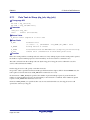
Activates Task (act_tsk, iact_tsk) ........................................................................... 60
Cancels Task Activation Request(can_act, ican_act) ............................................ 61
Activates Task with Start Code (sta_tsk, ista_tsk).................................................. 62
Terminates Current Task (ext_tsk)......................................................................... 63
Terminate Other Task (ter_tsk) .............................................................................. 64
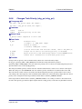
Changes Task Priority (chg_pri, ichg_pri) .............................................................. 65
Refers to Task Priority (get_pri, iget_pri)................................................................ 66
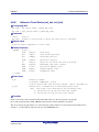
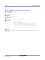
Refers to Task Status (ref_tsk, iref_tsk) ................................................................. 67
Refers to Task Status (Simplified Version) (ref_tst, iref_tst)................................... 69
Task Dependent Synchronization Function .......................................................71
5.7.1
5.7.2
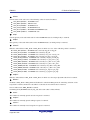
Puts Task to Sleep (slp_tsk, tslp_tsk) .................................................................... 72
Wakeup Task (wup_tsk, iwup_tsk)......................................................................... 73
REJ10J2052-0100
Page ii
Rev. 1.00 Aug. 28, 2009
RI600/4
Contents
5.7.3
5.7.4
5.7.5
5.7.6
5.7.7
5.8
Synchronization and Communication Function (Semaphore)............................79
5.8.1
5.8.2
5.8.3
5.9
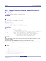
Cancels Task Wakeup Request (can_wup, ican_wup) .......................................... 74
Releases Task from WAITING State (rel_wai, irel_wai)......................................... 75
Suspends Task (sus_tsk, isus_tsk) ........................................................................ 76
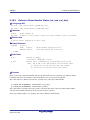
Resumes Suspended Task (rsm_tsk, irsm_tsk), Forcibly Resumes
Suspended Task (frsm_tsk, ifrsm_tsk) ................................................................... 77
Delays Task (dly_tsk)............................................................................................. 78
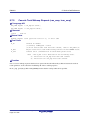
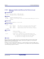
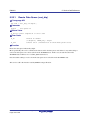
Releases Semaphore Resource (sig_sem, isig_sem)............................................ 80
Acquires Semaphore Resource (wai_sem, pol_sem, ipol_sem, twai_sem) ........... 81
Refers to Semaphore Status (ref_sem, iref_sem) .................................................. 82
Synchronization and Communication Function (Eventflag) ...............................83
5.9.1
5.9.2
5.9.3
5.9.4
Sets Eventflag (set_flg, iset_flg)............................................................................. 84
Clears Eventflag (clr_flg, iclr_flg)............................................................................ 85
Waits for Eventflag (wai_flg, pol_flg, ipol_flg, twai_flg)........................................... 86
Refers to Eventflag Status (ref_flg, iref_flg)............................................................ 88
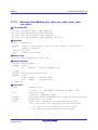
5.10 Synchronization and Communication Function (Data Queue)...........................89
5.10.1
5.10.2
5.10.3
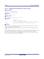
Sends to Data Queue (snd_dtq,psnd_dtq,ipsnd_dtq,tsnd_dtq, fsnd_dtq,
ifsnd_dtq) ............................................................................................................... 90
Receives from Data Queue (rcv_dtq, prcv_dtq, iprcv_dtq, trcv_dtq) ...................... 92
Refers to Data Queue Status (ref_dtq, iref_dtq)..................................................... 94
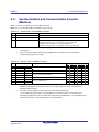
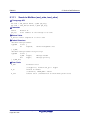
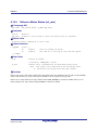
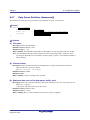
5.11 Synchronization and Communication Function (Mailbox)..................................95
5.11.1
5.11.2
5.11.3
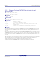
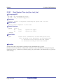
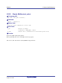
Sends to Mailbox (snd_mbx, isnd_mbx)................................................................. 96
Receices from Mailbox (rcv_mbx, prcv_mbx, iprcv_mbx, trcv_mbx)...................... 98
Refers to Mailbox Status (ref_mbx, iref_mbx) ...................................................... 100
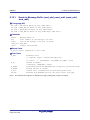
5.12 Extended Synchronization and Communication Function (Mutex) ..................101
5.12.1
5.12.2
5.12.3
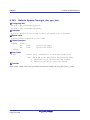
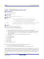
Locks Mutex (loc_mtx, ploc_mtx, tloc_mtx).......................................................... 102
Unlocks Mutex (unl_mtx)...................................................................................... 103
Refers to Mutex Status (ref_mtx) ......................................................................... 104
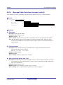
5.13 Extended Synchronization and Communication Function (Message
Buffer)...............................................................................................................105
5.13.1
5.13.2
5.13.3
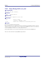
Sends to Message Buffer (snd_mbf, psnd_mbf, ipsnd_mbf, tsnd_mbf) ............... 106
Reveives from Message Buffer (rcv_mbf, prcv_mbf, trcv_mbf)............................ 108
Refers to Message Buffer Status (ref_mbf, iref_mbf) ........................................... 110
5.14 Memory Pool management Function (Fixed-sized Memory Pool) ...................111
5.14.1
5.14.2
5.14.3
Acquires fixed-sized memory block (get_mpf, pget_mpf, ipget_mpf,
tget_mpf) .............................................................................................................. 112
Releases Fixed-sized Memory Pool (rel_mpf, irel_mpf)....................................... 114
Refers to Fixed-sized Memory Pool (ref_mpf, iref_mpf)....................................... 115
5.15 Memory Pool management Function (Variable-sized Memory Pool) ..............116
5.15.1
5.15.2
5.15.3
Acquires variable-sized Memory Block (get_mpl, tget_mpl, pget_mpl,
ipget_mpl) ............................................................................................................ 117
Release Variable-sized Memory Block (rel_mpl).................................................. 119
Refers to Variable-sized Memory Pool Status (ref_mpl, iref_mpl)........................ 120
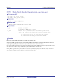
5.16 Time Management Function (System Time) ....................................................121
5.16.1
Sets System Time (set_tim, iset_tim)................................................................... 122
REJ10J2052-0100
Page iii
Rev. 1.00 Aug. 28, 2009
RI600/4
Contents
5.16.2
5.16.3
Refer to System Time (get_tim, iget_tim) ............................................................. 123
Supplies Time Tick (isig_tim) ............................................................................... 124
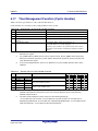
5.17 Time Management Function (Cyclic Handler)..................................................125
5.17.1
5.17.2
5.17.3
Starts Cyclic Handler Operation (sta_cyc, ista_cyc)............................................. 126
Stops Cyclic Handler Operation (stp_cyc, istp_cyc)............................................. 127
Refers to Cyclic Handler Status (ref_cyc, iref_cyc) .............................................. 128
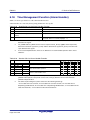
5.18 Time Management Function (Alarm Handler) ..................................................129
5.18.1
5.18.2
5.18.3
Starts Alarm Handler Operation (sta_alm, ista_alm) ............................................ 130
Stops Alarm Handler (stp_alm, istp_alm) ............................................................. 131
Refers to Alarm Handler Status (ref_alm, iref_alm).............................................. 132
5.19 System State Management Function ...............................................................133
5.19.1
5.19.2
5.19.3
5.19.4
5.19.5
5.19.6
5.19.7
5.19.8
5.19.9
5.19.10
5.19.11
5.19.12
Rotates Task Precedence (rot_rdq, irot_rdq) ....................................................... 134
Refers to Task ID in the RUNNING State (get_tid, iget_tid) ................................. 135
Locks the CPU (loc_cpu, iloc_cpu) ...................................................................... 136
Unlocks the CPU (unl_cpu, iunl_cpu)................................................................... 138
Disables Dispatching (dis_dsp) ............................................................................ 139
Enables Dispatching (ena_dsp) ........................................................................... 140
Refers to Context State (sns_ctx) ........................................................................ 141
Refers to CPU-Locked State (sns_loc)................................................................. 142
Refers to Dispatching-Disabled Dtate (sns_dsp).................................................. 143
Refers to Dispatching-Pending State (sns_dpn) .................................................. 144
Starts Kernel (vsta_knl, ivsta_knl) ........................................................................ 145
Terminates System (vsys_dwn, ivsys_dwn)......................................................... 146
5.20 Interrupt management Function .......................................................................147
5.20.1
5.20.2
5.20.3
Changes Interrupt Mask (chg_ims, ichg_ims) ...................................................... 148
Refers to Interrupt Mask (get_ims, iget_ims)........................................................ 150
Returns from kernel interrupt handler (ret_int) ..................................................... 151
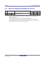
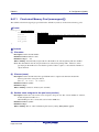
5.21 System Configuration Management Function ..................................................152
5.21.1
Refers to Version Information (ref_ver, iref_ver) .................................................. 153
5.22 Object Reset Function......................................................................................155
5.22.1
5.22.2
5.22.3
5.22.4
5.22.5
Resets Data Queue (vrst_dtq).............................................................................. 156
Resets Mailbox(vrst_mbx).................................................................................... 157
Resets Message Buffer (vrst_mbf)....................................................................... 158
Resets Fixed-sized Memory Pool (vrst_mpf)........................................................ 159
Resets Variable-sized Memory Pool (vrst_mpl) ................................................... 160
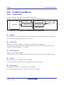
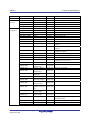
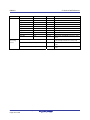
5.23 Constants and Macros .....................................................................................161
5.23.1
5.23.2
6.
Header Files......................................................................................................... 161
Content of Definition............................................................................................. 162
How to Write Application.............................................................. 165
6.1
6.2
6.3
Header Files .....................................................................................................165
Handling of Variables .......................................................................................165
Task..................................................................................................................166
6.3.1
6.3.2
Registration in the Kernel ..................................................................................... 166
Coding.................................................................................................................. 166
REJ10J2052-0100
Page iv
Rev. 1.00 Aug. 28, 2009
RI600/4
Contents
6.3.3
6.4
6.4.1
6.4.2
6.4.3
6.5
7.
Summary.............................................................................................................. 172
Coding.................................................................................................................. 172
CPU State at Start................................................................................................ 174
Precautions to Take when Using Floating-Point Arithmetic Instructions .........175
Precautions to Take when Using a Microcomputer that Supports the
DSP Function ...................................................................................................176
Procedure for Generating the Load Module ............................... 178
7.1
7.2
7.3
7.4
7.5
7.6
8.
Registration in the Kernel ..................................................................................... 170
Coding.................................................................................................................. 170
CPU State at Start................................................................................................ 171
System-Down Routine......................................................................................172
6.6.1
6.6.2
6.6.3
6.7
6.8
Registration in the Kernel ..................................................................................... 168
Coding.................................................................................................................. 168
CPU State at Start................................................................................................ 169
Time Event Handlers (Cyclic handlers and Alarm Handlers)...........................170
6.5.1
6.5.2
6.5.3
6.6
CPU State at Start................................................................................................ 167
Interrupt Handler ..............................................................................................168
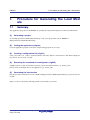
Summary ..........................................................................................................178
Creating Startup File (resetprg.c).....................................................................180
Kernel Libraries ................................................................................................185
Section List.......................................................................................................185
Service Call Information File (mrc file) and Essential Compiler Option ...........186
Processor Mode ...............................................................................................186
Configurator (cfg600) ................................................................... 187
8.1
8.2
8.3
8.4
Creating a Configuration File (cfg File) ............................................................187
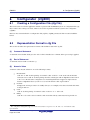
Representation Format in cfg File ....................................................................187
Default cfg File .................................................................................................189
Definition Items in cfg File ................................................................................190
8.4.1
8.4.2
8.4.3
8.4.4
8.4.5
8.4.6
8.4.7
8.4.8
8.4.9
8.4.10
8.4.11
8.4.12
8.4.13
8.4.14
8.4.15
System Definition (system)................................................................................... 191
Precautions to Take when Defining system.context............................................. 193
System Clock Definition (clock)............................................................................ 195
Task Definition(task[])........................................................................................... 197
Semaphore Definition (semaphore[]) ................................................................... 199
Eventflag Definition (flag[]) ................................................................................... 201
Datq Queue Definition (dataqueue[]).................................................................... 203
mailbox Definition (mailbox[]) ............................................................................... 205
Mutex Definition (mutex[]) .................................................................................... 207
Message Buffer Definition (message_buffer[]) ..................................................... 208
Fixed-sized Memory Pool (memorypool[])............................................................ 210
Variable-sized Memory Pool Definition (variable_memorypool[]) ......................... 212
Cyclic Handler Definition (cyclic_hand[]) .............................................................. 214
Alarm Handler Definition (alarm_hand[]) .............................................................. 216
Relocatable Vector Definition (interrupt_vector[])................................................. 217
REJ10J2052-0100
Page v
Rev. 1.00 Aug. 28, 2009
RI600/4
Contents
8.4.16
8.5
8.5.1
8.5.2
8.5.3
8.5.4
8.6
Outline of the Configurator ................................................................................... 221
Environment Settings ........................................................................................... 223
Configurator Start Procedure ............................................................................... 223
Command Options ............................................................................................... 223
Errors Messages ..............................................................................................224
8.6.1
8.6.2
9.
Fixed Vector Definition (interrupt_fvector[]) .......................................................... 219
Executing the Configurator...............................................................................221
Error Output Format and Error Levels.................................................................. 224
List of Messages .................................................................................................. 224
Table Generation Utility (mkritbl) ................................................ 227
9.1
9.2
9.3
9.4
Summary ..........................................................................................................227
Environment Setup...........................................................................................228
Table Generation Utility Start Procedure .........................................................228
Notes ................................................................................................................228
10. GUI Configurator........................................................................... 229
11. Sample Program ........................................................................... 230
11.1 Overview ..........................................................................................................230
11.2 Source Listing...................................................................................................231
11.3 Sample cfg File.................................................................................................232
12. Method for Calculating the Stack Size ........................................ 233
12.1
12.2
12.3
12.4
Types of Stacks................................................................................................233
"Call Walker" ....................................................................................................233
Calculating the User Stack Size of Each Task.................................................234
Calculating the System Stack Size ..................................................................235
REJ10J2052-0100
Page vi
Rev. 1.00 Aug. 28, 2009
RI600/4
1.
1. Composition of This Manual
Composition of This Manual
This manual is composed of the following chapters.
❏ 2. Overview
Presents an outline of this product.
❏3.Introduction to the Kernel
Describes the concept of this product to be understood before it is used and the basic matters regarding the
kernel that is the nucleus of this product.
❏4. Kernel Functions
Describes various functions of the kernel.
❏5.Service Call Reference
Shows service call specifications of the kernel.
❏6.How to Write Application
Explains how to write tasks and handlers.
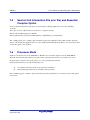
❏7. Procedure for Generating the Load Module
Outlines the procedure for generating load modules.
❏8. Configurator (cfg600)
Explains how to create the cfg file that is input to the command line configurator cfg600 and how to use the
cfg600.
❏9. Table Generation Utility (mkritbl)
Explains how to use the table generation utility mkritbl.
❏10. GUI Configurator
Presents general information about the GUI configurator. See online help for details on how to use the GUI
configurator.
REJ10J2052-0100
Page 1 of 235
Rev. 1.00 Aug. 28, 2009
RI600/4
1. Composition of This Manual
❏11. Sample Program
Explains about the sample application.
❏12. Method for Calculating the Stack Size
Explains how to calculate the stack sizes needed for tasks or handlers.
REJ10J2052-0100
Page 2 of 235
Rev. 1.00 Aug. 28, 2009
RI600/4
2. Overview
2.
Overview
2.1
Features
(1)
Compliant with µITRON 4.0 Specification
The RI600/4 was developed based on µITRON 4.0 specification, the latest version of µITRON specifications.
Therefore, the knowledge acquired from µITRON specification-related various publications or seminars, etc.
can be made use of directly. In addition, the application programs developed using other µITRON-compliant
real-time OS's can be ported to the RI600/4 relatively easily.
(2)
Increased processing speed
By taking advantage of the RX600-series microcomputer architecture, the processing speed is significantly
increased.
(3)
Systems always built to minimum size by automatically selecting only the
necessary modules
The RI600/4 kernel is supplied in RX600-series object library form. This means that from among numerous
functional modules of the kernel, only those that an application uses are automatically selected, thanks to the
functionality the linkage editor has. Therefore, systems are always generated in minimum size.
(4)
Efficient development possible by making use of the integrated development
environment
Renesas' integrated development environment, or High-performance Embedded Workshop, can be used as you
proceed with development work. High-performance Embedded Workshop supports the function to generate
workspaces for RI600/4-compatible applications. Furthermore, the real-time OS debug functions of
High-performance Embedded Workshop are also usable for the RI600/4.
(5)
Kernel building made easy by the configurator
The RI600/4 comes with the command line configurator cfg600. By only writing various kernel-building
information in a text-format cfg file, it is possible to build the kernel. This configurator information, as it is
created in text form, can be altered and maintained easily.
In addition, a GUI version of the configurator is available. The GUI configurator permits you to build the
kernel easily without the need to learn about the description format of the cfg file.
REJ10J2052-0100
Page 3 of 235
Rev. 1.00 Aug. 28, 2009
RI600/4
2.2
(1)
2. Overview
Supplied Software Composition
Kernel
This is the real-time OS body for RX600-series microcomputers.
(2)
cfg600 (command line configurator)
This is a tool to build the kernel. It accepts as its input the cfg file created by the user and outputs a kernel
definition file.
(3)
mkritbl (table generation utility)
This is the command line tool that by gathering the service call information used by an application, generates
the service call and interrupt vector tables most suitable for the application.
(4)
GUI configurator
This is a tool to build the kernel. From the kernel-building information supplied on the GUI screen, it outputs a
cfg file.
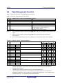
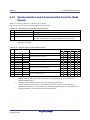
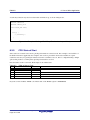
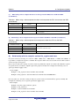
2.3
Operating Environment
The operating environment is shown in Table 2.1.
Table 2.1 Operating Environment
Item
Operating Environment
Target CPU core
RX CPU
Host machine
IBM-PC/AT compatible machine operated under Windows® 2000, Windows® XP, or
Windows Vista®
Compiler
Renesas C/C++ Compiler Package for RX Family
REJ10J2052-0100
Page 4 of 235
Rev. 1.00 Aug. 28, 2009
RI600/4
3. Introduction to the Kernel
3.
Introduction to the Kernel
3.1
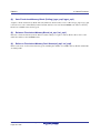
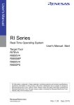
Operating Principle of the Kernel
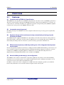
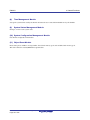
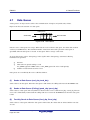
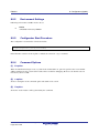
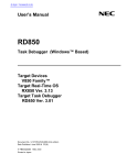
The kernel program is the nucleus of the realtime operating system. The kernel enables one CPU to appear as if
multiple CPUs are operating. How does the kernel do this? As is shown in Figure 3.1, the kernel switches
operation between various tasks as required.
Key input task
Remote controller
task
LED control
task
Sound volume
control task
Motor control
task
Machine control
task
Time
Figure 3.1
Operation of Multiple Tasks
This switching between tasks is called task dispatch. The kernel dispatches tasks in the following cases.
When a task itself requests a dispatch
When an event (such as an interrupt) outside the current task requests a dispatch
This means that tasks are not switched at predetermined intervals as in a time-sharing system. This type of
scheduling is generally called event-driven.
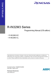
After a task is dispatched, execution of the task resumes from the point at which it was previously suspended
(Figure 3.2).
REJ10J2052-0100
Page 5 of 235
Rev. 1.00 Aug. 28, 2009
RI600/4
3. Introduction to the Kernel
Program is
resumed
Program is
suspended
Key input
task
Remote controller
task
……
During this interval, it
appears that the key input
microcomputer is halted.
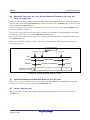
Figure 3.2
Suspending and Resuming a Task
In Figure 3.2, it appears to the programmer that the key input task or its microcomputer is halted while another
task assumes execution control.
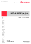
By restoring the contents of CPU registers that were stored when a task was suspended, the kernel resumes the
execution of a task from the state in which it was suspended. In other words, dispatching a task means saving
the contents of the CPU registers for the task currently being executed in a memory area prepared for the
management of that task, and restoring the contents of the CPU registers for the task for which execution is
being resumed (Figure 3.3)
Memory
R1
CPU registers
Saving
……
R2
Area for storage of
register data for the
key-input task
R1
PC
……
……
R2
PC
R1
R2
……
Restoration
Area for storage of
register data for the
remote-controller task
PC
Figure 3.3 Task Dispatch
As well as the CPU registers, task execution requires stack areas. Separate stack area must be allocated for each
task.
REJ10J2052-0100
Page 6 of 235
Rev. 1.00 Aug. 28, 2009
RI600/4
3.2
3. Introduction to the Kernel
Service Call
How does the programmer use the kernel functions in a program?
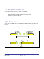
First, it is necessary to call up kernel function from the program in some way or other. Calling a kernel function
is referred to as a service call. Task activation and other processing operations can be initiated by such a service
call (Figure 3.4).
Key input
task
Task
scheduling
Service call
Kernel
Figure 3.4
Remote controller
task
Service Call
This service call is realized by a function call when the application program is written in C language, as shown
below
act_tsk(ID_TASK1);
3.3
Object
The processing objectives of service calls, such as tasks or semaphores, are called objects. Objects are
distinguished by their ID numbers.
However, if a task number is directly written in a program, the resultant program would be very low in
readability. If, for instance, the following is entered in a program, the programmer is constantly required to
know what the No. 1 task is.
act_tsk(1);
Further, if this program is viewed by another person, he/she does not understand at a glance what the No. 1 task
is.
To avoid such inconvenience, the RI600/4 provides means of specifying the task by name (ID name). The
program named "configurator cfg600 ,"which is supplied with the RI600/4, then automatically converts the
task name to the task ID number. To be more specific, the cfg600 outputs the header file "kernel_id.h" which
includes definitions of the following type, associating task ID names with task ID numbers.
#define ID_TASK1 1
Figure 3.5 is a schematic view of the task identification system.
REJ10J2052-0100
Page 7 of 235
Rev. 1.00 Aug. 28, 2009
RI600/4
3. Introduction to the Kernel
act_tsk(task name)
Name → ID number
Configurator
Start the task
having
the designated ID
number
Figure 3.5 Task Identification
With this task identification system, our earlier example is now as follows.
act_tsk(ID_TASK1); /* Start the task having the ID name "ID_TASK" */
This call specifies invocation of the task corresponding to "ID_TASK1". Also note that the compiler's
pre-processor converts task names to ID numbers in the generation of an executable program. Therefore, this
feature does not reduce processing speeds.
Although the example on this section just referred to task identification, other objects that have ID numbers can
also be given ID names.
REJ10J2052-0100
Page 8 of 235
Rev. 1.00 Aug. 28, 2009
RI600/4
3.4
3. Introduction to the Kernel
Task
3.4.1
Task State
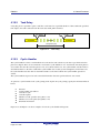
The kernel checks the task state to control whether to execute a task. For example, Figure 3.6 shows the state of
the key input task and its execution control. When a key input is detected, the kernel must execute the key input
task; that is, the key input task enters the RUNNING state. While waiting for a key input, the kernel does not
need to execute the key input task; that is, the key input task is in the WAITING state.
Key input
task
RUNNING state
WAITING state
RUNNING state
Figure 3.6 Task States
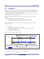
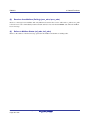
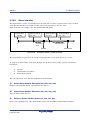
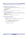
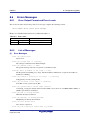
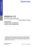
The kernel controls transitions between six states, including the RUNNING and WAITING states, as shown in
Figure 3.7. A task makes the transitions between these six states.
(1)
DORMANT state
The task has been registered in the kernel, but has not yet been initiated, or has already been terminated.
(2)
READY state
The task is ready for execution, but cannot be executed because another higher priority task is currently
running.
(3)
RUNNING state
The task is currently running. The kernel puts the READY task with the highest priority in the RUNNING
state.
(4)
WAITING state
When the task issues a service call such as tslp_tsk and the specified conditions are not satisfied, the task enters
the WAITING state. A task is released from the WAITING state by the service call (such as wup_tsk) that
corresponds to the call which initiated the WAITING state, after which the task enters the READY state.
(5)
SUSPENDED state
A task has been suspended by another task through sus_tsk.
(6)
WAITING-SUSPENDED state
This state is a combination of the WAITING state and SUSPENDED state.
REJ10J2052-0100
Page 9 of 235
Rev. 1.00 Aug. 28, 2009
RI600/4
3. Introduction to the Kernel
dispatch
READY
RUNNING
preempted
release from
waiting
wait
WAITING
resume
suspend
WAITING-SUSPENDED
release from
waiting
resume
suspend
SUSPENDED
suspend
forcibly
terminate
activate
DORMANT
forcibly terminate
Figure 3.7 Task State Transition Diagram
REJ10J2052-0100
Page 10 of 235
Rev. 1.00 Aug. 28, 2009
exit
RI600/4
3.4.2
3. Introduction to the Kernel
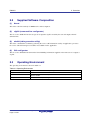
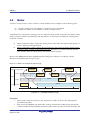
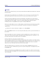
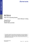
Task Scheduling (Priority and Ready Queue)
For each task, a task priority is assigned to determine the priority of processing. A smaller value indicates a
higher priority level and level 1 is the highest priority. The range of available priorities is 1 to system.priority
as defined in the cfg file.
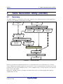
The kernel selects the highest-priority task from among the READY tasks and puts it in the RUNNING state.
The same priority can be assigned to multiple tasks. When there are multiple READY tasks with the highest
priority, the kernel selects the first task to have become READY and puts it in the RUNNING state. To
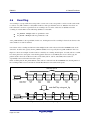
implement this behavior, the kernel has ready queues, which are queues of READY task waiting for execution.
Figure 3.8 shows the ready queue configuration. A ready queue is provided for each priority level, and the
kernel selects the task at the head of the non-empty ready queue for the highest priority and puts it in the
RUNNING state.
Task
priority
1
Task A
Task B
Task C
Task D
Task F
Task G
2
Task E
…………
3
n
Figure 3.8
REJ10J2052-0100
Page 11 of 235
Ready Queues (Waiting for Execution)
Rev. 1.00 Aug. 28, 2009
RI600/4
3.4.3
3. Introduction to the Kernel
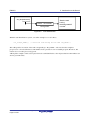
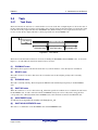
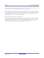
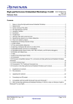
Task Waiting Queue
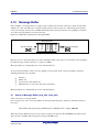
A service call can make a task wait (enter the WAITING state) until a condition designated in terms of objects
(such as semaphores and eventflags) has been satisfied. For some types of objects, two or more tasks may be in
the WAITING state. Attributes that select the order in which waiting tasks are handled are specifiable when the
objects are created. The specifiable attributes are TA_TFIFO (handling on an FIFO basis) or TA_TPRI
(handling on a priority basis).
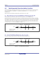
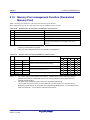
Tasks leave the WAITING state in the order specified for the waiting queue. Figure 3.9 and Figure 3.10 show
the order of task handling for objects with the respective attributes, where task D (priority: 9), task C (priority:
6), task A (priority: 1), and task B (priority: 5) have joined the waiting queue, in that order.
Object ID number
1
2
…………
3
Task A
Task B
Task C
Task D
Priority 1
Priority 5
Priority 6
Priority 9
n
Figure 3.9 Waiting Queue with the Attribute TA_TPRI
Object ID number
1
2
…………
3
Task D
Task C
Task A
Task B
Priority 9
Priority 6
Priority 1
Priority 5
n
Figure 3.10
REJ10J2052-0100
Page 12 of 235
Waiting Queue with the Attribute TA_TFIFO
Rev. 1.00 Aug. 28, 2009
RI600/4
3.5
3. Introduction to the Kernel
System State
The system state is classified into the following orthogonal states.
Task context / non-task context
Dispatching-disabled state / Dispatching-enabled state
CPU-locked state / CPU-unlocked state
The system operations and available service calls are determined based on the above system states.
3.5.1
Task Context and Non-Task Context
System is in either task contexts or non-task contexts. The difference between task contexts and non-task
contexts is described in Table 3.1.
Table 3.1
Task Context and Non-Task Context
Item
Task Context
Non-Task Context
Available service calls
Service calls that can be called
Service calls that can be called
from task context
from non-task context
Task scheduling
Refer to sections 3.5.2 and 3.5.3
Does not occur
The following forms of processing are executed in non-task contexts.
Interrupt handlers
Time event handlers (cyclic handlers and alarm handlers)
3.5.2
Dispatching-Disabled State / Dispatching-Enabled State
System is in either the dispatching-disabled state or the dispatching-enabled state. In the dispatching-disabled
state, task scheduling is not allowed and service calls that place the current task in the WAITING state cannot
be used.
The following service calls changes the system state to the dispatching-disabled state.
dis_dsp
chg_ims, that changes the interrupt mask to other than 0
The following service calls changes the system state to the dispatching-enabled state.
ena_dsp
chg_ims, that changes the interrupt mask to 0
Issuing the sns_dsp service call will check whether the system is in the dispatching-disabled state or not.
REJ10J2052-0100
Page 13 of 235
Rev. 1.00 Aug. 28, 2009
RI600/4
3. Introduction to the Kernel
It is possible to control it exclusively with tasks by using the dispatching-disabled state. However, because
other tasks cannot executes while the dispatching-disabled, it influences the behavior of the entire system. To
control between tasks exclusively, semaphore or mutex is recommended to be used as much as possible. It is
necessary to shorten the time of the dispatching-disabled state as much as possible.
3.5.3
CPU-Locked State / CPU-Unlocked State
System is in either the CPU-locked state or the CPU-unlocked state. In the CPU-locked state, interrupts and
task scheduling are not allowed. Note, however, that non-kernel interrupts are allowed.
Any service calls that make tasks enter the WAITING state cannot be issued. Issuing the loc_cpu or iloc_cpu
service call changes the system state to the CPU-locked state. Issuing an unl_cpu or iunl_cpu will return the
system state to the CPU-unlocked state. In addition, issuing the sns_loc service call will check whether the
system is in the CPU-locked state or not.
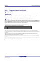
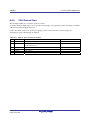
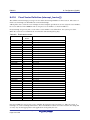
Service calls that can be issued in the CPU-locked state are restricted to those listed in Table 3.2.
Table 3.2
Service Calls that can be issued in the CPU-Locked State
loc_cpu, iloc_cpu
unl_cpu, iunl_cpu
sns_ctx
sns_loc
sns_dpn
vsta_knl, ivsta_knl
vsys_dwn, ivsys_dwn
ext_tsk *
sns_dsp
Note: This service call cancels the CPU-locked state.
It is possible to control it exclusively with kernel interrupt processings or tasks and kernel interrupt processings
by using the CPU-locked state. However, because other tasks cannot execute and kernel interrupts are masked
while the CPU-locked, it influences the behavior of the entire system. It is necessary to shorten the time of the
CPU-locked state as much as possible.
3.5.4
Dispatching-Pending State
The state that task-dispatching is pended is called the dispatching-pending state. To be more specific, each of
the following cases corresponds to the dispatch-pending state.
Non-task context
Dispatching-disabled state
CPU-locked state
The sns_dpn service call can be used to check if the system is in the dispatch-pending state.
REJ10J2052-0100
Page 14 of 235
Rev. 1.00 Aug. 28, 2009
RI600/4
3.6
3. Introduction to the Kernel
Processing Units and Precedence
An application program is executed in the following processing units.
(1)
(2)
(3)
Task
A task is a unit controlled by multitasking.
Interrupt handler
An interrupt handler is executed when an interrupt occurs.
Time Event Handler (Cyclic Handler and Alarm Handler):
A time event handler is executed when a specified cycle or time has been reached.
The various processing units are processed in the following order of precedence.
(1) Interrupt handlers, time event handlers
(2) Dispatcher (part of kernel processing)
(3) Task
The dispatcher is kernel processing that switches the task being executed. Since interrupt handlers and time
event handlers have higher precedence than the dispatcher, no tasks are executed while these handlers are
executing.
The precedence of an interrupt handler becomes higher when the interrupt level is higher.
The precedence of a time event handler is the same as the timer interrupt level (clock.IPL).
The order of precedence for tasks depends on the priority of the tasks.
REJ10J2052-0100
Page 15 of 235
Rev. 1.00 Aug. 28, 2009
RI600/4
3.7
3. Introduction to the Kernel
Interrupts
When an interrupt occurs, the interrupt handler defined in the cfg file is initiated.
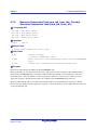
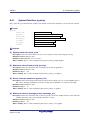
3.7.1
Type of Interrupt
Interrupt is classified into kernel interrupt and non-kernel interrupt.
Kernel Interrupt
An interrupt whose interrupt priority level is lower than or equal to the kernel interrupt mask level
(system.system_IPL) is called the kernel interrupt.
Service calls can be issued from within a kernel interrupt handler.
Note, however, that handling of kernel interrupts generated during kernel processing may be
delayed until the interrupts become acceptable.
Non-Kernel Interrupt
An interrupt whose interrupt priority level is higher than the kernel interrupt mask level
(system.system_IPL) is called the non-kernel interrupt. And, fixed vector interrupts are also
classified into non-kernel interrupt.
No service calls can be issued from within a non-kernel interrupt handler.
Non-kernel interrupts generated during service-call processing are immediately accepted whether
or not kernel processing is in progress
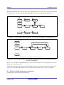
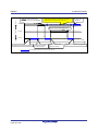
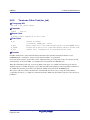
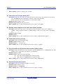
Figure 3.11 shows the relationship between the non-kernel interrupt handlers and kernel interrupt handlers
where the kernel mask level is set to 10.
Kenrel interrupt mask level
(system.system_IPL)
Low
1
High
2
3
4
5
6
7
8
Kernel interrupts
Figure 3.11
REJ10J2052-0100
Page 16 of 235
Rev. 1.00 Aug. 28, 2009
9
10 11 12 13 14 15
Non-kernel
interrupts
Interrupt handler IPLs
RI600/4
3. Introduction to the Kernel
I bit and IPL bit of the PSW Register
3.7.2
In the CPU specification, all interrupts are masked when I bit is 0, and interrupts at the level below the IPL bit
value is masked when I bit is 1.
Please refer to the next paragraph for the change in I bit and the IPL bit by the application.
(1)
Task
An initial value of the I bit is 1, and an initial value of the IPL bit is 0. In a word, all the interruptions are
permitted.
An task must not change the I bit to 0. Note, The RI600/4 does not provide a method to change the I bit.
In the change of IPL, there is a method of using loc_cpu or chg_ims.
(2)
Interrupt Handler
An initial value of the I bit is 1 when the handler is defined to be enable multiplex interrupts
(pragma_switch=E). When it is not so, an initial value of the I bit is 0.
An initial value of the IPL bit is the interrupt priority level. In the change of IPL, there is a method of using
iloc_cpu or ichg_ims.
And the I bit and IPL bit can be changed by an interrupt handler.
(3)
Time Event Handler
An initial value of the I bit is 1
An initial value of the IPL bit is the interrupt priority level of the timer interrupt.(clock.IPL in the .cfg file.). In
the change of IPL, there is a method of using iloc_cpu or ichg_ims.
And the I bit and IPL bit can be changed by an time event handler.
(4)
Contorl in a service call
(a)
(b)
(c)
I bit
When a service call is called from the task context, the service call runs while switching the I bit to 0
and 1.
When a service call is called from the non-task context, the I bit is maintained in the service call.
IPL bit
A service call runs while switching the IPL bit to the value before calling and the kernel interrupt
mask level (system.system_IPL).
State after a service call ends
The PSW register return to the value before calling. However, the IPL bit is changed by chg_ims,
ichg_ims, loc_cpu, iloc_cpu, unl_cpu, or iunl_cpu.
REJ10J2052-0100
Page 17 of 235
Rev. 1.00 Aug. 28, 2009
RI600/4
3.7.3
3. Introduction to the Kernel
Disabling Interrupts
To disable interrupts, follow one of the methods described below.
(1)
Disable unspecified interrupts (Change I bit and IPL bit of the PSW register)
(a)
(b)
(c)
(2)
Putting into the CPU-locked state
In the CPU-locked state, PSW.IPL is set to the kernel interrupt mask level (system.system_IPL).
Therefore, it is only the kernel interrupts that are disabled in the CPU-locked state. To disable
non-kernel interrupts, follow the method (b) or (c).
Also, when in the CPU-locked state, the usable service calls are subject to some limitations. See
Section 3.5.3, "CPU-Locked State / CPU-Unlocked State."
Use chg_ims or ichg_ims to alter PSW.IPL.
In non-task context, do not lower the IPL bit more than the value when the handler is started.
In task-context, the system enters to dispatching-disabled state when the IPL bit is changed to other
than 0, and the system enters to dispatching-enabled state when the IPL bit is changed to 0.
Usually, do not call ena_dsp while having changed the IPL bit to other than 0 If calling ena_dsp, the
system enters to dispatching-enabled state. The PSW register is changed to the value for dispatched
task, so the IPL may be lowered.
Handlers (non-task context) can change the I bit and IPL bit directly. However, do not lower the IPL
bit more than the value when the handler is started.
Note, the compiler provides following intrinsic functions for handling PSW register.
set_ipl() : Changes the IPL bit of the PSW register
get_ipl() : Refers to the IPL bit of the PSW register
set_psw() : Changes the PSW register
get_psw() : Refers to the PSW register
Disable specified interrupts
Change Interrupt Request Registers in the interrupt controller (ICU) or control registers of the I/O to disable
specified interrupts.
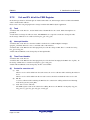
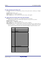
3.7.4
Usable Service Calls
(1) Since the interrupt hander is classified as belonging to non-task contexts, the task context-only
service calls cannot be used in the interrupt handler.
(2) When the PSW.IPL is larger than or equal to the kernel interrupt mask level (system.system_IPL),
1
such as non-kernel interrupt handlers, do not call service calls , If calling, the service call returns error
E_CTX. In this case, the PSW.IPL temporarily falls on the kernel interrupt mask level. Please use this
error only for the purpose of debugging.
1
Except chg_ims, ichg_ims, get_ims, iget_ims, vsta_knl, ivsta_knl, vsys_dwn, and ivsys_dwn
REJ10J2052-0100
Page 18 of 235
Rev. 1.00 Aug. 28, 2009
RI600/4
3.7.5
3. Introduction to the Kernel
Regarding Non-maskable Interrupt and Exceptions
The non-maskable interrupt are handled as non-kernel interrupt.
Furthermore, the following exceptions that are caused by instruction execution are handled as non-kernel
interrupt. Note,the E_CTX error is not detected when service call is issued from these interrupt handlers.
Undefined instruction exception
Privileged instruction exception
Access exception
Floating-point exception
INT instruction exception
BRK instruction exception
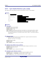
3.7.6
Fast Interrupt Function of the RX Microcomputer
The RX microcomputer supports the "fast interrupt" function. Only one interrupt source can be made the fast
interrupt. The fast interrupt is handled as the one that has interrupt priority level 15. To use the fast interrupt
function, make sure there is only one interrupt source that is assigned interrupt priority level 15.
For the fast interrupt function to be used in this kernel, it is necessary that the interrupt concerned be handled as
an non-kernel interrupt. In other words, the kernel interrupt mask level (system.system_IPL) must be set to 14
or below.
And "os_int = NO;" and "pragma_switch = F;" are required for interrupt_vector[] definition.
And the FINTV register must be initialized to the start address of the handler by application.
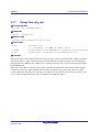
3.8
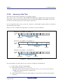
Stacks
Stack is classified into user stack and system stack.
User Stack
One user stack is provided for each task. User stack for each task is generated by specifying the
size and section name in the cfg file.
System Stack
The system stack is used by non-task context and the kernel. There is one system stack in the
system.
The system stack is generated by specifying system.stack_size in the cfg file.
REJ10J2052-0100
Page 19 of 235
Rev. 1.00 Aug. 28, 2009
RI600/4
4.
4. Kernel Functions
Kernel Functions
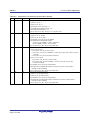
This section mainly describes the functions and usage of kernel service calls
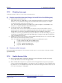
4.1
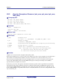
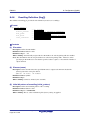
Module Structure
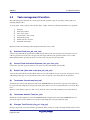
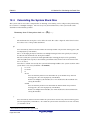
The kernel consists of the modules shown in Figure 4.1. Each of these modules is composed of functions that
exercise individual module features.
The kernel is supplied in the form of a library, and only necessary features are linked at the time of system
generation. More specifically, only the functions used are chosen from those which comprise these modules
and linked by means of the Linkage Editor. However, the scheduler module, part of the task management
module, and part of the time management module are linked at all times because they are essential feature
functions.
The applications program is a program created by the user. It consists of tasks, interrupt handler, alarm handler,
and cyclic handler.
User
module
Application program
Task management
Task-dependent
synchronization
Semaphore
Eventflag
Data queue
Mailbox
Mutex
Message buffer
Fixed-sized memory pool
Variable-sized
memory pool
Time management
Cyclic handler
Alarm handler
Interrupt management
System state
management
Kernel
System configuration management
Object reset
Scheduler
RX600 series MCU
Figure 4.1
REJ10J2052-0100
Page 20 of 235
Rev. 1.00 Aug. 28, 2009
Kernel Structure
Hardware
RI600/4
4.2
(1)
4. Kernel Functions
Module Overview
Scheduler
Forms a task processing queue based on task priority and controls operation so that the high-priority task at the
beginning in that queue (task with small priority value) is executed.
(2)
Task Management Module
Exercises task operation such as activation, termination, or changing task priority
(3)
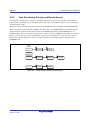
Task-Dependent Synchronization Module
Accomplishes inter-task synchronization by changing the task status from a different task.
(4)
Synchronization and Communication Module
This is the function for synchronization and communication among the tasks by using the objects independent
of task. The following five functional modules are offered.
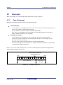
Semaphore
The semaphore is the object to prevent resources between tasks from competing.
Eventflag
The eventflag is the object that controls the execution control of tasks according to the condition of
AND/OR condition of the bit pattern.
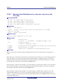
Data Queue
The data queue is the object to communicate the 1-word (32 bits) data.
Mailbox
The mailbox is the object to communicate messages with arbitrary size. The message is not copied,
the message address is transferred.
Mutex
The mutex is the object to prevent resources between tasks from competing. The mutex has the
function to evade the priority inversion problem.
Message Buffer
The message buffer is the object to communicate messages with arbitrary size. The message is
copied,
(5)
Fixed-sized Memory Pool
The fixed-sized memory pool is the object to allocate the fixed-sized memory block dynamically.
(6)
Variable-sized Memory Pool
The variable-sized memory pool is the object to allocate the memory block with arbitrary size dynamically.
(7)
Interrupt management Module
Makes a return from the interrupt handler.
REJ10J2052-0100
Page 21 of 235
Rev. 1.00 Aug. 28, 2009
RI600/4
(8)
4. Kernel Functions
Time Management Module
Sets up the system timer used by the kernel and starts the user-created alarm handler and cyclic handler.
(9)
System Status Management Module
Changes or refers to the system state.
(10) System Configuration Management Module
Gets kernel configuration information.
(11) Object Reset Module
Resets data queue, mailbox, message buffer, fixed-sized memory pool, and variable-sized memory pool.
This is the function outside µITRON 4.0 specification.
REJ10J2052-0100
Page 22 of 235
Rev. 1.00 Aug. 28, 2009
RI600/4
4.3
4. Kernel Functions
Task management Function
The task management functions are used to perform task operations such as activating, ending tasks, and
changing task priorities.
To create tasks, writes "task[]" in the cfg file. In the "task[]" statement, following information are specified.
ID name
Task entry address
Size of user stack
Section name of user stack
Task initial priority
Initial state after creation
Extended information
The kernel offers the following task management function service calls.
(1)
Activates Task (act_tsk, iact_tsk)
Activates the task with the specified ID. Unlike sta_tsk and ista_tsk, the activation requests by these service
calls are queued, but a start code to be passed to the target task cannot be specified in these service calls.
Extended information specified at the time of task creation is passed to the target task.
(2)
Cancels Task Activation Requests (can_act, ican_act)
Cancels the activation requests that have been queued for the task with the specified ID.
(3)
Starts Task (with start code) (sta_tsk, ista_tsk)
Activates the task with the specified ID. In either service call, unlike in act_tsk or iact_tsk, requests for service
call startup of this type are not queued, but a start code to be passed to the target task can be specified.
(4)
Terminates Current task (ext_tsk)
Terminates the current task, placing the task in the DORMANT state. If activation requests for the task have
been queued, task startup processing is performed again. In this case, the current task behaves as if it has been
reset.
Behavior of the task in response to this service call is the same as the task returning from its entry function.
(5)
Terminates Another Task (ter_tsk)
Terminates another task that is not in the DORMANT state and places the task in the DORMANT state. If
activation requests for the task have been queued, task startup processing is performed again.
(6)
Changes Task Priority (chg_pri, ichg_pri)
Changes the priority of the task with the specified ID. If the priority of a task is changed while the task is in the
REJ10J2052-0100
Page 23 of 235
Rev. 1.00 Aug. 28, 2009
RI600/4
4. Kernel Functions
READY or RUNNING state, the ready queue is also updated (Figure 4.2). Moreover, if the target task is placed
in the wait queue of an object with the TA_TPRI attribute, the wait queue is also updated (Figure 4.3).
Task
priority
1
Task A
Task B
Task C
Task B
Task E
Task F
2
Task D
…………
3
n
When the priority of task B has been changed from 3 to 1
Figure 4.2
Ready Queue When Changing a Task Priority in the READY or RUNNING State
Object ID number
1
2
…………
3
Task A
Task B
Task C
Task B
Priority 1
Priority 2
Priority 3
Priority 4
n
When the priority of task B has been changed from 2 to 4
Figure 4.3
Re-Arranging the Wait Queue When Changing Priority of a task waiting for the object
with TA_TPRI Attribute
However, it is generally recommended that these service calls not be used because changing the priority affects
the behavior of the entire system.
A task has two priority levels: base priority and current priority. In general operation, these two priority levels
are the same; they differ only while the task has a mutex locked. For details, refer to section 4.9, "Mutex."
(7)
Refers to Task Priority (get_pri, iget_pri)
Gets the priority of the task with the specified ID.
REJ10J2052-0100
Page 24 of 235
Rev. 1.00 Aug. 28, 2009
RI600/4
(8)
4. Kernel Functions
Refers to Task Status (ref_tsk, iref_tsk)
Refers to status of the task with the specified ID.
(9)
Refers to Task Status (Simplified Version) (ref_tst, iref_tst)
Refers to status of the task with the specified ID. Either service call produces less overhead than ref_tsk or
iref_tsk because it refers to less information.
REJ10J2052-0100
Page 25 of 235
Rev. 1.00 Aug. 28, 2009
RI600/4
4.4
4. Kernel Functions
Task-Dependent Synchronization Function
The task-dependent synchronization functions are used to achieve synchronization between tasks by placing
tasks in the WAITING, SUSPENDED, or WAITING-SUSPENDED states, or to wake up tasks in the
WAITING state.
The kernel offers the following task-dependent synchronization service calls.
(1)
Sleep Task (slp_tsk, tslp_tsk) and Wakes up Task (wup_tsk, iwup_tsk)
The slp_tsk puts the current task to sleep. The task in sleep becomes to the WAITING state.
The tslp_tsk performs the same function as slp_tsk except that a timeout period before wakeup is specifiable.
The wup_tsk or iwup_tsk wakes up a task from sleep state. The waked-up task is released from the WAITING
state. While the target task is not in sleep state, the issued wakeup requests are queued. If the task for which
wakeup requests have been queued calls slp_tsk or tslp_tsk, the wakeup request count is decremented by one
(-1) and the task does not enter the WAITING state (Figure 4.4).
wup_tsk
wup_tsk wup_tsk
slp_tsk
slp_tsk
Task
Number of wakeup
queuing count
0
Figure 4.4
(2)
0
1
2
1
Queuing Wakeup Request
Cancels Task Wakeup Request (can_wup, ican_wup)
Cancels the wakeup requests queued for a task with the specified ID (Figure 4.5).
wup_tsk
wup_tsk can_wup
slp_tsk
slp_tsk
Task
Number of wakeup
queuing count
0
Figure 4.5
REJ10J2052-0100
Page 26 of 235
Rev. 1.00 Aug. 28, 2009
0
1
0
Canceling Wakeup Requests
0
RI600/4
(3)
4. Kernel Functions
Suspends Task (sus_tsk, isus_tsk) and Resumes Task(rsm_tsk, irsm_tsk,
frsm_tsk, ifrsm_tsk)
Issuing sus_tsk or isus_tsk forcibly suspends the task with the specified ID. If the target task is in the READY
state, the task is placed in the SUSPENDED state. If the target task is in the WAITING state, the task is placed
in the WAITING-SUSPENDED state.
Only one suspension request can be nested, if sus_tsk or isus_tsk is issued to a task in the SUSPENDED state,
the error E_QOVR is returned.
The rsm_tsk or irsm_tsk decrements the suspension counts for a task with the specified ID. When the number
reaches 0, the task is taken out of the SUSPENDED state (Figure 4.6).
The frsm_tsk or ifrsm_tsk clears the suspension count for a task with specified ID, and the task is taken out of
the SUSPENDED state.
Because the maximum suspension count is 1, the behavior of the frsm_tsk and ifrsm_tsk is the same as the
rsm_tsk and irsm_tsk.
Error E_QOVR
sus_tsk
sus_tsk
rsm_tsk
Task
READY
SUSPENDED
WAITING
Number of nested
suspension count
WAITING-SUSPENDED
0
Figure 4.6
(4)
1
READY
WAITING
0
Suspending and Resuming Tasks
Forcible Releases from WAITING State (rel_wai, irel_wai)
The rel_wai or irel_wai forcibly releases the task with the specified ID from the WAITING state. Note that
neither service call can release a task from the SUSPENDED state.
(5)
Delays Task (dly_tsk)
The dly_tsk delays execution of the current task during the specified time. The current task enters to the
WAITING state.
REJ10J2052-0100
Page 27 of 235
Rev. 1.00 Aug. 28, 2009
RI600/4
4.5
4. Kernel Functions
Semaphore
A semaphore is an object used to prevent conflicts over resources such as devices or variables shared by
multiple tasks. For example, if task switching occurs while task A is updating a shared variable and task B
refers to this variable when updating of its value is not complete, task B may incorrectly read the shared
variable. Such conflicts can be prevented by using semaphores.
A semaphore provides exclusive control and a synchronization function by expressing the existence of a
resource or the number of resources as a counter.
Applications must be programmed so that semaphores are associated with resources to be exclusively
controlled.
Note the following rules on exclusive control using a semaphore.
(1) A task should acquire the semaphore before using the associated resource
(2) A task should release the semaphore after its usage of the resource is finished
To create semaphores, writes "semaphore[]" in the cfg file. In the "semaphore []" statement, following
information are specified.
ID name
How tasks are queued waiting for the semaphore
TA_TFIFO (queued in FIFO order) or TA_TPRI (queued in order of task priority)
Initial value of semaphore counter
Maximum value of semaphore counter
Figure 4.7 shows an example of semaphore usage.
wai_sem : Task A attempts to acquire
the semaphore but fails to enter the
WAITING state
Acquires the semaphore
Task A
Task B
Time
wai_sem : Acquires the semaphore
The current task is switched to
task A for some reason
sig_sem : Releases the semaphore
: Period over which the task has the semaphore (access to the associated resource is allowed)
Figure 4.7
Example of Semaphore Usage
Control related to semaphores is implemented by the service calls listed below.
REJ10J2052-0100
Page 28 of 235
Rev. 1.00 Aug. 28, 2009
RI600/4
(1)
4. Kernel Functions
Acquires Semaphore Resource (wai_sem, twai_sem)
Acquires a semaphore. If the semaphore's counter has a positive value, the counter is decremented by one. If
the semaphore cannot be acquired (semaphore count = 0), the task enters the WAITING state.
(2)
Acquires Semaphore Resource (Polling) (pol_sem, ipol_sem)
Acquires a semaphore. The only difference between these service calls and wai_sem or twai_sem is that an
error is immediately returned and the task does not enter the WAITING state when the semaphore count is 0.
(3)
Releases Semaphore Resource (sig_sem, isig_sem)
Releases a semaphore. When a task is waiting to acquire a semaphore, either service call makes the task leave
the WAITING state. If not, the counter is incremented by one.
(4)
Refers to Semaphore Status (ref_sem, iref_sem)
Refers to the state of a semaphore, including its counter and the IDs of waiting tasks.
4.5.1
Priority Inversion Problem
When a semaphore is used for exclusive control of a resource, a problem called priority inversion may arise.
This refers to the situation where a task that is not using a resource delays the execution of a task requesting the
resource.
Figure 4.8 illustrates this problem. In this figure, tasks A and C are using the same resource, which task B does
not use. Task A attempts to acquire a semaphore so that it can use the resource but enters the WAITING state
because task C is already using the resource. Task B has a priority higher than task C and lower than task A.
Thus, if task B is executed before task C has released the semaphore, release of the semaphore is delayed by
the execution of task B. This also delays acquisition of the semaphore by task A. From the viewpoint of task A,
a lower-priority task that is not even competing for the resource gets priority over task A.
To avoid this problem, use a mutex instead of a semaphore.
REJ10J2052-0100
Page 29 of 235
Rev. 1.00 Aug. 28, 2009
High
RI600/4
4. Kernel Functions
w ai_sem : Failed to acquire the
semaphore and enters the WAITING
state
Time taken for task A to acquire the semaphore
depends on the execution time of task B
Acquires the
semaphore
Task A
Priority
slp_tsk : Enters the WAITING state
Task B
Low
Task C
Time
wai_sem : Acquires the semaphore
Task A is executed
for some reason
Task B is executed
for some reason
: The semaphore has been acquired in this period.
Figure 4.8
REJ10J2052-0100
Page 30 of 235
Rev. 1.00 Aug. 28, 2009
Priority Inversion Problem
sig_sem : Releases the semaphore
RI600/4
4.6
4. Kernel Functions
Eventflag
An eventflag is a group of bits that correspond to events. One event corresponds to one bit. A task can be made
to wait for one (OR condition) or all (AND condition) of the specified bits to be set. Whether more than one
task is allowed to wait for a specific bit of an eventflag to be set can be selected as an attribute when the
eventflag is created. Either of the following attributes is selectable.
TA_WMUL : Multiple tasks are permitted to wait
TA_WSGL : Multiple tasks not permitted to wait
A TA_CLR attribute is also specifiable; in this case, the bit pattern of the eventflag is cleared to 0 whenever the
wait condition of a task is satisfied.
One feature of the eventflag mechanism is that multiple tasks can be released from the WAITING state at the
same time. To allow this, specify the TA_WMUL attribute. Do not specify the TA_CLR attribute in this case.
Figure 4.9 shows an example of task execution control by an eventflag. In this figure, six tasks, task A to task F,
have been placed in a wait queue. After the flag pattern has been set to 0x0F by the service call set_flg, the
pattern satisfies the wait conditions for three of the tasks (task A, task C, and task E). These tasks are
sequentially removed from the head of the queue.
If this eventflag has the TA_CLR attribute, when task A is released from the WAITING state, the bit pattern of
the eventflag will be set to 0, and task C and task E will not be removed from the queue.
Task wait queue
Evemtf lag
Task A
Task B
Task C
Task D
Task E
Task F
0x0F
OR
0xFF
AND
0x0F
AND
0xFF
AND
0xFF
OR
0x30
OR
Flag pattern= 0
Wait pattern
Wait mode
sets 0x0F by using set_flg
Evemtf lag
Task B
Task D
Flag pattern = 0x0F
Figure 4.9
REJ10J2052-0100
Page 31 of 235
Rev. 1.00 Aug. 28, 2009
Example of Eventflag Usage
Task F
RI600/4
4. Kernel Functions
To create eventflags, writes "flag[]" in the cfg file. In the "flag []" statement, following information are
specified.
ID name
How tasks are queued waiting for the semaphore
TA_TFIFO (queued in FIFO order) or TA_TPRI (queued in order of task priority)
Initial pattern of eventflag
Multiple wait permission attribute
TA_WMUL (multiple tasks are permitted to wait) or TA_WSGL (multiple tasks not permitted to
wait)
Clear attribute (TA_CLR)
Control related to eventflags is implemented by the service calls listed below.
(1)
Waits for Eventflag (wai_flg, twai_flg)
Makes a task wait until specific bits in the eventflag have been set. Select either of the following wait
conditions.
AND condition : Waits until all of the specified bits have been set
OR condition : Waits until any of the specified bit have been set
When a task is released from the WAITING state, the value of the eventflag at satisfaction of the wait
condition is returned to the task that issued this service call. If the TA_CLR attribute has been specified for the
eventflag, the eventflag is also cleared to 0. In this case, the value of the eventflag immediately before it was
cleared is returned to the task that issued this service call.
(2)
Acquires Eventflag (Polling) (pol_flg, ipol_flg)
Checks if specified bits in an eventflag have been set. The only difference between these service calls and
wai_flg or twai_flg is that an error code is immediately returned and the task does not enter the WAITING
state when the condition is not satisfied.
(3)
Sets Eventflag (set_flg, iset_flg)
Sets an eventflag to a specified bit pattern. This may release tasks with wait conditions that match the pattern.
(4)
Clears Eventflag (clr_flg, iclr_flg)
Clears specified bits of an eventflag.
(5)
Refers to Eventflag Status (ref_flg, iref_flg)
Refers to the state of an eventflag, including its bit pattern and the IDs of waiting tasks.
REJ10J2052-0100
Page 32 of 235
Rev. 1.00 Aug. 28, 2009
RI600/4
4.7
4. Kernel Functions
Data Queue
A data queue is an object used to achieve the communication of single word (32-bit units) of data.
Figure 4.10 shows the structure of a data queue.
Figure 4.10
data
data
Sends data
data
data
Data queue
Receives data
Data Queue
Data are sent to a data queue for storage. When data are received from a data queue, the oldest data are taken
out first (on an FIFO basis). The maximum number of data items that can be queued in a data queue is
specifiable when the data queue is created. A data queue with no storage can be used.
To create data queues, writes "dataqueue[]" in the cfg file. In the "dataqueue[]" statement, following
information are specified.
ID name
How tasks are queued waiting to send
TA_TFIFO (queued in FIFO order) or TA_TPRI (queued in order of task priority)
Number of data items that can be stored
Data queues are controlled by the service calls listed below.
(1)
Sends to Data Queue (snd_dtq, tsnd_dtq)
Sends a data to an data queue. When the data queue is full of data, the calling task enters the WAITING state.
(2)
Sends to Data Queue (Polling) (psnd_dtq, ipsnd_dtq)
Sends a data to a data queue. The only difference between these service calls and snd_dtq or tsnd_dtq is that an
error code is immediately returned and the calling task does not enter the WAITING state when the data queue
is full.
(3)
Forcibly Sends to Data Queue (fsnd_dtq, ifsnd_dtq)
Sends a data to a data queue. When the data queue is full of data, the oldest data are deleted and the new data
are sent.
REJ10J2052-0100
Page 33 of 235
Rev. 1.00 Aug. 28, 2009
RI600/4
(4)
4. Kernel Functions
Receives from Data Queue (rcv_dtq, trcv_dtq)
Receives a data from a data queue. When the data queue has no data, the calling task enters the WAITING state.
If the data queue was full of data and a task was waiting to send data, this call releases the first task in the wait
queue for sending data from the WAITING state.
(5)
Receives from Data Queue (Polling) (prcv_dtq, iprcv_dtq)
Receives a data from a data queue. When the data queue has no data, an error code is returned. If the data
queue was full of data and a task was waiting to send data, this call releases the first task in the wait queue for
sending data from the WAITING state.
(6)
Refers to Data Queue Status (ref_dtq, iref_dtq)
Refers to the state of a data queue, including the number of data stored in the queue, the ID of task waiting to
send, and the ID of task to receive data.
REJ10J2052-0100
Page 34 of 235
Rev. 1.00 Aug. 28, 2009
RI600/4
4.8
4. Kernel Functions
Mailbox
A mailbox is an object used to send or receive messages, which are data with arbitrary size.
Figure 4.11 shows the structure of a mailbox.
Mailbox
Message queue
Sends message
Receives message
Figure 4.11
Mailbox
High-speed data communications are achieved regardless of the message size because only the addresses where
the messages start are sent and received. Applications should create messages in memory areas that are
accessible by both the sending and receiving tasks (i.e., messages should not be created in the local variable
areas). A sending task should not access the message area after it has sent the message.
Messages transmitted to mailbox are managed by message queue. The messages are received in order of
message queue.
Either the following can be selected as the order of message queue.
TA_MPRI attriburte : Queued in order of message's priority
TA_MFIFO attribute : Queued in FIFO order
To create mailboxes, writes "mailbox[]" in the cfg file. In the "mailbox[]" statement, following information are
specified.
ID name
How tasks are queued waiting to receive
TA_TFIFO (queued in FIFO order) or TA_TPRI (queued in order of task priority)
How messages are queued
TA_MFIFO (queued in FIFO order) or TA_MPRI (queued in order of message's priority)
Maximum message priority
Mailboxes are controlled by the service calls listed below.
(1)
Sends to Mailbox (snd_mbx, isnd_mbx)
Sends a message to a mailbox.
(2)
Receives from Mailbox (rcv_mbx, trcv_mbx)
Receives a message from a mailbox. When the mailbox has no message, the task is in the WAITING state until
a message is sent to the mailbox.
REJ10J2052-0100
Page 35 of 235
Rev. 1.00 Aug. 28, 2009
RI600/4
(3)
4. Kernel Functions
Receives from Mailbox (Polling) (prcv_mbx, iprcv_mbx)
Receives a message from a mailbox. The only difference between these service calls and rcv_mbx or trcv_mbx
is that an error code is immediately returned and the task does not enter the WAITING state when the mailbox
has no message.
(4)
Refers to Mailbox Status (ref_mbx, iref_mbx)
Refers to the address of the first message queued in the mailbox and the IDs of waiting tasks.
REJ10J2052-0100
Page 36 of 235
Rev. 1.00 Aug. 28, 2009
RI600/4
4. Kernel Functions
4.9
Mutex
A mutex is an object used to achieve exclusive control. It differs from a semaphore on the following points.
(1)
(2)
A priority ceiling protocol is applied to avoid priority inversion problems.
A mutex can only be used for exclusive control of a single resource.
Original behavior of the priority ceiling protocol is to make the current priority of the task to the highest ceiling
priority of mutexes which are locked by the task. This behavior is achieved by controlling the current priority
of the task as follows.
When a task locks a mutex, changes the current priority of the task to the highest ceiling priority of
mutexes which are locked by the task.
When a task unlocks a mutex, changes the current priority of the task to the highest ceiling priority
of mutexes which continues to be locked by the task. When there is no mutex locked by the task
after unlock, returns the current priority of the task to the base priority.
However, the RI600/4 kernel adopts simplified priority ceiling protocol because of reducing overhead.
Therefore, the underlined part is not processed.
WAITING
READY
RUNNING
Priority
Task C
RUNNING
1
READY
unl_mtx
RUNNING
RUNNING
loc_mtx
WAITING
Task B
Lower
RUNNING
WAITING
RUNNING
loc_mtx
Task A
RUNNING
unl_mtx
Ceiling priority
loc_mtx
Higher
unl_mtx
Figure 4.12 shows an example of mutex usage.
RUNNING
READY
2
3
Figure 4.12
4
5
6
Time
Example of Mutex Usage
Description:
1
2
Task C locks a mutex by issuing loc_mtx. The priority of task C is raised to the ceiling priority
specified for the mutex.
Task A enters the READY state while task C is being executed at the ceiling priority. The priority
of task A is higher than that initially specified for task C. However, task C now locks the mutex and
REJ10J2052-0100
Page 37 of 235
Rev. 1.00 Aug. 28, 2009
RI600/4
3
4
5
6
7
4. Kernel Functions
is thus executed at the ceiling priority. Since this is higher than that of task A, task A cannot enter
the RUNNING state. In other words, while task C has the mutex locked, execution of task C
continues even if task A, with its higher initial priority, becomes ready.
Task C unlocks the mutex by issuing unl_mtx. The priority of task C returns to the initial level and
higher-priority task A enters the RUNNING state.
Task A issues loc_mtx to raise its priority to the ceiling priority.
Task A issues unl_mtx to return its priority to the initial level.
Task B issues loc_mtx to raise its priority to the ceiling priority.
Task B issues unl_mtx to return its priority to the initial level.
To create mutexes, writes "mutex[]" in the cfg file. In the "mutex[]" statement, following information are
specified.
ID name
Ceiling priority
Mutexes are controlled by the service calls listed below.
(1)
Locks Mutex (loc_mtx, tloc_mtx)
Locks a mutex and raises the current priority of the locking task to the ceiling priority of the mutex. When
another task has already locked the mutex, the task that issued loc_mtx or tloc_mtx enters the WAITING state
until the mutex is unlocked.
(2)
Locks Mutex (Polling) (ploc_mtx)
Locks a mutex and raises the current priority of the locking task to the ceiling priority of the mutex. The only
difference between this service call and loc_mtx or tloc_mtx is that an error is immediately returned and the
task that issued ploc_mtx does not enter the WAITING state when another task has already locked the mutex.
(3)
Unlocks Mutex (unl_mtx)
Unlocks a mutex. When issuing task have not locked another mutexes, the current priority of the task returns
the base priority. When a task is waiting to lock the mutex, this service call makes the task leave the WAITING
state.
(4)
Refers to Mutex Status (ref_mtx)
Refers to the state of a mutex, including the ID of a task that has locked the mutex and of waiting tasks.
REJ10J2052-0100
Page 38 of 235
Rev. 1.00 Aug. 28, 2009
RI600/4
4.9.1
4. Kernel Functions
Base Priority and Current Priority
A task has two priority levels: base priority and current priority. Tasks are scheduled according to current
priority.
While a task does not have a mutex locked, its current priority is always the same as its base priority.
When a task locks a mutex, only its current priority is raised to the ceiling priority of the mutex.
When priority-changing service call chg_pri or ichg_pri is issued, both the base priority and current priority are
changed if the specified task does not have a mutex locked. When the specified task locks a mutex, only the
base priority is changed. When the specified task has a mutex locked or is waiting to lock a mutex, an
E_ILUSE error is returned if a priority higher than the ceiling priority of the mutex is specified.
The current priority can be checked through service call get_pri or iget_pri.
REJ10J2052-0100
Page 39 of 235
Rev. 1.00 Aug. 28, 2009
RI600/4
4.10
4. Kernel Functions
Message Buffer
Like a mailbox, a message buffer is an object for the sending and receiving of messages, which are data with
arbitrary size. The only difference is that the actual contents of the messages are copied and passed. For this
reason, the message area becomes available immediately after a message has been sent, regardless of whether
or not the receiving task has received the message.
Figure 4.13 shows the structure of a message buffer.
Figure 4.13
Message
Message
Message
Sends message
Copy
Message
Message buffer
Receives message
Copy
Message Buffer
Messages sent to a message buffer are stored in the buffer. When a message is received from a message buffer,
the oldest message is taken out first (i.e. operation is FIFO).
Message buffers are controlled by the service calls listed below.
To create message buffers, writes "message_buffer[]" in the cfg file. In the "message_buffer[]" statement,
following information are specified.
ID name
Buffer size
Section name of the buffer area
Maximum size of a message that can be transmitted
Message buffers are controlled by the service calls listed below.
(1)
Sends to Message Buffer (snd_mbf, tsnd_mbf)
Sends a message to a message buffer.
For a message to be sent to a massage buffer, the message buffer must have at least the following amount of
free space:
(Size of the message in bytes rounded up to a multiple of 4) + VTSZ_MBFTBL
When the message buffer has less free space than is required, the task is in the WAITING state until enough
space becomes available. This wait queue is managed in FIFO order.
REJ10J2052-0100
Page 40 of 235
Rev. 1.00 Aug. 28, 2009
RI600/4
(2)
4. Kernel Functions
Sends to Message Buffer (Polling) (psnd_mbf, ipsnd_mbf)
Sends a message to a message buffer. The only difference between these service calls and snd_mbf or
tsnd_mbf is that an error code is immediately returned and the task does not enter the WAITING state when the
message buffer does not have enough free space.
(3)
Receives from Message Buffer (rcv_mbf, trcv_mbf)
Receives a message from a message buffer. When the message buffer has no messages, the task enters the
WAITING state until a message is sent to the message buffer. This wait queue is managed in FIFO order.
When a message is received from the message buffer, free space in the message buffer increases by the
following amount:
(Size of the message in bytes rounded up to a multiple of 4) + VTSZ_MBFTBL
When the amount of free space in the message buffer becomes larger than the size of the message that a task is
waiting to send, the message is sent to the message buffer and the task leaves the WAITING state.
(4)
Receives from Message Buffer (Polling) (prcv_mbf)
Receives a message from a message buffer. The only difference between this service call and rcv_mbf or
trcv_mbf is that an error code is immediately returned and the task does not enter the WAITING state when the
message buffer has no messages.
(5)
Refers to Message Buffer Status (ref_mbf, iref_mbf)
Refers to the state of a message buffer, including the number of messages it contains, the amount of free space,
and the IDs of tasks waiting to send or receive messages.
REJ10J2052-0100
Page 41 of 235
Rev. 1.00 Aug. 28, 2009
RI600/4
4.11
4. Kernel Functions
Fixed-sized Memory Pool
A fixed-sized memory pool is an object used to dynamically allocate and release memory blocks of fixed size.
While fixed-sized memory pools cannot be used to acquire memory blocks of arbitrary size, their advantage
over variable-sized memory pools is that acquiring and releasing blocks produces less overhead.
Figure 4.14 is a schematic view of a fixed-sized memory pool.
Fixed-sized memory pool
Memory block 1:
Used by task A
Memory block 2:
Used by task B
Memory block 3:
Free
Memory block 4:
Used by task C
Request to acquire a
memory block
Task D
Memory block acquired
Request to acquire a
memory block
Memory block acquired
Task E
Enters the WAITING state
Figure 4.14
Fixed-sized Memory Pool
To create fixed-sized memory pools, writes "memorypool[]" in the cfg file. In the "memorypool[]" statement,
following information are specified.
ID name
How tasks are queued waiting to acquire memory block
TA_TFIFO (queued in FIFO order) or TA_TPRI (queued in order of task priority)
Size of memory block
Number of memory blocks
Section name of the memory pool area
Control related to fixed-sized memory pools is implemented by the service calls listed below.
(1)
Gets Fixed-sized Memory Block (get_mpf, tget_mpf)
Acquires a fixed-sized memory block. When no memory block is available in the memory pool, the task enters
the WAITING state until a memory block is released.
REJ10J2052-0100
Page 42 of 235
Rev. 1.00 Aug. 28, 2009
RI600/4
(2)
4. Kernel Functions
Gets Fixed-sized Memory Block (Polling) (pget_mpf, ipget_mpf)
Acquires a fixed-sized memory block. The only difference between these service calls and get_mpf or tget_mpf
is that an error code is immediately returned and the task does not enter the WAITING state when no memory
blocks are available in the memory pool.
(3)
Releases Fixed-sized Memory Block (rel_mpf, irel_mpf)
Releases a fixed-sized memory block. When a task is waiting to acquire a memory block, either service call
makes the task leave the WAITING state.
(4)
Refers to Fixed-sized Memory Pool Status(ref_mpf, iref_mpf)
Refers to the state of a fixed-sized memory pool, including the number of available memory blocks and the IDs
of waiting tasks.
REJ10J2052-0100
Page 43 of 235
Rev. 1.00 Aug. 28, 2009
RI600/4
4.12
4. Kernel Functions
Variable-Sized Memory Pool
The variable-sized memory pool is an object that dynamically allocates and deallocates memory blocks of any
size.
Compared to the fixed-sized memory pool, the variable-sized memory pool has the advantage that it can
allocate memory blocks of any size, but there is a drawback to it in that it has large
memory-acquiring/returning overhead. Furthermore, there is the problem associated with memory
fragmentation, as will be described later.
When creating a variable-sized memory pool using the cfg file, be sure to specify the area in which to create
the memory pool and its allocatable maximum size.
To create a variable-sized memory pool, write variable_memorypool[] in the cfg file. In
variable_memorypool[], specify the information listed below. Note that the memory acquisition queue is
always managed in FIFO order.
ID name
Memory pool size
Maximum size of the memory block acquirable
Section name of the memory pool area
There are following service calls that manipulate the variable-sized memory pool
(1)
Gets Variable-sized Memory Block (get_mpl, tget_mpl)
Acquires a variable-sized memory block. When the variable-sized memory pool lacks the space for allocation
of the memory block, the task enters the WAITING state until the memory pool has enough available space.
(2)
Gets Variable-sized Memory Block (Polling) (pget_mpl, ipget_mpl)
Acquires a variable-sized memory block. The only difference between these service calls and get_mpl or
tget_mpl is that an error is immediately returned and the task does not enter the WAITING state when no
memory block can be acquired from the memory pool.
(3)
Releases Variable-sized Memory Block (rel_mpl)
Releases a variable-sized memory block.
Releasing a memory block increases the amount of available space in the variable-sized memory pool. When a
task has been waiting to acquire a block and the release of another block gives the memory pool enough
available space, the task leaves the WAITING state and acquires the requested memory block.
REJ10J2052-0100
Page 44 of 235
Rev. 1.00 Aug. 28, 2009
RI600/4
(4)
4. Kernel Functions
Refers to Variable-sized Memory Pool Status (ref_mpl, iref_mpl)
Refers to the state of a variable-sized memory pool, including the total amount of available memory, the
maximum size of a contiguous memory block, and the IDs of waiting tasks.
4.12.1
About the Fragmentation of Free Spaces
As memory blocks are repeatedly acquired and freed (returned) from the variable-sized memory pool, the free
spaces of memory will become fragmented, resulting in a situation where the total size of free spaces is
adequate, but there are no contiguous free spaces, or a situation where it is impossible to acquire a large
memory block (Figure 4.15).
Free
Used
Free
Used
Used
Free
Used
Figure 4.15
Fragmentation of Free Space
In this kernel, variations of memory block sizes are limited to make the memory less liable to become
fragmented.
Variations of memory block sizes are determined based on variable_memorypool[].max_memsize in the cfg
file. For details, refer to section 8.4.12, "Variable-sized Memory Pool Definition (variable_memorypool[])."
REJ10J2052-0100
Page 45 of 235
Rev. 1.00 Aug. 28, 2009
RI600/4
4.13
4. Kernel Functions
Time Management Function
The kernel provides the following functions related to time management:
Reference to and setting of the system clock
Time event handler (cyclic handler and alarm handler) execution control
Task execution control such as timeout
The unit of time used to define time parameters for the service calls is 1 [millisecond].
4.13.1
Task Timeout
Timeout values for WAITING states are specifiable with service calls that start with t, such as tslp_tsk and
twai_sem.
When the wait condition has not been satisfied after the specified timeout period has elapsed, the task is taken
out of the WAITING state and the error code E_TMOUT is returned as the return value for the service call.
Timeouts can be used to detect abnormal behavior in the form of events that should have been generated within
the timeout period but were not.
tslp_tsk(50)
Error E_TMOUT
RUNNING
WAITING
RUNNING
Timeout period (50)
tslp_tsk(50)
RUNNING
E_OK
WAITING
RUNNING
wup_tsk
Figure 4.16
REJ10J2052-0100
Page 46 of 235
Rev. 1.00 Aug. 28, 2009
Timeout
RI600/4
4.13.2
4. Kernel Functions
Task Delay
Using dly_tsk, it is possible to place a task into a wait state for a specified duration of time. When the specified
time elapses, the task is released from the wait state and E_OK is returned.
dly_tsk(50)
RUNNING
E_OK
WAITING
RUNNING
Delay time (50)
Figure 4.17
4.13.3
Task Delay
Cyclic Handler
The cyclic handler is a time event handler that is activated in each activation cycle after a specified activation
phase has elapsed. There are two methods to activate the cyclic handler, in one of which the activation phase is
saved and in the other the activation phase is not saved. In the former case, the cyclic handler activation time is
determined relative to the time at which the cyclic handler was created (system startup time). In the latter case,
the cyclic handler activation time is determined relative to the time at which the cyclic handler operation is
started.
The cyclic handler has passed to it the extended information that was specified when it was created.
To generate a cyclic handler, write cyclic_hand[] in the cfg file. In cyclic_hand[], specify the information listed
below.
ID name
Cyclic handler start address
Activation cycle
Activation phase
Whether to start operation (TA_STA) or not
Whether to save the phase (TA_PHS) or not
Extended information
Figure 4.18 and Figure 4.19 show examples of how the cyclic handler will operate.
REJ10J2052-0100
Page 47 of 235
Rev. 1.00 Aug. 28, 2009
RI600/4
4. Kernel Functions
Creates a cyclic handler
(with non-operating state)
0 Activation
phase
Starts operating (sta_cyc)
Activation
cycle
Not initiated
Figure 4.18
Activation
cycle
Not initiated
Stops operating (stp_cyc)
Activation
cycle
Initiated
Initiated
Activation
cycle
Not initiated
Examples of Cyclic Handler Operation (Save phase)
Creates a cyclic handler
(with operating state)
Starts operating
(stp_cyc)
Starts operating
(sta_cyc)
Stops operating
(stp_cyc)
0
Activation
Activation
Activation
Activation
Activation
cycle
cycle
cycle
Activation cycle
cycle
phase
Initiated
Initiated
Not initiated
Initiated
Initiated
Not initiated
Figure 4.19
Examples of Cyclic Handler Operation (Not save phase)
Cyclic handlers are controlled by the service calls listed below.
(1)
Starts Cyclic Handler Operation (sta_cyc, ista_cyc)
Starts a cyclic handler operation.
(2)
Stops Cyclic Handler Operation (stp_cyc, istp_cyc)
Stops a cyclic handler operation.
(3)
Refers to Cyclic Handler Status (ref_cyc, iref_cyc)
Refers to the operating state of the cyclic handler, including the time left until the cyclic handler is initiated.
REJ10J2052-0100
Page 48 of 235
Rev. 1.00 Aug. 28, 2009
RI600/4
4. Kernel Functions
Alarm Handler
4.13.4
The alarm handler is a time event handler that is activated only once when a specified time of day is reached.
Using the alarm handler, it is possible to perform processing dependent on the time of day.
Figure 4.20 shows an example of how the alarm handler will operate.
Creates alarm
handler
Starts operating
(sta_alm)
0
Starts operating
(sta_alm)
Activation
time
Stops operating
(stp_alm)
Activation time
Initiated
Figure 4.20
Not initiated
Example of Alarm Handler Operation
The alarm handler has passed to it the extended information that was specified when it was created.
To generate an alarm handler, write alarm_hand[] in the cfg file. In alarm_hand[], specify the information
listed below.
ID name
Alarm handler start address
Extended Information
There are following service calls that manipulate the alarm handler.
(1)
Starts Alarm Handler Operation (sta_alm, ista_alm)
Initiates an alarm handler after the specified time has elapsed.
(2)
Stops Alarm Handler Operation (stp_alm, istp_alm)
Stops an alarm handler operation.
(3)
Refers to Alarm Handler Status (ref_alm, iref_alm)
Refers to the operating status of the alarm handler and the time left until the alarm handler is initiated.
REJ10J2052-0100
Page 49 of 235
Rev. 1.00 Aug. 28, 2009
RI600/4
4.13.5
4. Kernel Functions
Accuracy of the Time
All of time-out and other time parameters are in millisecond units.
The accuracy of these items of time is TIC_NUME / TIC_DENO [ms]. Updating of the system time and the
management of time are performed with this accuracy. Note that TIC_NUME and TIC_DENO are defined in
system.tic_nume and system.tic_deno of the cfg file, respectively.
It is so designed that a time event (e.g., time-out occurrence or cyclic handler activation) will not occur before a
specified relative time elapses.
Figure 4.21 shows examples where tslp_tsk(5) is executed at 9.2 [ms] in actual time.
[Example 1 : TIC_NUME = TIC_DENO = 1]
System
time
9
10
11
12
13
14
5 [ms] or longer
→ 5 [ms]
tslp_tsk(5)
15
16
17
18
Timeout
[Example 2 : TIC_NUME = 3, TIC_DENO = 1]
System
time
9
12
15
5 [ms] or longer
→ 6 [ms]
tslp_tsk(5)
18
Timeout
[Example 3 : TIC_NUME = 1, TIC_DENO = 2]
System
time
9
10
tslp_tsk(5)
11
12
13
5 [ms] or longer
→ 5 [ms]
Figure 4.21
14
15
16
17
18
Timeout
Accuracy of the Time (tslp_tsk)
For cyclic handlers, the relative time in each occurrence is handled as described below.
(1) Cyclic handlers without TA_PHS attribute
(a) When operation starts in sta_cyc or ista_cyc
The relative time in the n'th occurrence, referenced to the sta_cyc or ista_cyc point of time, is
handled as the value derived by the equation below.
(activation cycle) × n
(b) When operation starts after the TA_STA attribute is specified in the cfg file when the handler is
generated
REJ10J2052-0100
Page 50 of 235
Rev. 1.00 Aug. 28, 2009
RI600/4
(2)
4.13.6
4. Kernel Functions
The relative time in the n'th occurrence, referenced to the system startup point of time (handler
generation point of time), is handled as the value derived by the equation below.
(activation phase) + (activation cycle) × (n - 1)
Cyclic handlers with TA_PHS attribute
(Handled the same way as in (b) of (1). However, whether the handler is actually activated depends
on the handler's operating status.
Precautions
When a timer interrupt is generated, the kernel performs the processing described below.
(a) Updates the system time
(b) Activates and runs alarm handler
(c) Activates and runs cyclic handler
(d) Processes task timeout processing specified by service calls with the timeout function and dly_tsk
These items of processing are all executed while the interrupts whose priority levels are below that of the timer
interrupt (clock.IPL) are masked.
Of the above, (b), (c) and (d) could involve duplicate processing of multiple tasks or handlers, in which case
the kernel's processing time may be extended by a huge amount of time. This will bring about the following
adverse effects:
Deteriorated responses to interrupts
Delay in the system time
To avoid these, strictly observe the following:
Reduce time event handler processing to the shortest time possible.
Use as large values as possible for time event handler cycles and the time-out time specified in
service calls with time-outs included. Think of an extreme case where a cyclic handler is assigned a
cycle time of 1 ms, for example, and processing of the handler requires 1 ms or more. In such case,
none but the cyclic hander alone will be executed forever, causing in effect the system to hang.
REJ10J2052-0100
Page 51 of 235
Rev. 1.00 Aug. 28, 2009
RI600/4
4.14
(1)
4. Kernel Functions
System State Management Function
Rotates Task Precedence (rot_rdq, irot_rdq)
This service call establishes the time-sharing system (TSS). That is, rotating the ready queue at regular
intervals accomplishes the round-robin scheduling required for the TSS.
Task priority
1
Moved to the end of the queue
2
Task A
Task B
Task D
Task E
Task C
Task A
…………
3
n
Figure 4.22
(2)
Operation of the Ready Queue by rot_rdq
Refers to Task ID in the RUNNING State (get_tid, iget_tid)
Refers to the ID of the task in the RUNNING state. When iget_tid is issued in a non-task context, the ID of the
task running at the time is referred.
(3)
Locks the CPU (loc_cpu, iloc_cpu) and Unlocks the CPU (unl_cpu, iunl_cpu)
The loc_cpu or iloc_cpu makes the system enter the CPU-locked state. To subsequently leave the CPU-locked
state, issue unl_cpu or iunl_cpu.
(4)
Disables Dispatching (dis_dsp) and Enables Dispatching (ena_dsp)
The dis_dsp makes the system enter the dispatching-disabled state. To subsequently leave the
dispatching-disabled state, issue ena_dsp.
(5)
Refers to Context State (sns_ctx)
Checks whether the system is in a task or non-task context.
(6)
Refers to CPU-Locked State (sns_loc)
Checks whether the system is in the CPU-locked state or not.
REJ10J2052-0100
Page 52 of 235
Rev. 1.00 Aug. 28, 2009
RI600/4
(7)
4. Kernel Functions
Refers to Dispatching-Disabled State (sns_dsp)
Checks whether the system is in the dispatching-disabled state or not.
(8)
Refers to Dispatching-Pending State (sns_dpn)
Checks if the system is in the dispatching-pending state.
The dispatching-pending state means that processing with a higher priority than the dispatcher is in progress so
that no other task can be executed. To be more specific, each of the following cases corresponds to the
dispatching-pending state.
CPU-locked state
Dispatching-disabled state
Non-task context
Unless the system is in the dispatch-pending state, all service calls to make a task enter the WAITING state are
available. When developing software (e.g., middleware) that may be invoked from any system state, this
service call (sns_dpn) is useful for checking the current system state to see whether a service call that makes a
task enter the WAITING state can be processed or will lead to an error being returned.
(9)
Starts Kernel (vsta_knl, ivsta_knl)
Initiates the kernel according to the results of configuration.
(10) System Down (vsys_dwn, ivsys_dwn)
Makes the system go down and initiates the system-down routine.
REJ10J2052-0100
Page 53 of 235
Rev. 1.00 Aug. 28, 2009
RI600/4
4.15
4. Kernel Functions
Interrupt Management Function
When an interrupt is generated, the corresponding interrupt handler is initiated. Interrupt handlers should be
defined through interrupt_vector[] (for relocatable-vector) or interrupt_fvector[] (for fixed-vector).
Also refer to section 3.7, "Interrupts."
(1)
Changes Interrupt Mask (chg_ims, ichg_ims)
Changes the interrupt mask (IPL bits in the PSW register) to the specified value.
In task-context, the system enters to dispatching-disabled state when the IPL bit is changed to other than 0, and
the system enters to dispatching-enabled state when the IPL bit is changed to 0.
(2)
Refers to Interrupt Mask (get_ims, iget_ims)
Refers to the interrupt mask.
(3)
Returns from Kernel Interrupt Handler (ret_int)
Returns from a kernel interrupt handler.
The user don't have to describe calling ret_int because the code calls ret_int at the end of the interrupt handler
is generated with the configuration.
4.16
(1)
System Configuration Management Function
Refers to Version Information (ref_ver, iref_ver)
Refers to the version numbers of the kernel and the μITRON specification implemented in the kernel. The
information acquired by ref_ver or iref_ver can also be acquired through kernel configuration macros (refer to
section5.23.2, "Content of Definition").
REJ10J2052-0100
Page 54 of 235
Rev. 1.00 Aug. 28, 2009
RI600/4
4.17
4. Kernel Functions
Object Reset Function
The object reset function initializes specified object.
This is the function outside µITRON 4.0 specification.
(1)
Resets Data Queue (vrst_dtq)
Resets a data queue. Tasks in waiting to send data are released from the WAITING state, and error EV_RST is
returned to the tasks. And data stored in the data queue is annulled.
(2)
Resets Mailbox (vrst_mbx)
Resets a mailbox. Messages queued in the mailbox comes off from the management of the kernel.
(3)
Resets Message Buffer (vrst_mbf)
Resets a message buffer. Tasks in waiting to send a message are released from the WAITING state, and error
EV_RST is returned to the tasks. And messages stored in the message buffer is annulled.
(4)
Resets Fixed-sized Memory Pool (vrst_mpf)
Resets a fixed-sized memory pool. Tasks in waiting to acquire a memory block are released from the
WAITING state, and error EV_RST is returned to the tasks.
And memory blocks which has been allocated are handled as free space. Therefore, application program must
not access the memory blocks which has been acquired after issuing this service call.
(5)
Resets Variable-sized Memory Pool (vrst_mpl)
Resets a variable-sized memory pool. Tasks in waiting to acquire a memory block are released from the
WAITING state, and error EV_RST is returned to the tasks.
And memory blocks which has been allocated are handled as free space. Therefore, application program must
not access the memory blocks which has been acquired after issuing this service call.
4.18
Kernel Idling
When there is no READY task, the kernel enters an endless loop and waits for interrupts.
The lowest-priority task is usually used to make transitions to low power consumption modes of the CPU.
REJ10J2052-0100
Page 55 of 235
Rev. 1.00 Aug. 28, 2009
RI600/4
5. Service Call Reference
5.
Service Call Reference
5.1
Header File
In the application source, be sure to include kernel.h supplied by the RI600/4 and kernel_id.h output by cfg600.
5.2
Basic Data Types
The basic data types are shown in Table 5.1.
Table 5.1
Basic Data Type
No.
Data Type
1
B
Signed 8-bit integer
Meaning
18
No.
ER
Data Type
Signed 32-bit integer
Meaning
2
H
Signed 16-bit integer
19
ID
Signed 16-bit integer
3
W
Signed 32-bit integer
20
ATR
Unsigned 16-bit integer
4
D
Signed 64-bit integer
21
STAT
Unsigned 16-bit integer
5
UB
Unsigned 8-bit integer
22
MODE
Unsigned 16-bit integer
6
UH
Unsigned 16-bit integer
23
PRI
Signed 16-bit integer
7
UW
Unsigned 32-bit integer
24
SIZE
Unsigned 32-bit integer
8
UD
Unsigned 64-bit integer
25
TMO
Signed 32-bit integer
9
VB
Signed 8-bit integer *
26
RELTIM
Unsigned 32-bit integer
10
VH
Signed 16-bit integer *
27
SYSTIM
A structure which contains the following
members :
11
VW
Signed 32-bit integer *
12
VD
Signed 64-bit integer *
13
VP
Pointer to void data type
28
VP_INT
Signed 32-bit integer *
Signed 32-bit integer
Upper : Unsigned 16-bit integer
Lower : Unsigned 32-bit integer
14
FP
Pointer to a function
29
ER_UINT
15
INT
Signed 32-bit integer
30
FLGPTN
Unsigned 32-bit integer
16
UINT
Unsigned 32-bit integer
31
IMASK
Unsigned 16-bit integer
17
BOOL
Signed 32-bit integer
Note: * When the variable values of these data types are referred to or substituted, the type must be
explicitly converted (casted).
REJ10J2052-0100
Page 56 of 235
Rev. 1.00 Aug. 28, 2009
RI600/4
5.3
5. Service Call Reference
Service Call Return Values and Error Codes
5.3.1
Summary
For service calls that have a return value, a positive value or 0 (E_OK) means that the call is terminated
normally, and a negative value represents error code. Although the value returned upon normal termination
differs with each service call, most service calls return only E_OK when they are terminated normally.
However, this does not apply to the service calls that have a BOOL-type return value.
5.3.2
Main Error Codes and Sub-Error Codes
The error code consists of the 8 low-order bits that constitute the main error code and the remaining other
high-order bits that constitute sub-error code. The sub-error code in all error codes returned by this kernel is -1.
Note that the standard header itron.h has the following macros defined in it:
ER MERCD (ER ercd) : Retrieves the main error code from error code
ER SERCD (ER ercd) : Retrieves sub-code from error code
ER ERCD (ER mercd, ER sercd) : Generates error code from the main error code and sub-error
code
5.4
System Status and Service Calls
Whether a service call can be invoked depends on the system status.
5.4.1
(1)
Task Context and Non-Task Context
Service calls beginning with sns
The service calls whose names begin with sns can be invoked from both task contexts and non-task contexts.
(2)
Service calls other than (1)
The service calls that begin with i are non-task contexts only, and others are task contexts only.
Be aware that unless invoked in an enabled state, errors (E_CTX error) may be or may not be detected
depending on the service call concerned. For details, check for confirmation the error code column of each
service call described later in this manual.
REJ10J2052-0100
Page 57 of 235
Rev. 1.00 Aug. 28, 2009
RI600/4
5.4.2
5. Service Call Reference
CPU-Locked State
The service calls that can be invoked from the CPU-locked state are limited to those that are listed below. If
any other service call is invoked from the CPU-locked state, E_CTX error is detected.
ext_tsk (released from the CPU-locked state)
loc_cpu, iloc_cpu
unl_cpu, iunl_cpu
sns_ctx
sns_loc
sns_dsp
sns_dpn
vsta_knl, ivsta_knl
vsys_dwn, ivsys_dwn
5.4.3
Dispatching-Disabled State
If a service call that transitions to a wait state is invoked, E_CTX error is returned.
5.4.4
Non-Kernel Interrupt Handler, etc.
When the PSW.IPL is larger than the kernel interrupt mask level (system.system_IPL), such as non-kernel
2
interrupt handlers, do not call service calls , If calling, the service call returns error E_CTX. In this case, the
PSW.IPL temporarily falls on the kernel interrupt mask level. Please use this error only for the purpose of
debug.
5.5
Other Than µITRON Specification
The service calls whose names begin with the letter "v," "iv," or "V" as for the vrst_dtq service call conform to
this kernel's original specification other than µITRON 4.0 specification.
Furthermore, the following "ixxx_yyy" service calls (whose names begin with the letter "i") are the variations
of µITRON 4.0-compliant, task context-only "xxx_yyy" service calls that have been made invocable from
non-task contexts and are, therefore, not µITRON 4.0 specification.
ista_tsk, ichg_pri, iget_pri, iref_tsk, iref_tst, isus_tsk, irsm_tsk, ifrsm_tsk, ipol_sem, iref_sem,
iclr_flg, ipol_flg, iref_flg, iprcv_dtq, iref_dtq, isnd_mbx, iprcv_mbx, iref_mbx, ipsnd_mbf,
iref_mbf, ipget_mpf, irel_mpf, iref_mpf, ipget_mpl, iref_mpl, iset_tim, iget_tim, ista_cyc,
istp_cyc, iref_cyc, ista_alm, istp_alm, iref_alm, ichg_ims, iget_ims, iref_ver
2
Except chg_ims, ichg_ims, get_ims, iget_ims, vsta_knl, ivsta_knl, vsys_dwn, and ivsys_dwn
REJ10J2052-0100
Page 58 of 235
Rev. 1.00 Aug. 28, 2009
RI600/4
5.6
5. Service Call Reference
Task Management Function
Table 5.2 shows specifications of the task management function.
Tasks are created by task[] definition in the cfg file.
Table 5.2
Specifications of the Task Management Function
No.
Item
Content
1
Task ID
1 - VTMAX_TSK *1
2
Task priority
1 - TMAX_TPRI *2
3
Maximum number of queued task activation request
255
4
Extension information (parameters passed to task)
32 bits
5
Task attribute
TA_HLNG : Written in high-level language *3
TA_ASM : Written in assembly language *3
TA_ACT : Activation attribute
6
Task stack
Notes: 1
This is the macro output to kernel_id.h by cfg600, which indicates the number of tasks defined in the
cfg file.
This is the macro output to kernel_id.h by cfg600, which represents the value specified in
system.priority.
In the current implementation, there are no differences in task operation due to these attributes.
2
3
Table 5.3
No.
Assignable to each section separately
Service Calls for Task Management
Service Call *1
Description
System State *2
T
1
act_tsk
[S]
2
iact_tsk
[S]
3
can_act
[S]
4
ican_act
Activates task
N
√
√
Cancels task activation requests
√
√
√
D
U
√
√
√
√
√
√
√
√
√
√
√
√
√
√
√
√
√
√
5
sta_tsk
6
ista_tsk
7
ext_tsk
[S][B]
Terminates current task
√
√
√
√
8
ter_tsk
[S][B]
Terminates other task
√
√
√
√
9
chg_pri
[S][B]
Changes task priority
√
√
√
√
10
ichg_pri
√
√
√
√
√
√
√
√
√
√
√
√
√
√
√
√
√
√
√
√
√
11
get_pri
12
iget_pri
ref_tsk
14
iref_tsk
15
ref_tst
16
iref_tst
2
Activates task and specifies startup code
√
√
[S]
13
Notes: 1
[B]
E
Refers task priority
√
√
Refers to task status
√
√
Refers to task status (simple version)
√
√
L
√
The symbol "[S]" denotes µITRON 4.0-compliant, standard-profile service calls; "[B]" denotes
µITRON 4.0-compliant, basic-profile service calls; and "[V]" denotes service calls other than
µITRON 4.0 specification.
The letters representing the system status have the following meanings:
"T" invocable from task contexts, "N" invocable from non-task contexts, "E" invocable from a
dispatching-enabled state, "D" invocable from a dispatching-disabled state, "U" invocable from the
CPU-unlocked state, "L" invocable from the CPU-locked state.
REJ10J2052-0100
Page 59 of 235
Rev. 1.00 Aug. 28, 2009
RI600/4
5.6.1
5. Service Call Reference
Activates Task (act_tsk, iact_tsk)
❏C Language API
ER ercd = act_tsk(ID tskid);
ER ercd = iact_tsk(ID tskid);
❏Parameter
tskid
Task ID
❏Return Value
E_OK for normal completion or error code
❏Error Code
E_ID
Invalid ID number
(1)tskid<0, VTMAX_TSK < tskid
(2)In an invocations from non-task context, tskid = TSK_SELF (0)
E_QOVR
Queuing overflow (overflow of activate request queuing count)
E_CTX
Context error (invoked from an unallowed system state)
❏Function
Activates the task indicated by tskid. The activated task transitions from the DORMANT state to the READY
state. The processing performed at task activation is shown in Table 5.4.
Table 5.4
Processing Performed at Task Activation
No.
Content of processing
1
Initializes the task's base priority and current priority.
2
Clears the number of queued wakeup requests.
3
Clears the number of nested suspension count
In act_tsk, specifying TSK_SELF(0) means that the issuing task itself is specified.
The target task has passed as parameter to it the extension information for the task that was specified when it
was created by using "task[]" in .cfg file.
When the task is not in the DORMANT state, up to 255 task activation requests from service calls act_tsk and
iact_tsk can be queued.
REJ10J2052-0100
Page 60 of 235
Rev. 1.00 Aug. 28, 2009
RI600/4
5.6.2
5. Service Call Reference
Cancels Task Activation Request(can_act, ican_act)
❏C Language API
ER_UINT actcnt = can_act(ID tskid);
ER_UINT actcnt = ican_act(ID tskid);
❏Parameter
tskid
Task ID
❏Return Value
Activation request count (positive value or 0), or error code
❏Error Code
E_ID
Invalid ID number
(1)tskid<0, VTMAX_TSK < tskid
(2)In an invocations from non-task context, tskid = TSK_SELF (0)
E_CTX
Context error (invoked from an unallowed system state)
Note : The E_CTX is not detected in the following cases.
(1) Invocation of can_act from non-task context
(2) Invocation of ican_act from task context
❏Function
Gets the number of activation requests that are queued for the task indicated by tskid and returns the result as
return parameter, at the same time invalidating all of those activation requests.
In can_act, specifying tskid = TSK_SELF(0) means that the issuing task itself is specified.
This service call can be invoked for a task in the DORMANT state as the target. In that case, its return value is
0.
REJ10J2052-0100
Page 61 of 235
Rev. 1.00 Aug. 28, 2009
RI600/4
5.6.3
5. Service Call Reference
Activates Task with Start Code (sta_tsk, ista_tsk)
❏C Language API
ER ercd = sta_tsk(ID tskid, VP_INT stacd);
ER ercd = ista_tsk(ID tskid, VP_INT stacd);
❏Parameter
tskid
Task ID
stacd
start code
❏Return Value
E_OK for normal completion or error code
❏Error Code
E_ID
Invalid ID number
(1)tskid<=0, VTMAX_TSK < tskid
E_OBJ
Object state error (task indicated by tskid is not
in the DORMANT state)
E_CTX
Context error (invoked from an unallowed system state)
❏Function
Activates the task indicated by tskid. The activated task transitions from the DORMANT state to the READY
state. At this time, the processing that needs to be executed at task activation time (see Table 5.4) is performed.
The activated task has passed as parameter to it the task activation code that is indicated by stacd.
REJ10J2052-0100
Page 62 of 235
Rev. 1.00 Aug. 28, 2009
RI600/4
5. Service Call Reference
Terminates Current Task (ext_tsk)
5.6.4
❏C Language API
void ext_tsk(void);
❏Return Value
Service calls ext_tsk does not return to the position where it was issued.
When the following error is detected, the system will go down.
E_CTX
Context error (invoked from an unallowed system state)
❏Function
The ext_tsk service call terminates the issuing task normally. The task state changes from the RUNNING state
to the DORMANT state. If activation requests are queued, the issuing task is temporarily terminated and then
restarted. The processing performed at restart time is shown in Table 5.4.
The processing performed at task termination time is shown in Table 5.5.
Table 5.5 Processing Performed at Task Termination
No.
1
Content of processing
Unlocks the mutex that is locked by the task.
This service call does not have the function to automatically free the resources except the mutex hitherto
occupied by the task (e.g., semaphores and memory blocks). Make sure the task frees these resources before it
terminates.
This service call can be invoked from the dispatching-disabled or the CPU-locked state. In that case, the
dispatching-disabled or the CPU-locked state is canceled.
Note that when the task returns from the entry function, the same operation as for service call ext_tsk will be
performed.
If this service call is invoked from non-task context or non-kernel interrupt handlers, an unrecoverable error is
assumed and control jumps to the system-down routine.
REJ10J2052-0100
Page 63 of 235
Rev. 1.00 Aug. 28, 2009
RI600/4
5.6.5
5. Service Call Reference
Terminate Other Task (ter_tsk)
❏C Language API
ER ercd = ter_tsk(ID tskid);
❏Parameter
tskid
Task ID
❏Return Value
E_OK for normal completion or error code
❏Error Code
E_ID
Invalid ID number
E_OBJ
Object state error (task indicated by tskid is in the DORMANT state)
E_ILUSE
Illegal use of service call (task indicated by tskid is current task)
E_CTX
Context error (invoked from an unallowed system state)
(1)tskid<=0, VTMAX_TSK < tskid
❏Function
Forcibly terminates the other task indicated by tskid. The other task thus terminated transitions to the
DORMANT state. At this time, the processing shown in Table 5.5 is performed.
If any activation request is queued, this service call performs the processing that needs to be executed at task
activation time, as shown in Table 5.4, and places the target task into the READY state.
When the task waiting at the top of a message buffer send queue or a variable-sized memory pool memory
acquisition queue is forcibly dequeued, it is possible that other tasks (waiting for message buffer transmission
or variable-sized memory pool memory acquisition) will be released from the WAITING state.
This service call does not have the function to automatically free the resources except the mutex hitherto
occupied by the task (e.g., semaphores and memory blocks). Make sure the task frees these resources before it
terminates.
REJ10J2052-0100
Page 64 of 235
Rev. 1.00 Aug. 28, 2009
RI600/4
5.6.6
5. Service Call Reference
Changes Task Priority (chg_pri, ichg_pri)
❏C Language API
ER ercd = chg_pri(ID tskid, PRI tskpri);
ER ercd = ichg_pri(ID tskid, PRI tskpri);
❏Parameter
tskid
Task ID
tskpri
New base priority of the task
❏Return Value
E_OK for normal completion or error code
❏Error Code
E_PAR
Parameter error
(1)tskpri < 0, TMAX_TPRI< tskpri
E_ID
Invalid ID number
(1)tskid<0, VTMAX_TSK < tskid
(2)In an invocations from non-task context, tskid = TSK_SELF (0)
E_ILUSE
Illegal use of service call(Ceiling priority is exceeded)
E_OBJ
Object state error (task indicated by tskid is in the DOERMANT state)
E_CTX
Context error (invoked from an unallowed system state)
❏Function
Changes the base priority of the task indicated by tskid to the value indicated by tskpri.
In chg_pri, specifying tskid = TSK_SELF(0) means that the issuing task itself is specified.
Specifying tskpri = TPRI_INI(0) causes the task's base priority to be reverted to its initial task priority that was
specified when it was created (task[].priority).
The changed task base priority remains effective until the task terminates or this service call is invoked again.
When the task goes to the DORMANT state, the task base priority it had before it terminated becomes null.
The next time the task is activated, it assumes the initial task priority that was specified when it was created.
Also Changes the current priority of the task indicated by tskid to the value indicated by tskpri. But, the current
priority is not changed when the target task has locked mutexes with TA_CEILING attribute.
If the target task has locked mutexes with TA_CEILING attribute or is waiting for mutex to be locked and if
the task's base priority specified in tskpri is higher than the ceiling priority of the mutex, E_ILUSE is returned.
REJ10J2052-0100
Page 65 of 235
Rev. 1.00 Aug. 28, 2009
RI600/4
5.6.7
5. Service Call Reference
Refers to Task Priority (get_pri, iget_pri)
❏C Language API
ER ercd = get_pri(ID tskid, PRI *p_tskpri);
ER ercd = iget_pri(ID tskid, PRI *p_tskpri);
❏Parameter
tskid
Task ID
p_tskpri
Pointer to storage to which the current priority of the target task is
returned
❏Return Value
E_OK for normal completion or error code
❏Error Code
E_ID
Invalid ID number
(1)tskid<0, VTMAX_TSK < tskid
(2)In an invocations from non-task context, tskid = TSK_SELF (0)
E_OBJ
Object state error (task indicated by tskid is in the DORMANT state)
E_CTX
Context error (invoked from an unallowed system state)
Note : The E_CTX is not detected in the following cases.
(1) Invocation of get_pri from non-task context
(2) Invocation of iget_pri from task context
❏Function
Gets the current priority of the task indicated by tskid and returns it to the area pointed to by p_tskpri.
In get_pri, specifying tskid = TSK_SELF(0) means that the issuing task itself is specified.
REJ10J2052-0100
Page 66 of 235
Rev. 1.00 Aug. 28, 2009
RI600/4
5.6.8
5. Service Call Reference
Refers to Task Status (ref_tsk, iref_tsk)
❏C Language API
ER ercd = ref_tsk(ID tskid, T_RTSK *pk_rtsk);
ER ercd = iref_tsk(ID tskid, T_RTSK *pk_rtsk);
❏Parameter
tskid
Task ID
pk_rtsk
Pointer to the storage to which the task state is returned
❏Return Value
E_OK for normal completion or error code
❏Packet Structure
typedef
struct {
STAT
tskstat;
Task state
PRI
tskpri;
Task current priority
PRI
tskbpri;
Task base priority
STAT
tskwait;
Reason for waiting
ID
wobjid;
Object ID for which the task is waiting
TMO
lefttmo;
Remaining time until timeout
UINT
actcnt;
Activation request count
UINT
wupcnt;
Wakeup request count
UINT
suscnt;
Suspension count
} T_RTSK;
❏Error Code
E_ID
Invalid ID number
(1)tskid<0, VTMAX_TSK < tskid
(2)In an invocations from non-task context, tskid = TSK_SELF (0)
E_CTX
Context error (invoked from an unallowed system state)
Note : The E_CTX is not detected in the following cases.
(1) Invocation of ref_tsk from non-task context
(2) Invocation of iref_tsk from task context
❏Function
Refers to the status of the task indicated by tskid and returns it to the area pointed to by pk_rtsk.
In ref_tsk, specifying tskid = TSK_SELF(0) means that the issuing task itself is specified.
The area pointed to by pk_rtsk has one of the following values returned to it. Note that the data marked by an
asterisk "*" is indeterminate when the task is in the DORMANT state.
REJ10J2052-0100
Page 67 of 235
Rev. 1.00 Aug. 28, 2009
RI600/4
5. Service Call Reference
tskstat
Current status of the task. One of the following values is retuned in tskstat.
• TTS_RUN (0x0001) : RUNNING state
• TTS_RDY (0x0002) : READY state
• TTS_WAI (0x0004) : WAITING state
• TTS_SUS (0x0008) : SUSPENDED state
• TTS_WAS (0x000c) : WAITING-SUSPENDED state
• TTS_DMT (0x0010) : DORMANT state
tskpri
Current priority of the task. If the task is in the DORMANT state, its initial priority is returned.
tskbpri
Base priority of the task. If the task is in the DORMANT state, its initial priority is returned.
tskwait *
Effective when tskstat = TTS_WAI or TTS_WAS, in which case one of the following values is returned.
• TTW_SLP (0x0001) : WAITING state caused by slp_tsk or tslp_tsk
• TTW_DLY (0x0002) : WAITING state caused by dly_tsk
• TTW_SEM (0x0004) : WAITING state caused by wai_sem or twai_sem
• TTW_FLG (0x0008) : WAITING state caused by wai_flg or twai_flg
• TTW_SDTQ (0x0010) : WAITING state caused by snd_dtq or tsnd_dtq
• TTW_RDTQ (0x0020) : WAITING state caused by rcv_dtq or trcv_dtq
• TTW_MBX (0x0040) : WAITING state caused by rcv_mbx or trcv_mbx
• TTW_MTX (0x0080) : WAITING state caused by loc_mtx or tloc_mtx
• TTW_SMBF (0x0100) : WAITING state caused by snd_mbf or tsnd_mbf
• TTW_RMBF (0x0200) : WAITING state caused by rcv_mbf or trcv_mbf
• TTW_MPF (0x2000) : WAITING state caused by get_mpf or tget_mpf
• TTW_MPL (0x4000) : WAITING state caused by get_mpl or tget_mpl
wobjid *
Effective when tskstat = TTS_WAI or TTS_WAS, in which case the target object ID waited for is returned.
lefttmo *
If tskstat is TTS_WAI or TTS_WAS and if tskwait is other than TTW_DLY, the remaining wait time of the
target task is returned. If the time-out will be occurred at the next time-tick, 0 is returned.
For an endless wait, TMO_FEVR is returned.
For TTW_DLY (WAITING state by dly_tsk), this return value is indeterminate.
actcnt
The number of currently queued activation requests is returned.
wupcnt *
The number of currently queued wakeup requests is returned.
suscnt *
The number of currently nested suspension requests is returned.
REJ10J2052-0100
Page 68 of 235
Rev. 1.00 Aug. 28, 2009
RI600/4
5.6.9
5. Service Call Reference
Refers to Task Status (Simplified Version) (ref_tst, iref_tst)
❏C Language API
ER ercd = ref_tst(ID tskid, T_RTST *pk_rtst);
ER ercd = iref_tst(ID tskid, T_RTST *pk_rtst);
❏Parameter
tskid
Task ID
pk_rtst
Pointer to the storage to which the task state is returned
❏Return Value
E_OK for normal completion or error code
❏Packet Structure
typedef
struct {
STAT
tskstat;
Task state
STAT
tskwait;
Reason for waiting
} T_RTST;
❏Error Code
E_ID
Invalid ID number
(1)tskid<0, VTMAX_TSK < tskid
(2)In an invocations from non-task context, tskid = TSK_SELF (0)
E_CTX
Context error (invoked from an unallowed system state)
Note : The E_CTX is not detected in the following cases.
(1) Invocation of ref_tst from non-task context
(2) Invocation of iref_tst from task context
❏Function
Refers to the task status and the cause of wait regarding the task indicated by tskid and returns the result to the
area pointed to by pk_rtst.
In ref_tst, specifying tskid = TSK_SELF(0) means that the issuing task itself is specified.
The area pointed to by pk_rtst has one of the following values returned to it. Note that the data marked by an
asterisk "*" is indeterminate when the task is in the DORMANT state.
tskstat
Current status of the task. One of the following values is retuned in tskstat.
• TTS_RUN (0x0001) : RUNNING state
• TTS_RDY (0x0002) : READY state
• TTS_WAI (0x0004) : WAITING state
• TTS_SUS (0x0008) : SUSPENDED state
• TTS_WAS (0x000c) : WAITING-SUSPENDED state
• TTS_DMT (0x0010) : DORMANT state
REJ10J2052-0100
Page 69 of 235
Rev. 1.00 Aug. 28, 2009
RI600/4
5. Service Call Reference
tskwait *
Effective when tskstat = TTS_WAI or TTS_WAS, in which case one of the following values is returned.
• TTW_SLP (0x0001) : WAITING state caused by slp_tsk or tslp_tsk
• TTW_DLY (0x0002) : WAITING state caused by dly_tsk
• TTW_SEM (0x0004) : WAITING state caused by wai_sem or twai_sem
• TTW_FLG (0x0008) : WAITING state caused by wai_flg or twai_flg
• TTW_SDTQ (0x0010) : WAITING state caused by snd_dtq or tsnd_dtq
• TTW_RDTQ (0x0020) : WAITING state caused by rcv_dtq or trcv_dtq
• TTW_MBX (0x0040) : WAITING state caused by rcv_mbx or trcv_mbx
• TTW_MTX (0x0080) : WAITING state caused by loc_mtx or tloc_mtx
• TTW_SMBF (0x0100) : WAITING state caused by snd_mbf or tsnd_mbf
• TTW_RMBF (0x0200) : WAITING state caused by rcv_mbf or trcv_mbf
• TTW_MPF (0x2000) : WAITING state caused by get_mpf or tget_mpf
• TTW_MPL (0x4000) : WAITING state caused by get_mpl or tget_mpl
REJ10J2052-0100
Page 70 of 235
Rev. 1.00 Aug. 28, 2009
RI600/4
5.7
5. Service Call Reference
Task Dependent Synchronization Function
Table 5.6 shows specifications of the task dependent synchronization function.
Table 5.6
Specifications of the Task Synchronization Function
No.
Item
Content
1
Maximum number of queued task wakeup request
255
2
Maximum number of nested task suspension request
1
Table 5.7
No.
Service Calls for Task Dependent Synchronization
Service Call *1
Description
System State *2
T
1
2
3
4
5
6
7
8
9
10
11
12
13
14
15
slp_tsk
tslp_tsk
wup_tsk
iwup_tsk
can_wup
ican_wup
rel_wai
irel_wai
sus_tsk
isus_tsk
rsm_tsk
irsm_tsk
frsm_tsk
ifrsm_tsk
dly_tsk
Notes: 1
2
N
E
D
U
[S][B]
Puts Task to Sleep
√
√
[S]
Puts Task to Sleep (with Timeout)
√
√
[S][B]
Wakes up Task
√
√
√
√
√
√
√
√
√
√
√
√
√
√
√
√
√
√
√
√
√
√
√
√
√
√
√
√
√
√
√
√
√
√
√
√
√
√
√
√
√
√
√
[S][B]
[S][B]
[S][B]
[S][B]
[S][B]
[S][B]
[S]
[S][B]
Cancels Task Wakeup Request
Release Task from WAITING State
Suspend Task
Resume Suspended Task
Forcibly Resume Suspended Task
Delay Task
√
√
√
√
√
√
√
L
√
√
√
The symbol "[S]" denotes µITRON 4.0-compliant, standard-profile service calls; "[B]" denotes
µITRON 4.0-compliant, basic-profile service calls; and "[V]" denotes service calls other than
µITRON 4.0 specification.
The letters representing the system status have the following meanings :
"T" invocable from task contexts, "N" invocable from non-task contexts, "E" invocable from a
dispatching-enabled state, "D" invocable from a dispatching-disabled state, "U" invocable from the
CPU-unlocked state, "L" invocable from the CPU-locked state.
REJ10J2052-0100
Page 71 of 235
Rev. 1.00 Aug. 28, 2009
RI600/4
5.7.1
5. Service Call Reference
Puts Task to Sleep (slp_tsk, tslp_tsk)
❏C Language API
ER ercd = slp_tsk(void);
ER ercd = tslp_tsk(TMO tmout);
❏Parameter
<Only for tslp_tsk>
tmout
Timeout (millisecond)
❏Return Value
E_OK for normal completion or error code
❏Error Code
E_PAR
Parameter error
(1) tmout < -1, (0x7FFFFFFF - TIC_NUME)/TIC_DENO < tmout
E_TMOUT
Polling failure or timeout
E_RLWAI
Forced release from the WAITING state (accept rel_wai while waiting)
E_CTX
Context error (invoked from an unallowed system state)
❏Function
Places the issuing task into a wakeup wait state. However, if any wakeup request for the issuing task is queued,
the number of queued wakeup requests is decremented by one and execution is continued as it is.
The task is released from the wakeup wait state by the wup_tsk or iwup_tsk service call. In this case, this
service call is terminated normally.
For the tslp_tsk service call, specify a wait time in tmout.
If a positive value is specified for tmout and the specified tmout time elapses while in the WAITING state, the
task is placed out of the wait state and E_TMOUT is returned as error code.
If, when tmout = TMO_POL(0) is specified, the number of queued wakeup requests is greater than 0, the
number of queued wakeup requests is decremented by 1 and execution is continued; if the number of queued
requests is 0, E_TMOUT is returned as error code.
If tmout = TMO_FEVR(-1) is specified, time-outs are not watched. In this case, the tslp_tsk service call
operates the same way as slp_tsk.
REJ10J2052-0100
Page 72 of 235
Rev. 1.00 Aug. 28, 2009
RI600/4
5.7.2
5. Service Call Reference
Wakeup Task (wup_tsk, iwup_tsk)
❏C Language API
ER ercd = wup_tsk(ID tskid);
ER ercd = iwup_tsk(ID tskid);
❏Parameter
tskid
Task ID
❏Return Value
E_OK for normal completion or error code
❏Error Code
E_ID
Invalid ID number
(1)tskid<0, VTMAX_TSK < tskid
(2)In an invocations from non-task context, tskid = TSK_SELF (0)
E_OBJ
Object state error (task indicated by tskid is in the DORMANT state)
E_QOVR
Queuing overflow (overflow of wakeup request queuing count)
E_CTX
Context error (invoked from an unallowed system state)
❏Function
Releases the WAITING state by an invocation of the slp_tsk or tslp_tsk service call.
When the task is not in the WAITING state by an invocation of the slp_tsk or tslp_tsk service call, up to 255
task wakeup requests from service calls wup_tsk and iwup_tsk can be queued.
In wup_tsk, specifying tskid = TSK_SELF(0) means that the issuing task itself is specified.
REJ10J2052-0100
Page 73 of 235
Rev. 1.00 Aug. 28, 2009
RI600/4
5.7.3
5. Service Call Reference
Cancels Task Wakeup Request (can_wup, ican_wup)
❏C Language API
ER_UINT wupcnt = can_wup(ID tskid);
ER_UINT wupcnt = ican_wup(ID tskid);
❏Parameter
tskid
Task ID
❏Return Value
Wakeup request count (positive value or 0), or error code
❏Error Code
E_ID
Invalid ID number
(1)tskid<0, VTMAX_TSK < tskid
(2)In an invocations from non-task context, tskid = TSK_SELF (0)
E_OBJ
Object state error (task indicated by tskid is in the DORMANT state)
E_CTX
Context error (invoked from an unallowed system state)
Note : The E_CTX is not detected in the following cases.
(1) Invocation of can_wup from non-task context
(2) Invocation of ican_wup from task context
❏Function
Gets a count of wakeup requests that have been queued in the task indicated by tskid and returns the result as
return parameter, at the same time invalidating all of those wakeup requests.
In can_wup, specifying tskid = TSK_SELF(0) means that the issuing task itself is specified.
REJ10J2052-0100
Page 74 of 235
Rev. 1.00 Aug. 28, 2009
RI600/4
5.7.4
5. Service Call Reference
Releases Task from WAITING State (rel_wai, irel_wai)
❏C Language API
ER ercd = rel_wai(ID tskid);
ER ercd = irel_wai(ID tskid);
❏Parameter
tskid
Task ID
❏Return Value
E_OK for normal completion or error code
❏Error Code
E_ID
Invalid ID number
(1)tskid<=0, VTMAX_TSK < tskid
E_OBJ
Object state error (Task indicated by tskid is not in the
E_CTX
Context error (invoked from an unallowed system state)
WAITING state)
❏Function
If the task indicated by tskid is in some kind of WAITING state (except the SUSPENDED state), this service
call forcibly releases the WAITING state. The task freed by this service call has E_RLWAI returned to it as
error code.
If this service call is invoked for a task that is in the WAITING-SUSPENDED state, the target task goes to the
SUSPENDED state. Then, when the rsm_tsk or irsm_tsk, or the frsm_tsk or ifrsm_tsk service call is invoked,
the target task is released from the SUSPENDED state, in which case the task has E_RLWAI returned to it as
error code.
When the task at the top of a message buffer send queue or a variable-sized memory pool memory acquisition
queue is forcibly dequeued, it is possible that other tasks (waiting for message buffer transmission or
variable-sized memory pool memory acquisition) will be released from the wait state.
To release tasks from the SUSPENDED state, use rsm_tsk, irsm_tsk, frsm_tsk, or ifrsm_tsk.
REJ10J2052-0100
Page 75 of 235
Rev. 1.00 Aug. 28, 2009
RI600/4
5.7.5
5. Service Call Reference
Suspends Task (sus_tsk, isus_tsk)
❏C Language API
ER ercd = sus_tsk(ID tskid);
ER ercd = isus_tsk(ID tskid);
❏Parameter
tskid
Task ID
❏Return Value
E_OK for normal completion or error code
❏Error Code
E_ID
Invalid ID number
(1)tskid<0, VTMAX_TSK < tskid
(2)In an invocations from non-task context, tskid = TSK_SELF (0)
E_OBJ
Object state error (task indicated by tskid is in the DORMANT state)
E_QOVR
Queuing overflow (overflow of suspension request nesting count)
E_CTX
Context error (invoked from an unallowed system state)
❏Function
Suspends execution of the task indicated by tskid and places it into the SUSPENDED state. If the task
indicated by tskid is in the WAITING state when this service call is invoked, it goes to the
WAITING-SUSPENDED state. At this time, the number of nested suspension requests changes from 0 to 1. If
the target task is already in the SUSPENDED state or WAITING-SUSPENDED state, error E_QOVR is
returned. At this time, the number of nested suspension requests remains unchanged (= 1). This is because the
number of nested suspension requests by this service call is 1 at the most.
In sus_tsk, specifying tskid = TSK_SELF(0) means that the issuing task itself is specified. However, if, while
in a dispatching-disabled state, TSK_SELF or the issuing task ID is specified for tskid when the sus_tsk service
call is invoked, error E_CTX is returned.
Tasks are released from the SUSPENDED state by an invocation of the rsm_tsk, irsm_tsk, frsm_tsk or
ifrsm_tsk service call.
REJ10J2052-0100
Page 76 of 235
Rev. 1.00 Aug. 28, 2009
RI600/4
5.7.6
5. Service Call Reference
Resumes Suspended Task (rsm_tsk, irsm_tsk), Forcibly
Resumes Suspended Task (frsm_tsk, ifrsm_tsk)
❏C Language API
ER ercd = rsm_tsk(ID tskid);
ER ercd = irsm_tsk(ID tskid);
ER ercd = frsm_tsk(ID tskid);
ER ercd = ifrsm_tsk(ID tskid);
❏Parameter
tskid
Task ID
❏Return Value
E_OK for normal completion or error code
❏Error Code
E_ID
Invalid ID number
(1)tskid<=0, VTMAX_TSK < tskid
E_OBJ
Object state error (task indicated by tskid is not in the SUSPENDED
state)
E_CTX
Context error (invoked from an unallowed system state)
❏Function
Releases the task indicated by tskid from the SUSPENDED state.
More specifically, the rsm_tsk and irsm_tsk service calls operate in such a way that if the task indicated by
tskid is in the SUSPENDED state when either call is invoked, the number of nested suspension requests is
decremented by 1. Since the number of nested suspension requests is 1 at the most, the number of nested
suspension requests is thereby decremented to 0, resulting in the SUSPENDED being removed.
The frsm_tsk and ifrsm_tsk service calls decrement the number of nested suspension requests to 0. In this
kernel, since the number of nested suspension requests is 1 at the most, these service calls behave the same way
as rsm_tsk and irsm_tsk.
REJ10J2052-0100
Page 77 of 235
Rev. 1.00 Aug. 28, 2009
RI600/4
5.7.7
5. Service Call Reference
Delays Task (dly_tsk)
❏C Language API
ER ercd = dly_tsk(RELTIM dlytim);
❏Parameter
dlytim
Delayed time
❏Return Value
E_OK for normal completion or error code
❏Error Code
E_PAR
Parameter error
E_RLWAI
Forced release from the WAITING state (accept rel_wai while waiting)
E_CTX
Context error (invoked from an unallowed system state)
(1) (0x7FFFFFFF - TIC_NUME)/TIC_DENO < dlytim
❏Function
Changes the status of the issuing task from an execution state to a lapse of time wait state, waiting for the time
specified by dlytim to elapse. When the time specified by dlytim has elapsed, the status of the issuing task is
changed back to the READY state. If dlytim = 0 is specified and in this case too, the issuing task is placed into
the WAITING state.
This service call, unlike the tslp_tsk service call, is terminated normally when it has finished off by delaying
execution by an amount of time, dlytim. Note also that even when the wup_tsk or iwup_tsk service call is
executed during the delay time, the wait state is not exited. It is only when the rel_wai, irel_wai or the ter_tsk
service call is invoked that the wait state is exited before the delay time elapses.
REJ10J2052-0100
Page 78 of 235
Rev. 1.00 Aug. 28, 2009
RI600/4
5.8
5. Service Call Reference
Synchronization and Communication Function
(Semaphore)
Table 5.8 shows specifications of the semaphore function.
Semaphores are created by semaphore[] definition in the cfg file.
Table 5.8
Specifications of the Semaphore Function
No.
Item
Content
1
Semaphore ID
1 - VTMAX_SEM *1
2
Maximum semaphore count
1 - TMAX_MAXSEM *2
3
Semaphore attributes
TA_TFIFO : Wait task queue is managed in FIFO order
TA_TPRI : Wait task queue is managed in order of task priority
Notes: 1
2
Table 5.9
No.
This is the macro output to kernel_id.h by cfg600, which indicates the number of semaphores
defined in the cfg file.
This is the macro defined in kernel.h. The definition is 65535.
Service Calls for Semaphore Function
Service Call *1
Description
System State *2
T
D
U
√
[S][B]
Acquire Semaphore Resource
√
√
[S][B]
Acquire Semaphore Resource (Polling)
√
√
√
√
√
√
√
sig_sem
[S][B]
2
isig_sem
[S][B]
3
wai_sem
4
pol_sem
5
ipol_sem
6
twai_sem
7
ref_sem
8
iref_sem
2
E
Releases Semaphore Resource
1
Notes: 1
N
√
√
[S]
√
√
√
√
√
√
√
Acquire Semaphore Resource (with Timeout)
√
√
Refers to Semaphore Status
√
√
√
√
√
√
√
√
L
√
The symbol "[S]" denotes µITRON 4.0-compliant, standard-profile service calls; "[B]" denotes
µITRON 4.0-compliant, basic-profile service calls; and "[V]" denotes service calls other than
µITRON 4.0 specification.
The letters representing the system status have the following meanings :
"T" invocable from task contexts, "N" invocable from non-task contexts, "E" invocable from a
dispatching-enabled state, "D" invocable from a dispatching-disabled state, "U" invocable from the
CPU-unlocked state, "L" invocable from the CPU-locked state.
REJ10J2052-0100
Page 79 of 235
Rev. 1.00 Aug. 28, 2009
RI600/4
5.8.1
5. Service Call Reference
Releases Semaphore Resource (sig_sem, isig_sem)
❏C Language API
ER ercd = sig_sem(ID semid);
ER ercd = isig_sem(ID semid);
❏Parameter
semid
Semaphore ID
❏Return Value
E_OK for normal completion or error code
❏Error Code
E_ID
Invalid ID number
(1)semid<=0, VTMAX_SEM < semid
E_QOVR
Queuing overflow (overflow of semaphore count)
E_CTX
Context error (invoked from an unallowed system state)
❏Function
Returns one resource to the semaphore indicated by semid. If the target semaphore has any task waiting for it,
the task at the top of the semaphore queue is assigned the resource, upon which the task is dequeued. If there
are no tasks waiting for the semaphore, the count value of the semaphore is incremented by 1.
Note that the maximum value of the semaphore count is defined in semaphore[].max_count.
REJ10J2052-0100
Page 80 of 235
Rev. 1.00 Aug. 28, 2009
RI600/4
5.8.2
5. Service Call Reference
Acquires Semaphore Resource (wai_sem, pol_sem, ipol_sem,
twai_sem)
❏C Language API
ER ercd = wai_sem(ID semid);
ER ercd = pol_sem(ID semid);
ER ercd = ipol_sem(ID semid);
ER ercd = twai_sem(ID semid, TMO tmout);
❏Parameter
semid
Semaphore ID
<Only for twai_sem>
tmout
Timeout (millisecond)
❏Return Value
E_OK for normal completion or error code
❏Error Code
E_PAR
Parameter error
(1) tmout < -1, (0x7FFFFFFF - TIC_NUME)/TIC_DENO < tmout
E_ID
Invalid ID number
(1)semid<=0, VTMAX_SEM < semid
E_RLWAI
Forced release from the WAITING state (accept rel_wai while waiting)
E_TMOUT
Polling failure or timeout
E_CTX
Context error (invoked from an unallowed system state
Note : The E_CTX is not detected in the following cases.
(1) Invocation of pol_sem from non-task context
(2) Invocation of ipol_sem from task context
❏Function
Acquires one resource from the semaphore indicated by semid.
If the target semaphore has 1 or more resources, the number of resources of the semaphore is decremented by 1
and execution is continued. If the number of resource is 0 and the service call concerned is wai_sem or
twai_sem, then the invoking task is tied to the semaphore queue; or, in the case of the pol_sem or ipol_sem
service call, it immediately returns error E_TMOUT. The queue is managed according to the attributes
specified when the semaphore was created.
For the twai_sem service call, specify a wait time in tmout. If a positive value is specified for tmout and the
specified tmout time elapses while the wait release condition remains unmet, E_TMOUT is returned as error
code. If tmout = TMO_POL(0) is specified, the service call is processed in the same way as with pol_sem. If
tmout = TMO_FEVR(-1) is specified, time-outs are not watched. In this case, the service call operates the same
way as with wai_sem.
REJ10J2052-0100
Page 81 of 235
Rev. 1.00 Aug. 28, 2009
RI600/4
5.8.3
5. Service Call Reference
Refers to Semaphore Status (ref_sem, iref_sem)
❏C Language API
ER ercd = ref_sem(ID semid, T_RSEM *pk_rsem);
ER ercd = iref_sem(ID semid, T_RSEM *pk_rsem);
❏Parameter
semid
Semaphore ID
pk_rsem
Pointer to the storage to which the semaphore state is returned
❏Return Value
E_OK for normal completion or error code
❏Packet Structure
typedef
struct {
ID
wtskid;
The task ID at the top of the task wait queue
UINT
semcnt;
Current semaphore count
} T_RSEM;
❏Error Code
E_ID
Invalid ID number
(1)semid<=0, VTMAX_SEM < semid
E_CTX
Context error (invoked from an unallowed system state)
Note : The E_CTX is not detected in the following cases.
(1) Invocation of ref_sem from non-task context
(2) Invocation of iref_sem from task context
❏Function
Refers to the status of the semaphore indicated by semid.
The area pointed to by pk_rsem will have returned to it the task ID at the top of the queue (wtskid) and the
current semaphore count value (semcnt).
If the target semaphore has no tasks waiting for it, TSK_NONE(0) is returned as the waiting task ID.
REJ10J2052-0100
Page 82 of 235
Rev. 1.00 Aug. 28, 2009
RI600/4
5. Service Call Reference
5.9
Synchronization and Communication Function
(Eventflag)
Table 5.10 shows specifications of the eventflag function.
Eventflags are created by flag[] definition in the cfg file.
Table 5.10
Specifications of the Eventflag Function
No.
1
Item
Eventflag ID
Content
1 - VTMAX_FLG *1
2
Eventflag size
32 bits
3
Eventflag attribute
TA_TFIFO : Wait task queue is managed in FIFO order
TA_TPRI : Wait task queue is managed in order of task priority *2
TA_WSGL :
Does not permit multiple tasks to wait for the eventflag
TA_WMUL : Permits multiple tasks to wait for the eventflag
TA_CLR :
Notes: 1
2
Table 5.11
No.
Clears the eventflag at the time of waiting release
This is the macro output to kernel_id.h by cfg600, which indicates the number of eventflags defined
in the cfg file.
If TA_CLR attribute is not specified, even if there is the TA_TPRI attribute specified, the queue is
managed in the same way as for the TA_TFIFO attribute. This behavior falls outside µITRON 4.0
specification.
Service Calls for Eventflag Function
Service Call *1
Description
System State *2
T
1
set_flg
[S][B]
2
iset_flg
[S][B]
3
clr_flg
[S][B]
4
iclr_flg
5
wai_flg
[S][B]
6
pol_flg
[S][B]
7
ipol_flg
[S]
8
twai_flg
[S]
9
ref_flg
10
iref_flg
Notes: 1
2
Sets eventflag
Clears eventflag
Waits for eventflag
Waits for eventflag (Polling)
Waits for eventflag (with Timeout)
Refers to eventflag status
N
√
√
√
√
E
D
U
√
√
√
√
√
√
√
√
√
√
√
√
√
√
√
√
√
√
√
√
√
√
√
√
√
√
√
√
√
√
√
√
√
L
√
The symbol "[S]" denotes µITRON 4.0-compliant, standard-profile service calls; "[B]" denotes
µITRON 4.0-compliant, basic-profile service calls; and "[V]" denotes service calls other than
µITRON 4.0 specification.
The letters representing the system status have the following meanings :
"T" invocable from task contexts, "N" invocable from non-task contexts, "E" invocable from a
dispatching-enabled state, "D" invocable from a dispatching-disabled state, "U" invocable from the
CPU-unlocked state, "L" invocable from the CPU-locked state.
REJ10J2052-0100
Page 83 of 235
Rev. 1.00 Aug. 28, 2009
RI600/4
5.9.1
5. Service Call Reference
Sets Eventflag (set_flg, iset_flg)
❏C Language API
ER ercd = set_flg(ID flgid, FLGPTN setptn);
ER ercd = iset_flg(ID flgid, FLGPTN setptn);
❏Parameter
flgid
Eventflag ID
setptn
Bit pattern to set
❏Return Value
E_OK for normal completion or error code
❏Error Code
E_ID
Invalid ID number
(1)flgid<=0, VTMAX_FLG < flgid
E_CTX
Context error (invoked from an unallowed system state)
❏Function
Updates the eventflag indicated by flgid to the one logically OR'ed with the value indicated by setptn.
If updating of the eventflag value results in the wait release condition for tasks in the wait task queue being
satisfied, the tasks are released from the WAITING state. Note that the wait release conditions of each waiting
task are evaluated in order of the wait task queue. At this time, if the target eventflag has TA_CLR attribute
specified, all bits in the eventflag's bit pattern are cleared and the service call has its processing thereby
finished.
If the eventflag has the TA_WMUL attribute specified but does not have the TA_CLR attribute specified, it is
possible that multiple tasks will be released from the WAITING states by one invocation of set_flg. If there are
multiple tasks to be released from the WAITING states, they are freed in the order they are tied up in the task
wait queue.
REJ10J2052-0100
Page 84 of 235
Rev. 1.00 Aug. 28, 2009
RI600/4
5.9.2
5. Service Call Reference
Clears Eventflag (clr_flg, iclr_flg)
❏C Language API
ER ercd = clr_flg(ID flgid, FLGPTN clrptn);
ER ercd = iclr_flg(ID flgid, FLGPTN clrptn);
❏Parameter
flgid
Eventflag ID
clrptn
Bit pattern to clear
❏Return Value
E_OK for normal completion or error code
❏Error Code
E_ID
Invalid ID number
(1)flgid<=0, VTMAX_FLG < flgid
E_CTX
Context error (invoked from an unallowed system state)
Note : The E_CTX is not detected in the following cases.
(1) Invocation of clr_flg from non-task context
(2) Invocation of iclr_flg from task context
❏Function
Updates the eventflag indicated by flgid to the one logically AND'ed with the value indicated by clrptn.
If the bits of clrptn are all 1's, no operation will be performed on the eventflag, but no errors are assumed.
REJ10J2052-0100
Page 85 of 235
Rev. 1.00 Aug. 28, 2009
RI600/4
5.9.3
5. Service Call Reference
Waits for Eventflag (wai_flg, pol_flg, ipol_flg, twai_flg)
❏C Language API
ER ercd = wai_flg(ID flgid, FLGPTN waiptn, MODE wfmode, FLGPTN *p_flgptn);
ER ercd = pol_flg(ID flgid, FLGPTN waiptn, MODE wfmode, FLGPTN *p_flgptn);
ER ercd = ipol_flg(ID flgid, FLGPTN waiptn, MODE wfmode, FLGPTN *p_flgptn);
ER ercd = twai_flg(ID flgid, FLGPTN waiptn, MODE wfmode, FLGPTN *p_flgptn, TMO tmout);
❏Parameter
flgid
Eventflag ID
waiptn
Wait bit pattern
wfmode
Wait mode
p_flgptn
Pointer to the storage to which the bit pattern at waiting release is
returned
<Only for twai_flg>
tmout
Timeout (millisecond)
❏Return Value
E_OK for normal completion or error code
❏Error Code
E_PAR
Parameter error
(1) waiptn=0
(2) wfmode is invalid
(3) tmout < -1, (0x7FFFFFFF - TIC_NUME)/TIC_DENO < tmout
E_ID
Invalid ID number
(1)flgid<=0, VTMAX_FLG < flgid
E_ILUSE
Illegal use of service call(a task is already waiting for the
E_RLWAI
Forced release from the WAITING state (accept rel_wai while waiting)
E_TMOUT
Polling failure or timeout
E_CTX
Context error (invoked from an unallowed system state)
eventflag with TA_WSGL attribute)
Note : The E_CTX is not detected in the following cases.
(1) Invocation of pol_flg from non-task context
(2) Invocation of ipol_flg from task context
❏Function
Waits for the bit pattern of the eventflag indicated by flgid to satisfy the wait release condition specified by
waiptn and wfmode. The area pointed to by p_flgptn will have returned to it the eventflag bit pattern that
satisfied the above condition.
If, when this service call is invoked, the wait release condition is already met, the service call is immediately
completed. If the wait release condition is not met yet and the service call concerned is wai_flg or twai_flg, the
task is tied to the task wait queue; or, in the case of the pol_flg and ipol_flg service calls, it immediately returns
error E_TMOUT.
REJ10J2052-0100
Page 86 of 235
Rev. 1.00 Aug. 28, 2009
RI600/4
5. Service Call Reference
If TA_TFIFO attribute is specified when created, the queue is managed in FIFO order.
On the other hand, if TA_TPRI attribute is specified, the queue is managed in order of task priority. Among
tasks with the same priority, the queue is managed in FIFO order.
However, if TA_CLR attribute is not specified, even if there is the TA_TPRI attribute specified, the queue is
managed in the same way as for the TA_TFIFO attribute. This behavior falls outside µITRON 4.0
specification.
Note that if TA_WSGL attribute is specified, because in no case can multiple tasks wait for an eventflag at the
same time, no differences exist between TA_TFIFO and TA_TPRI.
For wfmode, specify as follows :
wfmode : = ( (TWF_ANDW||TWF_ORW) )
• TWF_ANDW (0x00000000) : AND wait
• TWF_ORW (0x00000001) : OR wait
For TWF_ANDW, the service call waits for all of the bits specified by waiptn to be set. For TWF_ORW, the
service call waits for one of the bits specified by waiptn in the eventflag indicated by flgid to be set.
For the twai_flg service call, specify a wait time in tmout. If a positive value is specified for tmout and the
specified tmout time elapses while the wait condition remains unmet, E_TMOUT is returned as error code. If
tmout = TMO_POL(0) is specified, the service call is processed in the same way as with pol_flg. If tmout =
TMO_FEVR(-1) is specified, time-outs are not watched. In this case, the service call operates the same way as
with wai_flg.
REJ10J2052-0100
Page 87 of 235
Rev. 1.00 Aug. 28, 2009
RI600/4
5.9.4
5. Service Call Reference
Refers to Eventflag Status (ref_flg, iref_flg)
❏C Language API
ER ercd = ref_flg(ID flgid, T_RFLG *pk_rflg);
ER ercd = iref_flg(ID flgid, T_RFLG *pk_rflg);
❏Parameter
flgid
Eventflag ID
pk_rflg
Pointer to the storage to which the eventflag state is returned
❏Return Value
E_OK for normal completion or error code
❏Packet Structure
typedef
struct {
ID
wtskid;
FLGPTN flgptn;
The task ID at the top of the task wait queue
Evetnflag's current bit pattern
} T_RFLG;
❏Error Code
E_ID
Invalid ID number
(1)flgid<=0, VTMAX_FLG < flgid
E_CTX
Context error (invoked from an unallowed system state)
Note : The E_CTX is not detected in the following cases.
(1) Invocation of ref_flg from non-task context
(2) Invocation of iref_flg from task context
❏Function
Refers to the status of the eventflag indicated by flgid.
The area pointed to by pk_rflg will have the task ID at the top of the queue (wtskid) and the current bit pattern
of the eventflag (flgptn) returned to it.
If there are no tasks waiting for the target eventflag, TSK_NONE(0) is returned as the waiting task ID.
REJ10J2052-0100
Page 88 of 235
Rev. 1.00 Aug. 28, 2009
RI600/4
5. Service Call Reference
5.10
Synchronization and Communication Function (Data
Queue)
Table 5.12 shows specifications of the data queue function.
Data queues are created by dataqueue[] definition in the cfg file.
Table 5.12
Specifications of the Data Queue Function
No.
1
Item
Data queue ID
Content
1 - VTMAX_DTQ *1
2
Data size
4 bytes
3
Data queue attribute
TA_TFIFO : Wait task queue for sending is managed in FIFO order
TA_TPRI : Wait task queue for sending is managed in order of task priority
Notes: 1
This is the macro output to kernel_id.h by cfg600, which indicates the number of data queues
defined in the cfg file.
Table 5.13
No.
Service Calls for Data Queue Function
Service Call *1
Description
System State *2
T
1
snd_dtq
[S]
2
psnd_dtq
[S]
3
ipsnd_dtq
[S]
4
tsnd_dtq
[S]
5
fsnd_dtq
[S]
6
ifsnd_dtq
[S]
7
rcv_dtq
[S]
8
prcv_dtq
[S]
9
iprcv_dtq
10
trcv_dtq
11
ref_dtq
12
iref_dtq
Notes: 1
2
[S]
Sends to data queue
Sends to data queue (Polling)
Sends to data queue (with Timeout)
Forced sends to data queue
Receives from data queue
Receives from data queue (Polling)
Receives from data queue (with Timeout)
Refers to data queue status
N
√
E
D
√
√
√
U
√
√
√
√
√
√
√
√
√
√
√
√
√
√
√
√
√
√
√
√
√
√
√
√
√
√
√
√
√
√
√
√
√
√
√
√
√
√
L
√
√
The symbol "[S]" denotes µITRON 4.0-compliant, standard-profile service calls; "[B]" denotes
µITRON 4.0-compliant, basic-profile service calls; and "[V]" denotes service calls other than
µITRON 4.0 specification.
The letters representing the system status have the following meanings :
"T" invocable from task contexts, "N" invocable from non-task contexts, "E" invocable from a
dispatching-enabled state, "D" invocable from a dispatching-disabled state, "U" invocable from the
CPU-unlocked state, "L" invocable from the CPU-locked state.
REJ10J2052-0100
Page 89 of 235
Rev. 1.00 Aug. 28, 2009
RI600/4
5. Service Call Reference
5.10.1
Sends to Data Queue (snd_dtq,psnd_dtq,ipsnd_dtq,tsnd_dtq,
fsnd_dtq, ifsnd_dtq)
❏C Language API
ER ercd = snd_dtq(ID dtqid, VP_INT data);
ER ercd = psnd_dtq(ID dtqid, VP_INT data);
ER ercd = ipsnd_dtq(ID dtqid, VP_INT data);
ER ercd = tsnd_dtq(ID dtqid, VP_INT data, TMO tmout);
ER ercd = fsnd_dtq(ID dtqid, VP_INT data);
ER ercd = ifsnd_dtq(ID dtqid, VP_INT data);
❏Parameter
dtqid
Data queue ID
data
Data to be sent
<Only for tsnd_dtq>
tmout
Timeout (millisecond)
❏Return Value
E_OK for normal completion or error code
❏Error Code
E_PAR
Parameter error
(1) tmout < -1, (0x7FFFFFFF - TIC_NUME)/TIC_DENO < tmout
E_ID
Invalid ID number
(1)dtqid<=0, VTMAX_DTQ < dtqid
E_ILUSE
Illegal use of service call(fsnd_dtq or ifsnd_dtq is issued
for the data queue which dtqcnt is 0)
E_RLWAI
Forced release from the WAITING state (accept rel_wai while waiting)
E_TMOUT
Polling failure or timeout
E_CTX
Context error (invoked from an unallowed system state)
EV_RST
Released from WAITING state by the object reset (vrst_dtq)
REJ10J2052-0100
Page 90 of 235
Rev. 1.00 Aug. 28, 2009
RI600/4
5. Service Call Reference
❏Function
Sends the data indicated by data (4 bytes) to the data queue indicated by dtqid.
For fsnd_tdq and ifsnd_dtq, note that if a data queue created with dtqcnt = 0 is specified, the call always results
in E_ILUSE error.
(1)
If the target data queue contains any task waiting to receive
The data is not stored in the data queue, but instead passed to the task at the top of the receive queue, upon
which the task is dequeued.
(2)
If the target data queue contains no tasks waiting to receive
(a) When the data queue has space
The data is stored in the tail end of the data queue and the data queue count is incremented by 1.
(b) When the data queue has no space
· For snd_dtq and tsnd_dtq
The invoking task is tied to a queue (send queue) to wait for space to be created in the data queue.
For the tsnd_dtq service call, specify a wait time in tmout. If a positive value is specified for tmout
and the specified tmout time elapses while the wait condition remains unmet, E_TMOUT is returned
as error code. If tmout = TMO_POL(0) is specified, the service call is processed in the same way as
with psnd_dtq. If tmout = TMO_FEVR(-1) is specified, time-outs are not watched. Therefore, the
service call is processed in the same way as with snd_dtq.
· For psnd_dtq and ipsnd_dtq
An error E_TMOUT is immediately returned.
· For fsnd_dtq, ifsnd_dtq
Regardless of whether there is any task waiting to send, the data at the top of the data queue (the
oldest data) is deleted and data is stored in the tail end of the data queue.
While one task is placed into the WAITING state by snd_dtq or tsnd_dtq, if vrst_dtq is issued from another
task, then the task in the WAITING state is released from that state and the service call concerned is terminated
with error EV_RST.
REJ10J2052-0100
Page 91 of 235
Rev. 1.00 Aug. 28, 2009
RI600/4
5.10.2
5. Service Call Reference
Receives from Data Queue (rcv_dtq, prcv_dtq, iprcv_dtq,
trcv_dtq)
❏C Language API
ER ercd = rcv_dtq(ID dtqid, VP_INT *p_data);
ER ercd = prcv_dtq(ID dtqid, VP_INT *p_data);
ER ercd = iprcv_dtq(ID dtqid, VP_INT *p_data);
ER ercd = trcv_dtq(ID dtqid, VP_INT *p_data, TMO tmout);
❏Parameter
dtqid
Data queue ID
p_data
Pointer to the storage to which the received data is returned
<Only for trcv_dtq>
tmout
Timeout (millisecond)
❏Return Value
E_OK for normal completion or error code
❏Error Code
E_PAR
Parameter error
(1) tmout < -1, (0x7FFFFFFF - TIC_NUME)/TIC_DENO < tmout
E_ID
Invalid ID number
E_RLWAI
Forced release from the WAITING state (accept rel_wai while waiting)
E_TMOUT
Polling failure or timeout
E_CTX
Context error (invoked from an unallowed system state)
(1)dtqid<=0, VTMAX_DTQ < dtqid
❏Function
Receives data from the data queue indicated by dtqid and stores the received data in the area pointed to by
p_data.
If the data queue contains data, the data at the top of the queue (the oldest data) is received. When data present
in the data queue is received, the data queue count is decremented by 1. In addition, if there is any task for
waiting to send data, the data for the task at the top of the send queue is stored in the data queue. As a result,
the task waiting to send data is released from the WAITING state.
If the data queue contains no data and there is any task waiting to send data (such a situation occurs only when
the size of the data queue = 0), data for the task at the top of the data send queue is received. As a result, the
task waiting to send data is released from the WAITING state.
If the data queue contains no data and there are no tasks waiting to send data either, and if the service call
invoked in this situation is rcv_dtq or trcv_dtq, then the invoking task is tied to data arrival queue (receive
queue); or, in the case of the prcv_dtq service call, it immediately returns error E_TMOUT. The receive queue
is managed in FIFO order.
REJ10J2052-0100
Page 92 of 235
Rev. 1.00 Aug. 28, 2009
RI600/4
5. Service Call Reference
For the trcv_dtq service call, specify a wait time in tmout. If a positive value is specified for tmout and the
specified tmout time elapses while the wait release condition remains unmet, E_TMOUT is returned as error
code. If tmout = TMO_POL(0) is specified, the service call is processed in the same way as with prcv_dtq. If
tmout = TMO_FEVR(-1) is specified, time-outs are not watched. Therefore, the service call is processed in the
same way as with rcv_dtq.
REJ10J2052-0100
Page 93 of 235
Rev. 1.00 Aug. 28, 2009
RI600/4
5.10.3
5. Service Call Reference
Refers to Data Queue Status (ref_dtq, iref_dtq)
❏C Language API
ER ercd = ref_dtq(ID dtqid, T_RDTQ *pk_rdtq);
ER ercd = iref_dtq(ID dtqid, T_RDTQ *pk_rdtq);
❏Parameter
dtqid
Data queue ID
pk_rdtq
Pointer to the storage to which the data queue state is returned
❏Return Value
E_OK for normal completion or error code
❏Packet Structure
typedef
struct {
ID
stskid;
The task ID at the top of the task wait queue to send
ID
rtskid;
The task ID at the top of the task wait queue to receive
UINT
sdtqcnt;
The number of data in the data queue
} T_RDTQ;
❏Error Code
E_ID
Invalid ID number
(1)dtqid<=0, VTMAX_DTQ < dtqid
E_CTX
Context error (invoked from an unallowed system state)
Note : The E_CTX is not detected in the following cases.
(1) Invocation of ref_dtq from non-task context
(2) Invocation of iref_dtq from task context
❏Function
Refers to the status of the data queue indicated by dtqid and returns the task ID waiting to send (stskid), the
task ID waiting to receive (rtskid), and the data count stored in the data queue (sdtqcnt) to the area pointed to
by pk_rdtq.
If there are no tasks waiting to send and no tasks waiting to receive, TSK_NONE(0) is returned as the waiting
task ID.
REJ10J2052-0100
Page 94 of 235
Rev. 1.00 Aug. 28, 2009
RI600/4
5. Service Call Reference
5.11
Synchronization and Communication Function
(Mailbox)
Table 5.14 shows specifications of the mailbox function.
Mailboxes are created by mailbox[] definition in the cfg file.
Table 5.14
Specifications of the Mailbox Function
No.
Item
Content
1
Mailbox ID
1 - VTMAX_MBX *1
2
Message priority
1 - TMAX_MPRI *2
3
Mailbox attribute
TA_TFIFO : Wait task queue is managed in FIFO order
TA_TPRI : Wait task queue is managed in order of task priority
TA_MFIFO : Message queue is managed in FIFO order
TA_MPRI : Message queue is managed in order of message priority
Notes: 1
This is the macro output to kernel_id.h by cfg600, which indicates the number of mailboxes defined
in the cfg file.
This is the macro output to kernel_id.h by cfg600, which indicates the value specified for
system.message_pri in the .cfg file.
2
Table 5.15
No.
Service Calls for Mailbox Function
Service Call *1
Description
System State *2
T
1
snd_mbx
2
isnd_mbx
3
rcv_mbx
[S][B]
4
prcv_mbx
[S][B]
5
iprcv_mbx
6
trcv_mbx
7
ref_mbx
8
iref_mbx
Notes: 1
2
[S][B]
[S]
Sends to mailbox
Receives from mailbox
Receives from mailbox (Polling)
Receives from mailbox (with Timeout)
Refers to mailbox status
N
√
√
E
D
U
√
√
√
√
√
√
√
√
√
√
√
√
√
√
√
√
√
√
√
√
√
√
√
√
√
√
√
L
√
The symbol "[S]" denotes µITRON 4.0-compliant, standard-profile service calls; "[B]" denotes
µITRON 4.0-compliant, basic-profile service calls; and "[V]" denotes service calls other than
µITRON 4.0 specification.
The letters representing the system status have the following meanings :
"T" invocable from task contexts, "N" invocable from non-task contexts, "E" invocable from a
dispatching-enabled state, "D" invocable from a dispatching-disabled state, "U" invocable from the
CPU-unlocked state, "L" invocable from the CPU-locked state.
REJ10J2052-0100
Page 95 of 235
Rev. 1.00 Aug. 28, 2009
RI600/4
5.11.1
5. Service Call Reference
Sends to Mailbox (snd_mbx, isnd_mbx)
❏C Language API
ER ercd = snd_mbx(ID mbxid, T_MSG *pk_msg);
ER ercd = isnd_mbx(ID mbxid, T_MSG *pk_msg);
❏Parameter
mbxid
Mailbox ID
pk_msg
Start address of the message to be sent
❏Return Value
E_OK for normal completion or error code
❏Packet Structure
<Mailbox message header>
typedef
struct {
VP
msghead;
Kernel management area
} T_MSG;
<Mailbox message header with priority>
typedef
struct {
T_MSG
msgque;
Message header
PRI
msgpri;
Message priority
} T_MSG_PRI;
❏Error Code
E_PAR
Parameter error
(1)msgpri<=0, mailbox.max_pri < msgpri
E_ID
Invalid ID number
(1)mbxid<=0, VTMAX_MBX < mbxid
E_CTX
REJ10J2052-0100
Page 96 of 235
Context error (invoked from an unallowed system state)
Rev. 1.00 Aug. 28, 2009
RI600/4
5. Service Call Reference
❏Function
Sends the message indicated by pk_msg to the mailbox indicated by mbxid.
If for the target mailbox there is already any task waiting to receive a message, the transmitted message is
passed to the task at the top of the waiting queue, upon which the task is dequeued.
If there are no tasks waiting to receive a message, the message is tied to a message queue. The message queue
is managed according to the attributes specified when the mailbox was created.
To send a message to a mailbox with TA_MFIFO attribute, make sure the message created has T_MSG
structure added at the beginning of it, as shown in Figure 5.1.
To send a message to a mailbox with TA_MPRI attribute, make sure the message created has T_MSG_PRI
structure added at the beginning of it, as shown in Figure 5.2.
The T_MSG area must not be rewritten after a message is transmitted because the kernel uses that area. Kernel
operation cannot be guaranteed if this area is rewritten before a message is received after it is transmitted.
typedef struct {
T_MSG
B
t_msg;
data[8];
/* T_MSG structure
*/
/* Example of a user message data
*/
/* structure (any structure)
*/
} USER_MSG;
Figure 5.1
Example of a Message Format (TA_MFIFO attribute)
typedef struct {
T_MSG_PRI t_msg;
B
/* T_MSG_PRI strucure
data[8]; /* Example of a user message data
/* structure (any structure)
} USER_MSG;
Figure 5.2
REJ10J2052-0100
Page 97 of 235
Example of a Message Format (TA_MPRI attribute)
Rev. 1.00 Aug. 28, 2009
*/
*/
*/
RI600/4
5.11.2
5. Service Call Reference
Receices from Mailbox (rcv_mbx, prcv_mbx, iprcv_mbx,
trcv_mbx)
❏C Language API
ER ercd = rcv_mbx(ID mbxid, T_MSG **ppk_msg);
ER ercd = prcv_mbx(ID mbxid, T_MSG **ppk_msg);
ER ercd = iprcv_mbx(ID mbxid, T_MSG **ppk_msg);
ER ercd = trcv_mbx(ID mbxid, T_MSG **ppk_msg, TMO tmout);
❏Parameter
mbxid
Mailbox ID
ppk_msg
Pointer to the storage to which the start address of the received
message is returned
<Only for trcv_mbx>
tmout
Timeout (millisecond)
❏Return Value
E_OK for normal completion or error code
❏Packet Structure
<Mailbox message header>
typedef
struct {
VP
msghead;
Kernel management area
} T_MSG;
<Mailbox message header with priority>
typedef
struct {
T_MSG
msgque;
Message header
PRI
msgpri;
Message priority
} T_MSG_PRI;
❏Error Code
E_PAR
Parameter error
(1) tmout < -1, (0x7FFFFFFF - TIC_NUME)/TIC_DENO < tmout
E_ID
Invalid ID number
E_RLWAI
Forced release from the WAITING state (accept rel_wai while waiting)
E_TMOUT
Polling failure or timeout
E_CTX
Context error (invoked from an unallowed system state)
(1)mbxid<=0, VTMAX_MBX < mbxid
Note : The E_CTX is not detected in the following cases.
(1) Invocation of prcv_mbx from non-task context
(2) Invocation of iprcv_mbx from task context
REJ10J2052-0100
Page 98 of 235
Rev. 1.00 Aug. 28, 2009
RI600/4
5. Service Call Reference
❏Function
Receives a message from the mailbox indicated by mbxid and returns the received message's start address to
the area pointed by ppk_msg.
If the mailbox contains no message and the service call invoked is rcv_mbx or trcv_mbx, the invoking task is
tied to a message arrival queue (receive queue); or, in the case of the prcv_mbx and iprcv_mbx service calls, it
immediately returns error E_TMOUT. The queue is managed according to the attributes specified when the
mailbox was created.
For the trcv_mbx service call, specify a wait time in tmout. If a positive value is specified for tmout and the
specified tmout time elapses while the wait release condition remains unmet, E_TMOUT is returned as error
code. If tmout = TMO_POL(0) is specified, the service call is processed in the same way as with prcv_mbx. If
tmout = TMO_FEVR(-1) is specified, time-outs are not watched. Therefore, the service call is processed in the
same way as with rcv_mbx.
REJ10J2052-0100
Page 99 of 235
Rev. 1.00 Aug. 28, 2009
RI600/4
5.11.3
5. Service Call Reference
Refers to Mailbox Status (ref_mbx, iref_mbx)
❏C Language API
ER ercd = ref_mbx(ID mbxid, T_RMBX *pk_rmbx);
ER ercd = iref_mbx(ID mbxid, T_RMBX *pk_rmbx);
❏Parameter
mbxid
Mailbox ID
pk_rmbx
Pointer to the storage to which the mailbox state is returned
❏Return Value
E_OK for normal completion or error code
❏Packet Structure
(1)T_RMBX
typedef
struct {
ID
wtskid;
The task ID at the top of the task wait queue
T_MSG
*pk_msg;
Start address of the message to be received next
} T_RMBX;
(2)T_MSG
<Mailbox message header>
typedef
struct {
VP
msghead;
Kernel management area
} T_MSG;
<Mailbox message header with priority>
typedef
struct {
T_MSG
msgque;
Message header
PRI
msgpri;
Message priority
} T_MSG_PRI;
❏Error Code
E_ID
Invalid ID number
(1)mbxid<=0, VTMAX_MBX < mbxid
E_CTX
Context error (invoked from an unallowed system state)
Note : The E_CTX is not detected in the following cases.
(1) Invocation of ref_mbx from non-task context
(2) Invocation of iref_mbx from task context
❏Function
Refers to the status of the mailbox indicated by mbxid and returns the waiting task ID (wtskid) and the start
address of the next message to be received (pk_msg) to the area pointed to by pk_rmbx.
If for the target mailbox there are no waiting tasks, TSK_NONE(0) is returned as the waiting task ID.
If the next message to be received is nonexistent, NULL(0) is returned as the message start address.
REJ10J2052-0100
Page 100 of 235
Rev. 1.00 Aug. 28, 2009
RI600/4
5. Service Call Reference
5.12
Extended Synchronization and Communication
Function (Mutex)
Table 5.16 shows specifications of the mutex function.
Mutexes are created by mutex[] definition in the cfg file.
Table 5.16
Specifications of the Mutex Function
No.
Item
Content
1
Mutex ID
1 - VTMAX_MTX *1
2
Mutex attribute
TA_CEILING : Priority ceiling protocol *2
Notes: 1
This is the macro output to kernel_id.h by cfg600, which indicates the number of mutexes defined in
the cfg file.
This kernel has adopted a simplified priority control rule for its TA_CEILING attribute (priority ceiling
protocol). In the simplified priority control rule, although controls to heighten task priority are
exercised under all circumstances, controls to lower task priority are applied only when the task
concerned has no more mutexes locked (if it had multiple mutexes locked, when all of them have
been freed).
2
Table 5.17
No.
Service Calls for Mutex Function
Service Call *1
Description
System State *2
T
N
E
D
U
√
√
1
loc_mtx
Locks mutex
√
√
2
ploc_mtx
Locks mutex (Polling)
√
√
3
tloc_mtx
Locks mutex (with Timeout)
√
√
4
unl_mtx
Unlocks mutex
√
√
√
√
5
ref_mtx
Refers to mutex status
√
√
√
√
Notes: 1
2
L
√
√
The symbol "[S]" denotes µITRON 4.0-compliant, standard-profile service calls; "[B]" denotes
µITRON 4.0-compliant, basic-profile service calls; and "[V]" denotes service calls other than
µITRON 4.0 specification.
The letters representing the system status have the following meanings :
"T" invocable from task contexts, "N" invocable from non-task contexts, "E" invocable from a
dispatching-enabled state, "D" invocable from a dispatching-disabled state, "U" invocable from the
CPU-unlocked state, "L" invocable from the CPU-locked state.
REJ10J2052-0100
Page 101 of 235
Rev. 1.00 Aug. 28, 2009
RI600/4
5.12.1
5. Service Call Reference
Locks Mutex (loc_mtx, ploc_mtx, tloc_mtx)
❏C Language API
ER ercd = loc_mtx(ID mtxid);
ER ercd = ploc_mtx(ID mtxid);
ER ercd = tloc_mtx(ID mtxid, TMO tmout);
❏Parameter
mtxid
Mutex ID
<Only for tloc_mtx>
tmout
Timeout (millisecond)
❏Return Value
E_OK for normal completion or error code
❏Error Code
E_PAR
Parameter error
(1) tmout < -1, (0x7FFFFFFF - TIC_NUME)/TIC_DENO < tmout
E_ID
Invalid ID number
(1)mtxid<=0, VTMAX_MTX < mtxid
E_ILUSE
Illegal use of service call
(1)The mutex indicated by mtxid is already locked by the issuing
task
(2)Ceiling priority violation (base priority of the issuing task >
ceiling priority of the target mutex)
E_RLWAI
Forced release from the WAITING state (accept rel_wai while waiting)
E_TMOUT
Polling failure or timeout
E_CTX
Context error (invoked from an unallowed system state)
❏Function
Locks the mutex indicated by mtxid.
If the target mutex is not locked yet, the issuing task locks the mutex. In that case, the issuing task has its
current priority raised to the ceiling priority of the mutex.
If the target mutex is already locked, the issuing task is tied to a queue, in which it is kept waiting for the mutex
to become available to lock. The queue is managed in order of priority.
For the tloc_mtx service call, specify a wait time in tmout. If a positive value is specified for tmout and the
specified tmout time elapses while the wait release condition remains unmet, E_TMOUT is returned as error
code. If tmout = TMO_POL(0) is specified, the service call is processed in the same way as with ploc_mtx. If
tmout = TMO_FEVR(-1) is specified, time-outs are not watched. Therefore, the service call is processed in the
same way as with loc_mtx.
REJ10J2052-0100
Page 102 of 235
Rev. 1.00 Aug. 28, 2009
RI600/4
5.12.2
5. Service Call Reference
Unlocks Mutex (unl_mtx)
❏C Language API
ER ercd = unl_mtx(ID mtxid);
❏Parameter
mtxid
Mutex ID
❏Return Value
E_OK for normal completion or error code
❏Error Code
E_ID
Invalid ID number
E_ILUSE
Illegal use of service call (The issuing task has not locked the target
(1)mtxid<=0, VTMAX_MTX < mtxid
mutex)
E_CTX
Context error (invoked from an unallowed system state)
❏Function
Unlocks the mutex indicated by mtxid.
If there is any task waiting for the target mutex, the task at the top of the mutex queue is removed from the
queue, and the task locks the mutex. At that time, the task has its current priority raised to the ceiling priority of
the mutex.
If there are no tasks waiting for the mutex, the mutex is placed into an unlocked state.
This kernel has adopted a simplified priority ceiling protocol for its TA_CEILING attribute. Therefore, it is
only when the invoking task has had all of its locked mutexes freed by this service call that the task's current
priority is reverted to its base priority. If the invoking task still has any other mutex locked, its current priority
is not changed in this service call.
REJ10J2052-0100
Page 103 of 235
Rev. 1.00 Aug. 28, 2009
RI600/4
5.12.3
5. Service Call Reference
Refers to Mutex Status (ref_mtx)
❏C Language API
ER ercd = ref_mtx(ID mtxid, T_RMTX *pk_rmtx);
❏Parameter
mtxid
Mutex ID
pk_rmtx
Pointer to the storage to which the mutex state is returned
❏Return Value
E_OK for normal completion or error code
❏Packet Structure
typedef
struct {
ID
htskid;
Task ID locking the mutex
ID
wtskid;
The task ID at the top of the task wait queue
} T_RMTX;
❏Error Code
E_ID
Invalid ID number
(1)mtxid<=0, VTMAX_MTX < mtxid
E_CTX
Context error (invoked from an unallowed system state)
Note : The E_CTX is not detected in the following cases.
(1) Invocation of ref_mtx from non-task context
❏Function
Refers to the status of the mutex indicated by mtxid and returns the task ID that has the mutex locked (htskid)
and the task ID at the top of the mutex queue (wtskid) to the area pointed to by pk_rmtx.
If there are no tasks that have the target mutex locked, TSK_NONE(0) is returned to htskid. If there are no
tasks waiting for the target mutex, TSK_NONE(0) is returned to wtskid.
REJ10J2052-0100
Page 104 of 235
Rev. 1.00 Aug. 28, 2009
RI600/4
5. Service Call Reference
5.13
Extended Synchronization and Communication
Function (Message Buffer)
Table 5.18 shows specifications of the message buffer function.
Message buffers are created by mutex[] definition in the cfg file.
Table 5.18
Specifications of the Message Buffer Function
No.
Item
Content
1
Message buffer ID
2
Buffer size
0 or 8 - 65532 (bytes)
3
Message size that can be transmitted
1 - 65528 (bytes)
4
Message buffer attribute
TA_TFIFO : Wait task queue for sending is managed in FIFO order
Notes: 1
This is the macro output to kernel_id.h by cfg600, which indicates the number of message buffers
defined in the cfg file.
Table 5.19
No.
1 - VTMAX_MBF *1
Service Calls for Message Buffer Function
Service Call *1
Description
System State *2
T
√
E
snd_mbf
[R]
2
psnd_mbf
[R]
3
ipsnd_mbf
4
tsnd_mbf
[R]
Sends to message buffer (with timeout)
√
√
5
rcv_mbf
[R]
Receives from message buffer
√
√
6
prcv_mbf
[R]
Receives from message buffer (Polling)
√
√
7
trcv_mbf
[R]
Receives from message buffer (with Timeout)
√
√
8
ref_mbf
[R]
√
9
iref_mbf
2
Sends to message buffer (Polling)
Refers to message buffer status
D
√
1
Notes: 1
Sends to message buffer
N
√
√
√
U
L
√
√
√
√
√
√
√
√
√
√
√
√
√
√
√
√
√
√
The symbol "[S]" denotes µITRON 4.0-compliant, standard-profile service calls; "[B]" denotes
µITRON 4.0-compliant, basic-profile service calls; and "[V]" denotes service calls other than
µITRON 4.0 specification.
The letters representing the system status have the following meanings :
"T" invocable from task contexts, "N" invocable from non-task contexts, "E" invocable from a
dispatching-enabled state, "D" invocable from a dispatching-disabled state, "U" invocable from the
CPU-unlocked state, "L" invocable from the CPU-locked state.
REJ10J2052-0100
Page 105 of 235
Rev. 1.00 Aug. 28, 2009
RI600/4
5.13.1
5. Service Call Reference
Sends to Message Buffer (snd_mbf, psnd_mbf, ipsnd_mbf,
tsnd_mbf)
❏C Language API
ER ercd = snd_mbf(ID mbfid, VP msg, UINT msgsz);
ER ercd = psnd_mbf(ID mbfid, VP msg, UINT msgsz);
ER ercd = ipsnd_mbf(ID mbfid, VP msg, UINT msgsz);
ER ercd = tsnd_mbf(ID mbfid, VP msg, UINT msgsz, TMO tmout);
❏Parameter
mbfid
Message buffer ID
msg
Start address of the message to be sent
msgsz
Size of the message to be sent (in bytes)
<Only for tsnd_mbf>
tmout
Timeout (millisecond)
❏Return Value
E_OK for normal completion or error code
❏Error Code
E_PAR
Parameter error
(1) msgsz=0, msgsz > maximum message size *
(2) tmout < -1, (0x7FFFFFFF - TIC_NUME)/TIC_DENO < tmout
E_ID
Invalid ID number
E_RLWAI
Forced release from the WAITING state (accept rel_wai while waiting)
E_TMOUT
Polling failure or timeout
E_CTX
Context error (invoked from an unallowed system state)
EV_RST
Released from WAITING state by the object reset (vrst_mbf)
(1)mbfid<=0, VTMAX_MBF < mbfid
Notes : The maximum message size is defined by message_buffer[].max_msgsz in the cfg file.
REJ10J2052-0100
Page 106 of 235
Rev. 1.00 Aug. 28, 2009
RI600/4
5. Service Call Reference
❏Function
Sends the message indicated by msg to the message buffer indicated by mbfid. The transmitted size is indicated
in bytes by msgsz.
If for the target message buffer there is any task waiting to receive, the message is not stored in the message
buffer, but instead passed to the task at the top of the receive queue, upon which the task is dequeued.
If for the target message buffer there is already any task waiting to send and the service call concerned is
snd_mbf or tsnd_mbf, then the task is tied to a queue (send queue) in which it is kept waiting for space in the
message buffer to become available; or, in the case of the psnd_mbf and ipsnd_mbf service calls, it
immediately returnes error E_TMOUT. The send queue is arranged in FIFO order.
If there are no tasks waiting to receive or no tasks waiting to send, the message is stored in the message buffer.
As a result, the size of free space in the message buffer is reduced by an amount that is calculated by the
equation below.
• Reduced size = (msgsz rounded up to a multiple of 4) + VTSZ_MBFTBL
Here, VTSZ_MBFTBL means the size of the management table (4-bytes) which is generated in the buffer area
by the kernel.
If the message buffer does not have as much space as this size (including the case where the buffer size = 0)
and the service call concerned is snd_mbf or tsnd_mbf, then the invoking task is tied to a send queue; or, for
psnd_mbf and ipsnd_mbf, it immediately returns error E_TMOUT.
For the tsnd_mbf service call, specify a wait time in tmout.
If a positive value is specified for tmout and the specified tmout time elapses while the wait condition remains
unmet, E_TMOUT is returned as error code. If tmout = TMO_POL(0) is specified, the service call is processed
in the same way as with psnd_mbf. If tmout = TMO_FEVR(-1) is specified, time-outs are not watched.
Therefore, the service call is processed in the same way as with snd_mbf.
When the task placed in the top of wait queue to send is release from the WAITING state by rel_wai or
irel_wai service call or is terminated by ter_tsk service call, other waiting tasks to send might be release from
the WAITING state.
While one task is placed into the WAITING state by snd_mbf or tsnd_mbf, if vrst_mbf is issued from another
task, then the task in the WAITING state is released from that state and the service call concerned is terminated
with error EV_RST.
REJ10J2052-0100
Page 107 of 235
Rev. 1.00 Aug. 28, 2009
RI600/4
5. Service Call Reference
5.13.2
Reveives from Message Buffer (rcv_mbf, prcv_mbf, trcv_mbf)
❏C Language API
ER_UINT msgsz = rcv_mbf(ID mbfid, VP msg);
ER_UINT msgsz = prcv_mbf(ID mbfid, VP msg);
ER_UINT msgsz = trcv_mbf(ID mbfid, VP msg, TMO tmout);
❏Parameter
mbfid
Message buffer ID
msg
Pointer to the storage to which the received message is stored
<Only for trcv_mbf>
tmout
Timeout (millisecond)
❏Return Value
Size of the received message (number of bytes, a positive value) or error code
❏Error Code
E_PAR
Parameter error
(1) tmout < -1, (0x7FFFFFFF - TIC_NUME)/TIC_DENO < tmout
E_ID
Invalid ID number
E_RLWAI
Forced release from the WAITING state (accept rel_wai while waiting)
E_TMOUT
Polling failure or timeout
E_CTX
Context error (invoked from an unallowed system state)
(1)mbfid<=0, VTMAX_MBF < mbfid
❏Function
Receives a message from the message buffer indicated by mbfid and stores the received message in the area
pointed to by msg. Also, the size of the received message is returned as return parameter.
If the message buffer contains messages, the one at the top of the message queue (the oldest message) is
received. When messages present in the message buffer are received this way, the size of free space in the
message buffer is increased by an amount calculated by the equation below.
• Increased size = (msgsz rounded up to a multiple of 4) + VTSZ_MBFTBL
Here, VTSZ_MBFTBL means the size of the management table (4-bytes) which is generated in the buffer area
by the kernel.
As a result, if the message buffer now has a free space larger than the size of the message that the task at the
top of the message send queue was trying to send, then the message is stored in the message buffer, upon which
the task is dequeued. If the message buffer is large enough to store messages for the other tasks in the send
queue, the kernel processes in the same way in the order the message send queue.
REJ10J2052-0100
Page 108 of 235
Rev. 1.00 Aug. 28, 2009
RI600/4
5. Service Call Reference
If the message buffer size = 0 and there is any task waiting to send, a message for the task at the top of the send
queue is received. As a result, the task kept waiting to send a message is dequeued.
If the message buffer contains no messages and there are no tasks waiting to send a message either, and if the
service call invoked is rcv_mbf or trcv_mbf, then the invoking task is tied to a queue (receive queue) in which
it is kept waiting for a message to arrive; or, in the case of the prcv_mbf service call, it immediately returns
error E_TMOUT. The receive queue is managed in FIFO order.
For the trcv_mbf service call, specify a wait time in tmout.
If a positive value is specified for tmout and the specified tmout time elapses while the wait release condition
remains unmet, E_TMOUT is returned as error code. If tmout = TMO_POL(0) is specified, the service call is
processed in the same way as with prcv_mbf. If tmout = TMO_FEVR(-1) is specified, time-outs are not
watched. Therefore, the service call is processed in the same way as with rcv_mbf.
REJ10J2052-0100
Page 109 of 235
Rev. 1.00 Aug. 28, 2009
RI600/4
5.13.3
5. Service Call Reference
Refers to Message Buffer Status (ref_mbf, iref_mbf)
❏C Language API
ER ercd = ref_mbf(ID mbfid, T_RMBF *pk_rmbf);
ER ercd = iref_mbf(ID mbfid, T_RMBF *pk_rmbf);
❏Parameter
mbfid
Message Buffer ID
pk_rmbf
Pointer to the storage to which the message buffer state is returned
❏Return Value
E_OK for normal completion or error code
❏Packet Structure
typedef
struct {
ID
stskid;
The task ID at the top of the task wait queue to send
ID
rtskid;
The task ID at the top of the task wait queue to receive
UINT
smsgcnt;
The number of messages in the message buffer
SIZE
fmbfsz;
Size of free message buffer area (in bytes)
} T_RMBF;
❏Error Code
E_ID
Invalid ID number
(1)mbfid<=0, VTMAX_MBF < mbfid
E_CTX
Context error (invoked from an unallowed system state)
Note : The E_CTX is not detected in the following cases.
(1) Invocation of ref_mbf from non-task context
(2) Invocation of iref_mbf from task context
❏Function
Refers to the status of the message buffer indicated by mbfid and returns the task ID waiting to send (stskid),
the task ID waiting to receive (rtskid), the number of messages contained in the message buffer (smsgcnt), and
the free buffer size (fmbfsz) to the area pointed to by pk_rmbf.
If there are no tasks waiting to receive or no tasks waiting to send, TSK_NONE(0) is returned as the waiting
task ID.
REJ10J2052-0100
Page 110 of 235
Rev. 1.00 Aug. 28, 2009
RI600/4
5. Service Call Reference
5.14
Memory Pool management Function (Fixed-sized
Memory Pool)
Table 5.20 shows specifications of the fixed-sized memory pool function.
Fixed-sized memory pools are created by memorypool[] definition in the cfg file.
Table 5.20
Specifications of the Fixed-sized Memory Pool Function
No.
1
Item
Content
Fixed-sized memory pool ID
1 - VTMAX_MPF *1
2
Maximum number of memory blocks
65535
3
Maximum size of memory block
65535 (bytes)
4
Maximum pool size (block size U number of blocks)
VTMAX_AREASIZE (bytes) *2
5
Fixed-sized memory pool attribute
TA_TFIFO : Wait task queue is managed in FIFO order
TA_TPRI : Wait task queue is managed in order of task
priority
Notes: 1
This is the macro output to kernel_id.h by cfg600, which indicates the number of fixed-sized
memory pools defined in the cfg file.
This is the macro defined in kernel.h. The definition is 256 M-bytes.
2
Table 5.21
No.
Service Calls for Fixed-sized Memory Pool Function
Service Call *1
Description
System State *2
T
1
get_mpf
[S][B]
2
pget_mpf
[S][B]
3
ipget_mpf
4
tget_mpf
[S]
5
rel_mpf
[S][B]
6
irel_mpf
7
ref_mpf
8
iref_mpf
Notes: 1
2
Acquires fixed-sized memory block
Acquires fixed-sized memory block (Polling)
Acquires fixed-sized memory block (with Timeout)
Releases fixed-sized memory block
Refers to fixed-sized memory pool status
N
√
E
D
√
√
√
U
√
√
√
√
√
√
√
√
√
√
√
√
√
√
√
√
√
√
√
√
√
√
√
√
L
√
√
The symbol "[S]" denotes µITRON 4.0-compliant, standard-profile service calls; "[B]" denotes
µITRON 4.0-compliant, basic-profile service calls; and "[V]" denotes service calls other than
µITRON 4.0 specification.
The letters representing the system status have the following meanings:
"T" invocable from task contexts, "N" invocable from non-task contexts, "E" invocable from a
dispatching-enabled state, "D" invocable from a dispatching-disabled state, "U" invocable from the
CPU-unlocked state, "L" invocable from the CPU-locked state.
REJ10J2052-0100
Page 111 of 235
Rev. 1.00 Aug. 28, 2009
RI600/4
5.14.1
5. Service Call Reference
Acquires fixed-sized memory block (get_mpf, pget_mpf,
ipget_mpf, tget_mpf)
❏C Language API
ER ercd = get_mpf(ID mpfid, VP *p_blk);
ER ercd = pget_mpf(ID mpfid, VP *p_blk);
ER ercd = ipget_mpf(ID mpfid, VP *p_blk);
ER ercd = tget_mpf(ID mpfid, VP *p_blk, TMO tmout);
❏Parameter
mpfid
Fixed-sized memory pool ID
p_blk
Pointer to the storage to which the start address of the memory block
is returned
<Only for tget_mpf>
tmout
Timeout (millisecond)
❏Return Value
E_OK for normal completion or error code
❏Error Code
E_PAR
Parameter error
(1) tmout < -1, (0x7FFFFFFF - TIC_NUME)/TIC_DENO < tmout
E_ID
Invalid ID number
E_RLWAI
Forced release from the WAITING state (accept rel_wai while waiting)
E_TMOUT
Polling failure or timeout
E_CTX
Context error (invoked from an unallowed system state)
(1) mpfid<=0, VTMAX_MPF < mpfid
Note: The E_CTX is not detected in the following cases.
(1) Invocation of pget_mpf from non-task context
(2) Invocation of ipget_mpf from task context
EV_RST
Released from WAITING state by the object reset (vrst_mpf)
❏Function
Acquires one memory block from the fixed-sized memory pool indicated by mpfid and returns the start address
of the acquired memory block to the area pointed to by p_blk.
If there is already any task waiting to acquire a memory block, or if there are no waiting tasks but the target
fixed-sized memory pool has no free blocks in it, and the service call invoked is get_mpf or tget_mpf, then the
invoking task is tied to a memory pool memory acquisition queue; or, in the case of the pget_mpf and
ipget_mpf service calls, it immediately returns error E_TMOUT. The queue is managed according to the
attributes specified when the fixed-sized memory pool was created.
For the tget_mpf service call, specify a wait time in tmout. If a positive value is specified for tmout and the
specified tmout time elapses while the wait release condition remains unmet, E_TMOUT is returned as error
code. If tmout = TMO_POL(0) is specified, the service call is processed in the same way as with pget_mpf. If
tmout = TMO_FEVR(-1) is specified, time-outs are not watched. Therefore, the service call is processed in the
same way as with get_mpf.
REJ10J2052-0100
Page 112 of 235
Rev. 1.00 Aug. 28, 2009
RI600/4
5. Service Call Reference
While one task is placed into the WAITING state by get_mpf or tget_mpf, if vrst_mpf is issued from another
task, then the task in the WAITING state is released from that state and the service call concerned is terminated
with error EV_RST.
❏Supplement
The address boundary adjustment number for the memory blocks acquired is 1.
If memory blocks need to be acquired with a larger boundary address than that, observe the following:
(1)
(2)
Set memorypool[].siz_block (memory block size) in the cfg file to a multiple of the desired
boundary adjustment number.
Specify unique section name to the pool area (memorypool[].section in the cfg file) and locate the
section to the address of the desired boundary adjustment number when linked.
REJ10J2052-0100
Page 113 of 235
Rev. 1.00 Aug. 28, 2009
RI600/4
5.14.2
5. Service Call Reference
Releases Fixed-sized Memory Pool (rel_mpf, irel_mpf)
❏C Language API
ER ercd = rel_mpf(ID mpfid, VP blk);
ER ercd = irel_mpf(ID mpfid, VP blk);
❏Parameter
mpfid
Fixed-sized memory pool ID
blk
Start address of the memory block to be released
❏Return Value
E_OK for normal completion or error code
❏Error Code
E_PAR
Parameter error
(1)blk is the address other than the memory block, or the address
of the memory block which has been released
E_ID
Invalid ID number
(1)mpfid<=0, VTMAX_MPF < mpfid
E_CTX
Context error (invoked from an unallowed system state)
❏Function
Releases the memory block indicated by blk to the fixed-sized memory pool indicated by mpfid.
For blk, specify the start address of the memory block acquired by the get_mpf, pget_mpf, ipget_mpf, or
tget_mpf service call.
If for the target fixed-sized memory pool there is any task waiting to acquire a memory block, then the block
returned by the service call concerned is assigned to the task at the top of the waiting queue, upon which the
task is dequeued.
REJ10J2052-0100
Page 114 of 235
Rev. 1.00 Aug. 28, 2009
RI600/4
5.14.3
5. Service Call Reference
Refers to Fixed-sized Memory Pool (ref_mpf, iref_mpf)
❏C Language API
ER ercd = ref_mpf(ID mpfid, T_RMPF *pk_rmpf);
ER ercd = iref_mpf(ID mpfid, T_RMPF *pk_rmpf);
❏Parameter
mpfid
Fixed-sized memory pool ID
pk_rmpf
Pointer to the storage to which the fixed-sized memory pool state is returned
❏Return Value
E_OK for normal completion or error code
❏Packet Structure
typedef
struct {
ID
wtskid;
The task ID at the top of the task wait queue
UINT
fblkcnt;
The number of free memory blocks
} T_RMPF;
❏Error Code
E_ID
Invalid ID number
(1)mpfid<=0, VTMAX_MPF < mpfid
E_CTX
Context error (invoked from an unallowed system state)
Note: The E_CTX is not detected in the following cases.
(1) Invocation of ref_mpf from non-task context
(2) Invocation of iref_mpf from task context
❏Function
Refers to the status of the fixed-sized memory pool indicated by mpfid and returns the waiting task ID (wtskid)
and the number of free blocks (fblkcnt) to the area pointed to by pk_rmpf.
If for the target memory pool there are no waiting tasks, TSK_NONE(0) is returned as the waiting task ID.
REJ10J2052-0100
Page 115 of 235
Rev. 1.00 Aug. 28, 2009
RI600/4
5. Service Call Reference
5.15
Memory Pool management Function (Variable-sized
Memory Pool)
Table 5.22 shows specifications of the variable-sized memory pool function.
Variable-sized memory pools are created by variable_memorypool[] definition in the cfg file.
Table 5.22
Specifications of the Variable-sized Memory Pool Function
No.
Item
Content
1
Variable-sized memory pool ID
2
Pool size
24 - VTMAX_AREASIZE (bytes) *2
3
Block size
1- 0xBFFFFF4 (bytes)
4
Variable-sized memory pool attribute
TA_TFIFO : Wait task queue is managed in FIFO order
Notes: 1
This is the macro output to kernel_id.h by cfg600, which indicates the number of variable-sized
memory pools defined in the cfg file.
This is the macro defined in kernel.h. The definition is 256 M-bytes.
2
Table 5.23
No.
1 - VTMAX_MPL *1
Service Calls for Variable-sized Memory Pool Function
Service Call *1
Description
System State *2
T
1
get_mpl
Acquires variable-sized memory block
N
√
E
D
√
√
U
√
√
√
√
√
2
pget_mpl
3
ipget_mpl
4
tget_mpl
Acquires variable-sized memory block (with Timeout)
√
√
5
rel_mpl
Releases variable-sized memory block
√
√
√
6
ref_mpl
√
√
√
√
7
iref_mpl
√
√
√
Notes: 1
2
Acquires variable-sized memory block (Polling)
Refers to variable-sized memory pool status
√
√
L
√
√
√
√
The symbol "[S]" denotes µITRON 4.0-compliant, standard-profile service calls; "[B]" denotes
µITRON 4.0-compliant, basic-profile service calls; and "[V]" denotes service calls other than
µITRON 4.0 specification.
The letters representing the system status have the following meanings:
"T" invocable from task contexts, "N" invocable from non-task contexts, "E" invocable from a
dispatching-enabled state, "D" invocable from a dispatching-disabled state, "U" invocable from the
CPU-unlocked state, "L" invocable from the CPU-locked state.
REJ10J2052-0100
Page 116 of 235
Rev. 1.00 Aug. 28, 2009
RI600/4
5.15.1
5. Service Call Reference
Acquires variable-sized Memory Block (get_mpl, tget_mpl,
pget_mpl, ipget_mpl)
❏C Language API
ER ercd = get_mpl(ID mplid, UINT blksz, VP *p_blk);
ER ercd = tget_mpl(ID mplid, UINT blksz, VP *p_blk, TMO tmout);
ER ercd = pget_mpl(ID mplid, UINT blksz, VP *p_blk);
ER ercd = ipget_mpl(ID mplid, UINT blksz, VP *p_blk);
❏Parameter
mplid
Variable-sized memory pool ID
blksz
Memory block size (in bytes)
p_blk
Pointer to the storage to which the start address of the memory block is
returned
<Only for tget_mpl>
tmout
Timeout (millisecond)
❏Return Value
E_OK for normal completion or error code
❏Error Code
E_PAR
Parameter error
(1) blksz is 0
(2) blksz exceeds the maximum size that can be acquired.
(3) tmout < -1, (0x7FFFFFFF - TIC_NUME)/TIC_DENO < tmout
E_ID
Invalid ID number
(1) mplid<=0, VTMAX_MPL < mplid
E_RLWAI
Forced release from the WAITING state (accept rel_wai while waiting)
E_TMOUT
Polling failure or timeout
E_CTX
Context error (invoked from an unallowed system state)
Note: The E_CTX is not detected in the following cases.
(1) Invocation of pget_mpl from non-task context
(2) Invocation of ipget_mpl from task context
EV_RST
REJ10J2052-0100
Page 117 of 235
Released from WAITING state by the object reset (vrst_mpl)
Rev. 1.00 Aug. 28, 2009
RI600/4
5. Service Call Reference
❏Function
Acquires a memory block of a size (in bytes) equal to or greater than blksz from the variable-sized memory
pool indicated by mplid and returns the start address of the acquired memory block to the area pointed to by
p_blk.
If there is already any task waiting to acquire a memory block and the service call invoked is get_mpl or
tget_mpl, then the invoking task is tied to a memory acquisition queue, in which it is kept waiting for memory
acquisition; or, in the case of the pget_mpl and ipget_mpl service calls, it immediately returns error E_TMOUT.
The memory acquisition queue is managed in FIFO order.
For the tget_mpl service call, specify a wait time in tmout.
If a positive value is specified for tmout and the specified tmout time elapses while the wait condition remains
unmet, E_TMOUT is returned as error code. If tmout = TMO_POL(0) is specified, the service call is processed
in the same way as with pget_mpl. If tmout = TMO_FEVR(-1) is specified, time-outs are not watched.
Therefore, the service call is processed in the same way as with get_mpl.
If the task at the top of a variable-sized memory pool memory acquisition queue is removed from the queue by
the rel_wai or irel_wai service call or forcibly terminated by the ter_tsk service call, it is possible that other
tasks kept waiting to acquire variable-sized memory pool memory blocks will be released from the wait state.
While one task is placed into the WAITING state by get_mpl or tget_mpl, if vrst_mpl is issued from another
task, then the task in the WAITING state is released from that state and the service call concerned is terminated
with error EV_RST.
❏Supplement
The address boundary adjustment number for the memory blocks acquired is 4.
REJ10J2052-0100
Page 118 of 235
Rev. 1.00 Aug. 28, 2009
RI600/4
5.15.2
5. Service Call Reference
Release Variable-sized Memory Block (rel_mpl)
❏C Language API
ER ercd = rel_mpl(ID mplid, VP blk);
❏Parameter
mplid
Variable-sized memory pool ID
blk
Start address of the memory block to be released
❏Return Value
E_OK for normal completion or error code
❏Error Code
E_PAR
Parameter error
(1)blk is the address other than the memory block, or the address
of the memory block which has been released
E_ID
Invalid ID number
(1) mplid<=0, VTMAX_MPL < mplid
E_CTX
Context error (invoked from an unallowed system state)
❏Function
Returns the memory block indicated by blk to the variable-sized memory pool indicated by mplid.
For blk, specify the start address of the memory block acquired by the get_mpl, pget_mpl, ipget_mpl, or
tget_mpl service call.
When memory blocks are returned, the size of free space in a variable-sized memory pool increases. As a result,
if the target variable-sized memory pool has generated in it a contiguous free space that is just as large as
requested by the task at the top of the memory block acquisition queue, then the task is assigned a memory
block, upon which the task is dequeued. If there are memory blocks allocatable to the other tasks in the queue,
the kernel processes in the same way in the order the memory block acquisition queue.
REJ10J2052-0100
Page 119 of 235
Rev. 1.00 Aug. 28, 2009
RI600/4
5.15.3
5. Service Call Reference
Refers to Variable-sized Memory Pool Status (ref_mpl,
iref_mpl)
❏C Language API
ER ercd = ref_mpl(ID mplid, T_RMPL *pk_rmpl);
ER ercd = iref_mpl(ID mplid, T_RMPL *pk_rmpl);
❏Parameter
mplid
Variable-sized memory pool ID
pk_rmpl
Pointer to the storage to which the variable-sized memory pool state is
returned
❏Return Value
E_OK for normal completion or error code
❏Packet Structure
typedef
struct {
ID
wtskid;
The task ID at the top of the task wait queue
SIZE
fmplsz;
Total size of free memory blocks (in bytes)
UINT
fblksz;
Maximum memory block size available (in bytes)
} T_RMPL;
❏Error Code
E_ID
Invalid ID number
(1) mplid<=0, VTMAX_MPL < mplid
E_CTX
Context error (invoked from an unallowed system state)
Note : The E_CTX is not detected in the following cases.
(1) Invocation of ref_mpl from non-task context
(2) Invocation of iref_mpl from task context
❏Function
Refers to the status of the variable-sized memory pool indicated by mplid and returns the waiting task ID
(wtskid), the total size of currently free space (fmplsz), and the largest acquirable size of memory block
(fblksz) to the area pointed to by pk_rmpl.
Normally, a free space is divided up into smaller areas, so that the maximum size returned to fblksz is that of
one contiguous area in a divided space. A memory block in size of up to fblksz can be acquired immediately by
only invoking the pget_mpl service call once.
REJ10J2052-0100
Page 120 of 235
Rev. 1.00 Aug. 28, 2009
RI600/4
5. Service Call Reference
5.16
Time Management Function (System Time)
Table 5.24 shows specifications of the system time management.
Table 5.24
Specifications of the System Time Management Function
No.
1
Item
Content
System Time
Unsigned 48 bits
2
Units of system time
1 (millisecond)
3
Update cycle of system time
TIC_NUME/TIC_DENO (millisecond) *1
4
Initial value of system time
0x000000000000
5
Maximum value of system time
0xFFFFFFFFFFFF
Notes: 1
TIC_NUME and TIC_DENO are the macros output to kernel_id.h by cfg600, which respectively
denote the numerator (system.tic_nume) and the denominator (system.tic_deno) of the time tick
cycle defined in the cfg file.
Table 5.25
No.
Service Calls for System Time Function
Service Call *1
Description
System State *2
T
1
set_tim
2
iset_tim
3
get_tim
4
iget_tim
5
isig_tim
Notes: 1
2
[S]
[S]
[S]
Sets system time
Refers to system time
Supplies time tick
N
√
√
√
√
E
D
U
√
√
√
√
√
√
√
√
√
√
√
√
L
(Automatically executed by specifying CMT0, CMT1,
CMT2, or CMT3 for clock.timer in the cfg file)
The symbol "[S]" denotes µITRON 4.0-compliant, standard-profile service calls; "[B]" denotes
µITRON 4.0-compliant, basic-profile service calls; and "[V]" denotes service calls other than
µITRON 4.0 specification.
The letters representing the system status have the following meanings:
"T" invocable from task contexts, "N" invocable from non-task contexts, "E" invocable from a
dispatching-enabled state, "D" invocable from a dispatching-disabled state, "U" invocable from the
CPU-unlocked state, "L" invocable from the CPU-locked state.
REJ10J2052-0100
Page 121 of 235
Rev. 1.00 Aug. 28, 2009
RI600/4
5.16.1
5. Service Call Reference
Sets System Time (set_tim, iset_tim)
❏C Language API
ER ercd = set_tim(SYSTIM *p_systim);
ER ercd = iset_tim(SYSTIM *p_systim);
❏Parameter
p_systim
Pointer to the packet containing the system time to be set
❏Return Value
E_OK for normal completion or error code
❏Packet Structure
typedef
struct {
UH
utime;
System time (upper)
UW
ltime;
System time (lower)
} SYSTIM;
❏Error Code
E_CTX
Context error (invoked from an unallowed system state)
Note: The E_CTX is not detected in the following cases.
(1) Invocation of set_tim from non-task context
(2) Invocation of iset_tim from task context
❏Function
Sets the current time of day that the system keeps to the value indicated by p_systim.
Note that even if the system time is changed, the actual time of day at which the time management requests
made before that (e.g., task timeouts, task delay by dly_tsk, cyclic handlers, and alarm handlers) are generated
will not change.
REJ10J2052-0100
Page 122 of 235
Rev. 1.00 Aug. 28, 2009
RI600/4
5.16.2
5. Service Call Reference
Refer to System Time (get_tim, iget_tim)
❏C Language API
ER ercd = get_tim(SYSTIM *p_systim);
ER ercd = iget_tim(SYSTIM *p_systim);
❏Parameter
p_systim
Pointer to the storage to which the system time is returned
❏Return Value
E_OK for normal completion or error code
❏Packet Structure
typedef
struct {
UH
utime;
System time (upper)
UW
ltime;
System time (lower)
} SYSTIM;
❏Error Code
E_CTX
Context error (invoked from an unallowed system state)
Note: The E_CTX is not detected in the following cases.
(1) Invocation of get_tim from non-task context
(2) Invocation of iget_tim from task context
❏Function
Reads out the current value of the system time and returns the result to the area pointed to by p_systim.
REJ10J2052-0100
Page 123 of 235
Rev. 1.00 Aug. 28, 2009
RI600/4
5.16.3
5. Service Call Reference
Supplies Time Tick (isig_tim)
❏Function
Updates the system time.
If either CMT0, CMT1, CMT2 or CMT3 is specified for clock.timer in the cfg file, the system is configured in
such a way that processing equivalent of the isig_tim service call is automatically executed in cycles calculated
by TIC_NUME / TIC_DENO (millisecond). In other words, this function is not a service call and, therefore,
does not need to be invoked from the application.
When a time tick is supplied, the kernel performs the following time-related processing:
(1)
(2)
(3)
Updates the system time
Activates time event handler
Performs time-out processing on tasks placed in the WAITING state by tslp_tsk or other service
call with time-outs included
REJ10J2052-0100
Page 124 of 235
Rev. 1.00 Aug. 28, 2009
RI600/4
5. Service Call Reference
5.17
Time Management Function (Cyclic Handler)
Table 5.26 shows specifications of the cyclic handler function.
Cyclic handlers are created by cyclic_hand[] definition in the cfg file.
Table 5.26
Specifications of the Cyclic Handler Function
No.
1
Item
Content
Cyclic handler ID
1 - VTMAX_CYC *1
2
Activation cycle
1 - (0x7FFFFFFF - TIC_NUME)/TIC_DENO *2
3
Activation phase
0 - (0x7FFFFFFF - TIC_NUME)/TIC_DENO *2
4
Extension information (parameters passed to
handler)
32 bits
5
Cyclic handler attribute
TA_HLNG : Written in high-level language *3
TA_ASM : Written in assembly language *3
TA_STA : Cyclic handler is an operational state after creation
TA_PHS : Cyclic handler is activated preserving the activation
phase
Notes: 1
This is the macro output to kernel_id.h by cfg600, which indicates the number of cyclic handlers
defined in the cfg file.
TIC_NUME and TIC_DENO are the macros output to kernel_id.h by cfg600, which respectively
denote the numerator (system.tic_nume) and the denominator (system.tic_deno) of the time tick
cycle defined in the cfg file.
In the current implementation, there are no differences in cyclic handler operation due to these
attributes.
2
3
Table 5.27
No.
Service Calls for Cyclic Handler Function
Service Call *1
Description
System State *2
T
1
sta_cyc
2
ista_cyc
3
stp_cyc
4
istp_cyc
5
ref_cyc
6
iref_cyc
Notes: 1
2
[S][B]
[S][B]
Starts cyclic handler operation
Stops cyclic handler operation
Refers to cyclic handler status
N
√
√
√
√
√
√
E
D
U
√
√
√
√
√
√
√
√
√
√
√
√
√
√
√
√
√
√
L
The symbol "[S]" denotes µITRON 4.0-compliant, standard-profile service calls; "[B]" denotes
µITRON 4.0-compliant, basic-profile service calls; and "[V]" denotes service calls other than
µITRON 4.0 specification.
The letters representing the system status have the following meanings:
"T" invocable from task contexts, "N" invocable from non-task contexts, "E" invocable from a
dispatching-enabled state, "D" invocable from a dispatching-disabled state, "U" invocable from the
CPU-unlocked state, "L" invocable from the CPU-locked state.
REJ10J2052-0100
Page 125 of 235
Rev. 1.00 Aug. 28, 2009
RI600/4
5.17.1
5. Service Call Reference
Starts Cyclic Handler Operation (sta_cyc, ista_cyc)
❏C Language API
ER ercd = sta_cyc(ID cycid);
ER ercd = ista_cyc(ID cycid);
❏Parameter
cycid
Cyclic handler ID
❏Return Value
E_OK for normal completion or error code
❏Error Code
E_ID
Invalid ID number
(1)cycid<=0, VTMAX_CYC < cycid
E_CTX
Context error (invoked from an unallowed system state)
Note: The E_CTX is not detected in the following cases.
(1) Invocation of sta_cyc from non-task context
(2) Invocation of iref_cyc from task context
❏Function
Places the cyclic handler indicated by cycid into an operating state.
Unless TA_PHS is specified for the cyclic handler attribute, the handler is activated each time the activation
cycle elapses beginning from the time of day at which this service call was invoked.
If a cyclic handler currently in an operating state and that has had TA_PHS unspecified is specified, the service
call only resets the time of day at which the cyclic handler will be activated next.
If TA_PHS is specified, the cyclic handler is activated cyclically beginning from the time of day at which it
was created, so that the service call does not set the activation time.
REJ10J2052-0100
Page 126 of 235
Rev. 1.00 Aug. 28, 2009
RI600/4
5.17.2
5. Service Call Reference
Stops Cyclic Handler Operation (stp_cyc, istp_cyc)
❏C Language API
ER ercd = stp_cyc(ID cycid);
ER ercd = istp_cyc(ID cycid);
❏Parameter
cycid
Cyclic handler ID
❏Return Value
E_OK for normal completion or error code
❏Error Code
E_ID
Invalid ID number
(1)cycid<=0, VTMAX_CYC < cycid
E_CTX
Context error (invoked from an unallowed system state)
Note: The E_CTX is not detected in the following cases.
(1) Invocation of stp_cyc from non-task context
(2) Invocation of istp_cyc from task context
❏Function
Places the cyclic hander indicated by cycid into an inactive state.
REJ10J2052-0100
Page 127 of 235
Rev. 1.00 Aug. 28, 2009
RI600/4
5.17.3
5. Service Call Reference
Refers to Cyclic Handler Status (ref_cyc, iref_cyc)
❏C Language API
ER ercd = ref_cyc(ID cycid, T_RCYC *pk_rcyc);
ER ercd = iref_cyc(ID cycid, T_RCYC *pk_rcyc);
❏Parameter
cycid
Cyclic handler ID
pk_rcyc
Pointer to the storage to which the cyclic handler state is returned
❏Return Value
E_OK for normal completion or error code
❏Packet Structure
typedef
struct {
STAT
cycstat;
RELTIM lefttim;
Cyclic handler operation state
Time left before the next activation
} T_RCYC;
❏Error Code
E_ID
Invalid ID number
(1)cycid<=0, VTMAX_CYC < cycid
E_CTX
Context error (invoked from an unallowed system state)
Note: The E_CTX is not detected in the following cases.
(1) Invocation of ref_cyc from non-task context
(2) Invocation of iref_cyc from task context
❏Function
Refers to the status of the cyclic hander indicated by cycid and returns its operating state (cycstat) and the
remaining time before the handler is activated (lefttim) to the area pointed to by pk_rcyc.
The value returned to cycstat represents the operating state of the target cyclic handler.
• TCYC_STP (0x00000000) : Cyclic handler not operating
• TCYC_STA (0x00000001) : Cyclic handler operating
The value returned to lefttim represents a remaining time relative to the time of day at which the target cyclic
handler will be activated next. If the handler will activate at the next time-tick, 0 is returned.
If the target cyclic handler is not operating, the value of lefttim is indeterminate.
REJ10J2052-0100
Page 128 of 235
Rev. 1.00 Aug. 28, 2009
RI600/4
5. Service Call Reference
5.18
Time Management Function (Alarm Handler)
Table 5.28 shows specifications of the alarm handler function.
Alarm handlers are created by alarm_hand[] definition in the cfg file.
Table 5.28
Specifications of the Alarm Handler Function
No.
1
Item
Content
Alarm handler ID
1 - VTMAX_ALM *1
2
Activation time
0 - (0x7FFFFFFF - TIC_NUME)/TIC_DENO *2
3
Extension information (parameters passed to
handler)
32 bits
4
Alarm handler attribute
TA_HLNG : Written in high-level language *3
TA_ASM : Written in assembly language *3
Notes: 1
This is the macro output to kernel_id.h by cfg600, which indicates the number of alarm handlers
defined in the cfg file.
TIC_NUME and TIC_DENO are the macros output to kernel_id.h by cfg600, which respectively
denote the numerator (system.tic_nume) and the denominator (system.tic_deno) of the time tick
cycle defined in the cfg file.
In the current implementation, there are no differences in alarm handler operation due to these
attributes.
2
3
Table 5.29
No.
Service Calls for Alarm Handler Function
Service Call *1
Description
System State *2
T
1
sta_alm
2
ista_alm
3
stp_alm
4
istp_alm
5
ref_alm
6
iref_alm
Notes: 1
2
Starts alarm handler operation
Stops alarm handler operation
Refers to alarm handler status
N
√
√
√
√
√
√
E
D
U
√
√
√
√
√
√
√
√
√
√
√
√
√
√
√
√
√
√
L
The symbol "[S]" denotes µITRON 4.0-compliant, standard-profile service calls; "[B]" denotes
µITRON 4.0-compliant, basic-profile service calls; and "[V]" denotes service calls other than
µITRON 4.0 specification.
The letters representing the system status have the following meanings:
"T" invocable from task contexts, "N" invocable from non-task contexts, "E" invocable from a
dispatching-enabled state, "D" invocable from a dispatching-disabled state, "U" invocable from the
CPU-unlocked state, "L" invocable from the CPU-locked state.
REJ10J2052-0100
Page 129 of 235
Rev. 1.00 Aug. 28, 2009
RI600/4
5.18.1
5. Service Call Reference
Starts Alarm Handler Operation (sta_alm, ista_alm)
❏C Language API
ER ercd = sta_alm(ID almid, RELTIM almtim);
ER ercd = ista_alm(ID almid, RELTIM almtim);
❏Parameter
almid
Alarm handler ID
almtim
Activation time
❏Return Value
E_OK for normal completion or error code
❏Error Code
E_PAR
Parameter error
(1) (0x7FFFFFFF - TIC_NUME)/TIC_DENO < almtim
E_ID
Invalid ID number
(1)almid<=0, VTMAX_ALM < almid
E_CTX
Context error (invoked from an unallowed system state)
Note: The E_CTX is not detected in the following cases.
(1) Invocation of sta_alm from non-task context
(2) Invocation of ista_alm from task context
❏Function
Sets the activation time of the alarm handler indicated by almid so that the handler will start operating a
relative time (specified by almtim) after the time of day at which the service call was invoked.
If an alarm handler already operating is specified, the service call clears the previously set activation time and
sets a new activation time.
If the value 0 is specified for almtim, the alarm handler is activated at the next time tick.
REJ10J2052-0100
Page 130 of 235
Rev. 1.00 Aug. 28, 2009
RI600/4
5.18.2
5. Service Call Reference
Stops Alarm Handler (stp_alm, istp_alm)
❏C Language API
ER ercd = stp_alm(ID almid);
ER ercd = istp_alm(ID almid);
❏Parameter
almid
Alarm handler ID
❏Return Value
E_OK for normal completion or error code
❏Error Code
E_ID
Invalid ID number
(1)almid<=0, VTMAX_ALM < almid
E_CTX
Context error (invoked from an unallowed system state)
Note: The E_CTX is not detected in the following cases.
(1) Invocation of stp_alm from non-task context
(2) Invocation of istp_alm from task context
❏Function
Clears the activation time that is set for the alarm handler indicated by almid, thereby causing the handler to
stop operating.
REJ10J2052-0100
Page 131 of 235
Rev. 1.00 Aug. 28, 2009
RI600/4
5.18.3
5. Service Call Reference
Refers to Alarm Handler Status (ref_alm, iref_alm)
❏C Language API
ER ercd = ref_alm(ID almid, T_RALM *pk_ralm);
ER ercd = iref_alm(ID almid, T_RALM *pk_ralm);
❏Parameter
almid
Alarm handler ID
pk_ralm
Pointer to the storage to which the alarm handler state is returned
❏Return Value
E_OK for normal completion or error code
❏Packet Structure
typedef
struct {
STAT
almstat;
RELTIM lefttim;
Alarm handler operation state
Time left before the activation
} T_RALM;
❏Error Code
E_ID
Invalid ID number
(1)almid<=0, VTMAX_ALM < almid
E_CTX
Context error (invoked from an unallowed system state)
Note: The E_CTX is not detected in the following cases.
(1) Invocation of ref_alm from non-task context
(2) Invocation of iref_alm from task context
❏Function
Refers to the status of the alarm hander indicated by almid and returns its operating state (almstat) and the
remaining time before the handler is activated (lefttim) to the area pointed to by pk_ralm.
The value returned to almstat represents the operating state of the target alarm handler.
• TALM_STP (0x00000000) : Alarm handler not operating
• TALM_STA (0x00000001) : Alarm handler operating
The value returned to lefttim represents a relative remaining time before the target alarm handler will be
activated. If the handler will activate at the next time-tick, 0 is returned.
If the target alarm handler is not operating, the value of lefttim is indeterminate.
REJ10J2052-0100
Page 132 of 235
Rev. 1.00 Aug. 28, 2009
RI600/4
5. Service Call Reference
5.19
System State Management Function
Table 5.30
No.
Service Calls for System State Management Function
Service Call *1
Description
System State *2
T
1
rot_rdq
[S][B]
2
irot_rdq
[S][B]
3
get_tid
[S][B]
4
iget_tid
[S]
5
loc_cpu
[S][B]
6
iloc_cpu
[S]
Rotates task precedence
Refers to task ID in the RUNNING state
Locks the CPU
N
√
√
√
√
√
√
√
E
D
U
√
√
√
√
√
√
√
√
√
L
√
√
√
√
√
√
√
√
√
√
√
√
√
√
√
√
√
√
√
√
7
unl_cpu
[S][B]
8
iunl_cpu
[S]
9
dis_dsp
[S][B]
Disable dispatching
√
√
√
10
ena_dsp
[S][B]
Enable dispatching
√
√
√
√
11
sns_ctx
[S]
Refers to contest state
√
√
√
√
√
√
12
sns_loc
[S]
Refers to CPU-locked state
√
√
√
√
√
√
13
sns_dsp
[S]
Refers to dispatching-disabled state
√
√
√
√
√
√
14
sns_dpn
[S]
Refers to dispatching-pending state
√
√
√
√
√
√
15
vsta_knl
[V]
√
√
√
√
√
√
16
ivsta_knl
[V]
√
√
√
√
√
√
17
vsys_dwn
[V]
√
√
√
√
√
√
18
ivsys_dwn
[V]
√
√
√
√
√
√
Notes: 1
2
Unlocks the CPU
Starts kernel
Terminates system
√
The symbol "[S]" denotes µITRON 4.0-compliant, standard-profile service calls; "[B]" denotes
µITRON 4.0-compliant, basic-profile service calls; and "[V]" denotes service calls other than
µITRON 4.0 specification.
The letters representing the system status have the following meanings:
"T" invocable from task contexts, "N" invocable from non-task contexts, "E" invocable from a
dispatching-enabled state, "D" invocable from a dispatching-disabled state, "U" invocable from the
CPU-unlocked state, "L" invocable from the CPU-locked state.
REJ10J2052-0100
Page 133 of 235
Rev. 1.00 Aug. 28, 2009
RI600/4
5.19.1
5. Service Call Reference
Rotates Task Precedence (rot_rdq, irot_rdq)
❏C Language API
ER ercd = rot_rdq(PRI tskpri);
ER ercd = irot_rdq(PRI tskpri);
❏Parameter
tskpri
Task priority
❏Return Value
E_OK for normal completion or error code
❏Error Code
E_PAR
Parameter error
(1)tskpri < 0, TMAX_MPRI< tskpri
(2)In an invocations from non-task context, tskid = TSK_SELF (0)
E_CTX
Context error (invoked from an unallowed system state)
❏Function
Rotates the ready queue with its priority indicated by tskpri by removing the task tied at the top of the queue
and then tying it anew to the tail end of the queue.
If tskpri = TPRI_SELF(0) is specified for rot_rdq, the ready queue that has the issuing task's base priority is
rotated.
Note that although the base priority of a task is the same as its current priority unless the mutex function is used,
if the task has a mutex being locked to it, its base priority and current priority generally do not match.
Therefore, while a mutex is locked, even if TPRI_SELF is specified for rot_rdq, it is impossible to rotate the
ready queue whose priority matches that of the issuing task.
REJ10J2052-0100
Page 134 of 235
Rev. 1.00 Aug. 28, 2009
RI600/4
5.19.2
5. Service Call Reference
Refers to Task ID in the RUNNING State (get_tid, iget_tid)
❏C Language API
ER ercd = get_tid(ID *p_tskid);
ER ercd = iget_tid(ID *p_tskid);
❏Parameter
p_tskid
Pointer to the storage to which the task ID is returned
❏Return Value
E_OK for normal completion or error code
❏Error Code
E_CTX
Context error (invoked from an unallowed system state)
Note: The E_CTX is not detected in the following cases.
(1) Invocation of get_tid from non-task context
(2) Invocation of iget_tid from task context
❏Function
Returns the task ID currently in the RUNNING state to the area pointed to by p_tskid.
Specifically, if the service call is invoked from a task context, the ID of the issuing task is returned; if invoked
from a non-task context, the ID of the task that was being executed then is returned. If tasks in an execution
state are nonexistent, TSK_NONE(0) is returned.
REJ10J2052-0100
Page 135 of 235
Rev. 1.00 Aug. 28, 2009
RI600/4
5. Service Call Reference
Locks the CPU (loc_cpu, iloc_cpu)
5.19.3
❏C Language API
ER ercd = loc_cpu(void);
ER ercd = iloc_cpu(void);
❏Return Value
E_OK for normal completion or error code
❏Error Code
E_CTX
Context error (invoked from an unallowed system state)
Note: The E_CTX is not detected in the following cases.
(1) Invocation of loc_cpu from non-task context
(2) Invocation of iloc_cpu from task context
E_ILUSE
Illegal use of service call (loc_cpu is called while the interrupt
mask has been changed to other than 0 by using chg_ims)
❏Function
Places the system status into the CPU-locked state.
Characteristics of the CPU-locked state are outlined below.
(1)
(2)
(3)
While in the CPU-locked state, task scheduling is not performed. (refer to supplement)
The interrupts whose priority levels are lower than or equal to system.system_IPL (kernel interrupt
mask level) specified in the cfg file are masked. (The IPL bits of the PSW register are changed to
system.system_IPL.)
Only the following service calls are invocable from the CPU-locked state:
ext_tsk
loc_cpu, iloc_cpu
unl_cpu, iunl_cpu
sns_ctx
sns_loc
sns_dsp
sns_dpn
vsys_dwn, ivsys_dwn
The system is freed from the CPU-locked state by one of the following operations:
(a) Invocation of the unl_cpu or iunl_cpu service call
(b) Invocation of the ext_tsk service call (including return from a task entry function)
Transition between the CPU-locked state and the CPU-unlocked state occurs only when the loc_cpu, iloc_cpu,
unl_cpu, iunl_cpu, or ext_tsk service call is executed. It is necessary that when any kernel-interrupt handler or
time event handler is finished, the system must be in the CPU-unlocked state. If not, the system will go down at
ret_int service call. Note that when any of these handlers starts, the system is always in the CPU-unlocked
state.
REJ10J2052-0100
Page 136 of 235
Rev. 1.00 Aug. 28, 2009
RI600/4
5. Service Call Reference
When the loc_cpu is called while the interrupt mask has been changed to other than 0 by using chg_ims,
loc_cpu returns E_ILUSE error.
Even if this service call is invoked again while the system is already in the CPU-locked state, no errors are
assumed, but the request is not queued.
❏Supplement
The CPU-locked state and the dispatching-disabled state are managed independently of each other.
REJ10J2052-0100
Page 137 of 235
Rev. 1.00 Aug. 28, 2009
RI600/4
5.19.4
5. Service Call Reference
Unlocks the CPU (unl_cpu, iunl_cpu)
❏C Language API
ER ercd = unl_cpu(void);
ER ercd = iunl_cpu(void);
❏Return Value
E_OK for normal completion or error code
❏Error Code
E_CTX
Context error (invoked from an unallowed system state)
❏Function
Frees the system from the CPU-locked state.
Concretely, the unl_cpu enables task-dispatching, and changes the interrupt mask (PSW.IPL) to 0. However,
the dispatching-disabled state continues after calling the unl_cpu when the loc_cpu has been called in the
dispatching-disabled state by the dis_dsp. (refer to supplement)
The iunl_cpu returns the interrupt mask to just before iunl_cpu.
It is necessary to release CPU-locked state before the handler ends when iloc_cpu is used by the handler.
Even if this service call is invoked from the CPU-unlocked state, no errors are assumed, but the request is not
queued.
❏Supplement
The CPU-locked state and the dispatching-disabled state are managed independently of each other. Therefore,
in the unl_cpu and iunl_cpu service calls, the dispatching-disabled state entered into by an invocation of the
dis_dsp service call cannot be canceled.
REJ10J2052-0100
Page 138 of 235
Rev. 1.00 Aug. 28, 2009
RI600/4
5.19.5
5. Service Call Reference
Disables Dispatching (dis_dsp)
❏C Language API
ER ercd = dis_dsp(void);
❏Return Value
E_OK for normal completion or error code
❏Error Code
E_CTX
Context error (invoked from an unallowed system state)
❏Function
Places the system status into the dispatching-disabled state.
Characteristics of the dispatching-disabled state are outlined below;
(1)
(2)
(3)
Since task scheduling is no longer performed, in no case will tasks except the issuing task be
transitioned to the RUNNUNG state.
Interrupts are accepted.
No service calls can be invoked that will result in tasks being placed into the WAITING state.
The system is freed from the dispatching-disabled state by one of the following operations:
(1) Invocation of the ena_dsp service call
(2) Invocation of the ext_tsk service call (including return from a task entry function)
(3) Changes the interrupt mask (PSW.IPL) to 0 by using the chg_ims service call
Transition between the dispatching-disabled state and the dispatching-enabled state occurs only when the
dis_dsp, ena_dsp, or ext_tsk service call is executed.
Be aware that while the system is placed in the dispatching-disabled state by this service call, even if the status
of the issuing task is inspected by the ref_tsk, iref_tsk, ref_tst, or iref_tst service call, the task status may not
appear to be in an execution state.
Even if this service call is invoked again while the system is already in the dispatching-disabled state, no errors
are assumed, but the request is not queued.
REJ10J2052-0100
Page 139 of 235
Rev. 1.00 Aug. 28, 2009
RI600/4
5.19.6
5. Service Call Reference
Enables Dispatching (ena_dsp)
❏C Language API
ER ercd = ena_dsp(void);
❏Return Value
E_OK for normal completion or error code
❏Error Code
E_CTX
Context error (invoked from an unallowed system state)
❏Function
Frees the system from the dispatching-disabled state that was set by the dis_dsp or chg_ims service call and
performs scheduling of tasks.
Even if this service call is invoked from the dispatching-enabled state, no errors are assumed, but the request is
not queued.
REJ10J2052-0100
Page 140 of 235
Rev. 1.00 Aug. 28, 2009
RI600/4
5.19.7
5. Service Call Reference
Refers to Context State (sns_ctx)
❏C Language API
BOOL state = sns_ctx(void);
❏Return Value
TRUE
Non-task context
FALSE
Task Context
Note, when the context error occurs, error E_CTX is returned.
❏Error Code
E_CTX
Context error (invoked from an unallowed system state)
❏Function
Examines the type of current context.
This service call can also be invoked from the CPU-locked state.
REJ10J2052-0100
Page 141 of 235
Rev. 1.00 Aug. 28, 2009
RI600/4
5.19.8
5. Service Call Reference
Refers to CPU-Locked State (sns_loc)
❏C Language API
BOOL state = sns_loc(void);
❏Return Value
TRUE
CPU-locked state
FALSE
CPU-unlocked state
Note, when the context error occurs, error E_CTX is returned.
❏Error Code
E_CTX
Context error (invoked from an unallowed system state)
❏Function
Checks to see if the system is in the CPU-locked state.
This service call can also be invoked from the CPU-locked state.
REJ10J2052-0100
Page 142 of 235
Rev. 1.00 Aug. 28, 2009
RI600/4
5.19.9
5. Service Call Reference
Refers to Dispatching-Disabled Dtate (sns_dsp)
❏C Language API
BOOL state = sns_dsp(void);
❏Return Value
TRUE
Dispatching-disabled state
FALSE
Dispatching-enabled state
Note, when the context error occurs, error E_CTX is returned.
❏Error Code
E_CTX
Context error (invoked from an unallowed system state)
❏Function
Checks to see if the system is in the dispatching-disabled state.
This service call can also be invoked from the CPU-locked state.
REJ10J2052-0100
Page 143 of 235
Rev. 1.00 Aug. 28, 2009
RI600/4
5. Service Call Reference
5.19.10 Refers to Dispatching-Pending State (sns_dpn)
❏C Language API
BOOL state = sns_dpn(void);
❏Return Value
TRUE
Dispatching-pending state
FALSE
Not in dispatching-pending state
Note, when the context error occurs, error E_CTX is returned.
❏Error Code
E_CTX
Context error (invoked from an unallowed system state)
❏Function
Checks to see if dispatching is put on hold.
When one of the following conditions is met, dispatching is assumed to be put on hold:
(1)
(2)
(3)
The system is in the dispatching-disabled state.
The system is in the CPU-locked state.
The application is being executed in the non-task context.
This service call can also be invoked from the CPU-locked state.
REJ10J2052-0100
Page 144 of 235
Rev. 1.00 Aug. 28, 2009
RI600/4
5. Service Call Reference
5.19.11 Starts Kernel (vsta_knl, ivsta_knl)
❏C Language API
void vsta_knl(void);
void ivsta_knl(void);
❏Function
Activates the kernel. In no case does the application return from this service call.
The following outlines processing performed by these service calls.
(1)
(2)
(3)
(4)
Initializes INTB register to the start address of the relocatable interrupt vector table generated by
cfg600.
Initializes kernel internal tables.
Creates objects defined by cfg file.
Enters the multitasking environment
These service calls must be called in the following states.
(1)
(2)
The CPU must not accept any interrupt. (ex. PSW.I=0)
Supervisor mode (PSW.PM=0)
Note that E_CTX errors are not detected in this service call.
This service call can be called when the interrupt mask level (PSW.IPL) is higher than the kernel interrupt
mask level (system.system_IPL)
This service call is the function outside the range of µITRON 4.0 specifications
REJ10J2052-0100
Page 145 of 235
Rev. 1.00 Aug. 28, 2009
RI600/4
5. Service Call Reference
5.19.12 Terminates System (vsys_dwn, ivsys_dwn)
❏C Language API
void vsys_dwn(W type, VW inf1, VW inf2, VW inf3);
void ivsys_dwn(W type, VW inf1, VW inf2, VW inf3);
❏Parameter
type
Error type
inf1
System abnormal information 1
inf2
System abnormal information 2
inf3
System abnormal information 3
❏Function
Passes control to the system-down routine.
For type, specify a value (1 - 0x7FFFFFFF) that represents the type of error that occurs. Note that the values
equal to or less than 0 are reserved for use by the system.
The system-down routine is also invoked when an abnormal condition in the kernel is detected.
This service call can be invoked from any state.
In no case will the application return from this service call.
Furthermore, E_CTX errors are not detected in this service call.
For details about parameter specifications, see Section 6.6, "System-Down Routine."
This service call can be called when the interrupt mask level (PSW.IPL) is higher than the kernel interrupt
mask level (system.system_IPL)
This service call is the function outside the range of µITRON 4.0 specifications.
REJ10J2052-0100
Page 146 of 235
Rev. 1.00 Aug. 28, 2009
RI600/4
5. Service Call Reference
5.20
Interrupt management Function
Table 5.31
No.
Service Calls for Interrupt Management Function
Service Call *1
Description
System State *2
T
1
chg_ims
2
ichg_ims
3
get_ims
4
iget_ims
5
ret_int
Notes: 1
2
Changes interrupt mask
Refers to interrupt mask
[S][B]
Returns from kernel interrupt handler
N
E
D
U
L
√
√
√
√
√
√
√
√
√
√
√
√
√
√
√
√
√
√
√
√
√
√
The symbol "[S]" denotes µITRON 4.0-compliant, standard-profile service calls; "[B]" denotes
µITRON 4.0-compliant, basic-profile service calls; and "[V]" denotes service calls other than
µITRON 4.0 specification.
The letters representing the system status have the following meanings:
"T" invocable from task contexts, "N" invocable from non-task contexts, "E" invocable from a
dispatching-enabled state, "D" invocable from a dispatching-disabled state, "U" invocable from the
CPU-unlocked state, "L" invocable from the CPU-locked state.
REJ10J2052-0100
Page 147 of 235
Rev. 1.00 Aug. 28, 2009
RI600/4
5.20.1
5. Service Call Reference
Changes Interrupt Mask (chg_ims, ichg_ims)
❏C Language API
ER ercd = chg_ims(IMASK imask);
ER ercd = ichg_ims(IMASK imask);
❏Parameter
imask
Interrupt mask
❏Return Value
E_OK for normal completion or error code
❏Error Code
E_PAR
Parameter error
(1) Any value other than 0–15 specified for imask
E_CTX
Context error (invoked from an unallowed system state)
❏Function
Changes the CPU's interrupt mask (PSW.IPL) to the value specified by imask.
For imask, any value in the range 0–15 can be specified.
In the chg_ims service call, the system state shifts to the dispatching-disabled state when specified imask is
other than 0 (this is equivalent to the dis_dsp service call.) And the system state shifts to the
dispatching-enabled state when specified imask is 0 (this is equivalent to the ena_dsp service call.) On the other
hand, the ichg_ims service call doesn't cause the transition of the dispatching-disabled state and the
dispatching-enabled state.
Note, the PSW register is handled as the task context register. (refer to Supplement #2)
This service call can be called when the interrupt mask level (PSW.IPL) is higher than the kernel interrupt
mask level (system.system_IPL).
It is necessary to return it based on the interrupt mask before task or handler is ended.
❏Supplement
1.
In the non-task context, the interrupt mask must not be lowered more than the value at the initiation.
2.
The system state shifts to the dispatching-enabled state at that time if the ena_dsp is called after the
interrupt mask (PSW.IPL) is changed other than 0.
The interrupt mask is changed in the state of the task of the dispatch destination when dispatching it
to another task because the PSW is handled as the task context register.
3.
The loc_cpu returns E_ILUSE error while having changed the interruption mask excluding 0.
REJ10J2052-0100
Page 148 of 235
Rev. 1.00 Aug. 28, 2009
RI600/4
4.
5. Service Call Reference
When the interrupt mask is higher than the kernel interrupt mask level (system.system_IPL), service
calls that can use it is limited as follows.
chg_ims, ichg_ims, get_ims, iget_ims, vsta_knl, ivsta_knl, vsys_dwn, ivsys_dwn
REJ10J2052-0100
Page 149 of 235
Rev. 1.00 Aug. 28, 2009
RI600/4
5.20.2
5. Service Call Reference
Refers to Interrupt Mask (get_ims, iget_ims)
❏C Language API
ER ercd = get_ims(IMASK *p_imask);
ER ercd = iget_ims(IMASK *p_imask);
❏Parameter
p_imask
Pointer to storage to which the interrupt mask level is returned
❏Return Value
E_OK for normal completion
❏Function
Returns the current interrupt mask level (PSW.IPL) to the area pointed to by p_imask.
Note that E_CTX errors are not detected in this service call.
This service call can be called when the interrupt mask level (PSW.IPL) is higher than the kernel interrupt
mask level (system.system_IPL)
REJ10J2052-0100
Page 150 of 235
Rev. 1.00 Aug. 28, 2009
RI600/4
5. Service Call Reference
Returns from kernel interrupt handler (ret_int)
5.20.3
❏C Language API
None (This service call is invoked automatically at termination of an interrupt handler
according to its definition in the cfg file.)
Service calls ret_int does not return to the position where it was issued.
When the following error is detected, the system will go down.
E_CTX
Context error (invoked from an unallowed system state)
❏Function
Performs processing for return from a kernel interrupt handler.
When returning from a kernel interrupt handler which occurred while executing in task-context, the scheduler
is put to work and tasks are switched depending on the result.
Other case, returns to the interrupted program.
The interrupt mask level (PSW.IPL) at the time a kernel interrupt hander is finished, i.e., when this service call
is invoked must be less than or equal to the kernel interrupt mask (system.system_IPL). Otherwise, a context
error is detected in this service call and system-down results. The following cases apply to this:
(1)
(2)
Cases where a non-kernel interrupt handler is erroneously defined as a kernel interrupt handler
Cases where PSW.IPL is changed to less than the kernel mask level (system.system_IPL) in a
kernel interrupt handler and the changed mask level is left intact when the handler is finished
In addition, when this service call is issued in the CPU-locked state or from task-context, a system-down
results.
❏Supplement
There are two types of interrupts: one kernel interrupt and one non-kernel interrupt. For details, see Section
3.7.1, "Type of Interrupt."
To define a kernel interrupt handler, specify YES for interrupt_vector[].os_int in the cfg file. In this case, when
the relevant handler function is compiled, an object code is generated that invokes this service call at the end of
the handler.
On the other hand, the non-kernel interrupt handler is defined differently depending on whether it is a
relocatable vector or a fixed vector interrupt. To define the former, specify NO for interrupt_vector[].os_int in
the cfg file; to define the latter, use interrupt_fvector[]. In these cases, when the relevant handler function is
compiled, an object code is generated that causes the handler to be returned to the main at the end of it by an
RTE instruction.
REJ10J2052-0100
Page 151 of 235
Rev. 1.00 Aug. 28, 2009
RI600/4
5. Service Call Reference
5.21
System Configuration Management Function
Table 5.32
No.
Service Calls for System Configuration Management Function
Service Call *1
Description
System State *2
T
1
ref_ver
2
iref_ver
Notes: 1
2
[S]
Refers to version information
N
√
√
E
D
U
√
√
√
√
√
√
L
The symbol "[S]" denotes µITRON 4.0-compliant, standard-profile service calls; "[B]" denotes
µITRON 4.0-compliant, basic-profile service calls; and "[V]" denotes service calls other than
µITRON 4.0 specification.
The letters representing the system status have the following meanings:
"T" invocable from task contexts, "N" invocable from non-task contexts, "E" invocable from a
dispatching-enabled state, "D" invocable from a dispatching-disabled state, "U" invocable from the
CPU-unlocked state, "L" invocable from the CPU-locked state.
REJ10J2052-0100
Page 152 of 235
Rev. 1.00 Aug. 28, 2009
RI600/4
5.21.1
5. Service Call Reference
Refers to Version Information (ref_ver, iref_ver)
❏C Language API
ER ercd = ref_ver(T_RVER *pk_rver);
ER ercd = iref_ver(T_RVER *pk_rver);
❏Parameter
pk_rver
Pointer to storage to which the version formation is returned
❏Return Value
E_OK for normal completion
❏Error Code
E_CTX
Context error (invoked from an unallowed system state)
Note: The E_CTX is not detected in the following cases.
(1) Invocation of ref_ver from non-task context
(2) Invocation of iref_ver from task context
❏Packet Structure
typedef
struct {
UH
maker;
Kernel maker code
UH
prid;
Identification number of the kernel
UH
spver;
Version number of the ITRON specification
UH
prver;
Version number of the kernel
UH
prno[4];
management information of the kernel
} T_RVER;
REJ10J2052-0100
Page 153 of 235
Rev. 1.00 Aug. 28, 2009
RI600/4
5. Service Call Reference
❏Function
Reads out information about the kernel version currently being executed and returns the result to the area
pointed to by pk_rver.
The packet pointed to by pk_rver will have the following information returned to it:
(1)
maker
Represents the manufacturer who created the kernel. For the kernel described herein, maker = 0x0115 which
means Renesas Technology Corp.
(2)
prid
Represents the number that identifies the kernel and the type of VLSI. For the kernel described herein, 0x0015
is returned.
(3)
spver
Represents the specification to which the kernel conforms. This information consists of separate bit fields, each
having the following meaning:
• Bits15 - 12 : MAGIC (number to identify a series in TRON specifications)
For the kernel described herein, this is 0x5 (µTRON specification)
• Bits 11 - 0 : SpecVer (version number of TRON specification on which product is based)
For the kernel described herein, this is 0x403 (µTRON 4.0 specification Ver.4.03)
(4)
prver
Represents the version number of the kernel.
The value of prver differs with each product version. See the release notes included with your product. For
example, prver for V.1.00 Release 00 is 0x0100.
(5)
prno
Represents product management information and product number, etc.
The value from prno[0] to prno[3] for the kernel described herein is 0x0000.
REJ10J2052-0100
Page 154 of 235
Rev. 1.00 Aug. 28, 2009
RI600/4
5. Service Call Reference
5.22
Object Reset Function
The object reset function is the function to revert various objects to their initial state. This function is outside
µITRON 4.0 specification.
Table 5.33
No.
Service Calls for Object Reset Function
Service Call *1
Description
System State *2
T
N
E
D
U
1
vrst_dtq
[V]
Resets data queue
√
√
√
√
2
vrst_mbx
[V]
Resets mailbox
√
√
√
√
3
vrst_mbf
[V]
Resets message buffer
√
√
√
√
4
vrst_mpf
[V]
Resets fixed-sized memory pool
√
√
√
√
5
vrst_mpl
[V]
Resets variable-sized memory pool
√
√
√
√
Notes: 1
2
L
The symbol "[S]" denotes µITRON 4.0-compliant, standard-profile service calls; "[B]" denotes
µITRON 4.0-compliant, basic-profile service calls; and "[V]" denotes service calls other than
µITRON 4.0 specification.
The letters representing the system status have the following meanings:
"T" invocable from task contexts, "N" invocable from non-task contexts, "E" invocable from a
dispatching-enabled state, "D" invocable from a dispatching-disabled state, "U" invocable from the
CPU-unlocked state, "L" invocable from the CPU-locked state.
REJ10J2052-0100
Page 155 of 235
Rev. 1.00 Aug. 28, 2009
RI600/4
5.22.1
5. Service Call Reference
Resets Data Queue (vrst_dtq)
❏C Language API
ER ercd = vrst_dtq( ID dtqid );
❏Parameter
dtqid
Data queue ID
❏Return Value
E_OK for normal completion or error code
❏Error Code
E_ID
Invalid ID number
(1)dtqid<=0, VTMAX_DTQ < dtqid
E_CTX
Context error (invoked from an unallowed system state)
❏Function
Resets the data queue indicated by dtqid.
More specifically, this service call clears the data stored in the data queue and, if there is any task waiting to
send to the data queue, frees those tasks from the WAITING state. In this case, the task freed from the
WAITING state will have error code EV_RST returned to it.
Note that tasks waiting to receive from the data queue are not freed from the WAITING state.
This service call is the function outside µITRON 4.0 specification.
REJ10J2052-0100
Page 156 of 235
Rev. 1.00 Aug. 28, 2009
RI600/4
5.22.2
5. Service Call Reference
Resets Mailbox(vrst_mbx)
❏C Language API
ER ercd = vrst_mbx( ID mbxid );
❏Parameter
mbxid
Mailbox ID
❏Return Value
E_OK for normal completion or error code
❏Error Code
E_ID
Invalid ID number
(1)mbxid<=0, VTMAX_MBX < mbxid
E_CTX
Context error (invoked from an unallowed system state)
❏Function
Resets the mailbox indicated by mbxid.
More specifically, this service call empties the message queue.
This service call is the function outside µITRON 4.0 specification.
REJ10J2052-0100
Page 157 of 235
Rev. 1.00 Aug. 28, 2009
RI600/4
5.22.3
5. Service Call Reference
Resets Message Buffer (vrst_mbf)
❏C Language API
ER ercd = vrst_mbf( ID mbfid );
❏Parameter
mbfid
Message buffer ID
❏Return Value
E_OK for normal completion or error code
❏Error Code
E_ID
Invalid ID number
(1)mbfid<=0, VTMAX_MBF < mbfid
E_CTX
Context error (invoked from an unallowed system state)
❏Function
Resets the message buffer indicated by mbfid.
More specifically, this service call clears the messages stored in the message buffer and, if there is any task
waiting to send to the message buffer, frees those tasks from the WAITING state. In this case, the task freed
from the WAITING state will have error code EV_RST returned to it.
Note that tasks waiting to receive from the message buffer are not freed from the WAITING state.
This service call is the function outside µITRON 4.0 specification.
REJ10J2052-0100
Page 158 of 235
Rev. 1.00 Aug. 28, 2009
RI600/4
5.22.4
5. Service Call Reference
Resets Fixed-sized Memory Pool (vrst_mpf)
❏C Language API
ER ercd = vrst_mpf( ID mpfid );
❏Parameter
mpfid
Fixed-sized memory pool ID
❏Return Value
E_OK for normal completion or error code
❏Error Code
E_ID
Invalid ID number
(1)mpfid<=0, VTMAX_MPF < mpfid
E_CTX
Context error (invoked from an unallowed system state)
❏Function
Resets the fixed-sized memory pool indicated by mpfid.
More specifically, this service call changes the status of all memory blocks to an unused state and, if there is
any task waiting to get a memory block, frees those tasks from the WAITING state. In this case, the task freed
from the WAITING state will have error code EV_RST returned to it.
Since all memory blocks are handled as in 'unused' state, once this service call is executed, the memory blocks
previously acquired, if any, cannot be used.
This service call is the function outside µITRON 4.0 specification.
REJ10J2052-0100
Page 159 of 235
Rev. 1.00 Aug. 28, 2009
RI600/4
5.22.5
5. Service Call Reference
Resets Variable-sized Memory Pool (vrst_mpl)
❏C Language API
ER ercd = vrst_mpl( ID mplid );
❏Parameter
mplid
Variable-sized memory pool ID
❏Return Value
E_OK for normal completion or error code
❏Error Code
E_ID
Invalid ID number
(1)mplid<=0, VTMAX_MPL < mplid
E_CTX
Context error (invoked from an unallowed system state)
❏Function
Resets the variable-sized memory pool indicated by mplid.
More specifically, this service call changes the status of all memory blocks in the variable-sized memory pool
to an unused state and, if there is any task waiting to get a memory block, frees those tasks from the WAITING
state. In this case, the task freed from the WAITING state will have error code EV_RST returned to it.
Since all memory blocks are handled as in 'unused' state, once this service call is executed, the memory blocks
previously acquired, if any, cannot be used.
This service call is the function outside µITRON 4.0 specification.
REJ10J2052-0100
Page 160 of 235
Rev. 1.00 Aug. 28, 2009
RI600/4
5.23
5.23.1
5. Service Call Reference
Constants and Macros
Header Files
Constants and macros are defined in the header files shown below.
Figure 5.3 shows the relationship of how these files are included one from another.
Application
kernel.h
itron.h
kernel_id.h
kernel_sysint.h
Generated by
cfg600
kernel_api.h
Figure 5.3
(1)
Include Relationship of Header Files
kernel.h
Kernel.h is present in the "<installation directory>\inc600." Be sure kernel.h is included from the application.
It is in this kernel.h that kernel specifications are defined.
(2)
kernel_id.h
Kernel_id.h is output by cfg600. Be sure kernel_id.h is included from the application.
It is in this kernel_id.h that the ID names, kernel configuration macros specified in the cfg file, proto-type
declaration of tasks and hanlers, etc. are defined.
(3)
kernel_sysint.h
Kernel_sysint.h is output by cfg600.
It is this kernel_sysint.h that contains the definitions necessary to invoke service calls by an INT instruction.
(4)
itron.h
Itron.h is present in the "<installation directory>\inc600".
It is in this itron.h that common definitions of ITRON specifications are defined.
(5)
kernel_api.h
Kernel_api.h is present in the "<installation directory>\inc600".
It is in this kernel_api.h that service call function declarations are written.
REJ10J2052-0100
Page 161 of 235
Rev. 1.00 Aug. 28, 2009
RI600/4
5. Service Call Reference
5.23.2
Content of Definition
Table 5.34
Constants and Macros
Classification
General
Macro
NULL
Definition
0
Where
itron.h
Description
Null pointer
TRUE
1
itron.h
True
FALSE
0
itron.h
False
Normal completion
E_OK
0
itron.h
Object
TA_NULL
0
itron.h
Object attributes unspecified
attribute
TA_HLNG
0x0000
kernel.h
High-level language interface
TA_ASM
0x0001
kernel.h
Assembly language interface
TA_TFIFO
0x0000
kernel.h
Task queue in FIFO order
TA_TPRI
0x0001
kernel.h
Task queue in order of task priority
TA_MFIFO
0x0000
kernel.h
Message queue in FIFO order
Message queue in order of message priority
TA_MPRI
0x0002
kernel.h
TA_ACT
0x0002
kernel.h
Task is activated after creation
TA_WSGL
0x0000
kernel.h
Do not allow multiple tasks to wait for
eventflag
TA_WMUL
0x0002
kernel.h
Allow multiple tasks to wait for eventflag
TA_CLR
0x0004
kernel.h
Clear eventflag when freed from WAITING
state
TA_STA
0x0002
kernel.h
Create cyclic hander in operational state
TA_PHS
0x0004
kernel.h
Save cyclic hander phase
Timeout
TMO_POL
0
kernel.h
Polling
TMO_FEVR
-1
kernel.h
Waiting forever
Operation
TWF_ANDW
0x0000
kernel.h
Eventflag AND wait
modes
TWF_ORW
0x0001
kernel.h
Eventflag OR wait
Object states
TTS_RUN
0x0001
kernel.h
RUNNING state
TTS_RDY
0x0002
kernel.h
READY state
TTS_WAI
0x0004
kernel.h
WAITING state
TTS_SUS
0x0008
kernel.h
SUSPENDED state
TTS_WAS
0x000C
kernel.h
WAITING-SUSPENDED state
TTS_DMT
0x0010
kernel.h
DORMANT state
TTW_SLP
0x0001
kernel.h
Sleeping state
TTW_DLY
0x0002
kernel.h
Delayed state
TTW_SEM
0x0004
kernel.h
Waiting state for a semaphore resource
TTW_FLG
0x0008
kernel.h
Waiting state for an eventflag
TTW_SDTQ
0x0010
kernel.h
Sending waiting state for a data queue
TTW_RDTQ
0x0020
kernel.h
Receiving waiting state for a data queue
TTW_MBX
0x0040
kernel.h
Receiving waiting state for a mailbox
TTW_MTX
0x0080
kernel.h
Waiting state for a mutex
TTW_SMBF
0x0100
kernel.h
Sending waiting state for a message buffer
TTW_RMBF
0x0200
kernel.h
Receiving waiting state for a message
buffer
TTW_MPF
0x2000
kernel.h
Waiting state for a fixed-sized memory block
TTW_MPL
0x4000
kernel.h
Waiting state for a variable-sized memory
block
TCYC_STP
0x0000
kernel.h
Cyclic handler in non-operational state
TCYC_STA
0x0001
kernel.h
Cyclic handler in operational state
TALM_STP
0x0000
kernel.h
Alarm handler in non-operational state
REJ10J2052-0100
Page 162 of 235
Rev. 1.00 Aug. 28, 2009
RI600/4
5. Service Call Reference
Classification
Object states
Macro
TALM_STA
Definition
0x0001
Where
kernel.h
Description
Alarm handler in operational state
Other
TSK_SELF
0
kernel.h
Specify invoking task
constants
TSK_NONE
0
kernel.h
No relevant task
TPRI_SELF
0
kernel.h
Specify base priority of invoking task
TPRI_INI
0
kernel.h
Specify initial priority
Kernel
TMIN_TPRI
1
kernel.h
Minimum task priority
configuration
TMAX_TPRI
system.priority
kernel_id.h
Maximum task priority
TMIN_MPRI
1
kernel.h
Minimum message priority
TMAX_MPRI
system.message_pri
kernel_id.h
maximum message priority
TKERNEL_MAKER
0x0115
kernel.h
Kernel maker code
TKERNEL_PRID
0x0015
kernel.h
Identification number of the kernel
TKERNEL_SPVER
0x5403
kernel.h
Version number of the ITRON specification
TKERNEL_PRVER
0x0100
kernel.h
Version number of the kernel
TMAX_ACTCNT
255
kernel.h
Maximum number of queued task activation
requests
TMAX_WUPCNT
255
kernel.h
Maximum number of queued task wakeup
requests
TMAX_SUSCNT
1
kernel.h
Maximum number of nested task
suspension requests
TBIT_FLGPTN
32
kernel.h
Number of bits in an eventflag
TIC_NUME
system.tic_nume
kernel_id.h
Time tick period numerator
TIC_DENO
system.tic_deno
kernel_id.h
Time tick period denominator
TMAX_MAXSEM
65535
kernel.h
Maximum value of the maximum
semaphore resource count
VTMAX TSK
Number of "task[]"s
kernel_id.h
VTMAX_SEM
Number of
"semaphore[]"s
kernel_id.h
VTMAX_FLG
Number of "flag[]"s
kernel_id.h
VTMAX_DTQ
Number of
"dataqueue[]"s
kernel_id.h
VTMAX_MBX
Number of
"mailbox[]"s
kernel_id.h
VTMAX_MTX
Number of "mutex[]"s
kernel_id.h
VTMAX_MBF
Number of
"message_buffer[]"s
kernel_id.h
VTMAX_MPF
Number of
"memorypool[]"s
kernel_id.h
VTMAX_MPL
Number of
"variable_memorypoo
l[]"s
kernel_id.h
VTMAX_CYH
Number of
"cyclic_hand[]"s
kernel_id.h
VTMAX_ALH
Number of
"alarm_hand[]"s
kernel_id.h
VTSZ_MBFTBL
4
kernel.h
Size of message buffer's message
management table
VTMAX_AREASIZE
0x20000000
kernel.h
Maximum size of various areas
VTKNL_LVL
system.system_IPL
kernel_id.h
Kernel interrupt mask level
VTIM_LVL
clock.IPL
kernel_id.h
Timer interrupt priority level
REJ10J2052-0100
Page 163 of 235
Rev. 1.00 Aug. 28, 2009
Maximum task ID
Maximum semaphore ID
Maximum eventflag ID
Maximum data queue ID
Maximum mailbox ID
Maximum mutex ID
Maximum message buffer ID
Maximum fixed-sized memory pool ID
Maximum variable-sized memory pool ID
Maximum cyclic handler ID
Maximum alarm handler ID
RI600/4
5. Service Call Reference
Classification
Error codes
Error code
processing
macros
Macro
E_NOSPT
Definition
Where
Description
-11
itron.h
Unsupported function
E_PAR
-17
itron.h
Parameter error
E_ID
-18
itron.h
Invalid ID number
E_CTX
-25
itron.h
Context error
E_ILUSE
-28
itron.h
Illegal use of service call
E_OBJ
-41
itron.h
Object state error
Queuing overflow
E_QOVR
-43
itron.h
E_RLWAI
-49
itron.h
Forced release from the WAITING state
E_TMOUT
-50
itron.h
Polling failure or timeout
EV_RST
-127
itron.h
Released from WAITING state by the object
reset
ER ercd = ERCD(ER mercd, ER sercd)
itron.h
Generate an error code from the main error
code (mercd) and sub-error code (sercd)
ER mercd = MERCD(ER ercd)
itron.h
Retrieve the main error code from an error
code
ER sercd = SERCD(ER ercd)
itron.h
Retrieve the sub-error code from an error
code
REJ10J2052-0100
Page 164 of 235
Rev. 1.00 Aug. 28, 2009
RI600/4
6. How to Write Application
6.
How to Write Application
6.1
Header Files
Include the following header files.
•
kernel.h
This is the header file of the kernel. kernel.h is stored in the "<installation directory>\inc600."
kernel_id.h
kernel_id.h is output by cfg600. It is in this kernel_id.h that the various object names (xxx[].name),
kernel configuration macros specified in the cfg file and prototype declaration of tasks and handlers are
defined.
The ID name can be used for the ID number that is passed to a service call, as shown below.
•
ercd = act_tsk(ID_TASK1);
6.2
Handling of Variables
There is no relationship between the storage classes of variables in C language and the program types such as
tasks and handlers under kernel specifications.
Table 6.1 shows how variables in C language are handled. For example, if it is possible that a global variable
will be accessed from multiple tasks at the same time, exclusive control between those tasks is needed.
Table 6.1
Handling of Variables in C Language
No.
Storage class
Handling
Storage allocation
1
Global variables
Shared variables for all programs (tasks,
handlers)
Static
2
Static variables outside function
Shared variables for the functions in one and the
same file
Static
3
Auto variables, register variables, and
static variables in function
Variables in the relevant function
Dynamic (stack)
REJ10J2052-0100
Page 165 of 235
Rev. 1.00 Aug. 28, 2009
RI600/4
6.3
6.3.1
6. How to Write Application
Task
Registration in the Kernel
Registering tasks in the kernel is referred to as "task creation."
Task creation is accomplished by defining the task function start names and other information in task[] of the
cfg file. For details, see Section 8.4.4, "Task Definition(task[])."
6.3.2
Coding
Figure 6.1 shows an example of how a task entry function is coded.
#include "kernel.h"
#include "kernel_id.h"
void task(VP_INT exinf)
/* (1) */
{
/* processing */
/* (2) */
ext_tsk();
/* (3) */
}
Figure 6.1
(1)
(2)
(3)
Example of Coding a Task Entry Function
The APIs of task entry functions are as described in this manual. Note that the prototype declaration
of the task entry function is output to kernel_id.h by cfg600.
If the task is initiated by sta_tsk or ista_tsk, start code (stacd) specified by sta_tsk or ista_tsk is
passed to a parameter exinf. If the task is initiated by act_tsk, iact_tsk or task[].initial_start=ON in
the cfg file, task[].exinf is passed to a parameter exinf.
In the task, any service calls invocable from task context can be used.
Call ext_tsk() at a place where the task needs to be terminated. Note that a return from the task entry
function has the same effect as calling ext_tsk().
REJ10J2052-0100
Page 166 of 235
Rev. 1.00 Aug. 28, 2009
RI600/4
6. How to Write Application
A task entry function may also be written with an infinite loop, as shown in Figure 6.2.
#include "kernel.h"
#include "kernel_id.h"
void task(VP_INT exinf)
{
for(;;) {
/* processing */
}
}
Figure 6.2
6.3.3
Example of Coding a Task Entry Function that Loops Infinitely
CPU State at Start
Since tasks are executed in user mode, privileged instructions cannot be used. For example, some facilities of
the built-in functions supplied by the compiler, such as those provided in the header smachine.h, require
caution because they use privileged instructions. In the assembler, however, there is a helpful facility (-chkpm
option) that produces a warning when privileged instructions are used.
Note that when a task is activated, all interrupts in an enabled state.
Table 6.2
PSW at Start of Task
No.
1
Bit
Initial value
Description
All interrupts enabled
IPL
0
2
I
1
3
PM
1
User mode
4
U
1
USP (user stack pointer)
5
Other bits
0
If system.context includes "FPSW", the initial value of the FPSW register is 0x00000100.
REJ10J2052-0100
Page 167 of 235
Rev. 1.00 Aug. 28, 2009
RI600/4
6.4
6.4.1
6. How to Write Application
Interrupt Handler
Registration in the Kernel
Registering interrupt handlers in the kernel is referred to as "definition of interrupt handlers."
Definition of interrupt handlers is accomplished by defining the handler entry function names and other
information in interrupt_vector[] (for relocatable vectors) or interrupt_fvector[] (for fixed vectors) of the cfg
file. For details, see Section 8.4.15, "Relocatable Vector Definition (interrupt_vector[])," and Section 8.4.16,
"Fixed Vector Definition (interrupt_fvector[])."
6.4.2
Coding
Figure 6.3 shows an example of how an interrupt handler entry function is coded.
#include "kernel.h"
#include "kernel_id.h"
void int_handler(void)
/* (1) */
{
/* processing */
}
/* (2) */
/* (3) */
Figure 6.3
(1)
(2)
(3)
Example of Coding an Interrupt Handler Entry Function
The APIs of interrupt handler entry functions are as described in this manual. The prototype
declarations of interrupt handler entry functions are output to kernel_id.h by cfg600.
In the kernel interrupt handlers, it is possible to use the service calls invocable from non-task
contexts. In the non-kernel interrupt handlers, however, service calls cannot be used.
When a handler entry function is compiled, if it is of the kernel interrupt type, an object code is
generated that invokes the ret_int service call at the end of the handler.
For non-kernel interrupt handlers, an object code is generated that causes the handler to be returned
to the main at the end of it by an RTE instruction.
For fast interrupt handlers, an object code is generated that causes the handler to be returned to the
main at the end of it by an RTFI instruction.
REJ10J2052-0100
Page 168 of 235
Rev. 1.00 Aug. 28, 2009
RI600/4
6.4.3
6. How to Write Application
CPU State at Start
The interrupt handlers are executed in supervisor mode.
As for the interrupt enable state, if "E" is specified for interrupt_vector[].pragma_switch, interrupts are masked
with the relevant interrupt priority level.
On the other hand, if "E" is not specified for pragma_switch, and for the fixed vector interrupt case
(interrupt_fvector[]), all interrupts are masked.
Table 6.3
No.
PSW at Start of Interrupt Handler
Bit
Initial value
Description
1
IPL
Relevant interrupt priority level
2
I
3
PM
0
Supervisor mode
4
U
0
ISP (interrupt stack pointer)
5
C,Z,S,O
Indeterminate
6
Other bits
0
"E" specified for interrupt_vector[].pragma_switch: 1
Other than above: 0
REJ10J2052-0100
Page 169 of 235
Rev. 1.00 Aug. 28, 2009
RI600/4
6.5
6.5.1
6. How to Write Application
Time Event Handlers (Cyclic handlers and Alarm
Handlers)
Registration in the Kernel
Registering cyclic and alarm handlers in the kernel is referred to as "creation of cyclic handlers" and "creation
of alarm handlers," respectively.
Creation of cyclic handlers is accomplished by defining the handler entry function names and other information
in cyclic_hand[] of the cfg file. For details, see Section 8.4.13, "Cyclic Handler Definition (cyclic_hand[])."
Creation of alarm handlers is accomplished by defining the handler entry function names and other information
in alarm_hand[] of the cfg file. For details, see Section 8.4.14, "Alarm Handler Definition (alarm_hand[])."
6.5.2
Coding
The method of coding the entry functions for cyclic and alarm handlers both are the same. Figure 6.4 shows an
example of how a time event handler entry function is coded.
#include "kernel.h"
#include "kernel_id.h"
void time_handler(VP_INT exinf)
/* (1) */
{
/* processing */
}
/* (2) */
/* (3) */
Figure 6.4
(1)
(2)
(3)
Example for Coding a Time Event Handler Entry Function
The APIs of time event handler entry functions are as described in this manual. Note that the
prototype declarations of time event handler entry functions are output to kernel_id.h by cfg600.
The value specified for cyclic_hand[].exinf (cyclic handler) or alarm_hand[].exinf (alarm handler) is
passed to a parameter exinf.
In the time event handlers, it is possible to use the service calls invocable from non-task contexts.
The time event handlers are started by a call of function from the system clock interrupt handler in
the kernel.
REJ10J2052-0100
Page 170 of 235
Rev. 1.00 Aug. 28, 2009
RI600/4
6.5.3
6. How to Write Application
CPU State at Start
The time event handlers are executed in a context of the kernel's internal system clock interrupt handler.
The time event handlers are executed in supervisor mode.
As for the interrupt enable state, interrupts are masked with the timer interrupt level (clock.IPL).
Table 6.4
No.
1
PSW at Start of Time Event Handler
Bit
Initial value
Description
IPL
Timer interrupt level (clock.IPL)
2
I
1
3
PM
0
Supervisor mode
4
U
0
ISP (interrupt stack pointer)
5
C,Z,S,O
Indeterminate
6
Other bits
0
REJ10J2052-0100
Page 171 of 235
Rev. 1.00 Aug. 28, 2009
RI600/4
6.6
6.6.1
6. How to Write Application
System-Down Routine
Summary
The system-down routine is a routine that is called when the system is down.
When one of the following phenomena occurs, a system-down results:
Undefined interrupt generated
vsys_dwn or ivsys_dwn service call issued
3
Unlinked service call issued
Context error in ext_tsk
Context error in ret_int
The system-down routine must always be created by the user.
6.6.2
Coding
Figure 6.5 shows an example of how a system-down routine entry function is coded.
#include "kernel.h"
#include "kernel_id.h"
void _RI_sys_dwn__(W type, VW inf1, VW inf2, VW inf3)
/* (1) */
{
/* processing */
while(1);
/* (2) */
/* (3) */
}
Figure 6.5
(1)
(2)
(3)
3
Example for Coding a System-Down Routine Entry Function
The APIs of system-down routine entry functions are as described in this manual. The function
names are predetermined to be "_RI_sys_dwn___."
Specifications of the parameters passed to the system-down routine are shown in Table 6.5.
No service calls can be invoked in the system-down routine.
In no case can the application return from the entry function of the system-down routine.
Refer to 9.4, "Notes"
REJ10J2052-0100
Page 172 of 235
Rev. 1.00 Aug. 28, 2009
RI600/4
Table 6.5
6. How to Write Application
Parameters Passed to the System-Down Routine
No.
Parameter
1
type
Register
R1
Description
Error type
(1) Error in ret_int : -1
(2) Error in ext_tsk : -2
(3) Unlinked service call issued : -3
(4) Undefined relocatable interrupt : -16
(5) Undefined fixed interrupt : -17
(6) vsys_dwn, ivsys_dwn : Be sure to use a positive value.
2
inf1
R2
System abnormality information 1
(1) Error in ret_int : E_CTX
(2) Error in ext_tsk : E_CTX
(3) Unlinked service call issued : E_NOSPT
(4) Undefined relocatable/fixed interrupt :
(a) Does not use cfg600's -U option : Undefined
(b) Use cfg600's -U option : Vector number
(5) vsys_dwn, ivsys_dwn : Any user-specified value
3
inf2
R3
System abnormality information 2
(1) For errors in ret_int
2 ; Invocation of ret_int from task context
3 : Invocation of ret_int from a PSW.IPL > system.system_IPL state as with non-kernel
interrupts
5 : Invocation of ret_int from the CPU-locked state
(2) For errors in ext_tsk
1 : Invocation of ext_tsk from non-task context
4 : Invocation of ext_tsk from a PSW.IPL > system.system_IPL state as with
non-kernel interrupts
(3) Unlinked service call issued : Indeterminate
(4) Undefined relocatable/fixed interrupt : PC value stored to the stack by CPU's
interrupt exception handling
(5) vsys_dwn, ivsys_dwn : Any user-specified value
4
inf3
R4
System abnormality information 3
(1) Error in ret_int: Indeterminate
(2) Error in ext_tsk: Indeterminate
(3) Unlinked service call issued : Indeterminate
(4) Undefined relocatable/fixed interrupt : PSW value stored to the stack by CPU's
interrupt exception handling
(5) vsys_dwn, ivsys_dwn : Any user-specified value
REJ10J2052-0100
Page 173 of 235
Rev. 1.00 Aug. 28, 2009
RI600/4
6.6.3
6. How to Write Application
CPU State at Start
The system-down routine is executed in supervisor mode.
As for the interrupt enable state, interrupts are masked in the same way as when a system-down occurs.
Table 6.6
No.
1
PSW at Start of System-Down Routine
Bit
Initial value
Description
IPL
Same as for system-down
2
I
0
3
PM
0
Supervisor mode
4
U
0
ISP (interrupt stack pointer)
5
C,Z,S,O
Indeterminate
6
Other bits
0
REJ10J2052-0100
Page 174 of 235
Rev. 1.00 Aug. 28, 2009
RI600/4
6.7
6. How to Write Application
Precautions to Take when Using Floating-Point
Arithmetic Instructions
It is only when the -fpu option is specified that the compiler outputs floating-point arithmetic instructions.
If the -chkfpu option is specified in the assembler, the floating-point arithmetic instructions written in a
program are detected as warning.
(1)
When using floating-point arithmetic instructions in tasks
Make settings that include the FPSW in system.context of the cfg file.
The initial value of the FPSW is 0x00000100. Please initialize FPSW if necessary.
(2)
When using floating-point arithmetic instructions in handlers
It is necessary that the handler explicitly guarantee the FPSW register. And the initial value of the FPSW is
undefined. To guarantee and initialize the FPSW register, write a program as shown in Figure 6.6.
#include <machine.h>
// To use the compiler-supplied intrinsic function get_fpsw(), set_fpsw()
// includes machine.h
#include "kernel.h"
#include "kernel_id.h"
void handler(void)
{
unsigned long old_fpsw;
// Declares variable for saving the FPSW register
old_fpsw = get_fpsw();
// Saves the FPSW register
set_fpsw(0x00000100);
// Initialize FPSW if necessary
/* Floating-point arithmetic operation */
set_fpsw(old_fpsw);
// Restores the FPSW register
}
Figure 6.6
REJ10J2052-0100
Page 175 of 235
Program Example for a Handler that Uses Floating-Point Arithmetic Instructions
Rev. 1.00 Aug. 28, 2009
RI600/4
6.8
6. How to Write Application
Precautions to Take when Using a Microcomputer
that Supports the DSP Function
When a microcomputer which support the DSP function is used, it is necessary to note the treatment of the
ACC register (accumulator)
Concretely, please note it as follows when you use the following instructions which update ACC register.
MACHI, MACLO, MULHI, MULLO, RACW, MVTACHI, MVTACLO
In no case does the compiler generate these instructions.
Note also that if the -chkdsp option is specified in the assembler, the DSP function instructions written in a
program are detected as warning.
(1)
When using the above-mentioned instructions in tasks
Make settings that include ACC in system.context of the cfg file.
(2)
Handlers
If the application contains any tasks or handlers that use the above-mentioned instructions, it is necessary that
all of the handlers explicitly guarantee the ACC register. Figure 6.7 shows an example of how to write a
handler that guarantees the ACC register.
REJ10J2052-0100
Page 176 of 235
Rev. 1.00 Aug. 28, 2009
RI600/4
6. How to Write Application
#include "kernel.h"
#include "kernel_id.h"
typedef struct {
// Structure to save the ACC register
unsigned long upp; // bit63-32
unsigned long mid; // bit47-16
} ST_ACC;
#pragma inline_asm(get_acc)
// Macro to save the ACC register
void get_acc(ST_ACC *pk_acc)
{
mvfachi r5
mov.l r5,[r1]
mvfacmi r5
mov.l r5,4[r1]
}
#pragma inline_asm(set_acc)
// Macro to restore the ACC register
void set_acc(ST_ACC *pk_acc)
{
mov.l [r1],r5
mvtachi r5
mov.l 4[r1],r5
shll
#16,r5
mvtaclo r5
}
void handler(void)
{
// Declares variable for saving the ACC register
ST_ACC st_acc;
get_acc(&st_acc);
// Saves the ACC register
/* processing */
set_acc(st_acc);
// Restores the ACC register
}
Figure 6.7
REJ10J2052-0100
Page 177 of 235
Example of a Handler that Guarantees the ACC Register
Rev. 1.00 Aug. 28, 2009
RI600/4
7. Procedure for Generating the Load Module
7.
Procedure for Generating the Load Mod
ule
7.1
Summary
The application programs for the RI600/4 are generally developed following the procedure described below.
(1)
Generating a project
To use High-performance Embedded Workshop, create a new project that uses the RI600/4 in
High-performance Embedded Workshop.
(2)
Coding the application program
Code the application program. Correct the sample startup program as necessary.
(3)
Creating a configuration file (cfg file)
Using a text editor, etc., create a cfg file that defines task entry addresses and stack sizes. The GUI configurator
may also be used to create a cfg file.
(4)
Executing the command line configurator (cfg600)
cfg600 loads the cfg file, from which it generates system data definition files (e.g., kernel_rom.h,
kernel_ram.h) and include files for the application (e.g., kernel_id.h).
(5)
Generating the load module
Execute the make command or execute a build in High-performance Embedded Workshop to generate the load
module.
Figure 7.1 shows a flowchart, following which a load module is generated.
REJ10J2052-0100
Page 178 of 235
Rev. 1.00 Aug. 28, 2009
RI600/4
7. Procedure for Generating the Load Module
GUI configurator
High-performance Embedded Workshop
Configuration file (cfg file)
Compiler
standard
header files
RI600/4 Header files
itron.h, kernel.h
Application
include files
Configurator
cfg600
Include files
kernel_id.h
System definition files
kernel_ram.h, etc.
Startup program
resetprg.c
Application source files
Table file
ritable.src
C/C++ compiler ccrx
Assembler asrx
Compiler
standard
library
Table generation utility
mkritbl
Service call
information files
( .mrc )
Object files
Linkage editor
optlnk
Absolute load
module
Figure 7.1 Flowchart of Load Module Generation
REJ10J2052-0100
Page 179 of 235
Rev. 1.00 Aug. 28, 2009
Kernel
library
RI600/4
7.2
7. Procedure for Generating the Load Module
Creating Startup File (resetprg.c)
The startup file includes following statements. Note, it usually makes it to resetprg.c though the file name is
arbitrary.
(1)
(2)
(3)
(1)
Startup program (PowerON_Reset_PC())
System-down routine (_RI_sys_dwn__(())
Getting kernel_rom.h and kernel_ram.h
Startup Program (PowerON_Reset_PC())
The startup program is the program which is register in the reset vector. The startup program executes in the
supervisor mode.
The startup program usually does the following processing.
Initializes the processor and hardware
If the high-speed interrupt function is used, it is necessary to initialize FINTV register.
Initializes the execution environment for C/C++ language software (for example, by initializing
sections)
Initializes the system timer
If CMT0, CMT1, CMT2, or CMT3 is specified for clock.timer, includes ri_cmt.h file which is
generated by cfg600, and call "void _RI_init_cmt(void)".
Start kernel (call ivsta_knl())
Please maintain the state that any interrupt is not accepted until calling vsta_knl. Note, PSW.I at reset is 0 (all
interrupts are masked).
The function name of the startup program is usually made "void PowerON_Reset_PC(void)". It is necessary to
define the function name in interrupt_fvector[31] when assuming the function name excluding this.
It is necessary to declare "#pragma entry PowerON_Reset_PC". The compiler generates the object code to
initialize stack pointer (ISP) by this declaration and "#pragma stacksize" declaration in the kernel_ram.h which
is generated by cfg600.
(2)
System-Down Routine (_RI_sys_dwn__())
Refer to 6.6, "System-Down Routine."
REJ10J2052-0100
Page 180 of 235
Rev. 1.00 Aug. 28, 2009
RI600/4
(3)
7. Procedure for Generating the Load Module
Getting kernel_rom.h and kernel_ram.h Included
The kernel_rom.h and kernel_ram.h are the system definition files generated by cfg600. These files contain
definitions of various data areas, etc.
The startup file (resetprg.c) must include these files in the following order.
#include "kernel.h"
/* provided by RI600-4 */
#include "kernel_id.h"
/* generated by cfg600 */
#include "kernel_ram.h"
/* generated by cfg600 */
#include "kernel_rom.h"
/* generated by cfg600 */
(4)
Compiler option
It is necessary to specify "-nostuff" option for the startup file.
(5)
Example of the startup file
1.
#include <machine.h>
2.
#include <_h_c_lib.h>
3.
//#include <stddef.h>
// Remove the comment when you use errno
4.
//#include <stdlib.h>
// Remove the comment when you use rand()
5.
#include "typedefine.h"
6.
#include "kernel.h"
7.
#include "kernel_id.h"
// Provided by RI600/4
// Generated by cfg600
8.
9.
#if (((_RI_CLOCK_TIMER) >=0) && ((_RI_CLOCK_TIMER) <= 3))
10.
#include "ri_cmt.h"
11.
12.
// Generated by cfg600
// Do comment-out when clock.timer is either NOTIMER or OTHER.
#endif
13.
14.
#ifdef __cplusplus
15.
extern "C" {
16.
#endif
17.
void PowerON_Reset_PC(void);
18.
void _RI_sys_dwn__( W type, VW inf1, VW inf2, VW inf3 );
19.
#ifdef __cplusplus
20.
}
21.
#endif
22.
// Use SIM I/O
23.
#ifdef __cplusplus
24.
extern "C" {
25.
#endif
26.
extern void _INIT_IOLIB(void);
27.
extern void _CLOSEALL(void);
REJ10J2052-0100
Page 181 of 235
Rev. 1.00 Aug. 28, 2009
RI600/4
7. Procedure for Generating the Load Module
28.
#ifdef __cplusplus
29.
}
30.
#endif
31.
32.
#define FPSW_init 0x00000100
33.
34.
//extern void srand(_UINT);
35.
//extern _SBYTE *_s1ptr;
// Remove the comment when you use rand()
// Remove the comment when you use strtok()
36.
37.
#ifdef __cplusplus
38.
extern "C" {
// Use Hardware Setup
39.
#endif
40.
extern void HardwareSetup(void);
41.
#ifdef __cplusplus
42.
}
43.
#endif
44.
45.
//#ifdef __cplusplus
46.
//extern "C" {
// Remove the comment when you use global class object
47.
//#endif
48.
//extern void _CALL_INIT(void);
49.
//extern void _CALL_END(void);
50.
//#ifdef __cplusplus
51.
//}
52.
//#endif
// Sections C$INIT and C$END will be generated
53.
54.
#pragma section ResetPRG
55.
56.
#pragma entry PowerON_Reset_PC
57.
58.
/////////////////////////////////////////////////////////////////////////////
59.
// Power-on Reset Program
60.
/////////////////////////////////////////////////////////////////////////////
61.
void PowerON_Reset_PC(void)
62.
{
63.
set_fpsw(FPSW_init);
64.
65.
_INITSCT();
66.
67.
_INIT_IOLIB();
// Use SIM I/O
68.
// Remove the comment when you use errno
69.
// errno=0;
70.
// srand((_UINT)1);
REJ10J2052-0100
Page 182 of 235
// Remove the comment when you use rand()
Rev. 1.00 Aug. 28, 2009
RI600/4
71.
7. Procedure for Generating the Load Module
// _s1ptr=NULL;
// Remove the comment when you use strtok()
72.
73.
HardwareSetup();
// Use Hardware Setup
74.
75.
// set_fintv(<handler address>); // Initialize FINTV register
76.
77.
78.
#if (((_RI_CLOCK_TIMER) >=0) && ((_RI_CLOCK_TIMER) <= 3))
79.
_RI_init_cmt();
81.
// Initialize CMT for RI600/4
// Do comment-out when clock.timer is either NOTIMER or OTHER.
80.
#endif
82.
83.
nop();
84.
85.
// _CALL_INIT();
// Remove the comment when you use global class object
86.
87.
vsta_knl();
// Start RI600/4
// Never return from vsta_knl
88.
89.
90.
_CLOSEALL();
// Use SIM I/O
91.
92.
// _CALL_END();
// Remove the comment when you use global class object
93.
94.
brk();
95.
96.
}
97.
98.
/////////////////////////////////////////////////////////////////////////////
99.
// System-down routine for RI600/4
100.
/////////////////////////////////////////////////////////////////////////////
101.
#pragma section P PRI_KERNEL
102.
#pragma section B BRI_RAM
103.
struct SYSDWN_INF{
104.
W type;
105.
VW inf1;
106.
VW inf2;
107.
108.
VW inf3;
};
109.
110.
volatile struct SYSDWN_INF _RI_sysdwn_inf;
111.
112.
void _RI_sys_dwn__( W type, VW inf1, VW inf2, VW inf3 )
113.
{
REJ10J2052-0100
Page 183 of 235
Rev. 1.00 Aug. 28, 2009
RI600/4
114.
7. Procedure for Generating the Load Module
// Now PSW.I=0 (all interrupts are masked.)
115.
116.
_RI_sysdwn_inf.type = type;
117.
_RI_sysdwn_inf.inf1 = inf1;
118.
_RI_sysdwn_inf.inf2 = inf2;
119.
_RI_sysdwn_inf.inf3 = inf3;
120.
121.
while(1)
122.
123.
;
}
124.
125.
/////////////////////////////////////////////////////////////////////////////
126.
// RI600/4 system data
127.
/////////////////////////////////////////////////////////////////////////////
128.
#include "kernel_ram.h"
// generated by cfg600
129.
#include "kernel_rom.h"
// generated by cfg600
REJ10J2052-0100
Page 184 of 235
Rev. 1.00 Aug. 28, 2009
RI600/4
7.3
7. Procedure for Generating the Load Module
Kernel Libraries
The kernel library consists of ri600lit.lib for use in little-endian form and ri600big.lib for use in big-endian
form. These libraries are stored in the "<installation directory>\lib600."
Please use either of libraries according to endian type of the MCU (MDE pin).
7.4
Section List
The RI600/4 uses the sections described below. The user must allocate each section at a suitable address at
linkage.
When the external memory which ebdian type is different from the MCU's endian type (MDE pin), do not
locate the following sections to the external memory.
PRI_KERNEL
This is the kernel's program section.
The section attribute is "CODE", and the alignment number is 1.
CRI_ROM
This is the kernel's constant data section.
The section attribute is "ROMDATA", and the alignment number is 4.
FIX_INTERRUPT_VECTOR
This is a section for the fixed interrupt vector table. This section must be mapped to the address
0xFFFFFF80.
The section attribute is "ROMDATA", and the alignment number is 4.
INTERRUPT_VECTOR
This is a section for the relocatable interrupt vector table.
The section attribute is "ROMDATA", and the alignment number is 4.
SI
This is a section for the system stack.
The section attribute is "DATA", and the alignment number is 4.
SURI_STACK section (Task stack)
The section name assigned to the stack for tasks normally is specified in task[].stack_section of the
cfg file. When the stack_section is omitted, SURI_STACK is applied as the section name.
The section attribute is "DATA", and the alignment number is 4.
BRI_RAM section
This is a section for the kernel variables.
The section attribute is "DATA", and the alignment number is 4.
BRI_HEAP section (Message buffer, Fixed-sized memory pool, Variable-sized memory pool)
The section name assigned to these areas normally is specified in the corresponding definitions
made in the cfg file. When this is omitted, BRI_HEAP is applied as the section name.
The section attribute is "DATA", and the alignment number is 4.
REJ10J2052-0100
Page 185 of 235
Rev. 1.00 Aug. 28, 2009
RI600/4
7.5
7. Procedure for Generating the Load Module
Service Call Information File (mrc file) and Essential
Compiler Option
Service call information files (mrc files) are generated by compiling application source files including
"kenrel.h".
The name of service calls that the source file uses is output to mrc file.
The mrc file should be inputted to mkritbl.
Please input mrc files generated at making library to mkritbl when you make library.
The "-ri600_preinit_mrc" compiler option should be specified for application files which includes "kernel.h".
Service call modules that application does not use might be linked though the problem is not caused in run-time
even if this option is not specified.
7.6
Processor Mode
Tasks are executed in user mode (PSW.PM=1). Handlers are executed in supervisor mode (PSW.PM=0).
The CPU detects privileged instruction exception when a privileged instruction is executed in user mode.
In the program executed in user mode, please do not use a privileged instruction.
Privileged instructions are used in the following cases.
Uses intrinsic functions which are provided by "smachine.h".
Writes privileged instructions in assembly source programs
The assembler supports "-chkpm" option which detects privileged instruction as warning, and uses this option
if necessary.
REJ10J2052-0100
Page 186 of 235
Rev. 1.00 Aug. 28, 2009
RI600/4
8. Configurator (cfg600)
8.
Configurator (cfg600)
8.1
Creating a Configuration File (cfg File)
The OS resources used in the application must be registered with the RI600/4 system. A configuration file (cfg
file) is where these settings are made, and the tool used for registration with the system is the configurator
(cfg600).
Based on the content defined in a configuration file (cfg file), cfg600 generates the files needed to build the
kernel.
8.2
Representation Format in cfg File
This section describes the representation format of the definition data in the cfg file.
(1)
Comment Statement
A statement from a double slash (//) to the end of a line is handled as a comment and no processing is applied.
(2)
End of Statement
A statement must end with a semicolon (;).
(3)
Numeric Value
A numeric value must be written in one of the following formats.
Hexadecimal
Add "0x" or "0X" at the beginning of a numeric value or add "h" or "H" at the end. In the latter
format, be sure to add "0" at the beginning when the value begins with an alphabetic letter from A
to F or a to f. Note that the configurator does not distinguish between uppercase and lowercase
4
letters for alphabetic letters (A to F or a to f) used in numeric value representation.
Decimal
Simply write an integer value as is usually done (23, for example). Note that a decimal value must
not begin with "0".
Octal
Add "0" at the beginning of a numeric value or add "O" or "o" at the end.
Binary
Add "B" or "b" at the end of a numeric value. Note that a binary value must not begin with "0".
4
The configurator distinguishes uppercase and lowercase letters except for ‘A’ to ‘F’ and ‘a’ to ‘f’ in numeric value
representation.
REJ10J2052-0100
Page 187 of 235
Rev. 1.00 Aug. 28, 2009
RI600/4
8. Configurator (cfg600)
Table 8.1 Examples of Numeric Value Representation
0xf12
0Xf12
Hexadecimal
0a12h
0a12H
12h
12H
Decimal
32
Octal
017
17o
17O
Binary
101110b
101010B
A numeric value can include operators. Table 8.2 shows the available operators.
Table 8.2 Operators
Operator
Precedence
()
High
Direction of Computation
Left to right
- (unary minus)
Right to left
*/%
Left to right
+ - (binary minus)
Low
Left to right
The following are examples of numeric values.
123
123 + 0x23
(23/4 + 3) * 2
100B + 0aH
A numeric value greater than 0xFFFFFFFF must not be specified.
(4)
Symbol
A symbol is a string of numeric characters, uppercase alphabetic letters, lowercase alphabetic letters, and
underscores (_). It must not begin with a numeric character.
The following are examples of symbols.
_TASK1
IDLE3
REJ10J2052-0100
Page 188 of 235
Rev. 1.00 Aug. 28, 2009
RI600/4
(5)
8. Configurator (cfg600)
Function Name
A function name consists of numeric characters, uppercase alphabetic letters, lowercase alphabetic letters,
underscores (_), and dollar signs ($). It must not begin with a numeric character and must end with "()".
The following are examples of function names.
main()
func()
To specify module name written by assembly language, name to start the start label with '_', and specify the
name that excludes '_' for function name.
(6)
Frequency
The frequency is indicated by a character string that consist of numerals and . (period), and ends with MHz.
The numerical values are significant up to six decimal places. Also note that the frequency can be entered using
decimal numbers only.
Frequency entry examples are presented below.
16MHz
8.1234MHz
It is also well to remember that the frequency must not begin with . (period).
8.3
Default cfg File
For most definition items, if the user omits settings, the settings in the default cfg file are used.
The default cfg file is stored in the directory indicated by environment variable "LIB600". Be sure not to edit
this file.
REJ10J2052-0100
Page 189 of 235
Rev. 1.00 Aug. 28, 2009
RI600/4
8.4
8. Configurator (cfg600)
Definition Items in cfg File
The following items should be defined in the cfg file.
System definition (system)
System clock definition (clock)
Task definition (task[])
Semaphore definition (semaphore[])
Eventflag definition (flag[])
Data queue definition (dataqueue[])
Mailbox definition (mailbox[])
Mutex definition (mutex[])
Message buffer definition (message_buffer[])
Fixed-sized memory pool definition (memorypool[])
Variable-sized memory pool definition (variable_memorypool[])
Cyclic handler definition (cyclic_hand[])
Alarm handler definition (alarm_hand[])
Relocatable interrupt vector definition (interrupt_vector[])
Fixed interrupt vector definition (interrupt_fvector[])
REJ10J2052-0100
Page 190 of 235
Rev. 1.00 Aug. 28, 2009
RI600/4
8. Configurator (cfg600)
System Definition (system)
8.4.1
Here, define the general information relating to the kernel system. In this definition, system cannot be omitted.
❏Format
system {
stack_size
= (1) System stack size;
priority
system_IPL
= (2) Maximum value of task priority;
= (3) Kernel interrupt mask level;
message_pri
tic_deno
= (4) Maximum value of message priority;
= (5) Time tick denominator;
tic_nume
context
= (6) Time tick numerator;
= (7) Task context register;
};
❏Contents
(1) System stack size (stack_size)
Description: Define the total stack size used in service call processing and interrupt processing.
Definition format: Numeric value
Definition range: Multiple of 4 of 8 or more
When omitting: The set value in default cfg file (factory setting: 0x800) applied
(2) Maximum value of task priority (priority)
Description: Define the maximum value of task priority used in the application.
Definition format: Numeric value
Definition range: 1 - 255
When omitting: The set value in default cfg file (factory setting: 32) applied
(3) Kernel interrupt mask level (system_IPL)
Description: Define the interrupt mask level when the kernel's critical section is executed (PSW register's
IPL value). Interrupts with higher priority levels than that are handled as "non-kernel" interrupts.
Definition format: Numeric value
Definition range: 1 - 15
When omitting: The set value in default cfg file (factory setting: 7) applied
(4) Maximum value of message priority (message_pri)
Description: Define the maximum value of message priority used in the mailbox function. Note that if the
mailbox function is unused, this definition item has no effect.
Definition format: Numeric value
Definition range: 1 - 255
When omitting: The set value in default cfg file (factory setting: 255) applied
REJ10J2052-0100
Page 191 of 235
Rev. 1.00 Aug. 28, 2009
RI600/4
8. Configurator (cfg600)
(5) Time tick denominator (tic_deno)
Description: Define the denominator of the time tick. At least one of the time tick numerator or
denominator must be 1.
The time tick time (kernel timer interrupt cycle) is calculated by the equation below.
Time tick time (in millisecond) = tic_nume / tic_deno
No matter how tic_nume and tic_deno are set, the units of time in which units service calls are
handled is always milliseconds (millisecond). It is by tic_nume and tic_deno that the accuracy of the
time that the kernel manages is determined.
Definition format: Numeric value
Definition range: 1 - 100
When omitting: The set value in default cfg file (factory setting: 1) applied
(6) Time tick numerator (tic_nume)
Description: Define the numerator of the time tick. For details, see the preceding item.
Definition format: Numeric value
Definition range: 1 - 65535
When omitting: The set value in default cfg file (factory setting: 1) applied
(7) Task context register (context)
Description: Define the register set used by tasks. The settings made here apply to all tasks.
Definition format: Symbol
Definition range: Select one from Table 8.3.
Table 8.3 system.context
Set value
Registers guaranteed as task context
CPU
PSW, PC, R0 - R7, R14, R15
R8 - R13
NO
√
√
FPSW
√
√
ACC
√
√
FPSW,ACC
√
√
MIN
√
MIN,FPSW
√
MIN,ACC
√
MIN,FPSW,ACC
√
FPU
DSP
FPSW
ACC
√
√
√
√
√
√
√
√
When omitting: The set value in default cfg file (factory setting: NO) applied
Remark: For system.context, please be sure to see Section 8.4.2, "Precautions to Take when Defining
system.context."
REJ10J2052-0100
Page 192 of 235
Rev. 1.00 Aug. 28, 2009
RI600/4
8.4.2
(1)
8. Configurator (cfg600)
Precautions to Take when Defining system.context
Precautions regarding the FPU and ACC (accumulator)
The value to be set for system.context differs depending on how the FPU and DSP are handled.
Please set system.context appropriately according to the following explanations.
Note, if system.context is set to other than recommended value, the kernel performance may be slightly
deteriorated, compared to the recommended settings case.
Remark: The compiler outputs floating-point arithmetic instructions only when the -fpu option is
specified. If the -chkfpu option is specified in the assembler, the floating-point arithmetic instructions
written in a program are detected as warning.
In no case does the compiler output the DSP function instructions. If the -chkdsp option is specified
in the assembler, the DSP function instructions written in a program are detected as warning.
(a) When using a microcomputer that incorporates the FPU and the DSP (accumulator)
Table 8.4
When using a microcomputer that incorporates the FPU and the DSP (accumulator)
Floating-point arithmetic
instructions in tasks
DSP function instructions
in tasks
system.context
Yes
Yes
FPSW- and ACC- included settings essential
Yes
No
FPSW-included setting essential and ACC-excluded setting
recommended
No
Yes
ACC-included setting essential and FPSW-excluded setting
recommended
No
No
FPSW- and ACC- excluded settings recommended
(b) When using a microcomputer that incorporates the FPU, but does not contain the DSP
(accumulator)
Table 8.5 When using a microcomputer that incorporates the FPU, but does not contain the DSP
(accumulator)
Floating-point arithmetic
instructions in tasks
DSP function instructions
in tasks
system.context
Yes
Yes
DSP function instructions cannot be used.
Yes
No
FPSW-included and ACC-excluded settings essential
No
Yes
DSP function instructions cannot be used.
No
No
ACC-excluded setting essential and FPSW-excluded setting
recommended
REJ10J2052-0100
Page 193 of 235
Rev. 1.00 Aug. 28, 2009
RI600/4
8. Configurator (cfg600)
(c) When using a microcomputer that does not incorporate the FPU, but contains the DSP
(accumulator)
Table 8.6 When using a microcomputer that does not incorporate the FPU, but contains the DSP
(accumulator)
Floating-point arithmetic
instructions in tasks
DSP function instructions
in tasks
Yes
Yes
Yes
No
system.context
Floating-point arithmetic instructions cannot be used.
No
Yes
FPSW-excluded and ACC-included settings essential
No
No
ACC-excluded setting essential and FPSW-excluded setting
recommended
(d) When using a microcomputer that incorporates neither the FPU nor the DSP (accumulator)
Table 8.7 When using a microcomputer that incorporates neither the FPU nor the DSP
(accumulator)
Floating-point arithmetic
instructions in tasks
DSP function instructions
in tasks
Yes
Yes
Yes
No
No
Yes
No
No
(2)
system.context
Floating-point arithmetic instructions and DSP function
instructions cannot be used.
FPSW- and ACC-excluded settings essential
Relationship with the compiler options fint_register and base
In system.context, by selecting one of choices "MIN," "MIN, ACC," "MIN, FPSW," or "MIN, ACC, FPSW," it
is possible to configure the registers so that R8–R13 registers will not be saved as task contexts. This results in
an increased processing speed.
Note, however, that such a setting of system.context is permitted in only the case where all of R8–R13 registers
are specified to be used by the compiler options fint_register and base. For example, the following cases of
option specification apply to this:
Good example:
Example 1: -fint_register=4 -base=rom=R8 -base=ram=R9
Example 2:-fint_register=3 -base=rom=R8 -base=ram=R9 -base=0x80000=R10
If, in any other case, the above setting is made for system.context, the kernel will not operate normally. For
example, the following cases of option specification apply to this:
Bad example:
Example 3: No fint_register and base options
Example 4: -fint_register=4
Example 5: -base=rom=R8 -base=ram=R9
Example 6: -fint_register=3 -base=rom=R8 -base=ram=R9
REJ10J2052-0100
Page 194 of 235
Rev. 1.00 Aug. 28, 2009
RI600/4
8. Configurator (cfg600)
System Clock Definition (clock)
8.4.3
Define the clock frequency and other information relating to the system clock.
❏Format
clock {
timer
= (1) Selection of the system timer;
template
timer_clock
= (2) Template file;
= (3) System timer clock frequency;
IPL
= (4) Timer interrupt priority level;
};
❏Contents
(1) Selection of the system timer (timer)
Description: Define the hardware timer used for the system clock.
Definition format: Symbol
Definition range: Select one out of the following. If one of CMT0, CMT1, CMT2, or CMT3 is specified,
cfg600 generates the timer driver source code (ri_cmt.h).
CMT0: Uses the microcomputer's internal CMT channel 0.
CMT1: Uses the microcomputer's internal CMT channel 1.
CMT2: Uses the microcomputer's internal CMT channel 2.
CMT3: Uses the microcomputer's internal CMT channel 3.
OTHER: Uses a timer other than the above. In this case, the user needs to create a timer
initialize routine.
NOTIMER: Does not use the system timer function.
When omitting: The set value in default cfg file (factory setting: CMT0) applied
(2) Template file (template)
Description: Specify template file where hardware information and initialization function of CMT is
described.
This definition is ignored when one of NOTIMER or OTHER is specified for clock.timer.
Application must call "void _RI_init_cmt(void)" before starting kernel when one of CMT0, CMT1,
CMT2, or CMT3 is specified for clock.timer. To call _RI_init_cmt(), includes ri_cmt.h generated by
cfg600. And this function must call with all the interruptions prohibited. Normally,
PowerON_Reset_PC() in resetprg.c calls _RI_init_cmt().
The template files are provided by RI600/4. The RI600/4 V.1.00 provides only "rx610.tpl". The
template files might be added by the version in the future.
Note no correspondence about template file name and MCU type No. For example, "rx610.tpl" might
be able to use for MCU other than RX610 group. Please refer to the release note of the product
attachment for the relation between template files and MCU type No.
Either CMT0, CMT1, CMT2 or CMT3 might be unsupported according to template file. When
unsupported CMT channel is specified for clock.timer, the cfg600 does not detect error but ri_cmt.h
detect error at compilation.
Definition format: Symbol
Definition range: REJ10J2052-0100
Page 195 of 235
Rev. 1.00 Aug. 28, 2009
RI600/4
8. Configurator (cfg600)
When omitting: The set value in default cfg file (factory setting: rx610.tpl) applied
(3) System timer clock frequency (timer_clock)
Description: Define the frequency of the clock supplied to the system timer.
If one of CMT0, CMT1, CMT2, or CMT3 is selected for timer, specify the frequency of the PCLK
(peripheral module clock).
Definition format: Frequency
Definition range: When omitting: The set value in default cfg file (factory setting: 25MHz) applied
(4) Timer interrupt priority level (IPL)
Description: Define the interrupt priority level of the system timer. Interrupts with lower priority levels
than the one defined here are not accepted while the system timer interrupt handler is being executed.
Definition format: Numeric value
Definition range: 1 - system.system_IPL
When omitting: The set value in default cfg file (factory setting: 4) applied
(5) Points of concern for timer=OTHER
The following actions are required.
1.
2.
Initialize the timer before starting the kernel (vsta_knl).
The cfg600 outputs following macros to the "kernel_id.h". Please initialize the timer based on this
information.
_RI_CLOCK_IPL : Timer interrupt priority level (clock.IPL)
TIC_DENO : Time tick denominator (system.tic_deno)
TIC_NUME : Time tick numerator (system.tic_nume)
Define the relocatable interrupt vector as follows.
interrupt_vector[<Vector number>] {
entry_address = __RI_SYS_STMR_INH;
os_int = YES;
};
REJ10J2052-0100
Page 196 of 235
Rev. 1.00 Aug. 28, 2009
RI600/4
8. Configurator (cfg600)
Task Definition(task[])
8.4.4
The definition item task[] is provided for the definition (creation) of tasks.
Note that in specifications of the product described herein there isn't any particular task something like an
initial startup task. When defining a task in the cfg file, specify ON for task[].inital_start, and the task will
automatically goes to the READY state when the system starts. When multiple task[].initial_start are ON, they
go to the READY state in small order of its ID number.
At least one task[] definition with initial_start=ON is necessary in the cfg file.
❏Format
task[(1) ID number]{
name
entry_address
= (2) ID name;
= (3) Task entry address;
stack_size
stack_section
= (4) User stack size of task;
= (5) Section name assigned to the stack area;
priority
initial_start
= (6) Initial priority of task;
= (7) TA_ACT attribute (initial state after creation);
exinf
= (8) Extended information;
};
❏Contents
(1) ID number
Description: Define the ID number.
Definition format: Numeric value
Definition range: 1 - 255
When omitting: Automatically assigned the free ID numbers in order beginning with the smallest
Note: The ID numbers must be assigned without an omission beginning with 1. Therefore, when
specifying an ID number, be sure that the specified value is equal to or less than the number of
objects defined.
(2) ID name (name)
Description: Define the ID name. The specified ID name is output to the ID name header file
(kernel_id.h) in the form given below.
#define <ID name> <ID number>
Definition format: Symbol
Definition range: When omitting: Cannot be omitted (error assumed)
(3) Task entry address (entry_address)
Description: Define the entry address of the task starting from which it is executed.
Definition format: Function name
Definition range: REJ10J2052-0100
Page 197 of 235
Rev. 1.00 Aug. 28, 2009
RI600/4
8. Configurator (cfg600)
When omitting: Cannot be omitted (error assumed)
(4) User stack size of task (stack_size)
Description: Define the user stack size of the task. The user stack refers to the stack area that each task
uses. The RI600/4 requires that tasks be assigned a user stack individually.
The user stack area of a size specified here is generated by cfg600.
Definition format: Numeric value
Definition range: Multiple of 4 of 44 or more
When omitting: The set value in default cfg file (factory setting: 256) applied
(5) Section name assigned to the stack area (stack_section)
Description: Define the section name to be assigned to the user stack area. The section attribute is
"DATA", and the alignment number is 4. When linking, be sure to locate this section in the RAM
area.
Definition format: Symbol
Definition range: When omitting: The set value in default cfg file (factory setting: SURI_STACK) applied
(6) Task initial priority (priority)
Description: Define the task initial priority.
Definition format: Numeric value
Definition range: 1 - system.priority
When omitting: The set value in default cfg file (factory setting: 1) applied
(7) TA_ACT attribute (initial state after creation) (initial_start)
Description: Define the initial state of the task that is either the READY state or a DORMANT state. This
definition item corresponds to the task's TA_ACT attribute.
Definition format: Symbol
Definition range: Select either of the following:
ON : Placed in the READY state at kernel startup
OFF : Placed in DORMANT state at kernel startup
When omitting: The set value in default cfg file (factory setting: OFF) applied
(8) Extended information (exinf)
Description: Define the extended information of the task.
Definition format: Numeric value
Definition range: 0 - 0xFFFFFFFF
When omitting: The set value in default cfg file (factory setting: 0) applied
REJ10J2052-0100
Page 198 of 235
Rev. 1.00 Aug. 28, 2009
RI600/4
8. Configurator (cfg600)
Semaphore Definition (semaphore[])
8.4.5
The definition item semaphore[] is provided for the definition (creation) of semaphores.
❏Format
semaphore[(1) ID number]{
name
max_count
= (2) ID name;
= (3) Maximum value of semaphore counter;
initial_count
wait_queue
= (4) initial value of semaphore counter;
= (5) Queue attribute;
};
❏Contents
(1) ID number
Description: Define the ID number.
Definition format: Numeric value
Definition range: 1 - 255
When omitting: Automatically assigned the free ID numbers in order beginning with the smallest
Note: The ID numbers must be assigned without an omission beginning with 1. Therefore, when
specifying an ID number, be sure that the specified value is equal to or less than the number of
objects defined.
(2) ID name (name)
Description: Define the ID name. The specified ID name is output to the ID name header file
(kernel_id.h) in the form given below.
#define <ID name> <ID number>
Definition format: Symbol
Definition range: When omitting: Cannot be omitted (error assumed)
(3) Maximum value of semaphore counter (max_count)
Description: Define the maximum value of the semaphore counter.
Definition format: Numeric value
Definition range: 1 - 65535
When omitting: The set value in default cfg file (factory setting: 1) applied
(4) Initial value of semaphore counter (initial_count)
Description: Define the initial value of the semaphore counter.
Definition format: Numeric value
Definition range: 0 to max_count
When omitting: The set value in default cfg file (factory setting: 1) applied
REJ10J2052-0100
Page 199 of 235
Rev. 1.00 Aug. 28, 2009
RI600/4
8. Configurator (cfg600)
(5) Queue attribute (wait_queue)
Description: Define the queue attribute regarding how tasks are queued waiting for the semaphore.
Definition format: Symbol
Definition range: Select either of the following:
TA_TFIFO : Queued in FIFO order
TA_TPRI : Queued in order of task priority
When omitting: The set value in default cfg file (factory setting: TA_TFIFO) applied
REJ10J2052-0100
Page 200 of 235
Rev. 1.00 Aug. 28, 2009
RI600/4
8. Configurator (cfg600)
Eventflag Definition (flag[])
8.4.6
The definition item flag[] is provided for the definition (creation) of eventflags.
❏Format
flag[(1) ID number]{
name
initial_pattern
= (2) ID name;
= (3) Initial bit pattern of eventflag;
wait_queue
wait_multi
= (4) Queue attribute;
= (5) Multiple wait permission attribute;
clear_attribute
= (6) Clear attribute;
};
❏Contents
(1) ID number
Description: Define the ID number.
Definition format: Numeric value
Definition range: 1 - 255
When omitting: Automatically assigned the free ID numbers in order beginning with the smallest
Note: The ID numbers must be assigned without an omission beginning with 1. Therefore, when
specifying an ID number, be sure that the specified value is equal to or less than the number of
objects defined.
(2) ID name (name)
Description: Define the ID name. The specified ID name is output to the ID name header file
(kernel_id.h) in the form given below.
#define <ID name> <ID number>
Definition format: Symbol
Definition range: When omitting: Cannot be omitted (error assumed)
(3) Initial bit pattern of eventflag (initial_pattern)
Description: Define the initial bit pattern of the eventflag.
Definition format: Numeric value
Definition range: 0 - 0xFFFFFFFF
When omitting: The set value in default cfg file (factory setting: 0) applied
REJ10J2052-0100
Page 201 of 235
Rev. 1.00 Aug. 28, 2009
RI600/4
8. Configurator (cfg600)
(4) Queue attribute (wait_queue)
Description: Define the queue attribute regarding how tasks are queued waiting for the eventflag.
Note that if TA_WSGL is specified for wait_multi, this definition item has no effect. Also, even in
the case where TA_WMUL is specified for wait_multi, if clear_attribute is chosen to be NO, the
queue is managed in FIFO order regardless of how this definition item is specified.
Definition format: Symbol
Definition range: Select either of the following:
TA_TFIFO : Queued in FIFO order
TA_TPRI : Queued in order of task priority
When omitting: The set value in default cfg file (factory setting: TA_TFIFO) applied
(5) Multiple wait permission attribute (wait_multi)
Description: Define the attribute regarding whether multiple tasks are permitted to wait for the eventflag.
Definition format: Symbol
Definition range: Select either of the following:
TA_WMUL : Multiple tasks are permitted to wait
TA_WSGL : Multiple tasks not permitted to wait
When omitting: The set value in default cfg file (factory setting: TA_WSGL) applied
(6) Clear attribute (clear_attribute)
Description: Define the clear attribute (TA_CLR) of the eventflag.
Definition format: Symbol
Definition range: Select either of the following:
YES : Clear attribute set
NO : Clear attribute not set
When omitting: The set value in default cfg file (factory setting: NO) applied
REJ10J2052-0100
Page 202 of 235
Rev. 1.00 Aug. 28, 2009
RI600/4
8. Configurator (cfg600)
Datq Queue Definition (dataqueue[])
8.4.7
The definition item dataqueue[] is provided for the definition (creation) of data queues.
❏Format
dataqueue[(1) ID number]{
name
buffer_size
= (2) ID name;
= (3) Maximum data count of the data queue;
wait_queue
= (4) Queue attribute;
};
❏Contents
(1) ID number
Description: Define the ID number.
Definition format: Numeric value
Definition range: 1 - 255
When omitting: Automatically assigned the free ID numbers in order beginning with the smallest
Note: The ID numbers must be assigned without an omission beginning with 1. Therefore, when
specifying an ID number, be sure that the specified value is equal to or less than the number of
objects defined.
(2) ID name (name)
Description: Define the ID name. The specified ID name is output to the ID name header file
(kernel_id.h) in the form given below.
#define <ID name> <ID number>
Definition format: Symbol
Definition range: When omitting: Cannot be omitted (error assumed)
(3) Maximum data count of the data queue (buffer_size)
Description: Define the maximum number of data in the data queue. The size of data queue area is
buffer_size × 4 (bytes).
A data queue with data count = 0 can be created.
Definition format: Numeric value
Definition range: 0 - 65535
When omitting: The set value in default cfg file (factory setting: 0) applied
REJ10J2052-0100
Page 203 of 235
Rev. 1.00 Aug. 28, 2009
RI600/4
8. Configurator (cfg600)
(4) Queue attribute (wait_queue)
Description: Define the queue attribute regarding how tasks are queued waiting to send. Note that the
receive queue is always managed in FIFO order.
Definition format: Symbol
Definition range: Select either of the following:
TA_TFIFO : Queued in FIFO order
TA_TPRI : Queued in order of task priority
When omitting: The set value in default cfg file (factory setting: TA_TFIFO) applied
REJ10J2052-0100
Page 204 of 235
Rev. 1.00 Aug. 28, 2009
RI600/4
8. Configurator (cfg600)
mailbox Definition (mailbox[])
8.4.8
This definition item mailbox[] is provided for the definition (creation) of mailboxes.
❏Format
mailbox[(1) ID number]{
name
wait_queue
= (2) ID name;
= (3) Queue attribute;
message_queue
max_pri
= (4) Message queue attribute;
= (5) Maximum priority of messages;
};
❏Contents
(1) ID number
Description: Define the ID number.
Definition format: Numeric value
Definition range: 1 - 255
When omitting: Automatically assigned the free ID numbers in order beginning with the smallest
Note: The ID numbers must be assigned without an omission beginning with 1. Therefore, when
specifying an ID number, be sure that the specified value is equal to or less than the number of
objects defined.
(2) ID name (name)
Description: Define the ID name. The specified ID name is output to the ID name header file
(kernel_id.h) in the form given below.
#define <ID name> <ID number>
Definition format: Symbol
Definition range: When omitting: Cannot be omitted (error assumed)
(3) Queue attribute (wait_queue)
Description: Define the queue attribute regarding how tasks are queued waiting for the mailbox.
Definition format: Symbol
Definition range: Select either of the following:
TA_TFIFO : Queued in FIFO order
TA_TPRI : Queued in order of task priority
When omitting: The set value in default cfg file (factory setting: TA_TFIFO) applied
REJ10J2052-0100
Page 205 of 235
Rev. 1.00 Aug. 28, 2009
RI600/4
8. Configurator (cfg600)
(4) Message queue attribute (message_queue)
Description: Define the manner in which messages are tied to the message queue.
Definition format: Symbol
Definition range: Select either of the following:
TA_MFIFO : Message queue in FIFO order
TA_MPRI : Message queue in order of message priority
When omitting: The set value in default cfg file (factory setting: TA_MFIFO) applied
(5) Maximum priority of messages (max_pri)
Description: If TA_MPRI is specified for message_queue, define the maximum priority of messages here.
Definition range: 1 to system.message_pri
When omitting: The set value in default cfg file (factory setting: 1) applied
Remark: If message_queue = TA_MFIFO, this definition item has no effect.
REJ10J2052-0100
Page 206 of 235
Rev. 1.00 Aug. 28, 2009
RI600/4
8. Configurator (cfg600)
Mutex Definition (mutex[])
8.4.9
The definition item mutex[] is provided for the definition (creation) of mutexes
❏Format
mutex[(1) ID number]{
name
ceilpri
= (2) ID name;
= (3) Ceiling priority;
};
❏Contents
(1) ID number
Description: Define the ID number.
Definition format: Numeric value
Definition range: 1 - 255
When omitting: Automatically assigned the free ID numbers in order beginning with the smallest
Note: The ID numbers must be assigned without an omission beginning with 1. Therefore, when
specifying an ID number, be sure that the specified value is equal to or less than the number of
objects defined.
(2) ID name (name)
Description: Define the ID name. The specified ID name is output to the ID name header file
(kernel_id.h) in the form given below.
#define <ID name> <ID number>
Definition format: Symbol
Definition range: When omitting: Cannot be omitted (error assumed)
(3) Ceiling priority (ceilpri)
Description: The mutexes in the RI600/4 are controlled by a priority ceiling protocol. Define this ceiling
priority here.
Definition format: Numeric value
Definition range: 1 - system.priority
When omitting: The set value in default cfg file (factory setting: 1) applied
REJ10J2052-0100
Page 207 of 235
Rev. 1.00 Aug. 28, 2009
RI600/4
8. Configurator (cfg600)
Message Buffer Definition (message_buffer[])
8.4.10
The definition item message_buffer[] is provided for the definition (creation) of message buffers.
❏Format
message_buffer[(1) ID number]{
name
mbf_size
= (2) ID name;
= (3) Size of message buffer;
mbf_section
max_msgsz
= (4) Section name assigned to the message buffer area;
= (5) Maximum message size;
};
❏Contents
(1) ID number
Description: Define the ID number.
Definition format: Numeric value
Definition range: 1 - 255
When omitting: Automatically assigned the free ID numbers in order beginning with the smallest
Note: The ID numbers must be assigned without an omission beginning with 1. Therefore, when
specifying an ID number, be sure that the specified value is equal to or less than the number of
objects defined.
(2) ID name (name)
Description: Define the ID name. The specified ID name is output to the ID name header file
(kernel_id.h) in the form given below.
#define <ID name> <ID number>
Definition format: Symbol
Definition range: When omitting: Cannot be omitted (error assumed)
(3) Size of message buffer (mbf_size)
Description: Specify the size of the message buffer in bytes. A message buffer which size is 0 can be
created. In this case, the transmit and receive sides of the message buffer are fully synchronized
when they communicate.
Definition format: Numeric value
Definition range: 0 or a multiple of 4 in the range 8 to 65,532
When omitting: The set value in default cfg file (factory setting: 0) applied
REJ10J2052-0100
Page 208 of 235
Rev. 1.00 Aug. 28, 2009
RI600/4
8. Configurator (cfg600)
(4) Section name assigned to the message buffer area (mbf_section)
Description: Define the section name to be assigned to the message buffer. The section attribute is
"DATA", and the alignment number is 4.
When linking, be sure to locate this section in the RAM area.
Definition format: Symbol
Definition range: When omitting: The set value in default cfg file (factory setting: BRI_HEAP) applied
Remark: If mbf_size = 0, this definition item has no effect.
(5) Maximum message size (max_msgsz)
Description: Define the maximum message size in bytes. The specified value is rounded up to a multiple
of 4. If mbf_size > 0, max_msgsz must be equal to or less than (mbf_size - 4).
Definition format: Numeric value
Definition range: 1 - 65528
When omitting: The set value in default cfg file (factory setting: 4) applied
REJ10J2052-0100
Page 209 of 235
Rev. 1.00 Aug. 28, 2009
RI600/4
8. Configurator (cfg600)
Fixed-sized Memory Pool (memorypool[])
8.4.11
The definition item memorypool[] is provided for the definition (creation) of fixed-sized memory pools.
❏Format
memorypool[(1) ID number]{
name
section
= (2) ID name;
= (3) Section name assigned to the pool area (section);
num_block
siz_block
= (4) Number of memory blocks;
= (5) Memory block size;
wait_queue
= (6)Queue attribute;
};
❏Contents
(1) ID number
Description: Define the ID number.
Definition format: Numeric value
Definition range: 1 - 255
When omitting: Automatically assigned the free ID numbers in order beginning with the smallest
Note: The ID numbers must be assigned without an omission beginning with 1. Therefore, when
specifying an ID number, be sure that the specified value is equal to or less than the number of
objects defined.
(2) ID name (name)
Description: Define the ID name. The specified ID name is output to the ID name header file
(kernel_id.h) in the form given below.
#define <ID name> <ID number>
Definition format: Symbol
Definition range: When omitting: Cannot be omitted (error assumed)
(3) Section name assigned to the pool area (section)
Description: Define the section name to be assigned to the pool area. The section attribute is "DATA",
and the alignment number is 4.
When linking, be sure to locate this section in the RAM area.
Definition format: Symbol
Definition range: When omitting: The set value in default cfg file (factory setting: BRI_HEAP) applied
REJ10J2052-0100
Page 210 of 235
Rev. 1.00 Aug. 28, 2009
RI600/4
8. Configurator (cfg600)
(4) Number of memory blocks (num_block)
Description: Define the number of blocks in the memory pool.
Note that the size of the memory pool area is determined by num_block U siz_block (bytes). The
upper limit of the pool size is VTMAX_AREASIZE (bytes).
Definition format: Numeric value
Definition range: 1 - 65535
When omitting: The set value in default cfg file (factory setting: 1) applied
(5) Memory block size (siz_block)
Description: Define the memory block size in bytes.
Definition format: Numeric value
Definition range: 1 - 65535
When omitting: The set value in default cfg file (factory setting: 256) applied
(6) Queue attribute (wait_queue)
Description: Define the queue attribute regarding how tasks are queued waiting for the memory block.
Definition format: Symbol
Definition range: Select either of the following:
TA_TFIFO : Queued in FIFO order
TA_TPRI : Queued in order of task priority
When omitting: The set value in default cfg file (factory setting: TA_TFIFO) applied
REJ10J2052-0100
Page 211 of 235
Rev. 1.00 Aug. 28, 2009
RI600/4
8. Configurator (cfg600)
Variable-sized Memory Pool Definition
(variable_memorypool[])
8.4.12
The definition item variable_memorypool[] is provided for the definition (creation) of variable-sized memory
pools.
❏Format
variable_memorypool[(1) ID number]{
name
mpl_section
= (2) ID name;
= (3) Section name assigned to the pool area (section);
heap_size
max_memsize
= (4) Size of memory pool;
= (5) Upper limit of the memory block size;
};
❏Contents
(1) ID number
Description: Define the ID number.
Definition format: Numeric value
Definition range: 1 - 255
When omitting: Automatically assigned the free ID numbers in order beginning with the smallest
Note: The ID numbers must be assigned without an omission beginning with 1. Therefore, when
specifying an ID number, be sure that the specified value is equal to or less than the number of
objects defined.
(2) ID name (name)
Description: Define the ID name. The specified ID name is output to the ID name header file
(kernel_id.h) in the form given below.
#define <ID name> <ID number>
Definition format: Symbol
Definition range: When omitting: Cannot be omitted (error assumed)
(3) Section name assigned to the pool area (mpl_section)
Description: Define the section name to be assigned to the pool area. The section attribute is "DATA",
and the alignment number is 4.
When linking, be sure to locate this section in the RAM area.
Definition format: Symbol
Definition range: When omitting: The set value in default cfg file (factory setting: BRI_HEAP) applied
REJ10J2052-0100
Page 212 of 235
Rev. 1.00 Aug. 28, 2009
RI600/4
8. Configurator (cfg600)
(4) Size of memory pool (heap_size)
Description: Define the size of the memory pool in bytes. The specified value is rounded up to a multiple
of 4.
Definition format: Numeric value
Definition range: 24 to VTMAX_AREASIZE
When omitting: The set value in default cfg file (factory setting: 1024) applied
(5) Upper limit of the memory block size (max_memsize)
Description: Define the upper limit of an acquirable memory block size in bytes.
The maximum size that can be actually acquired might become larger than max_memsize.
Definition format: Numeric value
Definition range: 1 to 0xBFFFFF4 (192MB - 12)
When omitting: The set value in default cfg file (factory setting: 36) applied
Supplementation: In the current implementation of the kernel, the memory block size actually acquired is
either the variations (1 - 12 kind) selected from the following table. The cfg600 decides this variation
based on heap_size and max_memsize. Note, this behavior might be changed in the future version.
No.
REJ10J2052-0100
Page 213 of 235
Memory block size (Hexadecimal)
1
12 (0xC)
2
36 (0x24)
3
84 (0x54)
4
180 (0xB4)
5
372 (0x174)
6
756 (0x2F4)
7
1524 (0x5F4)
8
3060 (0xBF4)
9
6132 (0x17F4)
10
12276 (0x2FF4)
11
24564 (0x5FF4)
12
49140 (0xBFF4)
13
98292 (0x17FF4)
14
196596 (0x2FFF4)
15
393204 (0x5FFF4)
16
786420 (0xBFFF4)
17
1572852 (0x17FFF4)
18
3145716 (0x2FFFF4)
19
6291444 (0x5FFFF4)
20
12582900 (0xBFFFF4)
21
25165812 (0x17FFFF4)
22
50331636 (0x2FFFFF4)
23
100663284 (0x5FFFFF4)
24
201326580 (0xBFFFFF4)
Rev. 1.00 Aug. 28, 2009
RI600/4
8. Configurator (cfg600)
Cyclic Handler Definition (cyclic_hand[])
8.4.13
The definition item cyclic_hand[] is provided for the definition (creation) of cyclic handlers.
❏Format
cyclic_hand[(1) ID number]{
name
entry_address
= (2) ID name;
= (3) Handler entry address;
interval_counter
start
= (4) Activation cycle;
= (5) Operating state of the cyclic handler;
phsatr
phs_counter
= (6) Preservation of the activation phase;
= (7) Activation phase;
exinf
= (8) Extended information;
};
❏Contents
(1) ID number
Description: Define the ID number.
Definition format: Numeric value
Definition range: 1 - 255
When omitting: Automatically assigned the free ID numbers in order beginning with the smallest
Note: The ID numbers must be assigned without an omission beginning with 1. Therefore, when
specifying an ID number, be sure that the specified value is equal to or less than the number of
objects defined.
(2) ID name (name)
Description: Define the ID name. The specified ID name is output to the ID name header file
(kernel_id.h) in the form given below.
#define <ID name> <ID number>
Definition format: Symbol
Definition range: When omitting: Cannot be omitted (error assumed)
(3) Handler entry address (entry_address)
Description: Define the entry address of the cyclic handler starting from which it is executed.
Definition format: Function name
Definition range: When omitting: Cannot be omitted (error assumed)
(4) Activation cycle (interval_counter)
Description: Define a cycle time in ms at which intervals the handler is activated.
Definition range: 1 - (0x7FFFFFFF - system.tic_nume) / system.tic_deno
When omitting: The set value in default cfg file (factory setting: 1) applied
REJ10J2052-0100
Page 214 of 235
Rev. 1.00 Aug. 28, 2009
RI600/4
8. Configurator (cfg600)
(5) Operating state of the cyclic handler (start)
Description: Define the attribute regarding the handler's operating state.
Definition format: Symbol
Definition range: Select either of the following:
ON : Cyclic handler placed in an active state (TA_STA attribute specified)
OFF : Cyclic handler not placed in an active state (TA_STA attribute not specified)
When omitting: The set value in default cfg file (factory setting: OFF) applied
(6) Preservation of the activation phase (phsatr)
Description: Define the handler attribute regarding whether its activation phase is saved.
Definition format: Symbol
Definition range: Select either of the following:
ON : Activation phase saved (TA_PHS attribute specified)
OFF : Activation phase not saved (TA_PHS attribute not specified)
When omitting: The set value in default cfg file (factory setting: OFF) applied
(7) Activation phase (phs_counter)
Description: Define the handler activation phase in ms. The activation phase must be equal to or less than
the activation cycle.
Definition format: Numeric value
Definition range: 0 to (0x7FFFFFFF - system.tic_nume) / system.tic_deno
When omitting: The set value in default cfg file (factory setting: 0) applied
(8) Extended information (exinf)
Description: Define the extended information of the cyclic handler.
Definition format: Numeric value
Definition range: 0 to 0xFFFFFFFF
When omitting: The set value in default cfg file (factory setting: 0) applied
REJ10J2052-0100
Page 215 of 235
Rev. 1.00 Aug. 28, 2009
RI600/4
8. Configurator (cfg600)
Alarm Handler Definition (alarm_hand[])
8.4.14
The definition item alarm_hand[] is provided for the definition (creation) of alarm handlers.
❏Format
alarm_hand[(1) ID number]{
name
entry_address
= (2) ID name;
= (3) Handler entry address;
exinf
= (4) Extended information;
};
❏Contents
(1) ID number
Description: Define the ID number.
Definition format: Numeric value
Definition range: 1 - 255
When omitting: Automatically assigned the free ID numbers in order beginning with the smallest
Note: The ID numbers must be assigned without an omission beginning with 1. Therefore, when
specifying an ID number, be sure that the specified value is equal to or less than the number of
objects defined.
(2) ID name (name)
Description: Define the ID name. The specified ID name is output to the ID name header file
(kernel_id.h) in the form given below.
#define <ID name> <ID number>
Definition format: Symbol
Definition range: When omitting: Cannot be omitted (error assumed)
(3) Handler entry address (entry_address)
Description: Define the entry address of the alarm handler starting from which it is executed.
Definition format: Function name
Definition range: When omitting: Cannot be omitted (error assumed)
(4) Extended information (exinf)
Description: Define the extended information of the alarm handler.
Definition format: Numeric value
Definition range: 0 - 0xFFFFFFFF
When omitting: The set value in default cfg file (factory setting: 0) applied
REJ10J2052-0100
Page 216 of 235
Rev. 1.00 Aug. 28, 2009
RI600/4
8. Configurator (cfg600)
Relocatable Vector Definition (interrupt_vector[])
8.4.15
The definition item interrupt_vector[] is used to define interrupt handlers for relocatable vectors.
If any interrupt occurs whose vector number is not defined here, the system goes down.
Note that cfg600 does not generate code to initialize the interrupt control registers (e.g., IPL), the causes of
interrupts, etc. for the interrupts defined here. These initialization routines need to be created in the startup file
or in any way deemed appropriate for the application developed by the user.
❏Attention
Please do not define interrupt handlers for MCU's reserved vector.
❏Format
interrupt_vector[(1) Vector number]{
entry_address
os_int
= (2) Handler entry address;
= (3) Kernel interrupt specification;
pragma_switch
= (4) Switch passed to PRAGMA extension function;
};
❏Contents
(1) Vector number
Description: Define the vector number of the interrupt that defines the handler.
Definition format: Numeric value
Definition range: 0 - 255
When omitting: Cannot be omitted (error assumed)
(2) Handler entry address (entry_address)
Description: Define the entry address of the interrupt handler starting from which it is executed.
Definition format: Function name
Definition range: When omitting: Cannot be omitted (error assumed)
REJ10J2052-0100
Page 217 of 235
Rev. 1.00 Aug. 28, 2009
RI600/4
8. Configurator (cfg600)
(3) Kernel interrupt specification (os_int)
Description: Define whether the interrupt defined here is a kernel interrupt.
Interrupts whose priority level is lower than or equal to the kernel interrupt mask level
(system.system_IPL) must be handled as "kernel interrupt", and the other interrupts must be handled
as "non-kernel interrupt".
Note, all relocatable interrupts must be handled as "kernel interrupt" when system.system_IPL is 15.
Definition format: Symbol
Definition range: Select either of the following:
YES : Kernel interrupt
NO : Non-kernel interrupt
When omitting: Cannot be omitted (error assumed)
(4) Switch passed to PRAGMA extension function (pragma_switch))
Description: For the function specified by entry_address, cfg600 outputs a #pragma interrupt declaration
to kernel_id.h as interrupt function. Specify the switch to be passed to this pragma declaration. For
details about program specifications, see the compiler's manual.
Definition format: Symbol
Definition range: One of the following can be specified. To specify multiple choices, separate each with a
comma.
E: The "enable" switch that permits a multiple interrupt is passed.
F: The "fint" switch that specifies a fast interrupt is passed. Note, a fast interrupt must
be handled as non-kernel interrupt (os_int=NO).
S: The "save" switch that limits the number of registers used by the interrupt handler is
passed.
When omitting: No switches are passed.
REJ10J2052-0100
Page 218 of 235
Rev. 1.00 Aug. 28, 2009
RI600/4
8.4.16
8. Configurator (cfg600)
Fixed Vector Definition (interrupt_fvector[])
The definition item interrupt_fvector[] is used to define the interrupt handlers for fixed vectors. The causes of
fixed-vector interrupts are all handled as non-kernel interrupts.
Although the causes of fixed-vector interrupts in microcomputer specifications are not assigned vector numbers,
the vector addresses in the RI600/4 each are assigned a vector number, as shown in Table 8.8.
If any interrupt except reset (#31) occurs whose vector number is not defined here, the system goes down.
When the vector #31 is not defined, the reset function is PowerON_Reset_PC().
Table 8.8
Fixed vector number
Vector Address
Vector
Number
Factor in RX610 Group
FFFFFF80H
0
(Reserved)
FFFFFF84H
1
(Reserved)
FFFFFF88H
2
(Reserved)
FFFFFF8CH
3
(Reserved)
FFFFFF90H
4
(Reserved)
FFFFFF94H
5
(Reserved)
FFFFFF98H
6
(Reserved)
FFFFFF9CH
7
(Reserved)
FFFFFFA0H
8
(Reserved)
FFFFFFA4H
9
(Reserved)
FFFFFFA8H
10
(Reserved)
FFFFFFACH
11
(Reserved)
FFFFFFB0H
12
(Reserved)
FFFFFFB84
13
(Reserved)
FFFFFFB8H
14
(Reserved)
FFFFFFBCH
15
(Reserved)
FFFFFFC0H
16
(Reserved)
FFFFFFC4H
17
(Reserved)
FFFFFFC8H
18
(Reserved)
FFFFFFCCH
19
(Reserved)
FFFFFFD0H
20
Privileged instruction exception
FFFFFFD4H
21
(Reserved)
FFFFFFD8H
22
(Reserved)
FFFFFFDCH
23
Undefined instruction exception
FFFFFFE0H
24
(Reserved)
FFFFFFE4H
25
Floating-point exception
FFFFFFE8H
26
(Reserved)
FFFFFFECH
27
(Reserved)
FFFFFFF0H
28
(Reserved)
FFFFFFF4H
29
(Reserved)
FFFFFFF8H
30
Non-maskable interrupt
FFFFFFFCH
31
Reset
Note that cfg600 does not generate code to initialize the interrupt control registers (e.g., IPL), the causes of
interrupts, etc. for the interrupts defined here. These initialization routines need to be created in the startup file
or in any way deemed appropriate for the application developed by the user.
REJ10J2052-0100
Page 219 of 235
Rev. 1.00 Aug. 28, 2009
RI600/4
8. Configurator (cfg600)
❏Attention
Please do not define interrupt handlers for MCU's reserved vector.
❏Format
interrupt_fvector[(1) Vector number]{
entry_address
pragma_switch
= (2) Handler entry address;
= (3) Switch passed to PRAGMA extension function;
};
❏Contents
(1) Vector number
Description: Define the vector number of each interrupt referring to Table 8.8.
Definition format: Numeric value
Definition range: 0 - 31
When omitting: Cannot be omitted (error assumed)
(2) Handler entry address (entry_address)
Description: Define the entry address of the interrupt handler starting from which it is executed.
Definition format: Function name
Definition range: When omitting: Cannot be omitted (error assumed)
(3) Switch passed to PRAGMA extension function (pragma_switch))
Description: For the function specified by entry_address, cfg600 outputs a #pragma interrupt declaration
to kernel_id.h as interrupt function. Specify the switch to be passed to this pragma declaration. For
details about program specifications, see the compiler's manual.
Note, #pragma interrupt is not generated, if vector number is 31 (reset).
Definition format: Symbol
Definition range: Following can be specified.
S: The "save" switch that limits the number of registers used by the interrupt handler is
passed.
When omitting: No switches are passed.
REJ10J2052-0100
Page 220 of 235
Rev. 1.00 Aug. 28, 2009
RI600/4
8.5
8.5.1
8. Configurator (cfg600)
Executing the Configurator
Outline of the Configurator
The configurator is the tool that based on the content defined in the cfg file, outputs various system definition
files and the header files used for the application. Following files are output by executing the configurator.
ID number header file (kernel_id.h)
This file defines the ID numbers of kernel objects.
Service call definition file (kernel_sysint.h)
This is the declaration file needed to invoke service calls using the INT instruction. This file is
included from kernel.h.
System definition files (kernel_rom.h, kernel_ram.h, ri600.inc)
The file kernel_rom.h and kernel_ram.h must be included by startup file. Please refer to Section 7.2,
"Creating Startup File (resetprg.c)."
The file ri600.inc is included from the ritable.src that is generated by mkritbl.
Vector table template file (vector.tpl)
The vector.tpl is loaded into mkritbl.
CMT definition file (ri_cmt.h)
When one of CMT0, CMT1, CMT2 or CMT3 is specified for clock.timer, the file indicated by
clock.template retrieved from the directory defined by environment variable "LIB600", and the file
is copied and renamed to "ri_cmt.h".
The ri_cmt.h is included by startup file.
The outline operation of the configurator is shown in Figure 8.1.
REJ10J2052-0100
Page 221 of 235
Rev. 1.00 Aug. 28, 2009
RI600/4
8. Configurator (cfg600)
Edited
by user
cfg file
kernel.h
Default cfg file
default.cfg
Service call definition
file
kernel_sysint.h
Included by
application
Include
Template files
cfg600
RI600/4 version file
version
Environment variable
"LIB600"
Figure 8.1
REJ10J2052-0100
Page 222 of 235
ID name header file
kernel_id.h
Included by
application
System definition file
kernel_rom.h
kernel_ram.h
Included by
startup file
CMT definition file
ri_cmt.h
Included by
startup file
System definition file
ri600.inc
Included by ritable.src
which is generated by
mkritbl
Vector table template
file
vector.tpl
To mkritbl
Outline Operation of the Configurator
Rev. 1.00 Aug. 28, 2009
RI600/4
8.5.2
8. Configurator (cfg600)
Environment Settings
Following environment variables need to be set.
LIB600
"<Installation directory>\lib600"
8.5.3
Configurator Start Procedure
The configurator is started in the form shown below.
cfg600[Δ<option>…][Δ<cfg file name>]
If the filename extension of the cfg file is omitted, the extension ".cfg" is assumed.
8.5.4
Command Options
(1) -U option
When an undefined interrupt occurs, a system-down results.When -U option is specified, the vector number
will be transferred to the system-down routine. This is useful for debugging. However, the kernel code size
increases by about 1.5 kB.
(2) -v option
Shows a description of the command option and details of its version.
(3) -V option
Shows the creation status of files generated by the command.
REJ10J2052-0100
Page 223 of 235
Rev. 1.00 Aug. 28, 2009
RI600/4
8. Configurator (cfg600)
8.6
Errors Messages
Error Output Format and Error Levels
8.6.1
This section describes the meaning of the error messages output in the following format.
Error number (Error level) Error message
Errors are classified into two levels as shown in Table 8.9.
Table 8.9
Error Levels
Error level
Operation
(W)
Warning
Continues processing.
(E)
Error
Aborts processing.
8.6.2
(1)
List of Messages
Error Messages
O1001 (E) Syntax error
Syntax error.
O1002 (E) Illegal XXX --> <setting>
The setting for definition name XXX is illegal.
O1003 (E) Unknown token --> <XXX>
The specified strings cannot be recognized as a definition name.
O1004(E) XXX's ID number is too large.--> <ID>
The ID specified for XXX[] is too large. The ID should be smaller than or equal to the number of
definitions of XXX[].
O1005 (E) Task[1]'s priority is too large. --> <setting>
task[].priority exceeds system.priority.
O1006 (E) clock.IPL is too large.--> <setting>
clock.IPL exceeds system.system_IPL.
O1007 (E) System timer's vector <XXX> conflict
A interrupt_vector[] has already defined for the CMT's vector when one of CMT0, CMT1, CMT2, or
CMT3 is specified for clock.timer.
O1009 (E) XXX is already defined.
XXX has already been defined.
O1010 (E) XXX[YYY] is already defined.
XXX[YYY] has already been defined.
O1013 (E) Zero divide error
Zero division expression.
O1015 (E) Can't specify F switch when os_int=YES.
REJ10J2052-0100
Page 224 of 235
Rev. 1.00 Aug. 28, 2009
RI600/4
8. Configurator (cfg600)
"F" switch cannot be specified for kernel interrupt handler.
O1016 (E) interrupt_vector[YYY].os_int must be YES.
Relocatable interrupt cannot be used as kernel interrupt when the kernel interrupt mask level
(system.system_IPL) is 15.
O1018 (E) mailbox[YYY].max_pri(setting) is bigger than system.message_pri(setting).
mailbox.max_pri must be lower than or equal to system.message_pri.
O1019 (E) Neither system.tic_nume nor system.tic_deno is 1.
Neither system.tic_nume nor system.tic_deno is 1.
O1020 (E) Symbols other than NO and NO are defined simultaneously.
Symbols other than NO and NO are defined simultaneously.
O1022 (E) semaphore[YYY].initial_count is bigger than semaphore[YYY].max_count
semaphore[YYY].initial_count is bigger than semaphore[YYY].max_count.
O1023 (E) Size of memorypool[YYY] is larger than VTMAX_AREASIZE
The size of fixed-sized memory pool must be lower than or equal to VTMAX_AREASIZE (256MB).
O1024 (E) variable_memorypool[YYY].max_memsize is larger than 192MB-12
variable_memorypool.max_memsize must be lower than or equal to "192MB-12".
O1025 (E) mutex[YYY].ceilpri is bigger than system.priority.
mutex.ceilpri must be lower than or equal to system.priority.
O1026 (E) XXX is not a multiple of 4.
XXX must be multiple of 4.
O1027 (E) max_msgsz (setting) is larger than mbf_size(setting) - 4 .
message_buffer.max_msgsz must be lower than or equal to message_buffer.mbf_size-4.
O1028 (E) variable_memorypool[YYY].max_memsize is too large. (Max.=ZZZ)
The value YYY specified for variable_memorypool[YYY].max_memsize is too large. The
maximum value of max_memsize that can be specified for heap_size is ZZZ.
O1029 (E)Timer tick is too long.
Time-tick cycle decided by system.tic_nume and system.tic_deno is too long. Shorten timer-tick or
lower clock.timer_clock.
O1030 (E)Timer tick is too short.
Time-tick cycle decided by system.tic_nume and system.tic_deno is too short. Lengthen timer-tick or
higher clock.timer_clock.
O2001 (E) Not enough memory
Insufficient memory.
O2003 (E) Illegal argument --> <XXX>
The startup format has an error.
O2004 (E) Can't write open <file name>
The file cannot be generated.
O2005 (E) Can't open <file name>
The file cannot be accessed in the directory indicated by environment variable "LIB600".
O2006(E) Can't open version file
The version file cannot be found in the current directory or the directory indicated by environment
REJ10J2052-0100
Page 225 of 235
Rev. 1.00 Aug. 28, 2009
RI600/4
8. Configurator (cfg600)
variable "LIB600".
O2007(E) Can't open default configuration file
The default.cfg file cannot be found in the current directory or the directory indicated by
environment variable "LIB600".
O2008(E) Can't open configuration file <file name>.
The specified cfg file cannot be accessed.
O2009(E) XXX not defined
(1) XXX is not defined.
(2) The definition of the object of the displayed number leaks. This error occurs with O1004.
O2010(E) Initial start task is not defined.
There is no task[] definition with initial_start=ON.
O2011(E) Environment variable "LIB600" not prepared.
Environment variable "LIB600" is not set.
(2)
Warning Messages
O3001(W) XXX is already defined.
XXX has already been defined. The definition is ignored.
O4001(W) XXX is not defined.
The definition of XXX is omitted; the setting in the default cfg file is used.
O4005(W) Timer counter value is less than your setting time
The specified timer cycle ( = system.tic_nume / system.tic_deno [ms] ) cannot be achieved without
the error margin. Actual time of cycle is shorter than the specified time of the cycle.
REJ10J2052-0100
Page 226 of 235
Rev. 1.00 Aug. 28, 2009
RI600/4
9. Table Generation Utility (mkritbl)
9.
Table Generation Utility (mkritbl)
9.1
Summary
The utility mkritbl is a command line tool that after collecting service call information used in the application,
generates service call tables and interrupt vector tables.
Kernel header
files
cfg file
Configurator (cfg600)
ID name
header file
(kernel_id.h)
Vector table
template file
(vector.tpl)
System
definition file
(ri600.inc)
Application C
source files
C/C++ compiler (ccrx)
Application
object files
Service call
ifnormation files
(.mrc)
Table generation uitility (mkritbl)
Table file
(ritable.src)
Assembler (asrx)
Table object file
Figure 9.1
Outline of mkritbl
In kernel_sysint.h that is included by kernel.h, it is so defined that when service call functions are used, the
service call information will be output to the .mrc file by the .assert control instruction. Using these service call
information files as its input, mkritbl generates a service call table in such a way that only the service calls used
in the system will be linked.
Furthermore, mkritbl generates an interrupt vector table based on the vector table template files output by
cfg600 and the .mrc file.
REJ10J2052-0100
Page 227 of 235
Rev. 1.00 Aug. 28, 2009
RI600/4
9.2
9. Table Generation Utility (mkritbl)
Environment Setup
Following environment variables need to be set.
LIB600
"<Installation directory>\lib600"
9.3
Table Generation Utility Start Procedure
The table generation utility is started in the form shown below.
C:\> mkritbl <directory name or file name>
For the parameter, normally specify the directory that contains the mrc file that is generated when compiled.
Multiple directories or files can be specified.
Note that the mrc file present in the current directory is unconditionally selected for input.
Also, it is necessary that vector.tpl generated by cfg600 be present in the current directory.
9.4
Notes
Please specify mrc files generated by compilation of application without omission. If some service call
modules might not be build into the load module when there is an omission in the specification of mrc files,
When unlinked service call is issued, the system will go down.
REJ10J2052-0100
Page 228 of 235
Rev. 1.00 Aug. 28, 2009
RI600/4
10.
10. GUI Configurator
GUI Configurator
The GUI configurator is a tool that permits the user to generate cfg files by entering various kernel
configuration information from GUI screen. The cfg files thus generated are input to cfg600.
Using the GUI configurator, it is possible to build the kernel without the need for learning how to write a cfg
file.
Figure 10.1 shows the relationship between the GUI configurator and the cfg file and cfg600.
GUI configurator
Kernel configuration file
(cfg file)
Configurator
cfg600
System definition files,
ID name header file, etc.
Figure 10.1
Relationship between the GUI Configurator and the cfg File and cfg600
See online help for details on how to use the GUI configurator.
REJ10J2052-0100
Page 229 of 235
Rev. 1.00 Aug. 28, 2009
RI600/4
11. Sample Program
11.
Sample Program
11.1
Overview
As an example application of RI600/4, the following shows a program that outputs a string to the standard
output device from one task and another alternately.
Table 11.1 Functions in the Sample Program
Function
Type
ID number
Task priority
Description
main()
Task
1
1
Activates task1 and task2 and cyh1
task1()
Task
2
2
Outputs "task1 running"
task2()
Task
3
3
Outputs "task2 running"
cyh1()
Cyclic handler
1
-
Wakes up task1
The content of processing is described below.
The main task activates task1, task2, and cyh1, and then terminates itself.
The task1 operates in order to following.
1. Acquires a semaphore (wai_sem)
2. Sleep (slp_tsk)
3. Outputs "task1 running"
4. Releases a semaphore (sig_sem)
The task2 operates in order to following.
1. Acquires a semaphore (wai_sem)
2. Outputs "task2 running"
3. Releases a semaphore (sig_sem)
The cyh1starts every 100 [millisecond] to wake up the task1 (iwup_tsk).
REJ10J2052-0100
Page 230 of 235
Rev. 1.00 Aug. 28, 2009
RI600/4
11.2
1
2
3
4
5
6
7
8
9
10
11
12
13
14
15
16
17
18
19
20
21
22
23
24
25
26
27
28
29
30
31
32
11. Sample Program
Source Listing
/****************************************************************
*
RI600/4 sample program
****************************************************************/
#include <stdio.h>
#include "kernel.h"
#include "kernel_id.h"
void task1( VP_INT exinf)
{
while(1){
wai_sem(ID_SEM1);
slp_tsk();
printf("task1 running\n");
sig_sem(ID_SEM1);
}
}
void task2( VP_INT exinf)
{
while(1){
wai_sem(ID_SEM1);
printf("task2 running\n");
sig_sem(ID_SEM1);
}
}
void cyh1( VP_INT exinf )
{
iwup_tsk(ID_TASK1);
}
REJ10J2052-0100
Page 231 of 235
Rev. 1.00 Aug. 28, 2009
RI600/4
11.3
1
2
3
4
5
6
7
8
9
10
11
12
13
14
15
16
17
18
19
20
21
22
23
24
25
26
27
28
29
30
31
32
33
34
35
36
37
38
39
40
41
42
43
44
45
46
47
48
49
50
51
52
11. Sample Program
Sample cfg File
//***************************************************************
//
RI600/4 System Configuration File.
//****************************************************************
// System Definition
system{
stack_size = 1024;
priority
= 10;
system_IPL = 4;
message_pri = 10;
tic_nume
= 1;
tic_deno
= 1;
context
= NO;
};
//System Clock Definition
clock{
timer_clock = 25MHz;
timer
= CMT0;
IPL
= 4;
};
//Task Definition
task[]{
name
= ID_TASK1;
entry_address = task1();
initial_start = ON;
stack_size = 512;
priority
= 1;
};
task[]{
name
= ID_TASK2;
entry_address
= task2();
initial_start = ON;
stack_size = 512;
priority
= 2;
};
// Semaphore Definition
semaphore[]{
name
= ID_SEM1;
max_count
= 1;
initial_count
= 1;
wait_queue = TA_TPRI;
};
// Cyclic Handler Definition
cyclic_hand[] {
name
= ID_CYC1;
entry_address = cyh1();
interval_counter = 100;
start
= ON;
phsatr
= OFF;
phs_counter
= 0;
exinf
= 1;
};
REJ10J2052-0100
Page 232 of 235
Rev. 1.00 Aug. 28, 2009
RI600/4
12. Method for Calculating the Stack Size
12.
Method for Calculating the Stack Size
12.1
Types of Stacks
There are two types of stacks: the system stack and the user stack. The method for calculating stack sizes
differs between the system stack and user stack.
User stack
The stacks for tasks are referred to as the user stack. The user stack needs to be reserved
individually for each stack. The user stack size of each task is specified by task[].stack_size in the
cfg file.
Also, the user stack for each task can be allocated to separate sections by task[].stack_section.
The user stack is accessed by the CPU's USP register.
System stack
There is only one stack in the system, provided for other than tasks, that is used in common by
various handlers and the kernel. The system stack size is specified by system.stack_size in the cfg
file. The section name is "SI".
The system stack is accessed by the CPU's ISP register.
12.2
"Call Walker"
The compiler package includes "Call Walker" which is a utility tool to calculate stack size.
The Call Walker can display stack size used by each function tree.
REJ10J2052-0100
Page 233 of 235
Rev. 1.00 Aug. 28, 2009
RI600/4
12.3
12. Method for Calculating the Stack Size
Calculating the User Stack Size of Each Task
The user stack size of each task can be calculated by the following expression.
Necessary size of the user stack =α + β
α:
Size consumed by function tree that makes the task entry function starting point. (The size
displayed by Call Walker)
β: Task context size
Task context size is different according to system.context defined in the cfg file. See Table 12.1.
Table 12.1
Task context size
system.context
Task context size (bytes)
NO
68
FPSW
72
ACC
76
FPSW,ACC
80
MIN
44
MIN,FPSW
48
MIN,ACC
52
MIN,FPSW,ACC
56
REJ10J2052-0100
Page 234 of 235
Rev. 1.00 Aug. 28, 2009
RI600/4
12.4
12. Method for Calculating the Stack Size
Calculating the System Stack Size
The system stack is most often consumed when an interrupt occurs during service call processing followed by
5
the occurrence of multiple interrupts. The necessary size (the maximum size) of the system stack can be
obtained from the following relation:
Necessary size of the system stack =α + (Σβi) + γ
α:
The maximum size among the service calls to be used. The value α depends on the kernel version.
See release notes of the product attachment.
βi:
Size consumed by function tree that makes the interrupt handler entry function starting point. (The
size displayed by Call Walker)
The "i" is interrupt priority level. If there are multiple interrupts in the same priority level, the βi
should select the maximum size among the handlers.
The size used by the system clock interrupt handler (the interrupt priority level is specified by
clocl.clocl_IPL in the cfg file) is the following maximum values. Please refer to the release notes
for ε1, ε2 and ε3.
Don't have to add the size used by the system clock interrupt hanlder to the system stack size when
system timer is not used (clock.timer = NOTIMER).
ε1 +CYC
ε2+ALM
ε3
♦CYC
Size consumed by function tree that makes the cyclic handler entry function
starting point. (The size displayed by Call Walker)
If there are multiple cyclic handlers, the CYC should select the maximum size
among the handlers
♦ALM
Size consumed by function tree that makes the alarm handler entry function
starting point. (The size displayed by Call Walker)
If there are multiple alarm handlers, the ALM should select the maximum size
among the handlers
γ:
Size consumed by function tree that makes the system down rourtine entry function starting point.
(the size displayed by Call Walker) + 40. When the system down routine has never been executed,
γ is assumed to be 0.
5
After switchover from user stack to system stack
REJ10J2052-0100
Page 235 of 235
Rev. 1.00 Aug. 28, 2009
RI600/4
12. Method for Calculating the Stack Size
Real-time OS for RX600 Series
User's Manual
RI600/4 V.1.00
Publication Date: 1st Edition, August 28, 2009
Published by:
Sales Strategic Planning Div.
Renesas Technology Corp.
Edited by:
Customer Support Department
Global Strategic Communication Div.
Renesas Solutions Corp.
© 2009. Renesas Technology Corp., All rights reserved. Printed in Japan.
REJ10J2052-0100
Page 236 of 235
Rev. 1.00 Aug. 28, 2009
Sales Strategic Planning Div.
Nippon Bldg., 2-6-2, Ohte-machi, Chiyoda-ku, Tokyo 100-0004, Japan
RENESAS SALES OFFICES
http://www.renesas.com
Refer to "http://www.renesas.com/en/network" for the latest and detailed information.
Renesas Technology America, Inc.
450 Holger Way, San Jose, CA 95134-1368, U.S.A
Tel: <1> (408) 382-7500, Fax: <1> (408) 382-7501
Renesas Technology Europe Limited
Dukes Meadow, Millboard Road, Bourne End, Buckinghamshire, SL8 5FH, U.K.
Tel: <44> (1628) 585-100, Fax: <44> (1628) 585-900
Renesas Technology (Shanghai) Co., Ltd.
Unit 204, 205, AZIACenter, No.1233 Lujiazui Ring Rd, Pudong District, Shanghai, China 200120
Tel: <86> (21) 5877-1818, Fax: <86> (21) 6887-7858/7898
Renesas Technology Hong Kong Ltd.
7th Floor, North Tower, World Finance Centre, Harbour City, Canton Road, Tsimshatsui, Kowloon, Hong Kong
Tel: <852> 2265-6688, Fax: <852> 2377-3473
Renesas Technology Taiwan Co., Ltd.
10th Floor, No.99, Fushing North Road, Taipei, Taiwan
Tel: <886> (2) 2715-2888, Fax: <886> (2) 3518-3399
Renesas Technology Singapore Pte. Ltd.
1 Harbour Front Avenue, #06-10, Keppel Bay Tower, Singapore 098632
Tel: <65> 6213-0200, Fax: <65> 6278-8001
Renesas Technology Korea Co., Ltd.
Kukje Center Bldg. 18th Fl., 191, 2-ka, Hangang-ro, Yongsan-ku, Seoul 140-702, Korea
Tel: <82> (2) 796-3115, Fax: <82> (2) 796-2145
Renesas Technology Malaysia Sdn. Bhd
Unit 906, Block B, Menara Amcorp, Amcorp Trade Centre, No.18, Jln Persiaran Barat, 46050 Petaling Jaya, Selangor Darul Ehsan, Malaysia
Tel: <603> 7955-9390, Fax: <603> 7955-9510
Colophon 6.2
RI600/4 V.1.00
User's Manual
REJ10J2052-0100