
1
Centaur
Integrated Access Control
Version 5.1
REFERENCE MANUAL
REFERENCE MANUAL
CENTAUR 5.1
Copyright (C) 2006-2010 CDVI. All rights reserved. Centaur integrated access control system software is protected by copyright law
and international treaties. Unauthorized reproduction or distribution of this program, or any portion of it, may result in severe civil and
criminal penalties, and will be prosecuted to the maximum extent possible under law.
All other brand and product names are trademarks or registered trademarks of their respective companies.
The information contained in this publication is subject to change without notice.
xxx____Access Control Software____xxx
ii
Manufacturing Access Control Since 1985
REFERENCE MANUAL
CENTAUR 5.1
Integrated Access Control
Table Of Contents
INSTALLING AND USING CENTAUR ................................................................................................................................................ 1
Centaur Editions ........................................................................................................................................................................... 2
Installation Overview .................................................................................................................................................................... 3
Centaur Server ............................................................................................................................................................................. 3
Centaur Administration Console (Workstation) ............................................................................................................................. 7
Setting Centaur as a Service Under Windows .............................................................................................................................. 9
Plugging the Hardlock Key ......................................................................................................................................................... 10
Starting the Centaur Server and Software .................................................................................................................................. 11
Software Modules ....................................................................................................................................................................... 13
UNDERSTANDING THE CENTAUR USER INTERFACE ................................................................................................................ 15
User Interface Overview ............................................................................................................................................................. 16
Typing Names and Notes ........................................................................................................................................................... 23
SITES ................................................................................................................................................................................................ 25
Adding a Site .............................................................................................................................................................................. 26
Modifying a Site .......................................................................................................................................................................... 29
Deleting a Site ............................................................................................................................................................................ 42
Communicating with a Site ......................................................................................................................................................... 42
USERS AND USER GROUPS .......................................................................................................................................................... 45
Adding Users .............................................................................................................................................................................. 46
Modifying a User ......................................................................................................................................................................... 47
Deleting a User ........................................................................................................................................................................... 59
Adding a User Group .................................................................................................................................................................. 59
Modifying a User Group .............................................................................................................................................................. 59
Deleting a User Group ................................................................................................................................................................ 61
FrontDesk ................................................................................................................................................................................... 62
VISITORS AND VISITOR GROUPS ................................................................................................................................................. 65
Adding Visitors ............................................................................................................................................................................ 66
Modifying a Visitor ...................................................................................................................................................................... 67
Deleting a Visitor ........................................................................................................................................................................ 72
Adding a Visitor Group ............................................................................................................................................................... 72
Modifying a Visitor Group ........................................................................................................................................................... 72
Deleting a Visitor Group ............................................................................................................................................................. 74
HOLIDAYS ........................................................................................................................................................................................ 75
Adding a Holiday ........................................................................................................................................................................ 76
Modifying a Holiday .................................................................................................................................................................... 76
Deleting a Holiday ...................................................................................................................................................................... 77
SCHEDULES ..................................................................................................................................................................................... 79
Adding a Schedule ..................................................................................................................................................................... 80
Modifying a Schedule ................................................................................................................................................................. 80
Deleting a Schedule ................................................................................................................................................................... 83
CONTROLLERS ................................................................................................................................................................................ 85
Adding Controllers ...................................................................................................................................................................... 86
Modifying a Controller ................................................................................................................................................................. 88
Manufacturing Access Control Since 1985
iii
REFERENCE MANUAL
CENTAUR 5.1
Table of Contents
Deleting a Controller ...................................................................................................................................................................98
Online Controller Firmware Upgrades ........................................................................................................................................99
Download ..................................................................................................................................................................................100
Other Controller Management Options .....................................................................................................................................101
DOORS ............................................................................................................................................................................................103
Adding Doors ............................................................................................................................................................................104
Modifying a Door .......................................................................................................................................................................105
Deleting a Door .........................................................................................................................................................................118
Display Door Status ..................................................................................................................................................................119
ACCESS LEVELS ...........................................................................................................................................................................121
Adding an Access Level ...........................................................................................................................................................122
Modifying an Access Level .......................................................................................................................................................122
Deleting an Access Level ..........................................................................................................................................................124
CARDS ............................................................................................................................................................................................125
Adding Cards ............................................................................................................................................................................127
Modifying a Card .......................................................................................................................................................................128
Deleting a Card .........................................................................................................................................................................131
ELEVATOR CONTROL ...................................................................................................................................................................133
Overview of Elevator Control ....................................................................................................................................................134
RELAYS ...........................................................................................................................................................................................137
Adding Relays ...........................................................................................................................................................................138
Modifying a Relay .....................................................................................................................................................................138
Deleting a Relay .......................................................................................................................................................................141
Display Relay Status and Manual Controls ...............................................................................................................................141
INPUTS ............................................................................................................................................................................................143
Connecting Inputs .....................................................................................................................................................................144
Adding Inputs ............................................................................................................................................................................147
Modifying an Input ....................................................................................................................................................................147
Deleting an Input .......................................................................................................................................................................152
Display Input Status and Manual Controls ................................................................................................................................152
OUTPUTS ........................................................................................................................................................................................153
Overview of Output Programming .............................................................................................................................................154
Adding Outputs .........................................................................................................................................................................155
Modifying an Output ..................................................................................................................................................................155
Deleting an Output ....................................................................................................................................................................159
Display Output Status and Manual Controls .............................................................................................................................159
EVENTS ...........................................................................................................................................................................................161
Event Definition Overview .........................................................................................................................................................162
Event Schedules and Device Activation ...................................................................................................................................164
Alarm Acknowledgement ..........................................................................................................................................................166
Event-Activated Video Control ..................................................................................................................................................169
Macro & Headcount ..................................................................................................................................................................170
GROUPS ..........................................................................................................................................................................................171
What Are Groups? ....................................................................................................................................................................172
iv
Manufacturing Access Control Since 1985
REFERENCE MANUAL
CENTAUR 5.1
Integrated Access Control
Adding a Group ........................................................................................................................................................................ 172
Modifying a Group .................................................................................................................................................................... 173
Adding Details and Assigning Users to Company and Department Group .............................................................................. 175
Deleting a Group ...................................................................................................................................................................... 175
Manual Control of Door and Relay Groups ............................................................................................................................... 176
Guard Tour ....................................................................................................................................................................................... 177
Adding Data Collectors ............................................................................................................................................................. 178
Modifying a Data Collector ........................................................................................................................................................ 178
Adding Check Points ................................................................................................................................................................ 179
Modifying a Check Point ........................................................................................................................................................... 179
Adding a Round ........................................................................................................................................................................ 181
Modifying a Round .................................................................................................................................................................... 181
OPERATORS .................................................................................................................................................................................. 183
Overview of Operators .............................................................................................................................................................. 184
Adding a Security Level, Permission, or Operator .................................................................................................................... 184
Modifying a Security Level, Permission, or Operator ................................................................................................................ 185
Deleting a Security Level, Permission, or Operator .................................................................................................................. 190
CCTV COMMANDS ......................................................................................................................................................................... 191
Adding a CCTV Command ....................................................................................................................................................... 192
Modifying a CCTV Command ................................................................................................................................................... 192
Deleting a CCTV Command ..................................................................................................................................................... 193
Assets .............................................................................................................................................................................................. 195
Adding an Asset ....................................................................................................................................................................... 196
Modifying an Asset ................................................................................................................................................................... 196
Deleting an Asset ..................................................................................................................................................................... 197
DVR ................................................................................................................................................................................................. 199
Accessing the Available DVRs ................................................................................................................................................. 200
Viewing Archived or Live Video ................................................................................................................................................ 202
Show Archived Video ............................................................................................................................................................... 203
Display Live Video .................................................................................................................................................................... 204
MACRO ........................................................................................................................................................................................... 205
Adding a Macro ........................................................................................................................................................................ 206
Modifying Macro Settings ......................................................................................................................................................... 206
Deleting a Macro ...................................................................................................................................................................... 207
OPTIONS ......................................................................................................................................................................................... 209
General Centaur Options .......................................................................................................................................................... 210
Event Colour Definitions ........................................................................................................................................................... 212
Operator Timeout ..................................................................................................................................................................... 213
Log File ..................................................................................................................................................................................... 213
PARKING ........................................................................................................................................................................................ 215
Overview of Parking Management ............................................................................................................................................ 216
MANUAL CONTROLS .................................................................................................................................................................... 217
Event Display ............................................................................................................................................................................ 218
Manual Controls ....................................................................................................................................................................... 219
Manufacturing Access Control Since 1985
v
REFERENCE MANUAL
CENTAUR 5.1
Table of Contents
DATABASE MANAGEMENT ..........................................................................................................................................................229
What are the Centaur Databases? ...........................................................................................................................................230
Database Management Module ................................................................................................................................................231
Database Backup Scheduler ....................................................................................................................................................238
CENTAUR WAVE PLAYER ............................................................................................................................................................241
Centaur Wave Player ................................................................................................................................................................242
DCOM CONFIGURATION ...............................................................................................................................................................243
DCOM Configuration for Windows Vista ...................................................................................................................................244
DCOM Configuration for Windows XP ......................................................................................................................................264
DCOM Configuration for Windows 2003 Server .......................................................................................................................282
DCOM Configuration for Windows 2000 Pro and Server ..........................................................................................................307
WARRANTY ....................................................................................................................................................................................313
vi
Manufacturing Access Control Since 1985
REFERENCE MANUAL
CENTAUR 5.1
Integrated Access Control
Chapter 1: Installing and Using Centaur
What Will I Find?
Centaur Editions . . . . . . . . . . . . . . . . . . . . . . . . . . . . . . . . . . . . . . . . . . . . . . . . . . . . . . . . . . . . . . . . . . . . . . . . . . . . . . . . . . . . . . . . . 2
Installation Overview . . . . . . . . . . . . . . . . . . . . . . . . . . . . . . . . . . . . . . . . . . . . . . . . . . . . . . . . . . . . . . . . . . . . . . . . . . . . . . . . . . . . . . 3
Centaur Server. . . . . . . . . . . . . . . . . . . . . . . . . . . . . . . . . . . . . . . . . . . . . . . . . . . . . . . . . . . . . . . . . . . . . . . . . . . . . . . . . . . . . . . . . . . 3
Centaur Administration Console (Workstation) . . . . . . . . . . . . . . . . . . . . . . . . . . . . . . . . . . . . . . . . . . . . . . . . . . . . . . . . . . . . . . . . . . 7
Setting Centaur as a Service Under Windows. . . . . . . . . . . . . . . . . . . . . . . . . . . . . . . . . . . . . . . . . . . . . . . . . . . . . . . . . . . . . . . . . . . 9
Plugging the Hardlock Key. . . . . . . . . . . . . . . . . . . . . . . . . . . . . . . . . . . . . . . . . . . . . . . . . . . . . . . . . . . . . . . . . . . . . . . . . . . . . . . . . 10
Starting the Centaur Server and Software . . . . . . . . . . . . . . . . . . . . . . . . . . . . . . . . . . . . . . . . . . . . . . . . . . . . . . . . . . . . . . . . . . . . . 11
Software Modules . . . . . . . . . . . . . . . . . . . . . . . . . . . . . . . . . . . . . . . . . . . . . . . . . . . . . . . . . . . . . . . . . . . . . . . . . . . . . . . . . . . . . . . 13
Centaur is an advanced and powerful integrated access control management software. The following chapter contains important
information concerning the installation and use of this software.
Manufacturing Access Control Since 1985
1
REFERENCE MANUAL
CENTAUR 5.1
Installing and Using Centaur
C e n ta u r E d i t i o n s
Centaur software is available in five editions.
Centaur Editions
Create
Supports
Connect through
LITE
Sites
Standard
Professional*
Enterprise*
Starter Pack**
1
64
64
64
1
Cards per site
512
2048
8196
16384
512
Controllers per site
16
32
64
256
1
Doors per site
16
128
512
2048
2
Elevator Cabs per site
N/A
64
128
512
2
Floors per Cabs
N/A
64
64
64
64
Floor groups
N/A
128
128
128
128
DVR
N/A
Yes
Yes
Yes
Yes
Visitor Management
N/A
Yes
Yes
Yes
Yes
Parking Management
N/A
Yes
Yes
Yes
Yes
Guard Tour
N/A
Yes
Yes
Yes
Yes
Asset Management
N/A
Yes
Yes
Yes
Yes
Yes (1 port)
Yes (1 port)
Yes (1 port)
Yes (4 ports)
Yes (4 ports)
Dial Up connection
Yes
Yes
Yes
Yes
Yes
TCP/IP connection
Yes
Yes
Yes
Yes
Yes
Serial ports
* Comes with one workstation license.
** Centaur will run like the Starter Pack when no hardlock key is detected.
2
Manufacturing Access Control Since 1985
REFERENCE MANUAL
CENTAUR 5.1
Installing and Using Centaur
I n s ta l l a t i o n O v e r v i e w
This section details how to install the Centaur software including the Centaur Server and Administration Console (Workstation)
available on the Centaur 5.1 CD.
Each edition of the Centaur software has two different applications - the Server and the Administration Console (Workstation).
Please note that the terms Administration Console and Workstation both refer to the same software User Interface, and are used
interchangeably.
C e n ta u r S e r v e r
The Centaur Server manages the controllers and maintains the integrated access control system’s databases. The Centaur 5.1 CD
includes the Centaur Server, the Administration Console, several software features, and the reference manuals for these software
features, which are all automatically installed together. The reference manuals for Centaur hardware components are also available
on the Centaur 5.1 CD.
Computer Requirements (Centaur Server)
The Centaur software is designed to operate with IBM or IBM compatible computers running a suitable Windows operating system
as detailed in the “Operating System Requirements (Centaur Server)”.
It is recommended to use a dedicated computer to install CENTAUR server.
• Dual-Core 2.2 Ghz
• 2GB RAM (4GB for superior performance)
• RS-232 serial port or USB port (depending on the installation, more than one may be required)
• For dial-up si tes, the Cen taur Server and ea ch dial -up si te requ ires a US Robo tics Sportster 56k bau d mo dem (exte rnal/
internal). Other modems can be used, but we recommend the above-mentioned modem and USB modems. WinModems are
not supported.
Operating System Requirements (Centaur Server)
The Centaur Server has been tested on the following operating systems:
•
•
•
•
•
Windows Vista Home Basic, Home Premium, Business, and Ultimate
Windows XP Home or Professional Edition (English and French) Service Pack 3
Windows 2003 Server Edition (English and French)
Windows 2000 Professional Edition (English, French, and Spanish)
Windows 2000 Server Edition (English, French, and Dutch)
Other software requirements (available on the CD):
•
•
•
•
•
•
DCOM
MDAC 2.8
Microsoft Database Engine (MSDE 2000)
Microsoft Internet Explorer (version 6.0 or higher)
Acrobat Reader 6.0 or higher
XML 3.0 Parser
Manufacturing Access Control Since 1985
3
REFERENCE MANUAL
CENTAUR 5.1
Installing and Using Centaur
Controller Requirements
• CT-V900-A Rev. 200/210/220/230/260 require firmware R2-C3-70 or higher.
• CT-V900-A Rev. 100/110 require firmware R1-01-79 or higher.
For more information on how to update the controllers, refer to “Online Controller Firmware Upgrades” on page 99 or Online Help.
Free Technical Support
For technical support in Canada or the U.S., call 1-866-610-0102, Monday to Friday from 8:00 a.m. to 8:00 p.m. EST. For technical
support outside Canada and the U.S., call 00-1-450-682-7945, Monday to Friday from 8:00 a.m. to 8:00 p.m. EST. Please feel free to
visit our website at www.cdvi.ca.
4
Manufacturing Access Control Since 1985
REFERENCE MANU
CENTAUR 5.1
Installing and Using Centaur
Installing/Updating the Centaur Server
It is recommended to use a dedicated computer to install CENTAUR server.
The Centaur Server software must be installed on the computer where all controllers are or will be connected.
For new installations of the Centaur software or when upgrading to the Centaur 5.1 software from a previous version, you
need to upgrade the controller firmware version to R2-C3-70 or higher and use a new 5.0 hardlock key.
To install the Centaur 5.1 software on Windows 2000/2003/XP/Vista operating systems, you must be logged on as
Administrator.
1. Insert the Centaur 5.1 CD into the computer’s CD-ROM drive.
2. If the auto run feature is enabled, go to the step 3. Otherwise, click Run from the Start menu, type the appropriate drive
indicator (x:\) followed by setup.exe or click Browse to search for the setup.exe file. Click OK.
3. The Centaur 5.1 Setup window will appear. If this is a new installation of the Centaur software, click Next and go to the
next step. To update previously installed Centaur software, select Update, click Next, follow the on-screen instructions, and
click Finish.
4. The License Agreement window will appear. To install the Centaur software, select I accept the terms of the license
agreement, and click Next.
5. The Type of installation window will appear. To install the Centaur Server, select System management and
communication with control panels (Server and Workstation). If you wish to select a different folder destination for the
Centaur or MSDE software, click the appropriate Browse button, choose the folder destination, and click OK. Click Next.
The Administration Console is installed with the Centaur Server by default. The Centaur software is installed by default to
C:\Program Files\CDV Americas\Centaur. The MSDE software is installed by default to
C:\Program Files\Microsoft SQL Server.
6. The Selecting Languages window will appear. The Centaur Server supports three languages. English is automatically
supported by default. Select two other languages and click Next.
7. The Centaur Pre-Requisites window will appear. Setup automatically detects and lists which prerequisites have and have
not been installed on your computer. To install the required software components, click Next and follow the on-screen
instructions. If all prerequisites are already installed, the setup will skip this step (go to the next step).
8. When Setup has completed the installation of the Centaur software, the InstallShield Wizard Complete window will
appear. Select if you wish to restart your computer now or later. Click Finish.
Manufacturing Access Control Since 1985
5
REFERENCE MANUAL
CENTAUR 5.1
Installing and Using Centaur
Before you can use the Centaur software, you must restart your computer.
An icon for the Administration Console is automatically added to your computer desktop.
The Centaur software manuals are automatically installed on your computer. To locate a software manual, click Start
JPrograms JCDV Americas JCentaur JAdministration Console JManuals.
The Centaur hardware manuals must be manually installed on your computer. To locate the hardware manuals on the CD,
open Windows Explorer. Click on the appropriate drive indicator (x:\) from which the Centaur CD is inserted. Double-click the
Manuals folder. Double-click the Hardware Manuals folder. Copy and paste the manual(s) to the computer drive and folder
of your choice.
In installations where remote workstations will access the Server through a network, DCOM must be configured on the Centaur
Server computer (refer to “DCOM Configuration” on page 243).
6
Manufacturing Access Control Since 1985
REFERENCE MANUAL
CENTAUR 5.1
Installing and Using Centaur
C e n ta u r A d m i n i s t r a t i o n C o n s o l e ( Wo r k s ta t i o n )
This section describes how to install a Centaur Administration Console on a networked workstation.
The Centaur Administration Console is installed on a networked workstation computer using the Centaur 5.1 CD. The Centaur
Administration Console allows operators to monitor and manage the integrated access control system remotely by accessing the
Centaur Server’s databases and its controllers through a network.
In order for a remote workstation to access the Server, DCOM must be configured on the Centaur Server computer
(refer to “DCOM Configuration” on page 243).
Computer Requirements (Workstation)
The Centaur software is designed to operate with IBM or IBM compatible computers running a suitable Microsoft Windows operating
system as detailed in the Operating System Requirements below.
• Pentium 4
• 1GB RAM (2GB for superior performance)
• 300MB free disk space
Operating System Requirements (Workstation)
The Centaur Administration Console has been tested on the following operating systems:
•
•
•
•
•
Windows Vista Home Basic, Home Premium, Business, or Ultimate
Windows XP Home or Professional Edition (English and French) Service Pack 2
Windows 2003 Server Edition (English and French)
Windows 2000 Professional Edition (English, French, and Spanish)
Windows 2000 Server Edition (English, French, and Dutch)
Other software requirements (available on the CD):
•
•
•
•
•
DCOM
MDAC 2.8
Microsoft Internet Explorer (version 6.0 or higher)
Acrobat Reader 6.0 or higher
XML 3.0 Parser
Manufacturing Access Control Since 1985
7
REFERENCE MANUAL
CENTAUR 5.1
Installing and Using Centaur
Installing/Updating the Administration Console (Workstation)
This section describes how to install or update the Centaur Administration Console (Workstation).
1. Insert the Centaur 5.1 CD into the computer’s CD-ROM drive.
2. If the auto run feature is enabled, go to the next step. Otherwise, click Run from the Start menu, type the appropriate drive
indicator (x:\) followed by setup.exe or click Browse to search for the setup.exe file. Click OK.
3. The Centaur Setup window will appear. If this is a new installation of the Centaur software, click Next and go to the step 4.
To update previously installed Centaur software, select Update, click Next, follow the on-screen instructions, and click
Finish.
4. The License Agreement window will appear. To install the Centaur software, select I accept the terms of the license
agreement and click Next.
5. The Type of installation window will appear. To install the Administration Console (Workstation), select System
management only, will not communicate with control panels (Workstation only). If you wish to select a different folder
destination for the Centaur software, click the appropriate Browse button, choose the folder destination, and click OK.
Click Next.
The Centaur software is installed by default to C:\Program Files\CDV Americas\Centaur.
6. The Centaur Pre-Requisites window will appear. Setup automatically detects and lists which prerequisites have and have
not been installed on your computer. To install the required software components, click Next and follow the on-screen
instructions. If you already have all prerequisites, Setup will skip this step (continue with next step).
7. When Setup has completed the installation of the Centaur software, the InstallShield Wizard Complete window will
appear. Select if you wish to restart your computer now or later. Click Finish.
Before you can use the Centaur software, you must restart your computer.
An icon for the Administration Console (Workstation) is automatically added to your computer desktop.
The Centaur software manuals are automatically installed on your computer. To locate a software manual, click Start,
Programs, CDV Americas, Centaur Administration Console, and Manuals.
The Centaur hardware manuals must be manually installed on your computer. To locate the hardware manuals on the CD,
open Windows Explorer. Click on the appropriate drive indicator (x:\) from which the Centaur CD is running. Double-click the
Manuals folder. Double-click the Hardware Manuals folder. Copy and paste the manual(s) to the computer drive and folder
of your choice.
8
Manufacturing Access Control Since 1985
REFERENCE MANUAL
CENTAUR 5.1
Installing and Using Centaur
S e t t i n g C e n ta u r a s a S e r v i c e U n d e r Win d o w s
These instructions pertain to Windows 2000/2003/XP/Vista operating systems, and will enable the Auto-start service when OS
starts feature in the Centaur Service Manager. This feature will automatically start the Centaur Server when you start the computer.
You will only need to start the Centaur Administration Console.
1. If the Centaur Service Manager is already stopped and has been exited, proceed to step 5. Otherwise, click Start
JPrograms JCDV Americas JCentaur JCentaur Service Manager. The Centaur Service Manager window will
appear.
2. Click Stop. The Operator Logon window will appear.
The Operator Rights Validation window will not appear if Centaur is set as a service under Windows.
3. Enter your Centaur Logon ID and Password and click OK. The default Logon ID is Admin and the default Password is
Admin.
4. From the icon tray, right-click the Centaur Service Manager icon and click Exit.
Centaur Service Manager icon
5. To manually set Centaur as a service under Command Prompt, go directly to step 6. Otherwise, open Windows Explorer
and locate drive (C:). Double-click Program Files, double-click CDV Americas, double-click Centaur, double-click
Centaur Server, and double-click Service.bat. Proceed to step 7.
6. To manually set Centaur as a service under Command Prompt, click Start JPrograms JAccessories JCommand
Prompt.
a) The Command Prompt window will appear. Type cd\program files\cdv americas\centaur\centaur server and press
Enter.
b) Type spxsvr.exe /service and press Enter. Close the Command Prompt window.
Ensure that there is a space between spxsvr.exe and the front slash (/).
Manufacturing Access Control Since 1985
9
REFERENCE MANUAL
CENTAUR 5.1
Installing and Using Centaur
7. Click Start JPrograms JCDV Americas JCentaur JCentaur Service Manager.
8. The Centaur Service Manager window will appear. Select the Auto-start service when
OS starts check box.
9. If you want the Service Manager to verify every 5 minutes if the service is running or not,
and then start it if it is not running, select the Auto-restart service when stopped check
box. Close the window.
10. Restart your computer. The Centaur Service Manager will now start automatically. To run
Centaur you will only need to click Start JPrograms JCDV Americas JCentaur
JAdministration Console JAdministration Console.
Plugging the Hardlock Key
A hardlock key is required to enable communication with Centaur‘s controller. Centaur‘s software will run in Starter Pack version
when no hardlock key is detected. The hardlock key is available in two different configurations, one for parallel port and one for USB
port.
• The blue hardlock key is designed to be plugged into your computer USB port.
• The black hardlock key is designed to be plugged into your computer parallel port.
Plug the parallel or USB hardlock key identified as Server to the port of the computer used as the Centaur Server (Centaur Service
Manager).
Plug the parallel or USB hardlock key identified as Workstation to the port of the computer used as a workstation.
The hardlock key is required on the computer used as the Centaur Server as well as on each workstation. You must have
the hardlock key plugged in the Centaur server/workstation port before starting the Centaur Service Manager otherwise the
software will run in Starter Pack version.
The hardlock key version 4.2 will not work with the Centaur Integrated Access Control software version 5.0.
10
Manufacturing Access Control Since 1985
REFERENCE MANUAL
CENTAUR 5.1
Installing and Using Centaur
Sta r t i n g t h e C e n ta u r S e r v e r a n d S o ft w a r e
This section describes how to start the Centaur software from the Centaur Server computer or a networked workstation. Note that
before starting the Centaur software from a networked workstation, the Centaur Service Manager must be started.
Starting the Centaur Server
You must have the hardlock key plugged in the Centaur server port before starting the Centaur Service Manager otherwise
the software will only communicate with 1 CTV-900-A door controller with a maximum of 2 doors (Starter Pack version).
1. From the Centaur server computer, click Start JPrograms JCDV Americas JCentaur JCentaur Service Manager.
The Centaur Service Manager window will appear.
2. From the Centaur Service Manager window, click the Start/Continue button. Once the Centaur Service Manager is
running, you can close the Centaur Service Manager window.
Centaur Service
Manager
MSDE (SQL Server)
Service Manager
The Auto-start service when OS starts and Auto-restart service when stopped check boxes in the Centaur Service
Manager window are only available when Centaur is set as a service under Windows, refer “Setting Centaur as a Service
Under Windows” on page 9.
To stop the Centaur Service Manager, click Stop. If the Operator Rights Validation window appears, enter your Centaur
Logon ID and Password, and click OK. The Operator Rights Validation window will not appear if Centaur is a service under
Windows (refer to “Setting Centaur as a Service Under Windows” on page 9).
Manufacturing Access Control Since 1985
11
REFERENCE MANUAL
CENTAUR 5.1
Installing and Using Centaur
Starting the Centaur Administration Console (Workstation) Software
1. From the Centaur server computer or from a networked workstation, click Start JPrograms JCDV Americas JCentaur
JAdministration Console JAdministration Console. The Centaur Logon window will appear.
If you are starting a software module, click Start JPrograms JCDV Americas JCentaur JAdministration Console
Jthe appropriate software.
2. From the Centaur Logon window, type the appropriate Logon ID and Password. The default Logon ID is Admin and the
default Password is Admin. If you are trying to log on to a Centaur Server that is on a network, type the Server computer’s
network name or IP address in the Computer text box. From the Language drop-down list, select the desired language.
Click OK.
To allow access from remote workstations, DCOM must be configured on the Centaur Server computer (refer to
“DCOM Configuration” on page 243).
When starting Centaur for the first time, a dialogue box appears asking if you would like to use the site configuration wizard.
Refer “Adding a Site” on page 26 for more information.
12
Manufacturing Access Control Since 1985
REFERENCE MANUAL
CENTAUR 5.1
Installing and Using Centaur
S o ft w a r e M o d u l e s
All software modules listed below unless, are automatically installed with the Centaur Server or Workstation software.
• FrontDesk: This module provides an easy to use interface to program user properties and includes an advanced search
engine. For more information, refer to “FrontDesk” on page 62.
• Import/Export Application: This module imports or exports user infromation into/from Centaur. Supported file formats are
XML and CSV fo r the import, a nd XML for the exp ort. T he access l evel a re not expo rted nor impo rted. Se e the
CSVReadme.txt file f or more in formation o n t he CSV fiel ds for the impo rt. T he CSVReadme.txt fil e is located in the
C:\Program Files (x86)\CDVI Group\Centaur\Administration Console folder.
• Database Management (Server only): This feature allows you to control and manage the large and complex database files
of the Centaur software. You can back up and restore database files, purge events from selected sites during specific
periods, limit the size of database files and delete entire database files. For more information, refer to “Database
Management” on page 229.
• Database Backup Scheduler (Server only): Centaur’s database backup scheduler enables you to schedule regular backups
of the Centaur databases. You can back up the Main database and the Event database separately, specify the location of the
backup files and select how often (daily, weekly, or monthly) the backup will occur. For more information, refer to “Database
Backup Scheduler” on page 238.
• FrontGuard: This module uses events generated in Centaur to retrieve a picture and/or video feed to help you identify users
or to view the location where an event has occurred. For more information, refer to “Centaur’s FrontGuard” manual.
• Locator: Designed to function with the Global Anti-Passback, this allows you to monitor when users enter and exit
designated doors in real-time, retrieve user information and print customizable user access reports. For more information,
refer to “Centaur’s Locator” online help.
• WavePlayer: This Centaur feature is designed to enable a .wav file to be played on the computer when an event that
requires acknowledgement occurs. The sound can replay at programmed intervals until the alarm is acknowledged. For more
information, refer to “Centaur Wave Player” on page 241.
• Pro-Report: This module features a user-friendly wizard for generating system reports. Generate quick (one-time), predefined and scheduled reports for up to 14 different report types. You can also search, group and sort your reports. For more
information, refer to “Centaur’s Pro-Report” online help.
• FrontView: The real-time graphic interface gives you point-and-click control over doors, relays, inputs, outputs, and
controllers through a graphical floor plan. For more information, refer to “Centaur’s FrontView” manual.
• Diagnostic Tool: The Diagnostic Tool allows you to view your system information to ensure all of the components required to
run the Centaur software have been installed. Within the Diagnostic Tool’s menu, you may save or copy your system
information to a specific folder on your computer or send it directly to our technical support team in the event that you require
assistance. This tool is also helpful in assessing which prerequisites your computer may require when upgrading to the latest
version of the Centaur software.
Manufacturing Access Control Since 1985
13
REFERENCE MANUAL
CENTAUR 5.1
Installing and Using Centaur
14
Manufacturing Access Control Since 1985
REFERENCE MANUAL
CENTAUR 5.1
Integrated Access Control
Chapter 2: Understanding the Centaur User Interface
What Will I Find?
User Interface Overview . . . . . . . . . . . . . . . . . . . . . . . . . . . . . . . . . . . . . . . . . . . . . . . . . . . . . . . . . . . . . . . . . . . . . . . . . . . . . . . . . .
Menu Bar . . . . . . . . . . . . . . . . . . . . . . . . . . . . . . . . . . . . . . . . . . . . . . . . . . . . . . . . . . . . . . . . . . . . . . . . . . . . . . . . . . . . . . . . . . . . . .
Toolbar . . . . . . . . . . . . . . . . . . . . . . . . . . . . . . . . . . . . . . . . . . . . . . . . . . . . . . . . . . . . . . . . . . . . . . . . . . . . . . . . . . . . . . . . . . . . . . . .
Database Tree View Window. . . . . . . . . . . . . . . . . . . . . . . . . . . . . . . . . . . . . . . . . . . . . . . . . . . . . . . . . . . . . . . . . . . . . . . . . . . . . . .
Real-Time Events/Status Window . . . . . . . . . . . . . . . . . . . . . . . . . . . . . . . . . . . . . . . . . . . . . . . . . . . . . . . . . . . . . . . . . . . . . . . . . . .
Alarms Window . . . . . . . . . . . . . . . . . . . . . . . . . . . . . . . . . . . . . . . . . . . . . . . . . . . . . . . . . . . . . . . . . . . . . . . . . . . . . . . . . . . . . . . . .
Status Bar . . . . . . . . . . . . . . . . . . . . . . . . . . . . . . . . . . . . . . . . . . . . . . . . . . . . . . . . . . . . . . . . . . . . . . . . . . . . . . . . . . . . . . . . . . . . .
Typing Names and Notes. . . . . . . . . . . . . . . . . . . . . . . . . . . . . . . . . . . . . . . . . . . . . . . . . . . . . . . . . . . . . . . . . . . . . . . . . . . . . . . . . .
Languages . . . . . . . . . . . . . . . . . . . . . . . . . . . . . . . . . . . . . . . . . . . . . . . . . . . . . . . . . . . . . . . . . . . . . . . . . . . . . . . . . . . . . . . . . . . . .
16
17
19
22
22
23
23
23
23
The following chapter presents the structure of the Administration Console main window including the different windows, menus, and
buttons.
Manufacturing Access Control Since 1985
15
REFERENCE MANUAL
CENTAUR 5.1
Understanding the Centaur User Interface
User Interface Overview
The following picture demonstrates the Centaur User Interface structure.
Menu
Toolbar
Real-Time
Events/Status
Window
Database
Tree View
window
Alarm
Acknowledgement
Window
Status Bar
16
Manufacturing Access Control Since 1985
REFERENCE MANUAL
CENTAUR 5.1
Understanding the Centaur User Interface
Menu Bar
The menu bar gives access to the File, View, Options, Modules, and Help menus.
• The File menu gives access to the Exit sub-menu allowing to close the Centaur Administration Console application.
• The View menu gives access to the following:
• Toolbar: Allows to show or hide the Toolbar.
• Status Bar: Allows to show or hide the Status Bar.
• Refresh: Allows to refresh the Tree View and the Status windows.
The following sub-menus allow to select what events will be displayed in the Events/Status window. The following
selections are also available from the Toolbar (see “Toolbar” on page 19).
• All events: Refer to “Display All Events” on page 218 for more information.
• Access events: Refer to “Display Access Events” on page 218 for more information.
• Abnormal events: Refer to “Display Abnormal Events” on page 218 for more information.
• Acknowledged events: Refer to “Display Acknowledged Events” on page 218 for more information.
The following sub-menus allow to select what devices will be displayed in the Events/Status window. The following
selections are also available from the Toolbar (see “Toolbar” on page 19).
• Door status: Refer to “Displaying and Controlling the Status of a Door” on page 219 for more information.
• Relay status: Refer to “Displaying and Controlling the Status of a Relay” on page 220 for more information.
• Controller status: Refer to “Displaying Controller Status” on page 221 for more information.
• Input status: Refer to “Displaying and Controlling the Status of an Input” on page 222 for more information.
• Output status: Refer to “Displaying and Controlling the Status of an Output” on page 223 for more information.
• The Options menu gives access to the following:
• Options: Refer to “General Centaur Options” on page 210 for more information.
• Events Colours: Refer to “Event Colour Definitions” on page 212 for more information.
• Operator Timeout: Refer to “Operator Timeout” on page 213 for more information.
• Log File: Refer to “Log File” on page 213 for more information.
Manufacturing Access Control Since 1985
17
REFERENCE MANUAL
CENTAUR 5.1
Understanding the Centaur User Interface
• The Modules menu gives access to the following:
• FontDesk: Refer to “FrontDesk” on page 62 for more information.
• Import/Export Application
• Database Management: Refer to “Database Management Module” on page 231 for more information.
• Database Backup Scheduler: Refer to “Database Backup Scheduler” on page 238 for more information.
• FrontGuard
• Locator
• WavePlayer: Refer to “Centaur Wave Player” on page 241 for more information.
• Pro-Report
• FrontView
• Diagnostic Tool
• CMPP card enrollement utility
• The Help menu gives access to either the Centaur help file or the about Centaur page. The help window is always on top of
the application.
18
Manufacturing Access Control Since 1985
REFERENCE MANUAL
CENTAUR 5.1
Understanding the Centaur User Interface
Toolbar
The Toolbar is divided in different categories as described in the following example.
Events
Selected Site
DVR Video
System Software Modules
About
Component Status
Selected Site
Select which site to view and/or act upon.
Toolbar Buttons
The following table describes each Toolbar button.
CATEGORY BUTTON
Events
DESCRIPTION
KEYBOARD
SHORTCUT
MENU
All events
Refer to “Display All Events” on page 218 for
more information.
1
View -> All
Access events
Refer to “Display Access Events” on page 218
for more information.
2
View -> Access events
Abnormal events
Refer to “Display Abnormal Events” on
page 218 for more information.
3
View -> Abnormal events
Acknowledged events
Refer to “Display Acknowledged Events” on
page 218 for more information.
4
View - Acknowledged events
Guard Tour Events
Refer to “Display Guard Tour Events” on
page 218 for more information.
Manufacturing Access Control Since 1985
N/A
N/A
19
REFERENCE MANUAL
CENTAUR 5.1
Understanding the Centaur User Interface
CATEGORY BUTTON
Status
Video
20
DESCRIPTION
KEYBOARD
SHORTCUT
MENU
Door status
Refer to “Displaying and Controlling the Status
of a Door” on page 219 for more information.
5
View -> Door status
Relay status
Refer to “Displaying and Controlling the Status
of a Relay” on page 220 for more information.
6
View -> Relay status
Controller status
Refer to “Displaying Controller Status” on
page 221 for more information.
7
View -> Controller status
Input Status
Refer to “Displaying and Controlling the Status
of an Input” on page 222 for more information.
8
View -> Input status
Output Status
Refer to “Displaying and Controlling the Status
of an Output” on page 223 for more information.
9
View -> Output status
Guard Tour Live Rounds
Refer to “Displaying Guard Tour Live Rounds”
on page 224 for more information.
N/A
N/A
Display Visitor Status
Refer to “Displaying Visitor Status” on page 225
for more information.
N/A
N/A
Display Global Parking Status
Refer to “Displaying Global Parking Status” on
page 226 for more information.
N/A
N/A
Display DVR Settings
Refer to “Modifying DVR Settings” on page 200
for more information.
N/A
N/A
Display Live Video
Refer to “Display Live Video” on page 204 for
more information.
N/A
N/A
Search Video
Refer to “Show Archived Video” on page 203 for
more information.
N/A
N/A
Manufacturing Access Control Since 1985
REFERENCE MANUAL
CENTAUR 5.1
Understanding the Centaur User Interface
CATEGORY BUTTON
Modules
DESCRIPTION
Open Badge Editor
Refer to “Badge” on page 50 for more
information.
N/A
MENU
N/A
Open FrontDesk
Refer to “FrontDesk” on page 62 for more
information.
Ctrl-F1
Module -> FrontDesk
Open Import/Export Application
Ctrl-F2
Module -> Import/Export Application
Open Database Management Module
Refer to “Database Management Module” on
page 231 for more information.
Ctrl-F3
Module -> Database Management
Open Database Backup Scheduler
Refer to “Database Backup Scheduler” on
page 238 for more information.
Ctrl-F4
Module -> Database Backup Scheduler
Ctrl-F5
Module -> Front Guard
Ctrl-F6
Module -> Locator
Ctrl-F7
Module -> WavePlayer
Ctrl-F8
Module -> Pro-Report
Ctrl-F9
Module -> FrontView
Ctrl-F10
Module -> Diagnostic Tool
Ctrl-F12
Module -> CMPP
Open FrontGuard
Open Locator
Open WavePlayer
Refer to “Centaur Wave Player” on page 241 for
more information.
Open Pro-Report
Open FrontView
Open Diagnostic Tool
Open CMPP
Allows loading or adding a card using a CMPP
card enrollment station.
Search
Allows to perform advanced search. Refer to
page 64 for more information.
About
KEYBOARD
SHORTCUT
About
Gives information about the Centaur
Administration software, and CDVI contact
information.
Manufacturing Access Control Since 1985
Ctrl-F
N/A
N/A
N/A
21
REFERENCE MANUAL
CENTAUR 5.1
Understanding the Centaur User Interface
Database Tree View Window
The Database Tree View window located in the left-hand portion of your screen allows to create and configure a site including all its
objects. From the Database Tree View window you can create and/or modify:
• “Sites” on page 25
• “Users and User Groups” on page 45
• “Visitors and Visitor Groups” on page 65
• “Holidays” on page 75
• “Schedules” on page 79
• “Controllers” on page 85
• “Doors” on page 103
• “Access Levels” on page 121
• “Cards” on page 125
• “Elevator Control” on page 133
• “Relays” on page 137
• “Inputs” on page 143
• “Outputs” on page 153
• “Events” on page 161
• “Groups” on page 171
• “Security Levels” on page 186
• “Permissions” on page 187
• “Operators” on page 188
• “CCTV Commands” on page 191
• “Macro” on page 205
Real-Time Events/Status Window
The Real-Time Events/Status window lists all the events or device status for the selected site (see “Selected Site” on page 19). Use
the View menu (See the View menu on page “Menu Bar” on page 17) or the Toolbar button (See “Toolbar” on page 19) to select
what you want to display in the Real-Time Events/Status window.
When All events, Access events, Abnormal events, or Acknowledged events is selected, the Real-Time Events/Status window
displays the following: Event Name, Description, User/Card, Field Time (date and time), and Logged Time.
When Door/Relay/Input/Output/Visitor/Parking status is selected, the Real-Time Events/Status window displays the following:
Door/Relay/Input/Output Name, Address, and Status.
When Controller status is selected, the Real-Time Events/Status window displays the following: Controller Name, Address,
Status, Number of Cards, and Number of Errors.
22
Manufacturing Access Control Since 1985
REFERENCE MANUAL
CENTAUR 5.1
Understanding the Centaur User Interface
Alarms Window
The Alarms window lists all the alarms related to all sites. The Alarms window displays the following: Site, Alarm Name,
Instructions, Description, and Field Time (date and time).
Status Bar
The status bar is located at the bottom of your screen displays the following:
• Status: Indicates the status of the Administration Console.
• System Operator: Displays the current system operator login name.
• Server name: Indicates the name of the server.
• Communication: Indicates the site communication status. Refer to “Communicating with a Site” on page 42 for more
information.
• Keyboard: Indicates the status of your computer keyboard Caps Lock, Num Lock, and Scroll Lock keys.
Status
System Operator
Server name
Communication
Keyboard
Ty p i n g N a m e s a n d N o t e s
1. When changing the name of a system component in the Database Tree View window (i.e. controllers, events, doors, etc.),
Centaur will immediately refresh the screen. Press F5 to manually refresh the screen.
2. Please note that Centaur does not support more than 50 characters for Name fields and 255 characters for Notes fields.
3. Use the drop-down list on the right of certain text fields to type the text in more than one language (see Languages below
for more information).
Languages
The Centaur software is a trilingual software. Many of the text fields in the property windows (when programming sites, doors, etc.)
will have a drop-down list available. Use these drop-down lists on the right of certain text fields to enter item names and notes in
more than one language. When a Centaur Administration Console is installed on a workstation computer, you will be asked to select
one language. The Administrator Console will display the item names and notes in the language selected from the Administrator
Console’s login window.
Manufacturing Access Control Since 1985
23
REFERENCE MANUAL
CENTAUR 5.1
Understanding the Centaur User Interface
24
Manufacturing Access Control Since 1985
REFERENCE MANUAL
CENTAUR 5.1
Integrated Access Control
Chapter 3: Sites
What Will I Find?
Adding a Site . . . . . . . . . . . . . . . . . . . . . . . . . . . . . . . . . . . . . . . . . . . . . . . . . . . . . . . . . . . . . . . . . . . . . . . . . . . . . . . . . . . . . . . . . . .
Modifying a Site . . . . . . . . . . . . . . . . . . . . . . . . . . . . . . . . . . . . . . . . . . . . . . . . . . . . . . . . . . . . . . . . . . . . . . . . . . . . . . . . . . . . . . . . .
Deleting a Site . . . . . . . . . . . . . . . . . . . . . . . . . . . . . . . . . . . . . . . . . . . . . . . . . . . . . . . . . . . . . . . . . . . . . . . . . . . . . . . . . . . . . . . . . .
Communicating with a Site . . . . . . . . . . . . . . . . . . . . . . . . . . . . . . . . . . . . . . . . . . . . . . . . . . . . . . . . . . . . . . . . . . . . . . . . . . . . . . . .
Using SAP Integration . . . . . . . . . . . . . . . . . . . . . . . . . . . . . . . . . . . . . . . . . . . . . . . . . . . . . . . . . . . . . . . . . . . . . . . . . . . . . . . . . . . .
26
29
42
42
43
Each site can monitor and operate a specific number of cards, controllers, inputs, relays, and multi-function outputs, depending on
the Centaur software edition being used.
The first step in setting up your system is creating and defining your sites. Once your sites have been defined you can begin
programming the remaining items such as controllers, users, visitors, schedules, and doors. In the Sites branch, local sites will be
represented by a traffic light icon, remote (dial-up) sites will be represented by a telephone icon, and TCP/IP sites will be
represented by a network icon depicting five computers.
Manufacturing Access Control Since 1985
25
REFERENCE MANUAL
CENTAUR 5.1
Sites
Adding a Site
Perform the following to add a site:
1. From the Database Tree View window (left-hand portion of your screen), right-click the Sites branch and click Add Site.
You can also click the Sites branch and press the keyboard Insert key.
2. A dialogue box appears requesting if you would like to use the site configuration wizard. The site configuration wizard
guides you through the minimum required settings to get the site communicating with its controllers. If you want to use the
site configuration wizard, click Yes and follow the steps detailed in “Using the Site Configuration Wizard (Recommended)”.
If you do not want to use the site configuration wizard, click No and go to step 3. If you do not want to add a site, click
Cancel.
3. In the New Site window, type the desired site name. We recommend using a name that is representative of the site such as
“Manufacturing Plant (Montreal)”.
4. Click OK.
Using the Site Configuration Wizard (Recommended)
The site configuration wizard guides
you through the minimum required
settings to get the site communicating
with its controllers. When starting
Centaur’s Administration Console for
the first time or when adding a site, a
dialogue box appears asking if you
would like to use the site configuration
wizard. If you click Yes, the Site &
Communication Setup window
appears.
1. In the Site Name text field,
type the desired site name.
We recommend using a name
that is representative of the
site such as “Manufacturing Plant (Montreal)”.
2. From the Communication Type drop-down list, select the desired connection method. For more detailed information on
the available types, refer to “Selecting the Site Communication Type” on page 29. The site configuration wizard is dynamic,
therefore only options corresponding to the selected communication type will be available. Other options will be
unavailable.
26
Manufacturing Access Control Since 1985
REFERENCE MANUAL
CENTAUR 5.1
Sites
3. Set the remaining available
options as required and click
Next. For more information
on these options, which
include Baud Rate, Phone
Number, Modem, and Serial
Settings (COM Port
Assignment), refer to “Site
Communication Settings” on
page 29.
4. From the Number of
Controllers drop-down list,
select the number of
controllers you would like to
add to this site.
5. If you would like to apply the same controller and door settings to all controllers, select Apply default settings to all
controllers and go to step 6. If you would like to apply different controller and door settings to each controller, select
Individually setup each controller and go to step 7.
6. If you have selected the Apply default settings to all controllers check box:
a) Under Controller Default Settings, set the available options as required. For more information on these options,
which include IP Address, Port Number, and Input Config, refer to “Setting the Controller Input Configuration” on
page 93 and “Configuring the Controller Communication Settings” on page 93. Num Doors allow selecting the number
of doors to be created for each controller.
b) Under Door Default Settings, set the available options as required. For more information on these options, refer to
“Unlock Time” on page 112, “Lock Control” on page 110 and “Reader Type” on page 92. Please note that the Door
Type option is not yet supported and therefore will be set to Access by default. Refer to “Door Type” on page 107 for
more information.
c) Click Finish.
Manufacturing Access Control Since 1985
27
REFERENCE MANUAL
CENTAUR 5.1
Sites
7. If you have selected the
Individually setup each
controller check box:
a) Click Next.
b) Set the available options
as required for each
controller and click Next.
For more information on
these options, refer to
“Controller Configuration”
on page 91. To change
the name of a controller,
double click on the name
of the controller that you
want to edit and type the
new name. Num Doors
fields allow selecting the
number of doors to be
created for each
controller.
c) Set the available options,
which includes Door
name, Reader Protocol,
Lock Ctrl, and Unlock
Time, as required for
each door. For more
information on these
options, refer to “Door
Settings” on page 107.
To change the name of a
door, double click on the
name of the door that you
want to edit and type the
new name. To change
the Unlock Time, double
click on the value to be
changed, and enter the
new value in seconds. To change the Reader Protocol and/or the Lock Ctrl, click on the desired controller and select
the new settings from the drop lists.
28
Manufacturing Access Control Since 1985
REFERENCE MANUAL
CENTAUR 5.1
Sites
Modifying a Site
To modify an existing site, from the Database Tree View window, right-click the desired
site from the Sites branch and click Properties. You can also select the desired site and
press the keyboard Enter key. The Site Properties window will appear, allowing you to
configure the site.
General Site Properties
Select the Site tab from the Site Properties window. The Site tab will allow you to view
the site address as well as record the site name and any additional notes.
Changing the Site Name
Use the Site text field to identify the site location. We recommend using a name
that is representative of the site such as “Manufacturing Plant (Montreal)”. Also,
refer to “Typing Names and Notes” on page 23.
Typing the Site Notes
Use the Notes text field to record any additional notes that may be required. We
recommend that you keep a log of what settings were changed and when they were
changed. Also, refer to “Typing Names and Notes” on page 23.
Site Communication Settings
Select the Comms (Communications) tab from the Site Properties window. Each site
can be connected either locally, remotely, or through a TCP/IP connection.
When a site is communicating (online) with the Centaur Server computer, you
will not be able to modify the site communication settings. This is to prevent any
accidental disconnection from the Centaur Server computer.
Selecting the Site Communication Type
From the Type drop-down list, select the method of communication between the
site controllers and the Centaur Server computer. Use one of the following three
methods:
Manufacturing Access Control Since 1985
29
REFERENCE MANUAL
CENTAUR 5.1
Sites
Direct (Serial Port)
Select this method if this is a local site that will communicate with the Centaur Server computer through the COM or USB
port. After selecting Direct (Serial Port), you are required to further set the site properties. See “Selecting the Site Baud
Rate” on page 33, “Selecting the Site Speed” on page 33, “Selecting the Site Communication Schedule” on page 33 and
“Assigning COM Ports to Controller Addresses” on page 33. All other settings will be unavailable.
30
Manufacturing Access Control Since 1985
REFERENCE MANUAL
CENTAUR 5.1
Sites
Dialup (Modem)
Select this method if this is a remote site that will communicate with the Centaur Server computer through a modem. After
selecting Dialup (Modem), you are required to further set the site properties. See “Selecting the Site Speed” on page 33,
“Selecting the Site Communication Schedule” on page 33, “Assigning Dial-up Site Telephone Number” on page 34 and
“Assigning the Dial-up Site Modem Type” on page 34. If you do not set these properties, you will not be able to exit the Site
Properties window. All other settings will be unavailable.
Figure 1: Dial-up Site
Using the Dialup connection method limits the amount of controllers to 64.
Manufacturing Access Control Since 1985
31
REFERENCE MANUAL
CENTAUR 5.1
Sites
TCP/IP (LAN/WAN)
Select this method to have a site that communicate over a TCP/IP network. To do so, you must connect one or more TCP/
IP converter (CA-ETHR-A) as shown in “Figure 2”. The CA-ETHR-A converts the RS-232 communication protocol into the
TCP/IP protocol. After selecting TCP/IP (LAN/WAN), you are required to further set the site properties. See “Selecting the
Site Speed” on page 33, “Selecting the Site Communication Schedule” on page 33 and you must also set the TCP/IP
communication settings of each controller as detailed in “Configuring the Controller Communication Settings” on page 93.
All other settings will be unavailable.
The CA-ETHR-A converter is recommended as it has been tested with our products. Visit our website at www.cdvi.ca for
more information.
Figure 2: TCP/IP Connection
32
Manufacturing Access Control Since 1985
REFERENCE MANUAL
CENTAUR 5.1
Sites
Selecting the Site Baud Rate
It is important that the baud rate be set to the same value that is defined by the dip switch settings (#7) of the controllers (the
controller default setting is 19200 baud) in the site. Click the Baud Rate drop-down list, and then select the appropriate baud
rate from the list. This setting will only be available if the selected communication type is Direct (Serial Port) and the site is not
connected.
Selecting the Site Speed
Click the Speed drop-down list, then select the appropriate speed from the list. This setting defines the speed of data transfer
between the Centaur Server computer and the site controllers. During normal operation, the speed should be set to Fast.
Selecting the Site Communication Schedule
A site can be programmed to automatically communicate with the controllers (go online) according to a schedule. When the
schedule becomes valid, the Centaur Server computer will automatically connect with the site until the schedule expires. Click
the Schedule drop-down list and select the desired schedule from the list. For more information, refer to “Schedule Periods” on
page 81.
Assigning COM Ports to Controller Addresses
Each site can support up to 256 controllers (Enterprise edition). The 256 controllers are divided into four controller loops of up to
64 controllers each. Each of these loops must be assigned to a specific COM port.
• From the COM Port 1 (CTL 1-64) list, select a COM port. Controllers connected to the selected COM port will be
assigned addresses 1 to 64 (controller’s DIP switch setting).
• From the COM Port 2 (CTL 65-128) list, select a COM port. Controllers connected to the selected COM port will be
assigned addresses 65 to 128 (controller’s DIP switch setting + 64).
• From the COM Port 3 (CTL 129-192) list, select a COM port. Controllers connected to the selected COM port will be
assigned addresses 129 to 192 (controller’s DIP switch setting + 128).
• From the COM Port 4 (CTL 193-256) list, select a COM port. Controllers connected to the selected COM port will be
assigned addresses 193 to 256 (controller’s DIP switch setting + 192).
Refer to “Viewing the Controller Address” on page 88 for additional information on controller DIP switches and addresses. This
setting will only be available if the selected communication type is Direct (Serial Port) and an Enterprise hardlock key edition
is detected.
Manufacturing Access Control Since 1985
33
REFERENCE MANUAL
CENTAUR 5.1
Sites
Figure 3: Example of COM Port Assignment
Assigning Dial-up Site Telephone Number
If the selected communication type is Dialup (Modem), type the dial-up site telephone number in the Phone Number text box.
When attempting to connect, the Centaur Server computer will dial the number recorded here and will try to communicate with
the remote site through a modem.
Figure 4: Example of Dial-up Site
Assigning the Dial-up Site Modem Type
If the selected communication type is Dialup (Modem), from the Modem drop-down list, select the Centaur Server computer
modem that will be used to communicate with the controller network. We recommend to use US Robotics 56k hardware
modems (WIN modem are not supported).
34
Manufacturing Access Control Since 1985
REFERENCE MANUAL
CENTAUR 5.1
Sites
Updating the Controller Time Automatically
Select the Update CTL time automatically every 15 minutes check box to download the date and time from the PC to all
controllers in the site every 15 minutes. Clear the check box if you wish to disable automatic date and time update. This check
box is selected by default.
Enabling Offline Buffering (Outbox)
Select the Enable Offline Buffering (Outbox) check box if you want Centaur to automatically store any system modifications
performed while disconnected from the site (controllers offline) to an outbox table. Stored modifications are automatically
downloaded to the controller(s) when communication is established with the site (controllers online).
Site User/Card Settings
Select the Users/Cards tab from the Site Properties window. Each site can be
programmed with different user/card settings.
Hexadecimal Card Numbers
When the Hexadecimal Card Numbers check box is selected, the card numbers
are entered using the hexadecimal format. When this check box is cleared, the
decimal format is used. This setting will also be used when displaying the card
numbers in the Real-Time Events/Status window. From the list beside the
Hexadecimal Card Numbers, select the type of the card [26 Bits (6 Digits) or 30
Bits (7 Digits)] that will be used by the controller.
Enabling the Use of Unique PIN Numbers
When you select the Unique PIN Numbers check box, Centaur will not allow you
to create a duplicate PIN. If you wish to use duplicate PINs, clear the Unique PIN
Numbers check box. Also refer to “P.I.N.” on page 130.
Enabling Distributed Card Programming
Select the Distributed Card Programming check box if you want Centaur to
download only the cards that are required by each controller, which is determined
by each card’s assigned access level. This increases the number of cards available in your controllers since less data is being
stored in the database. For example, if your system has 50 controllers and a card’s assigned access level contains only two
doors—both from the same controller—then Centaur only downloads that card to one controller instead of all 50 controllers. If
you clear the Distributed Card Programming check box, Centaur sends all cards to all controllers in the system.
Extended Access Levels (Levels 3/4)
By default, up to two access levels can be assigned to each card. If two access levels are assigned to a card, access is granted
as long as one of the two access levels is valid when the card is presented (refer to “Access Level” on page 129). Selecting
Extended Access Levels (Levels 3/4) check box will allow up to four access levels. The extended access levels feature
requires firmware R2-C3-70 and higher in order to function correctly.
Manufacturing Access Control Since 1985
35
REFERENCE MANUAL
CENTAUR 5.1
Sites
Selecting the Cards Maximum Family Number
Each access card has a unique number consisting of two parts. The Family Number is always the first part of the number and is
usually followed by a colon (e.g. 247:1234) and the card number. The family number can be found printed directly on the card or
written on the box label. From the Maximum Family Number drop-down list, select the appropriate value as detailed below.
Table 1: Selection of the cards maximum family number
MAXIMUM FAMILY NUMBER VALUE
LENGTH OF THE FAMILY CODE
0
No family code
255
Family code at 1 Octet
65,535
Family code at 2 Octets
16,777,215
Family code at 3 Octets
4,294,967,295
Family code at 4 Octets
Selecting a Site’s Global Anti-Passback Reset Schedule
In the Global Anti-passback reset schedule list, select the schedule that will reset the global anti-passback status of all users
to unknown. This applies only to doors set as Global Entry or Global Exit (see “Global Entry or Global Exit” on page 108) and
does not apply to the local anti-passback status of the controller (see “Controller Anti-passback Settings” on page 96). The reset
occurs at the start of every period in the selected schedule (refer to “Schedule Periods” on page 81) or when clicking on the
Reset Anti-passback button.
Reset Anti-passback
The Reset Anti-passback button is used to manually reset the global anti-passback status of all users to unknown. This
applies only to doors set as Global Entry or Global Exit (see “Global Entry or Global Exit” on page 108) and does not apply to
the local anti-passback status of the controller (see “Controller Anti-passback Settings” on page 96).
Selecting the User Ordering criteria
The Order by: First Name, Last Name and Order by: Last Name, First Name radio buttons are used to set how the users will
be displayed in the Database Tree View window and in FrontDesk. The default setting is Order by: First Name, Last Name.
Default Access Level
The Default Access Level allows the selection of an access level that will be automatically assigned when a card is added to
this site. See “Cards” on page 125 for more information. The default setting is None.
Default Access Level Schedule
The Default Access Level Schedule allows to select the schedule that will be automatically assigned when a new access level
is added to this site. See “Access Levels” on page 121 for more information. The default setting is Never.
36
Manufacturing Access Control Since 1985
REFERENCE MANUAL
CENTAUR 5.1
Sites
Custom Fields
Defining the User Custom Fields
Customize the text field headings that appear in the Custom Fields tab of the User Properties window. Refer to “Custom
Fields” on page 50 for more information.
• The text you type in the Text 1 to Text 12 text fields will appear next to the first twelve text fields, respectively, in the
Custom Fields tab of a user.
• The text you type in the Date 1 to Date 4 text fields will appear next to the four date fields respectively, in the Custom
Fields tab of a selected user.
• The text you type in the T/F 1 to T/F 4 text fields will appear next to the four check boxes respectively, in the Custom
Fields tab of a selected user.
Example: The “Figure 5” shows the results of the defined User Definable Card Fields on the User Properties - Custom Fields
window.
Figure 5: User Custom Fields
Manufacturing Access Control Since 1985
37
REFERENCE MANUAL
CENTAUR 5.1
Sites
Visitors & Parking
The Visitors & Parking tab allows to set the default site visitor sign-out rules and
parking capacity rules.
Visitor Options:
Disable visitor’s card(s) upon departure
Visitor’s cards will be denied access upon departure. Visitor’s cards must be reenabled to grant access upon the next sign-in. The card remains with the visitor
when he leaves.
Unassign visitor’s card(s) upon departure
Visitor’s cards will become available to new visitors. A card must be assigned at
next sign-in. The card is returned to the host or security guard.
Require signature upon departure
Visitors must electronically sign out when leaving (returning visitor card).
Default Host
Allows the selection of the user that will be assigned as the default host for all
visitors that will be created.
Parking Options:
Activate Parking Counter
Allows to keep track of the number of cars present in the parking.
Maximum Capacity
Allows to limit the number of cars present in the parking.
Activate relay when capacity is reached
Allows the selection of the relay that will be activated when the capacity of the parking is reached.
38
Manufacturing Access Control Since 1985
REFERENCE MANUAL
CENTAUR 5.1
Sites
Site Floor Settings
Select the Floors tab from the Site Properties window. The first step in setting up
elevator control is to define the number of floors in each site and to give a name to
each of these logical floors. Up to 64 floors can be controlled per site.
Number of Floors
Define the number of floors that need to be controlled for the selected site by
typing a value between 01 and 64 in the Number of floors text field.
Floor Name
Right-click the desired floor, select Rename, type the desired name and press the
keyboard Enter key. Please keep in mind that when setting up elevator control, the
floors always refer to a building’s logical floors and not their named floors as
shown in “Figure 6”.
Figure 6: Building’s logical floors
Logical Floor #8
:
:
:
:
:
:
:
:
:
:
:
Logical Floor #1
Manufacturing Access Control Since 1985
(5) Fifth Floor
(4) Fourth Floor
(3) Third Floor
(2) Second Floor
(1) First Floor
(G) General Floor
(SB1) Parking Level 1
(SB2) Parking Level 2
39
REFERENCE MANUAL
CENTAUR 5.1
Sites
Site CCTV Port Settings
If a site requires CCTV control, you must activate CCTV control to define through which
COM port the CCTV commands will be sent and what communication settings the COM
port will use. Select the CCTV tab from the Site Properties window.
Activating CCTV Control for a Site
Select the Activate CCTV Control check box if you want Centaur to process
CCTV commands. Whenever an event occurs that is assigned a CCTV command
(refer to “Selecting the CCTV Command for an Event” on page 169), Centaur
transmits the CCTV command to the video switcher connected to the selected
COM Port. If you do not activate CCTV Control, Centaur ignores any CCTV
command assigned to system events.
Selecting a Computer COM Port for CCTV
From the COM Port drop-down list, select the computer COM port used to
communicate the CCTV commands to the video switcher. Connect the video
switcher to the selected COM port. The selected COM port will use the
communication settings defined by the Baudrate, Data Bits, Parity, Stop Bits,
and Flow Control lists.
Selecting a Video Switcher Baudrate
In the Baudrate list, select a baudrate that is compatible with the video switcher connected to the selected COM port.
Setting the COM Port Communication Parameters
Select the required data bits, parity, stop bits, and flow control settings to communicate with the video switcher connected to the
selected COM port. Set the following parameters as required:
Data Bits
From the Data Bits drop-down list, select the number of data bits required to communicate with the video switcher connected
to the selected COM port. This value is the number of bits used to represent one character of data. Most forms of data require
eight bits.
Parity
From the Parity drop-down list, select a parity value that is required to communicate with the video switcher connected to
the selected COM port. Parity check is an error detection technique that tests the integrity of digital data within the computer
system or over a network. Each time a byte is transferred or transmitted, the parity bit is tested.
Stop Bits
From the Stop Bits drop-down list, select the number of stop bits required to communicate with the video switcher connected
to the selected COM port. The stop bit is transmitted after each character.
Flow Control
From the Flow Control drop-down list, select the flow control type required to communicate with the video switcher
connected to the selected COM port. Flow control determines the timing of signals and enables slower-speed devices to
communicate with higher-speed devices. There are various techniques, but all are designed to ensure that the receiving
station is able to accept the next block of data before the sending station sends it.
40
Manufacturing Access Control Since 1985
REFERENCE MANUAL
CENTAUR 5.1
Sites
Activating and Configuring CMPP Card Enrollment Station
The CMPP feature allows using a card enrollment station that reads a card/badge and
automatically shows the card number (“Hexadecimal Card Numbers” on page 35). If a
site requires CMPP, you must activate CMPP to define the card type and through which
COM port the CMPP commands will be sent and what communication settings the
COM port will use. Select the CMPP tab from the Site Properties window.
Activating CMPP for a Site
Select the Activate CMPP check box to allow Centaur to use CMPP card
enrollment station capability.
Selecting a Computer COM Port for CMPP
From the COM Port drop-down list, select the computer COM port used to
communicate the CMPP commands to the card enrollment unit. Connect the card
enrollment unit to the selected COM port. The selected COM port will use the
communication settings defined by the Baudrate, Data Bits, Parity, Stop Bits,
and Flow Control lists.
Selecting a card enrollment unit Baudrate
In the Baudrate list, select a baudrate that is compatible with the card enrollment
unit connected to the selected COM port.
Setting the COM Port Communication Parameters
Select the required data bits, parity, stop bits, and flow control settings to communicate with the card enrollment unit connected
to the selected COM port. Set the following parameters as required:
Data Bits
From the Data Bits drop-down list, select the number of data bits required to communicate with the card enrollment unit
connected to the selected COM port. This value is the number of bits used to represent one character of data. Most forms
of data require eight bits.
Parity
From the Parity drop-down list, select a parity value that is required to communicate with the card enrollment unit connected
to the selected COM port. Parity check is an error detection technique that tests the integrity of digital data within the
computer system or over a network. Each time a byte is transferred or transmitted, the parity bit is tested.
Stop Bits
From the Stop Bits drop-down list, select the number of stop bits required to communicate with the card enrollment unit
connected to the selected COM port. The stop bit is transmitted after each character.
Flow Control
From the Flow Control drop-down list, select the flow control type required to communicate with the card enrollment unit
connected to the selected COM port. Flow control determines the timing of signals and enables slower-speed devices to
communicate with higher-speed devices. There are various techniques, but all are designed to ensure that the receiving
station is able to accept the next block of data before the sending station sends it.
Manufacturing Access Control Since 1985
41
REFERENCE MANUAL
CENTAUR 5.1
Sites
Deleting a Site
To delete an existing site, from the Database Tree View window, right-click the desired site from the Sites branch, and select Delete.
You can also select the desired site and press the keyboard Delete key.
Communicating with a Site
In order to communicate with a site, you must first successfully connect to the site (go online). To do so successfully, the appropriate
connections between the controllers and the Centaur Server computer must be completed. Also, the site’s communication settings
must be programmed appropriately as described in “Site Communication Settings” on page 29. The communication settings of each
controller in the site must also be programmed appropriately as detailed in “Configuring the Controller Communication Settings” on
page 93.
Connecting to a Site or Disconnecting from a Site
Perform the following to connect (go online) to a site or disconnect (go offline) from a site:
1. From the Database Tree View window, right-click the desired site from the Sites branch, and click Connect or Disconnect.
2. Observe the communication status as demonstrated by the colour of the site Direct, Dial-Up, or TCP/IP icon in the
Database Tree View window and the colour of the message in the status bar.
If you wish to connect to a site for continuous communication, select the Always schedule in the Comms tab of the Site
Properties window. Refer to “Selecting the Site Communication Schedule” on page 33.
42
Manufacturing Access Control Since 1985
REFERENCE MANUAL
CENTAUR 5.1
Sites
Using SAP Integration
Each site may be configured to use SAP integration which will allow automatic user/visitor import from SAP generated file.
To enable and configure the use of SAP integration, from the Database Tree View window, right-click the desired site from the Sites
branch, and select SAP Integration.
Enable automatic user/visitor import from SAP generated file
Select the Enable automatic user/visitor import from SAP generated file check box to enable the use of SAP integration.
File
Select the CSV File that will contain the new user/visitor informations.
Delimiter
Select the delimiter format use to separate field within the CSV file. Choices are Comma, Tab or Semicolon.
First row contains field names
Select the First row contains field names if the first row of the CSV file contain the name of the fields.
Available Fields and Selected Fields
Select the desired fields from left column by either double-clicking on each field or by clicking on each field then on the Add
button to add the field to the selected fields column. Only field appearing in the right column will use for user/visitor import
from SAP file. To remove a field from the selected list, click on the field from the selected field column then on the Remove
Manufacturing Access Control Since 1985
43
REFERENCE MANUAL
CENTAUR 5.1
Sites
button. Selected fields must be in the same order as in the SAP generated file.
Emp Num as Key
Select the Emps Num as Key check box to assign a unique employee number for each user/visitor.
Field containing Emp Num
Select the field that will be used to contain the employee number (Emp Num as Key). Available when the Emp Num as Key
check box is selected.
Create Cards
Select the Create Cards check box to automatically create a card number for the user/visitor.
Field containing card number
Select the field that will be used to contain the employee card number. Available when the Create Cards check box is
selected.
Access Level
Select the field that will be used to contain the employee card access level. Available when the Create Cards check box is
selected.
Notes
Use the Notes text field to record any additional notes that may be required. We recommend that you keep a log of what
settings were changed and when they were changed. Also, refer to “Typing Names and Notes” on page 23.
44
Manufacturing Access Control Since 1985
REFERENCE MANUAL
CENTAUR 5.1
Integrated Access Control
Chapter 4:
Users and User Groups
What Will I Find?
Adding Users . . . . . . . . . . . . . . . . . . . . . . . . . . . . . . . . . . . . . . . . . . . . . . . . . . . . . . . . . . . . . . . . . . . . . . . . . . . . . . . . . . . . . . . . . . . 46
Modifying a User . . . . . . . . . . . . . . . . . . . . . . . . . . . . . . . . . . . . . . . . . . . . . . . . . . . . . . . . . . . . . . . . . . . . . . . . . . . . . . . . . . . . . . . . 47
Deleting a User . . . . . . . . . . . . . . . . . . . . . . . . . . . . . . . . . . . . . . . . . . . . . . . . . . . . . . . . . . . . . . . . . . . . . . . . . . . . . . . . . . . . . . . . . 59
Adding a User Group . . . . . . . . . . . . . . . . . . . . . . . . . . . . . . . . . . . . . . . . . . . . . . . . . . . . . . . . . . . . . . . . . . . . . . . . . . . . . . . . . . . . . 59
Modifying a User Group . . . . . . . . . . . . . . . . . . . . . . . . . . . . . . . . . . . . . . . . . . . . . . . . . . . . . . . . . . . . . . . . . . . . . . . . . . . . . . . . . . . 59
Deleting a User Group . . . . . . . . . . . . . . . . . . . . . . . . . . . . . . . . . . . . . . . . . . . . . . . . . . . . . . . . . . . . . . . . . . . . . . . . . . . . . . . . . . . . 61
FrontDesk . . . . . . . . . . . . . . . . . . . . . . . . . . . . . . . . . . . . . . . . . . . . . . . . . . . . . . . . . . . . . . . . . . . . . . . . . . . . . . . . . . . . . . . . . . . . . 62
Programming a user allows you to define the details pertaining to the user. Any individual that needs to access a door must be
defined in the system as a user. Once defined, a card can be assigned to a user.
Manufacturing Access Control Since 1985
45
REFERENCE MANUAL
CENTAUR 5.1
Users and User Groups
Adding Users
In the Database Tree View window, right-click
Users from the desired Site branch and click New
User. You can also select Users and press the
keyboard Insert key. The user properties window
will appear, allowing you to configure the user
properties. Refer to “Modifying a User” on
page 47 for more information.
Also, refer to “FrontDesk” on page 62.
46
Manufacturing Access Control Since 1985
REFERENCE MANUAL
CENTAUR 5.1
Users and User Groups
Modifying a User
From the desired Site branch in the Database Tree View window, right-click the user you wish to modify and click Properties from
the drop-down list. You can also select the desired user and press the keyboard Enter key. Also, refer to “FrontDesk” on page 62.
General User Properties
First Name and Last Name
The First Name and Last Name are used to
identify the user and will be used in the Users
branch of the Database Tree View window for
user identification.
Title
Allows the selection of the user title.
Initial
Allows to enter the user initials.
Company
Allows the selection of the user company
group. Refer to “Groups” on page 171 for
more information.
Department
Allow the selection of the user department.
Refer to “Groups” on page 171 for more
information.
Jobtitle
Allows the selection of the user jobtitle. Refer to “Groups” on page 171 for more information.
Group
Allows the selection of the group the user belongs to. Refer to “Groups” on page 171 for more information.
Location
The Location drop list is used to indicate or change the global anti-passback status of a user: In, Out or Unknown. All user’s
location is set to Unknown after a reset of the anti-passback. Refer to “Controller Anti-passback Settings” on page 96 for more
information.
Manufacturing Access Control Since 1985
47
REFERENCE MANUAL
CENTAUR 5.1
Users and User Groups
Status
Allows the selection of the user status. Changing the status of the user will change the status of all cards associated to this user
except for cards that are lost or stolen; the new status takes effect when clicking on the Apply button.
Valid
The user is valid and the user can begin using their card until the status is changed.
Invalid
This status allows you to indefinitely disable the user without having to delete the user from the database. As soon as you
click OK, the user is no longer valid until their status is changed.
Temporary
You can use this status level to create a user prior to the date the user becomes valid or for personnel on contract which
would require an access for a specific period of time. When you select Temporary from the Status drop-down list, the Start
Date, End Date options become available. Use the Start Date and End Date drop-down lists to select the day, month, and
year the user becomes valid and the day, month, and year the user expires. The user becomes active at 00:00 of the selected
Start Date and expires at 24:00 of the selected End Date.
Start Date and End Date
See “Temporary” above for more information.
Text 1
Use the Text 1 field to display one of the custom fields (see “Custom Fields” on page 50) that you would like to see in the
general section of the user properties window. Once selected, the field name Text 1 will be replaced by the selected field name.
The information contained in the selected text field will be displayed here.
Personal Information
From the User Properties window, select the Personal Information tab and use these fields to record any personal information
about the user.
Browse your computer for an existing picture
Acquire the user’s picture via a camera
Crop the user’s picture
Delete the user’s picture from the database
Acquire the user’s signature via a signature pad
Delete the user’s signature from the database
48
Manufacturing Access Control Since 1985
REFERENCE MANUAL
CENTAUR 5.1
Users and User Groups
User’s Personal Information
Enter the user’s Address, City, State/Province, Country/Region, ZIP/Postal Code, Phone, and E-mail information. Up to
three Phone and E-Mail entries is available using the arrow at the right of the specific field. These fields are optional.
User’s Signature
You can associate a signature to a user which can be used for visual verification.
Acquire the user’s signature via a signature pad
Click on this button to acquire the signature using a signature pad. Compatible signature pads are: Topaz Signature Gem
and others...
Delete the user’s signature from the database
Click on this button to remove the signature from the database.
User’s Picture
You can associate a picture to a user, which is commonly used with Centaur’s visual authentication feature. When a user card is
presented to a reader, Centaur’s visual authentication software can display the user’s picture. Use one of the following methods
to associate a picture to the user.
Browse your computer for an existing picture
Allows selecting a picture on disk. Click on this button and select the picture file and click on Open.
Acquire the user’s picture via the camera
Allows acquiring a picture from a camera or a scanner. Click on this button and select either Video (Direct Show) or Scan
(Twain).
Crop the user’s picture
Allows cropping the picture proportionally. Click on this button and click-and-drag the appropriate corner(s) to reduce the
picture.
Delete the user’s picture from the database
Allows removing the user’s picture from the database. Click on this button to remove the user’s picture and replace it by the
default picture.
Manufacturing Access Control Since 1985
49
REFERENCE MANUAL
CENTAUR 5.1
Users and User Groups
Custom Fields
From the User Properties window, select the Custom Fields tab and use these fields to record any additional information about the
user. For information on how to customize the titles of these fields, refer to “Custom Fields” on page 37
Badge
The badge is used to define what will be printed directly on the front and back sides of the user access card.
1. From the user properties window, select the Badge tab.
Launch the badge template editor
Print the selected badge
2. Select a Template from the list or use the Launch the badge template editor button to create a new template (see
“Badge” on page 50).
3. Select the language to be used from the Language of user defined text drop list.
4. Select the front or back side preview to be displayed using the Front Side or Back Side radio buttons.
50
Manufacturing Access Control Since 1985
REFERENCE MANUAL
CENTAUR 5.1
Users and User Groups
Buttons
Launch the badge template editor
Allows defining the front and back side of the badge. See “Badge” on page 50 for more information.
Print the selected badge
Allows printing the defined user’s badge layout.
Manufacturing Access Control Since 1985
51
REFERENCE MANUAL
CENTAUR 5.1
Users and User Groups
Launching the Centaur Badge Editor
The Centaur Card Template Designer allows defining the front and back side of the badge.
1. To launch the editor, click on the Launch Editor button.
a) Select a template and click Load to open the selected template.
b) Click New to create a new template, enter the name of the
template, and click OK.
c) Select a template and click Rename to rename the selected
template.
d) Select a template and click Delete to delete the selected template.
e) Click Cancel to quit the editor.
f)
Click Import/Export to import or export a card template to or from the Centaur’s database. Click the Import/Export
button, select Export or Import, and click Next. For export, select the file name to export to, press Next, select the
template, and click Finish. For import, select the file name to import from, press Next, select the template, and click
Finish.
The Centaur Card Template Designer editor is displayed when you have selected to Load the selected template.
Menu
Toolbar
Front Side Badge
Back Side
Badge
Status Bar
52
Manufacturing Access Control Since 1985
REFERENCE MANUAL
CENTAUR 5.1
Users and User Groups
Menu
The menu gives access to the File, Edit, Card Settings, View, and Help menus.
• The File menu gives access to the Template selection, Save, Print, and Exit.
• The Edit menu gives access to the following to add items to the template. For each item selected, click on the screen where
the field needs to be located. Click and drag the inserted field to change its location on the badge.
• Add Photo: Allows to add the photo to the badge template.
• Add Card Info: Allows to add predefined card fields from the “General User Properties” on page 47 and “Personal
Information” on page 48. Select a field from the Card Data drop list, and click OK.
• Add Static Text: Allows to add static text to the badge template.
• Add Barcode: Allows to add a barcode.
• The Card Settings menu gives access to the following:
• Background Image: Allows to add a background image to the badge template. Select the background image for the
Front and/or the Back of the badge, and click OK.
• Default Font: Allows the selection of the font that will be used for the card fields inserted after the font selection. The
Default Font does not affect the fields that are already inserted to the badge template.
• Flip (Portrait / Landscape): Allows to switch the editor layout from portrait to landscape or vice versa.
• The View menu gives access to the following:
• Toolbar: Allows to show or hide the Toolbar.
• Status Bar: Allows to show or hide the Status Bar.
• Show / Hide Front Side: Allows to show or hide the card badge front side.
• Show / Hide Back Side: Allows to show or hide the card badge back side.
• Tile Horizontally: Allows to display the front side of the badge on top of the back side.
• Tile Vertically: Allows to display the front side of the badge beside the back side.
• 1 Front Side and 2 Back Side: Allows the selection of either the front side or the back for edition.
• The Help menu gives access to About Centaur Badge Editor window.
Manufacturing Access Control Since 1985
53
REFERENCE MANUAL
CENTAUR 5.1
Users and User Groups
Toolbar
The Toolbar is divided in different categories as described in the following picture.
File
Edit
Card Settings
CATEGORY BUTTON
File
Edit
DESCRIPTION
SHORTCUT
KEY
MENU
Template
Allows selecting a template.
Ctrl+L
File -> Template...
Save
Allows saving the template.
Ctrl+S
File -> Save
Print
Allows printing the template layout.
File -> Print
Exit
Allows to quit the Centaur Card Template
Designer.
File -> Exit
Add Photo
Ctrl+P
Edit -> Add Photo
Add Card Info
Ctrl+I
Edit -> Add Card Info
Add Static Text
Ctrl+T
Edit -> Add Static Text
Add Barcode
Ctrl+B
Edit - Add Barcode
Background Image
Ctrl+G
Card Settings -> Background Image...
Default Font
Ctrl+D
Card Settings -> Default Font
Flip (Portrait / Landscape)
Ctrl+F
Card Settings -> Flip (Portrait / Landscape)
Add Signature
Card
Settings
Status Bar
The status bar is located at the bottom portion of your screen and allows to display the Centaur Card Template Designer status.
54
Manufacturing Access Control Since 1985
REFERENCE MANUAL
CENTAUR 5.1
Users and User Groups
Cards
The Cards tab allows to assign card(s) to the user. From the user properties window, select the Cards tab. The card(s) associated to
the user are listed in the Cards tab with its Description, Family Number, Card Number, Status, and Access Level. When a card
is added, its status becomes the same as the one defined for the user (see “Status” on page 48).
New
Allows to add a new card. See “Adding Cards” on page 127 for more information.
Modify
To modify the card information, click on Modify and see “Modifying a Card” on page 128 for more information.
Delete
To permanently delete the selected card from the database, select a card from the list and click Delete.
Enroll
Allows to select the bioscrypt reader and scan the use’s finger print.
• To select the bioscrypt reader either enter its IP address or click Find to select from the detected list. The Serial
Number, Unit Type and Wiegand Format of the selected Bioscrypt are displayed. Click on OK.
• From the Finger drop list, select which finger will be scanned.
• Click Enroll.
Assign
To assign unassigned card(s) to the user, click the Assign button, select one or more cards that need to be assigned to the
current user, and click OK.
Unassign
To unassign a card, select a card from the list and click Unassign.
Manufacturing Access Control Since 1985
55
REFERENCE MANUAL
CENTAUR 5.1
Users and User Groups
Door Access Rights
Gives the list of all doors the user has access to. The door’s Access Level, Schedules, Description, Status, Family Number, and
Card Number are also displayed.
Last Access
Lists the user’s last 25 access events. The Events, Field Time, and Doors information are displayed.
56
Manufacturing Access Control Since 1985
REFERENCE MANUAL
CENTAUR 5.1
Users and User Groups
Visitors
List the visitors, for which the user is responsible, that are still in the building. The Visitor Name, Company, Arrival Time, and
Schedule Departure Time information are displayed.
Manufacturing Access Control Since 1985
57
REFERENCE MANUAL
CENTAUR 5.1
Users and User Groups
Assets
List the assets assigned to the user. The Visitor Name, Category, Manufacturer, Model, and Serial Number information are
displayed. Refer to “Assets” on page 195 for more information.
Notes
Use the Notes tab text field to record any additional notes that may be required. We recommend that you keep a log of what settings
were changed and when they were changed. Also, refer to “Typing Names and Notes” on page 23.
58
Manufacturing Access Control Since 1985
REFERENCE MANUAL
CENTAUR 5.1
Users and User Groups
Deleting a User
In the Database Tree View window, right-click the desired user and click Delete from the drop-down list. You can also select the
desired user and press the keyboard Delete key. A dialogue box will appear requesting confirmation. Also, refer to “FrontDesk” on
page 62.
Adding a User Group
In the Database Tree View window, right-click Users from the desired Site branch
and click New User Group. The user group properties window will appear, allowing
you to configure the user group properties. Refer to “Modifying a User Group” below
for more information.
Modifying a User Group
From the desired Site branch in the Database Tree View window, right-click the user group you wish to modify and click Properties
from the drop-down list. You can also select the desired user group and press the keyboard Enter key.
General User Group Properties
From the user group properties window, select the User Group tab. This allows you
to view some of the system’s component addresses as well as record the user
group’s name and any additional notes.
Typing the User Group Name
Use the Name text field in the User Group tab to identify the user group. We
recommend using a name that is representative of the user group such as
Production. Also, refer to “Typing Names and Notes” on page 23.
Typing the User Group Notes
Use the Notes text field in the User Group tab to record any additional notes
that may be required. Also, refer to “Typing Names and Notes” on page 23.
Manufacturing Access Control Since 1985
59
REFERENCE MANUAL
CENTAUR 5.1
Users and User Groups
Defining the Access Level for all Users of the User Group
The Access Level 1 to Access Level 4 drop-down lists identify which doors/
schedules the user can access. Up to two access levels can be assigned to each
user group by default, and up to four when the “Extended Access Levels (Levels 3/
4)” check box is selected (refer to page 35). When you click one of the Access
Level drop-down lists, all active access levels in the selected site will appear. Select
the access level(s) you wish to assign to the user group. This will determine which
doors in the site the users of this group will have access to and during which time
periods each door can be accessed. For more information, refer to “Access Levels”
on page 121. If two or more access levels are assigned to a user group, access is
granted as long as one of the defined access levels is valid.
Defining Parking Rules for the User Group
The parking options allow to enable the tracking of the number of cars present in the
parking. The maximum parking capacity is configurable as well as the selection of
the relay that will be activated when the capacity of the parking is reached.
60
Manufacturing Access Control Since 1985
REFERENCE MANUAL
CENTAUR 5.1
Users and User Groups
Assigning Users to User Group
All users associated to the user group will be listed in the Users Tab. To Add users
to the group, click the Add button and all the users defined for this site will be listed
at the exception of users already assigned to this group or to another group. Select
all the users to be assigned to this group and click OK to confirm. To remove a user
from the group, click on the desired user and click Remove.
Deleting a User Group
In the Database Tree View window, right-click the desired user group and click Delete from the drop-down list. You can also select
the desired user group and press the keyboard Delete key. A dialogue box will appear requesting confirmation.
Manufacturing Access Control Since 1985
61
REFERENCE MANUAL
CENTAUR 5.1
Users and User Groups
FrontDesk
FrontDesk is a module that is automatically installed with the Centaur software. It provides an easy to use interface to program the
user properties (see “General User Properties” on page 47) and includes an advanced search engine. You can run FrontDesk
without having to run Centaur.
Starting FrontDesk
FrontDesk can be started using one of two methods. To start FrontDesk from within Centaur, click the Open FrontDesk icon from
the toolbar (refer to “Toolbar” on page 19), or click the Modules menu and click FrontDesk. You can also simultaneously press the
Ctrl and F1 keys. The FrontDesk - User Management window appears. In the tree view, select the site whose users you want to
view or modify.
To start FrontDesk without Centaur running:
1. From Windows, click Start, Programs, CDV Americas, Centaur, Administration Console, and click FrontDesk.
2. From the Logon window, type the appropriate Logon ID and Password. FrontDesk uses the same logon IDs and
passwords as Centaur. If you are logging on from a networked workstation, type the Centaur Server computer’s network
name or IP address in the Computer text field. Select the desired language from the Language list.
3. The FrontDesk - User Management window appears. In the Site list, select the site whose users you want to view or
modify.
62
Manufacturing Access Control Since 1985
REFERENCE MANUAL
CENTAUR 5.1
Users and User Groups
Using FrontDesk
After starting FrontDesk, all actions are
performed using the icon toolbar at the top of
the FrontDesk window. For more information
on the settings available in these tabs, refer
to “General User Properties” on page 47.
From the Database Tree View window of
FrontDesk, select a site to access its users,
user groups, and unassigned cards. The
Database Tree View window of FrontDesk
offers the same user/card management as
the Database Tree View window of the
Administration Console.
Cancel
Save
Delete
Add
CMPP
Search
Print
To modify a user or a user group, select it
from the list and apply changes as required.
See “Modifying a User” on page 47 for more
information.
Users and Cards are sorted according to the
site settings (refer to “Selecting the User
Ordering criteria” on page 36).
Buttons
Add a New User
To create a new user, click the Add
button (+), program the user’s
settings and click the Save button
().
Delete the current user
To delete the currently selected user, click the Delete button (-).
Save the changes made to the current user
To save any changes made to the currently selected user, click the Save button ().
Cancel the changes made to the current user
To undo any changes made to the currently selected user, click the Cancel button.
Enroll a new card using the CMPP module
To load or add a card using a CMPP card enrollment station, click the CMPP button.
Manufacturing Access Control Since 1985
63
REFERENCE MANUAL
CENTAUR 5.1
Users and User Groups
Search for a user, a card or an unassigned card
To search for a user/card using specific criteria.
Click the Search button (binoculars). The
Search window appears.
From the drop-down lists or fields, select the
desired criteria.
In the Enter the text to search for below
(Blank = ALL) text field, type the text to search
for. The text should be representative of the
criteria selected in the Field drop list.
If you want the search to match exactly the
selected criteria, select the Exact match
check box.
Click the Search button.
From the Results list, highlight the desired
user/card and click the desired action: Print,
Modify Card, or Modify User.
Print the current user
To print the card information on paper, click
the Print button and click OK from the print
window.
64
Manufacturing Access Control Since 1985
REFERENCE MANUAL
CENTAUR 5.1
Integrated Access Control
Chapter 5: Visitors and Visitor Groups
What Will I Find?
Adding Visitors . . . . . . . . . . . . . . . . . . . . . . . . . . . . . . . . . . . . . . . . . . . . . . . . . . . . . . . . . . . . . . . . . . . . . . . . . . . . . . . . . . . . . . . . . . 66
Modifying a Visitor . . . . . . . . . . . . . . . . . . . . . . . . . . . . . . . . . . . . . . . . . . . . . . . . . . . . . . . . . . . . . . . . . . . . . . . . . . . . . . . . . . . . . . . 67
Deleting a Visitor . . . . . . . . . . . . . . . . . . . . . . . . . . . . . . . . . . . . . . . . . . . . . . . . . . . . . . . . . . . . . . . . . . . . . . . . . . . . . . . . . . . . . . . . 72
Adding a Visitor Group. . . . . . . . . . . . . . . . . . . . . . . . . . . . . . . . . . . . . . . . . . . . . . . . . . . . . . . . . . . . . . . . . . . . . . . . . . . . . . . . . . . . 72
Modifying a Visitor Group. . . . . . . . . . . . . . . . . . . . . . . . . . . . . . . . . . . . . . . . . . . . . . . . . . . . . . . . . . . . . . . . . . . . . . . . . . . . . . . . . . 72
Deleting a Visitor Group. . . . . . . . . . . . . . . . . . . . . . . . . . . . . . . . . . . . . . . . . . . . . . . . . . . . . . . . . . . . . . . . . . . . . . . . . . . . . . . . . . . 74
Programming a visitor allows you to define the details pertaining to the visitor. Any individual that needs to access a door must be
defined in the system as a visitor. Once defined, a card can be assigned to a visitor.
Manufacturing Access Control Since 1985
65
REFERENCE MANUAL
CENTAUR 5.1
Visitors and Visitor Groups
A d d i n g Vis i t o r s
In the Database Tree View window, right-click
Visitors from the desired Site branch and click
New Visitor. You can also select Visitors and
press the keyboard Insert key. The visitor
properties window will appear, allowing you to
configure the visitor properties. Refer to
“Modifying a Visitor” on page 67 for more
information.
66
Manufacturing Access Control Since 1985
REFERENCE MANUAL
CENTAUR 5.1
Visitors and Visitor Groups
M o d i f y i n g a Vis i t o r
From the desired Site branch in the Database Tree View window, right-click the visitor you wish to modify and click Properties from
the drop-down list. You can also select the desired visitor and press the keyboard Enter key.
General Visitor Properties
First Name and Last Name
The First Name and Last Name are used to
identify the visitor and will be used in the
Visitors branch of the Database Tree View
window for visitor identification.
Title
Allows the selection of the visitor title.
Initial
Allows to enter the visitor initials.
Company
Allows the selection of the visitor company
group. Refer to “Groups” on page 171 for
more information.
Host
Allows the selection of the user that will be
responsible of the visitor.
Group
Allows the selection of the group the visitor belongs to. Refer to “Groups” on page 171 for more information.
Location
The Location field is used to indicate or change the global anti-passback status of a visitor: In, Out or Unknown. All visitor’s
location is set to Unknown after a reset of the anti-passback. Refer to “Controller Anti-passback Settings” on page 96 for more
information.
Status
Indicates the status of the visitor: Signed In or Signed Out.
Scheduled Departure
Activates the departure time fields.
Manufacturing Access Control Since 1985
67
REFERENCE MANUAL
CENTAUR 5.1
Visitors and Visitor Groups
Arrival Time and Departure Time
Use the Arrival Time and Departure Time drop-down lists to select the date and time the visitor arrives on site and the date
and time the visitor expires. When the visitor time expires, the visitor’s complete line under visitor status will become highlighted
in red.
Text 1
Use the Text 1 field to display one of the custom fields (see “Custom Fields” on page 69) that you would like to see in the
general section of the visitor properties window. Once selected, the field name Text 1 will be replaced by the selected field
name it content will appear at the right.
Personal Information
From the Visitor Properties window, select the Personal Information tab and use these fields to record any personal information
about the visitor.
Browse your computer for an existing picture
Acquire the visitor’s picture via the camera
Crop the visitor’s picture
Delete the visitor’s picture from the database
Acquire the visitor’s signature via a signature pad
Delete the visitor’s signature from the database
Entering personal visitor’s Information
Enter the visitor’s Address, City, State/Province, Country/Region, ZIP/Postal Code, Phone, and E-mail information. Up to
three Phone and E-Mail entries is available using the arrow at the right of the specific field.
Assigning visitor’s signature
You can associate a signature to a visitor which can be used for visual verification.
Acquire signature via a signature pad
Allow acquiring the visitor’s signature using a signature pad. Click on this button to acquired the signature using a signature
pad.
Delete signature from the database
Allows deleting the signature from the database. Click on this button to remove the signature from the database.
68
Manufacturing Access Control Since 1985
REFERENCE MANUAL
CENTAUR 5.1
Visitors and Visitor Groups
Adding a Picture of the Visitor
You can associate a picture to a visitor, which is commonly used with Centaur’s visual authentication feature. When a visitor
card is presented to a reader, Centaur’s visual authentication software can display the visitor’s picture. Use one of the following
methods to associate a picture to the visitor.
Browse your computer for an existing picture
Allows selecting a picture on disk. Click on this button and select the photo file and click on Open.
Acquire the visitor’s picture via the camera
Allows acquiring a picture from a camera or a scanner. Click on this button and select either Video (Direct Show) or Scan
(Twain).
Crop the visitor’s picture
Allows cropping the picture proportionally. Click on this button and click-and-drag the appropriate corner to reduce the
picture.
Delete the visitor’s picture from the database
Allows removing the visitor’s picture from the database. Click on this button to remove the visitor’s picture and replace it by
the default picture.
Custom Fields
From the Visitor Properties window, select the Custom Fields tab and use these fields to record any additional information about
the visitor. For information on how to customize the titles of these fields, refer to “Custom Fields” on page 37.
Manufacturing Access Control Since 1985
69
REFERENCE MANUAL
CENTAUR 5.1
Visitors and Visitor Groups
Badge
The badge is used to define what will be printed directly on the front and back sides of the visitor access card.
1. From the visitor properties window, select the Badge tab.
Launch the badge template editor
Print the selected badge
2. Select a Template from the list or use the Launch the badge template editor button to create a new template (see
“Launching the Centaur Badge Editor” on page 70).
3. Select the language to be used from the Language drop list. The language selected will affect the fields included in the
template.
4. Select the front or back side preview to be displayed using the Front Side or Back Side radio buttons.
Buttons
Launch the badge template editor
Allows defining the front and back side of the badge. See “Launching the Centaur Badge Editor” on page 70 for more
information.
Print the selected badge
Allows printing the defined visitor’s badge layout.
Launching the Centaur Badge Editor
Refer to “Launching the Centaur Badge Editor” on page 52 for more information.
Cards
Refer to “Cards” on page 55 for more information.
70
Manufacturing Access Control Since 1985
REFERENCE MANUAL
CENTAUR 5.1
Visitors and Visitor Groups
Door Access Rights
Refer to “Door Access Rights” on page 56 for more information.
Last Access
Refer to “Last Access” on page 56 for more information.
History
List event’s history for the current visitors. The Events Name, Host, Operator, and Time information are displayed.
Assets
Refer to “Assets” on page 58 for more information.
Notes
Refer to “Notes” on page 58 for more information.
Manufacturing Access Control Since 1985
71
REFERENCE MANUAL
CENTAUR 5.1
Visitors and Visitor Groups
D e l e t i n g a Vi s i t o r
In the Database Tree View window, right-click the desired visitor and click Delete from the drop-down list. You can also select the
desired visitor and press the keyboard Delete key. A dialogue box will appear requesting confirmation.
A d d i n g a Vis i t o r G r o u p
In the Database Tree View window, right-click Visitors from the desired Site branch
and click New Visitor Group. The visitor group properties window will appear,
allowing you to configure the visitor group properties. Refer to “Modifying a Visitor”
below for more information.
M o d i f y i n g a Vis i t o r G r o u p
From the desired Site branch in the Database Tree View window, right-click the visitor group you wish to modify and click Properties
from the drop-down list. You can also select the desired visitor group and press the keyboard Enter key.
General Visitor Group Properties
From the visitor group properties window, select the Visitor Group tab. This allows
you to view the visitor group’s name and any additional notes.
Typing the Visitor Group Name
Use the Name text field in the Visitor Group tab to identify the visitor group.
We recommend using a name that is representative of the visitor group such as
Suppliers. Also, refer to “Typing Names and Notes” on page 23.
Typing the Visitor Group Notes
Use the Notes text field in the Visitor Group tab to record any additional notes
that may be required. Also, refer to “Typing Names and Notes” on page 23.
72
Manufacturing Access Control Since 1985
REFERENCE MANUAL
CENTAUR 5.1
Visitors and Visitor Groups
Defining the Access Level for all Visitors of the Visitor Group
The Access Level 1 to Access Level 4 drop-down lists identify which doors/
schedules the visitor can access. Up to two access levels can be assigned to each
visitor group by default, and up to four when the “Extended Access Levels (Levels 3/
4)” check box is selected (refer to page 35). When you click one of the Access
Level drop-down lists, all active access levels in the selected site will appear. Select
the access level(s) you wish to assign to the visitor group. This will determine which
doors in the site the visitors of this group will have access to and during which time
periods each door can be accessed. For more information, refer to “Access Levels”
on page 121. If two or more access levels are assigned to a visitor group, access is
granted as long as one of the defined access levels is valid.
Options
When the Apply visitor options to the members of the group check box is
selected, the following parameters will apply to all users part of the visitor group.
Disable visitor’s card(s) upon departure
Visitor’s cards will be denied access upon departure. Visitor’s cards must be reenabled to grant access upon the next sign-in. The card remains with the visitor
when he leaves.
Unassign visitor’s card(s) upon departure
Visitor’s cards will become available to new visitors. A card must be assigned at
next sign-in. The card is returned to the host or security guard.
Require signature upon departure
Visitors must electronically sign out when leaving (returning visitor card).
Default Host
Allows the selection of the user that will be assigned as the default host for all visitors that will be created.
Manufacturing Access Control Since 1985
73
REFERENCE MANUAL
CENTAUR 5.1
Visitors and Visitor Groups
Defining Parking Rules for the Visitor Group
The parking options allow to enable the tracking of the number of cars present in the
parking. The maximum parking capacity is configurable as well as the selection of
the relay that will be activated when the capacity of the parking is reached.
Activate Parking Counter
Allows to keep track of the number of cars present in the parking.
Maximum Capacity
Allows to limit the number of cars present in the parking.
Activate relay when capacity is reached
Allows the selection of the relay that will be activated when the capacity of the
parking is reached.
Assigning Visitors to Visitor Group
All visitors associated to the visitor group will be listed in the Visitors Tab. To Add
visitors to the group, click the Add button and all the visitors defined for this site will
be listed at the exception of visitors already assigned to this group or to another
group. Select all the visitors to be assigned to this group and click OK to confirm. To
remove a visitor from the group, click on the desired visitor and click Remove.
D e l e t i n g a Vi s i t o r G r o u p
In the Database Tree View window, right-click the desired visitor group and click Delete from the drop-down list. You can also select
the desired visitor group and press the keyboard Delete key. A dialogue box will appear requesting confirmation.
74
Manufacturing Access Control Since 1985
REFERENCE MANUAL
CENTAUR 5.1
Integrated Access Control
Chapter 6: Holidays
What Will I Find?
Adding a Holiday . . . . . . . . . . . . . . . . . . . . . . . . . . . . . . . . . . . . . . . . . . . . . . . . . . . . . . . . . . . . . . . . . . . . . . . . . . . . . . . . . . . . . . . . 76
Modifying a Holiday . . . . . . . . . . . . . . . . . . . . . . . . . . . . . . . . . . . . . . . . . . . . . . . . . . . . . . . . . . . . . . . . . . . . . . . . . . . . . . . . . . . . . . 76
Deleting a Holiday . . . . . . . . . . . . . . . . . . . . . . . . . . . . . . . . . . . . . . . . . . . . . . . . . . . . . . . . . . . . . . . . . . . . . . . . . . . . . . . . . . . . . . . 77
You can define which days in a year are holidays and then the holidays can be assigned to a holiday group. If you assign the holiday
to one or more holiday groups, schedules are valid or invalid depending on how the holiday group is assigned to a schedule’s period
(see “Schedule Periods” on page 81). If you do not assign a holiday to a holiday group, schedules are invalid (access denied) on that
day.
Manufacturing Access Control Since 1985
75
REFERENCE MANUAL
CENTAUR 5.1
Holidays
Adding a Holiday
Right-click Holidays in the desired Site branch and click New Holiday. You can also click Holidays and press the keyboard Insert
key to add a new holiday. After adding a holiday, the Holiday Properties window will appear, allowing you to configure the holiday
(see “Holiday Settings” on page 76). Up to 128 holidays can be created in the system.
Modifying a Holiday
From the desired Site branch in the Database Tree View window, right-click on the holiday you wish to modify, and click Properties.
You can also click the desired holiday and press the keyboard Enter key. The Holiday Properties window will appear, allowing you
to configure the holiday.
General Holiday Properties
From the Holiday Properties window, select the Holiday tab. This allows you to
view the holiday’s name and any additional notes.
Typing the Holiday Name
Use the Name text field in the Holiday tab to identify the holiday. We
recommend using a name that is representative of the holiday such as New
Year’s Day. Also, refer to “Typing Names and Notes” on page 23.
Typing the Holiday Notes
Use the Notes text field in the Holiday tab to record any additional notes that
may be required. We recommend that you keep a log of which schedules have
this holiday selected. Also, refer to “Typing Names and Notes” on page 23.
Holiday Settings
You can define which days in a year are holidays and then the holidays can be
assigned to a holiday group. If you assign the holiday to one or more holiday
groups, schedules are valid or invalid depending on how the holiday group is
assigned to a schedule’s period (see “Schedule Periods” on page 81). If you do not
assign a holiday to a holiday group, schedules are invalid (access denied) on that
day.
Holiday group allows to group several holidays in one type.
Example: Christmas, New Year’s Day, and Labour Day are all days where the site is closed and users are denied access all day.
These can be grouped as Holiday Group 1. Half-days such as Christmas Eve, and New Year’s Eve would be grouped as Holiday
Group 2. Religious days would be grouped as Holiday Group 3.
76
Manufacturing Access Control Since 1985
REFERENCE MANUAL
CENTAUR 5.1
Holidays
Creating a Holiday and Assigning it to a Holiday Group
Perform the following to define the day, month, and year of the desired holiday.
1. From the Holiday Properties window, select the Details tab.
2. From the Day drop-down list, select a day from 1 to 31.
3. From the Month drop-down list, select a month from January to December.
4. From the Year drop-down list, select the desired year. If it is a holiday that occurs on the same month and day every year
(e.g. New Year’s Day), select the Every Year option from the drop-down list.
5. If required, assign the holiday to the desired holiday group(s) by selecting the appropriate check box(es).
6. Click OK.
Deleting a Holiday
To delete an existing holiday, right-click the holiday from the appropriate Site branch in the Database Tree View window, and click
Delete. You can also select the desired holiday and press the keyboard Delete key. A dialogue box will appear requesting
confirmation.
Manufacturing Access Control Since 1985
77
REFERENCE MANUAL
CENTAUR 5.1
Holidays
78
Manufacturing Access Control Since 1985
REFERENCE MANUAL
CENTAUR 5.1
Integrated Access Control
Chapter 7: Schedules
What Will I Find?
Adding a Schedule. . . . . . . . . . . . . . . . . . . . . . . . . . . . . . . . . . . . . . . . . . . . . . . . . . . . . . . . . . . . . . . . . . . . . . . . . . . . . . . . . . . . . . . 80
Modifying a Schedule . . . . . . . . . . . . . . . . . . . . . . . . . . . . . . . . . . . . . . . . . . . . . . . . . . . . . . . . . . . . . . . . . . . . . . . . . . . . . . . . . . . . 80
Deleting a Schedule. . . . . . . . . . . . . . . . . . . . . . . . . . . . . . . . . . . . . . . . . . . . . . . . . . . . . . . . . . . . . . . . . . . . . . . . . . . . . . . . . . . . . . 83
A schedule can be used to schedule tasks, automate operations and to control access to doors, elevator floors, and much more.
Schedules play an important role in the operation of many Centaur functions and are widely used throughout the software (see
“Table 2” on page 80). A schedule is made up of up to eight time periods which determine when that schedule will be valid. Each
period in a schedule specifies the days and times the schedule will be valid. For example, when programming doors, a schedule can
be assigned to a specific door and the schedule will dictate when the door can be accessed without the use of a card.
Manufacturing Access Control Since 1985
79
REFERENCE MANUAL
CENTAUR 5.1
Schedules
Table 2: Where schedules can be used
USED IN
AFFECTS
CROSS-REFERENCE
Site Programming
Communications Schedule
Global Anti-Passback Reset Schedule
page 36
Access Level Programming
Card Programming
page 129
Controller Programming
Anti-Passback Schedule
page 96
Anti-Passback Reset Schedule
page 96
Keypad Enabling Schedule
page 110
Door Unlock Schedule
page 110
Door Programming
Relay Programming
page 33
REX Input Enabling Schedule
page 114
Interlock Input Enabling Schedule
page 114
Timed Activation Schedule
page 139
Activating Schedule
page 140
Input Programming
Input Enabling Schedule
page 149
Event Programming
Event Display Schedule - General tab
page 164
Save to Disk Schedule - General tab
page 164
Device Activation Schedule - General tab
page 165
Acknowledge Schedule - Alarms tab
page 166
Sending E-mail Schedule - E-Mail tab
page 168
Sending ASCII Command Schedule - CCTV Control tab
page 169
Floor Group Enabling Schedule
page 174
Floor Schedules
page 174
Elevator Control
Programming
Please note that Centaur includes two default schedules (Always and Never) which cannot be modified or deleted. The Always
schedule is valid 24 hours a day, 365 days per year including any programmed Holidays. The Never schedule is invalid at all times.
Adding a Schedule
In order to add a schedule, at least one site must be created. If you have not created a site, please refer to “Sites” on page 25.
To add a schedule, right-click Schedules in the desired Site and click New Schedule from the drop-down list. You can also click
Schedules in the desired Site and press the keyboard Insert key. After adding a schedule, the Schedule Properties window will
appear, allowing you to configure the schedule (see “General Schedule Properties” on page 81).
Modifying a Schedule
From the desired Site in the Database Tree View window, right-click the desired schedule from the Schedules, and click
Properties. You can also click the desired schedule and press the keyboard Enter key. You cannot modify the default Always and
Never schedules.
80
Manufacturing Access Control Since 1985
REFERENCE MANUAL
CENTAUR 5.1
Schedules
General Schedule Properties
From the Schedule Properties window, select the Schedule tab. This will
allow you to view the schedule name and any additional notes.
Active
Select the Active check box to enable the schedule, allowing you to
assign the schedule as required. Clear the Active check box to disable the
schedule without having to remove it from the database (this will disable
any system device or card assigned to this schedule).
Schedule Name
Use the Name text field in the Schedule tab to identify the schedule. We
recommend using a name that is representative of the schedule such as
Production Schedule. Also, refer to “Typing Names and Notes” on
page 23.
Schedule Notes
In the Notes text box, record any important explanations of the schedule and its use. Try to keep an up-to-date record of where
the schedules are used. This will help you understand how disabling the schedule will affect the system. Also, refer to “Typing
Names and Notes” on page 23.
Schedule Periods
Each schedule consists of up to eight periods and each period defines when
the schedule will be valid. Each period can be programmed with a different
start and end time. Use the check boxes to define which days of the week and
which holiday groups will be used for each period. To define a schedule period:
1. From the Schedule Properties window, select the Details tab.
2. In the desired period Start and End text fields, type the period start
and end time using the 24Hr clock. For more information, refer to
“Setting the Period Start and End Time” on page 82.
3. Select the check box(es) corresponding to the day(s) of the week you
wish to assign to the schedule. The schedule will only be valid during
the days of the week that have been selected and only at the times
specified by the start and end times.
4. To assign the period to a holiday group, select the check box(es) corresponding to the desired holiday groups. For more
information, refer to “Assigning Holiday Groups to a Schedule Period” on page 83.
5. Click OK.
Example: In “Figure 7”, the schedule will be valid from Monday to Friday between 7:00AM and 9:00PM and from Saturday to
Sunday between 9:00AM and 1:00PM. The schedule will not be valid on any programmed holidays.
Manufacturing Access Control Since 1985
81
REFERENCE MANUAL
CENTAUR 5.1
Schedules
Figure 7: Schedule example
Setting the Period Start and End Time
When defining the schedule period (see “Schedule Periods” on page 81), the Start and End text fields define when the
schedule is valid. The start and end times apply only to the selected days of the week. Note that you must use the 24Hr clock to
program the times (i.e. 6:00PM = 1800). If you want the period to be valid 24 hours a day, type 0000 into the Start text field and
2400 into the End text field.
The start and end time of a single period cannot cross over into another day. You must use separate periods.
For example, 23h (11 PM) Sunday night to 7h AM Friday morning must be programmed as follows:
Period 1 = Sunday 2300 to 2400
Period 2 = Friday 0000 to 0700.
Figure 8: Programming Crossover Periods
82
Manufacturing Access Control Since 1985
REFERENCE MANUAL
CENTAUR 5.1
Schedules
Assigning Holiday Groups to a Schedule Period
When defining the schedule’s periods (see “Schedule Periods” on page 81), select the Hol1, Hol2, Hol3, and Hol4 check boxes
to assign any of the site holiday groups to one or more periods within the schedule. For more information on holidays, refer to
“Creating a Holiday and Assigning it to a Holiday Group” on page 77. Holiday groups function as follows:
• When you clear a holiday group check box, the schedule’s period is invalid during holidays assigned to that holiday
group.
• When you select a holiday group check box, the schedule’s period is valid between its start and end time on any
holidays assigned to that holiday group, even if the holiday falls on a day that is not enabled in the schedule’s period.
• To create a different start and end time period for holidays only (a holiday schedule), assign the holiday group to a
separate (new) period. Set the start and end time, but do not select any of the “day” check boxes (Sun to Sat).
Deleting a Schedule
To delete an existing schedule, right-click the schedule from the Schedules and click Delete. You can also click the desired
schedule from the Schedules and press the keyboard Delete key. A dialogue box will appear requesting confirmation. You cannot
delete the default Always and Never schedules. You cannot delete a schedule assigned/used in other parts of the system such as
access levels, door schedules, etc.
Manufacturing Access Control Since 1985
83
REFERENCE MANUAL
CENTAUR 5.1
Schedules
84
Manufacturing Access Control Since 1985
REFERENCE MANUAL
CENTAUR 5.1
Integrated Access Control
Chapter 8: Controllers
What Will I Find?
Adding Controllers . . . . . . . . . . . . . . . . . . . . . . . . . . . . . . . . . . . . . . . . . . . . . . . . . . . . . . . . . . . . . . . . . . . . . . . . . . . . . . . . . . . . . . . 86
Modifying a Controller . . . . . . . . . . . . . . . . . . . . . . . . . . . . . . . . . . . . . . . . . . . . . . . . . . . . . . . . . . . . . . . . . . . . . . . . . . . . . . . . . . . . 88
Deleting a Controller . . . . . . . . . . . . . . . . . . . . . . . . . . . . . . . . . . . . . . . . . . . . . . . . . . . . . . . . . . . . . . . . . . . . . . . . . . . . . . . . . . . . . 98
Online Controller Firmware Upgrades . . . . . . . . . . . . . . . . . . . . . . . . . . . . . . . . . . . . . . . . . . . . . . . . . . . . . . . . . . . . . . . . . . . . . . . . 99
Download . . . . . . . . . . . . . . . . . . . . . . . . . . . . . . . . . . . . . . . . . . . . . . . . . . . . . . . . . . . . . . . . . . . . . . . . . . . . . . . . . . . . . . . . . . . . . 100
Other Controller Management Options . . . . . . . . . . . . . . . . . . . . . . . . . . . . . . . . . . . . . . . . . . . . . . . . . . . . . . . . . . . . . . . . . . . . . . 101
Controllers are the heart of the Centaur integrated access control system. The database is distributed to all controllers allowing them
to make decisions in a fraction of a second, whether or not the managing computer is online. These controllers also feature online
upgradable firmware and a real-time clock.
Program each controller individually by defining its door input and output configuration as well as setting its anti-passback options.
For additional communication settings, refer to “Sites” on page 25. Each site can support up to 256 controllers.
Manufacturing Access Control Since 1985
85
REFERENCE MANUAL
CENTAUR 5.1
Controllers
Adding Controllers
Perform the following to add one controller or multiple controllers at one time:
1. From the Database Tree View window, right-click Controllers from the desired Site and select New Controllers from the
drop-down list. You can also click Controllers and press the keyboard Insert key.
2. A dialogue box appears providing you with the option to automatically create and link the default doors, inputs and outputs
to the new controller(s). To use the Controller Configuration Wizard, click Yes and follow the steps detailed in “Controller
Configuration Wizard” below. Otherwise, click No and continue with step 3.
3. Select the desired controller address(es) and click OK. For more information on
controller addresses, refer to “Viewing the Controller Address” on page 88. After
adding the controller(s), you will have to program each controller individually within
the Controller Properties window (see “Modifying a Controller” on page 88).
Controller Configuration Wizard
The Controller Configuration Wizard
guides you through the minimum
required settings to set up the default
doors, inputs and outputs for the
controller(s).
1. Check the Create check box
for each controller you want
to create.
2. To change the controller’s
name, double click on the
name of the controller and
type the new name.
3. To automatically activate the
controller once created,
select its Active check box.
4. Select the controller input
configuration. See
“Controller Configuration” on
page 91 for more information.
5. Click Next.
86
Manufacturing Access Control Since 1985
REFERENCE MANUAL
CENTAUR 5.1
Controllers
6. Under the Create label,
select the check box next to
each door address you
would like to add for each
controller.
7. To change the door’s name,
double click on the name of
the door and type the new
name.
8. From the Contact dropdown list, select the
contact’s zone input
address. If there is no
contact associated with the
door, select None.
9. From the REX drop-down
list, select the REX’s zone
input address. If there is no
REX associated with the
door, select None.
10. From the Green LED drop-down list, select the green LED’s PGM output address. If there is no green LED associated with
the door, select None.
11. From the Red LED drop-down list, select the red LED’s PGM output address. If there is no red LED associated with the
door, select None.
12. From the Buzzer drop-down list, select the buzzer’s PGM output address. If there is no buzzer associated with the door,
select None.
13. Click Finish.
Manufacturing Access Control Since 1985
87
REFERENCE MANUAL
CENTAUR 5.1
Controllers
Modifying a Controller
To modify an existing controller, right-click the desired controller from the Controllers and click Properties from the drop-down list.
You can also click the desired controller and press the keyboard Enter key. The Controller Properties window will appear, allowing
you to configure the controller.
General Controller Properties
From the Controller Properties window, select the Controller tab to view the
controller’s address as well as record the controller’s name and any additional
notes.
Viewing the Controller Address
At the top of the Controller tab, Centaur will display the site’s address as
well as the controller’s address. Each controller in a site is assigned to an
address by setting the dip switches located on the controller (see “Table 3”
on page 89). Also, refer to “Figure 9” on page 90.
The controller addresses are greatly affected by the controller’s
COM port assignment. Please refer to “Assigning COM Ports to
Controller Addresses” on page 33 for more information.
88
Manufacturing Access Control Since 1985
REFERENCE MANUAL
CENTAUR 5.1
Controllers
Table 3: Assigning Controller Addresses Via Dip Switches
Cont.
Add.
1
2
3
4
5
6
7
8
9
10
11
12
13
14
15
16
17
18
19
20
21
22
23
24
25
26
27
28
29
30
31
32
Controller Dip Switches
Cont.
Controller Dip Switches
Add.
1
2
4
8
16
32
1
2
4
8
16
32
OFF OFF OFF OFF OFF OFF 33 OFF OFF OFF OFF OFF ON
ON OFF OFF OFF OFF OFF 34
ON OFF OFF OFF OFF ON
OFF ON OFF OFF OFF OFF 35 OFF ON OFF OFF OFF ON
ON ON OFF OFF OFF OFF 36
ON ON OFF OFF OFF ON
OFF OFF ON OFF OFF OFF 37 OFF OFF ON OFF OFF ON
ON OFF ON OFF OFF OFF 38
ON OFF ON OFF OFF ON
OFF ON ON OFF OFF OFF 39 OFF ON ON OFF OFF ON
ON ON ON OFF OFF OFF 40
ON ON ON OFF OFF ON
OFF OFF OFF ON OFF OFF 41 OFF OFF OFF ON OFF ON
ON OFF OFF ON OFF OFF 42
ON OFF OFF ON OFF ON
OFF ON OFF ON OFF OFF 43 OFF ON OFF ON OFF ON
ON ON OFF ON OFF OFF 44
ON ON OFF ON OFF ON
OFF OFF ON ON OFF OFF 45 OFF OFF ON ON OFF ON
ON OFF ON ON OFF OFF 46
ON OFF ON ON OFF ON
OFF ON ON ON OFF OFF 47 OFF ON ON ON OFF ON
ON ON ON ON OFF OFF 48
ON ON ON ON OFF ON
OFF OFF OFF OFF ON OFF 49 OFF OFF OFF OFF ON ON
ON OFF OFF OFF ON OFF 50
ON OFF OFF OFF ON ON
OFF ON OFF OFF ON OFF 51 OFF ON OFF OFF ON ON
ON ON OFF OFF ON OFF 52
ON ON OFF OFF ON ON
OFF OFF ON OFF ON OFF 53 OFF OFF ON OFF ON ON
ON OFF ON OFF ON OFF 54
ON OFF ON OFF ON ON
OFF ON ON OFF ON OFF 55 OFF ON ON OFF ON ON
ON ON ON OFF ON OFF 56
ON ON ON OFF ON ON
OFF OFF OFF ON ON OFF 57 OFF OFF OFF ON ON ON
ON OFF OFF ON ON OFF 58
ON OFF OFF ON ON ON
OFF ON OFF ON ON OFF 59 OFF ON OFF ON ON ON
ON ON OFF ON ON OFF 60
ON ON OFF ON ON ON
OFF OFF ON ON ON OFF 61 OFF OFF ON ON ON ON
ON OFF ON ON ON OFF 62
ON OFF ON ON ON ON
OFF ON ON ON ON OFF 63 OFF ON ON ON ON ON
ON ON ON ON ON OFF 64
ON ON ON ON ON ON
Manufacturing Access Control Since 1985
89
REFERENCE MANUAL
CENTAUR 5.1
Controllers
Figure 9: Overview of Controller Programming
Typing the Controller Name
Use the Name text field in the Controller tab to identify the controller’s use or location. We recommend using name that is
representative of the controller such as Main Entrance. Also, refer to “Typing Names and Notes” on page 23.
Typing the Controller Notes
Use the Notes text field in the Controller tab to record any additional notes that may be required. We recommend that you keep
a log of when and what settings were changed. Also, refer to “Typing Names and Notes” on page 23.
90
Manufacturing Access Control Since 1985
REFERENCE MANUAL
CENTAUR 5.1
Controllers
Controller Configuration
From the Controller Properties window, select the Configuration tab. The
Configuration tab will allow you to program some of the communication settings
as well as select the door and input configurations that will be used with the
selected controller.
For more information on how to set up doors located on the 2-Door
Expansion Modules, please refer to “Door Expansion Module
Configuration” on page 97.
Selecting the Door Reader and Keypad Configuration
From the Controller Properties window, select the Configuration tab.
Notice that when you click the Configuration tab, a Reader and a Keypad
drop-down list appears for each door. Use these fields to configure the
controller to function with the readers and/or keypads connected to the
controller. In the Configuration tab, the doors will be labeled Door 1 and
Door 2. These are directly linked to where on the controller the readers and/
or keypads are connected as shown in “Figure 10” on page 92.
Manufacturing Access Control Since 1985
91
REFERENCE MANUAL
CENTAUR 5.1
Controllers
Figure 10: Controller’s Door Configuration
Reader Type
From the Reader drop-down list, select the protocol of reader used. If no reader is being used on the selected door, select
None.
Keypad Type
From the Keypad drop-down list, select the protocol of keypad used. If the controller’s door is not using a keypad, select
None. When both a reader and a keypad are used, only users with the Use Keypad option enabled (see “Use Keypad” on
page 130) have to use both to gain access.
92
Manufacturing Access Control Since 1985
REFERENCE MANUAL
CENTAUR 5.1
Controllers
Setting the Controller Input Configuration
Each controller has eight inputs that can be doubled to 16 and each 2-Door Expansion Module (CA-A470-A) has four inputs.
This means that the controller can monitor the state of up to 28 input devices. These inputs can be used to monitor devices such
as magnetic contacts, motion detectors, and temperature sensors. Under Input Configuration, select one of the three following
input configuration radio buttons. The selected input configuration applies to the controller’s inputs and the inputs located on the
controller’s 2-Door Expansion Modules.
NC Inputs
This setup will not support tamper and wire fault (short circuit) recognition, but will generate an alarm condition when the
state of the input is breached. All inputs on the selected controller and its 2-Door Expansion Modules must be connected
using the NC Input Connection Method described in “NC Input Connection” on page 144.
ATZ 2R (16 Inputs)
This setup will not support wire fault (short circuit) recognition, but will generate an alarm condition when the state of the
input is breached. This method also requires the connection of two devices to each controller’s input for a total of 16 inputs.
The 2-Door Expansion Modules do not support input doubling. All inputs on the selected controller and its 2-Door Expansion
Modules must be connected using the ATZ 2R Input Connection Methods described in “ATZ 2R Connection” on page 145.
ATZ 3R (16 Inputs)
This setup generates an alarm condition when the state of the input is breached. An alarm condition is also generated when
a wire fault (short circuit) occurs. This method requires the connection of two devices to each controller’s input for a total of
16 inputs. The 2-Door Expansion Modules do not support input doubling. All inputs on the selected controller and its 2-Door
Expansion Modules must be connected as described in “ATZ 3R Connection Method” on page 146.
Configuring the Controller Communication Settings
Under Communication, configure the controller’s communication settings.
IP Address, DNS, and Port Number
The IP Address, DNS, and Port Number text fields are available only if the selected communication type is TCP/IP (LAN/
WAN) as described in “Selecting the Site Communication Type” on page 29. Before entering this data, you need a “static”
IP address or DNS name, and port number for each CA-ETHR-A, which should be provided by your Network Administrator.
You will then need to program each CA-ETHR-A with an IP address or DNS name, and a port number. In the IP Address
or DNS name and Port Number text fields, type the IP address or DNS name, and port number programmed into the CAETHR-A device that is connected to the controller. If there are several controllers wired to one CA-ETHR-A device, then each
controller on that loop must be programmed with the same IP address or DNS name as detailed in the example below.
The first time you program a CA-ETHR-A, it will be done via a serial port using DB9 to RJ-11 cable included with the CAETHR-A. To initiate a communication with the CA-ETHR-A, press the reset button and type postech with in 5 seconds, if
you pass this delay you won’t be able to log in. Once programmed, you will be able to access the configurations easily by
using a web browser and simply typing in the IP address or DNS name. To program the Port #, the range is from 1 - 65535,
however do not use 21, 25, 80, or 110 as they are reserved. For further details please consult the CA-ETHR-A Installation
Guide.
Manufacturing Access Control Since 1985
93
REFERENCE MANUAL
CENTAUR 5.1
Controllers
Example: In “Figure 11”, the IP Address for controller #1 and #2 would be 10.10.10.2 and the IP Address for controller #3
and #4 would be 10.10.10.3. The port number for controller #1 and #2 would be 10001 and the port number for controller
#3 and #4 would be 10001.
Figure 11: Example of TCP/IP Controller Settings
94
Manufacturing Access Control Since 1985
REFERENCE MANUAL
CENTAUR 5.1
Controllers
Poll Timeout
The Poll Timeout text field appears only if the selected communication type is TCP/IP (LAN/WAN) as described in
“Selecting the Site Communication Type” on page 29. Depending on network traffic, you may need to increase this value to
improve communication speed between the Centaur Server and the controllers. In the Poll Timeout text field, type a value
between 500 and 5000 milliseconds.
Active
When the Active check box is selected, communication between the Centaur Server and the controller is possible. Clear
the Active check box to cancel any communication between the controller and the Centaur Server.
Controller Timeout
Enter the length of time the controller will wait for a response from the Centaur Server before generating a Communication
Failure locally at the controller.
Log Com. Failure
When the Log Com. Failure check box is selected, Communication Failures between the controller and the Centaur Server
are logged.
Controller Response Delay
In the Controller response delay text field, type the amount of time (1 to 255 milliseconds) that the controller will wait before
responding to a command from the Centaur Server.
Fast Event Request
When the Fast Event Request check box is selected, the event upload rate is increased in order to prevent lost of events.
Manufacturing Access Control Since 1985
95
REFERENCE MANUAL
CENTAUR 5.1
Controllers
Controller Anti-passback Settings
You can use local anti-passback to closely monitor the movements of the users and prevent any tailgating. Tailgating occurs when a
user does not use a card at the reader and enters through the door opened by another user who has already used their card. To use
this feature, the controller must have its doors configured as Entry and Exit doors. For more information, refer to “Doors” on
page 103.
When a card is presented to an Entry reader, the controller labels the card as in. The next time the card is used, it must be
presented to an Exit reader, in which case it will be labeled as out. Please note that the user must exit from an Exit door associated
to the same controller. Two subsequent Entries or two subsequent Exits will cause the controller to generate the appropriate
Access Denied - Anti-passback violation event.
Centaur also supports Global Anti-Passback, which functions independently of the local anti-passback settings defined in the
following sections. For more information, refer to “Global Entry or Global Exit” on page 108.
Enabling Controller Anti-passback
Select the Anti-passback tab and select the Anti-passback check box to
activate the anti-passback feature.
Selecting the Anti-Passback Schedule
From the Schedule drop-down list, select the schedule during which the
anti-passback status of cards will be monitored. Note that the Antipassback check box must be selected. For more information on schedules,
refer to “Schedules” on page 79.
Enabling Hard-passback
Select the Hard-passback check box to deny access to the door when the
“Access Denied - Anti-passback violation” event occurs. Clear this check
box to grant access to the door when the Access Denied - Anti-passback
violation event occurs. Please note that to enable hard-passback you must
also enable the Anti-Passback.
Selecting the Anti-passback Reset Schedule
From the Reset Schedule drop-down list, select the schedule that will reset
the anti-passback status of all cards to unknown. This reset will occur at the
start of every period in the selected schedule. For more information on schedules, refer to “Schedules” on page 79.
Selecting the Anti-passback Reset Input
Select the Reset on Input check box, and select an input from the Input drop-down list. Clear the check box to deactivate this
feature.
Selecting the Anti-passback Activation Relay
From the Activate Relay When Area is Empty drop-down list, select the relay that will activate whenever there are no longer
any cards in the controller labelled as in. For example, you can use the relay to arm a security system when everyone is out of
the building.
96
Manufacturing Access Control Since 1985
REFERENCE MANUAL
CENTAUR 5.1
Controllers
Setting Lock Control for Entry/Exit Doors
When doors are set up for Entry and Exit (see “Door Type” on page 107), the controller can be programmed to unlock both
doors upon valid access. Under the Lock Control Entry/Exit Doors heading, select one or more of the following check boxes:
Unlock Door 1 and 2, Unlock Door 3 and 4, Unlock Door 5 and 6, and Unlock Door 7 and 8. This feature is typically used
when an entry and exit reader are set up on the same door and the door is using both a magnetic lock and an electromagnetic
lock.
Enabling the Tracker LCD Display Option
Each Tracker LCD is assigned to a specific door. When this feature is disabled, the Tracker LCD keypad will only display
messages that occur on the assigned door. Select the Tracker LCD Display Option. When selected, Tracker LCD keypad can
be used to display the messages for both doors on the controller or 2-Door Expansion Module. For example, a Tracker LCD
keypad assigned to door 1 will display messages occurring on doors 1 and 2.
Door Expansion Module Configuration
Select the Expander tab to program door and keypad configurations that will be
used with the selected controller’s 2-Door Expansion Modules (CA-A470-A). A
maximum of three 2-Door Expansion Modules can be used with each controller.
Door Expander’s Configuration
Notice that when you click the Expander tab, two Reader and two Keypad
drop-down lists appear for each 2-Door Expansion Module. Use these fields
to configure the readers and/or keypads connected to the 2-Door Expansion
Modules. In the Expander tab, each Reader and Keypad drop-down list is
associated with a predetermined input on a specific 2-Door Expansion
Module, which is determined by its DIP switch settings as shown in “Figure
12” on page 98.
Reader
From the Reader drop-down list, select the type of reader used. If no
reader is being used on the selected door input, select None.
Keypad
From the Keypad drop-down list, select the type of keypad used. If the
door is not using a keypad, select None. When both a reader and a
keypad are used, only users with the Use Keypad option enabled (see “Use Keypad” on page 130) have to use both to gain
access.
Poll Door Expander Status Non-Stop
By enabling the Poll Door Expander Status Non-Stop (Front View) check box, Centaur will poll the selected 2-Door
Expansion Module every time it polls the controller. Select this feature when using Centaur’s FrontView. If it is not selected,
Centaur’s FrontView might display the 2-Door Expansion module as offline. If you are not using Centaur’s FrontView, clear
this feature check box.
Manufacturing Access Control Since 1985
97
REFERENCE MANUAL
CENTAUR 5.1
Controllers
Figure 12: 2-Door Expansion Module’s Door Configuration
Deleting a Controller
To delete an existing controller, right-click the desired controller from the Controllers and click Delete. You can also click the desired
controller and press the keyboard Delete key. A dialogue box will appear requesting confirmation.
98
Manufacturing Access Control Since 1985
REFERENCE MANUAL
CENTAUR 5.1
Controllers
Online Controller Firmware Upgrades
With the Centaur software there’s no need to change the microchips of each controller. Centaur can download the new firmware to
the controllers in your installation in just a few easy steps.
When updating the controllers, the controllers cannot control access or perform any other monitoring functions.
Therefore, we recommend that firmware updates are performed when traffic is at a minimum and advise users of
any interruptions that may occur.
The latest version of the controller firmware can be downloaded from our website at www.cdvi.ca. Please note that the controller
firmware consists of two files, one with a HXL extension and the other with a HXH extension. Also, the file name will indicate the
version and release number of the firmware. Use the View Controller Status command (see page 101) to verify the application
version currently used by the controller.
Each site must be updated separately. We recommend one controller at a time.
Updating Controller Firmware
Once the firmware files have been downloaded from our website, the controller(s) can be updated within Centaur. Perform the
following to update the controller’s firmware:
1. Ensure that you are connected (communicating) with the controllers in Centaur. The Centaur software must be running.
2. Within Centaur, expand the desired Site in the Database Tree View window and expand the Controllers branch.
3. From the expanded Controllers branch, right-click on a controller whose firmware you would like to update and click
Update Firmware.
4. Under the Firmware Files heading, browse and select the required HXH file.
5. Click Update.
6. Wait for the process to be completed.
7. Click Close then wait for the download to be completed.
Manufacturing Access Control Since 1985
99
REFERENCE MANUAL
CENTAUR 5.1
Controllers
Download
The Centaur software can download the following system characteristics to one or all controllers in a site: access levels, cards,
controllers, doors, holidays, inputs, input groups, outputs, output timings, relays, relay groups, and schedules. If any system
characteristics are set when a controller is online, Centaur will automatically download the information to all controllers in the site.
When to Use the Download Function
• When you update the controller firmware (see “Online Controller Firmware Upgrades” on page 99), the controller memory will
be erased. The Centaur database is automatically downloaded after the firmware update.
• You can do the following when the Enable Offline Buffering (Outbox) check box is not selected (refer to “Enabling Offline
Buffering (Outbox)” on page 35):
• If you wish to program any items without connecting to the site, you must download the system characteristics to the
controllers the next time you connect.
• If you wish to download a particular characteristic to a specific controller in a site, program the desired characteristic
without connecting, then connect and download to the desired controller.
Downloading to One Controllers
1. To download to one controller in a site, from the desired Site, right-click a controller from the Controllers list.
2. From the drop-down list, select Download.
3. Click All or only the specific programming item you wish to download (i.e. doors). Please note that download time depends
on the size of the database. Downloading 20 cards will take less time than 3,500 cards.
100
Manufacturing Access Control Since 1985
REFERENCE MANUAL
CENTAUR 5.1
Controllers
Other Controller Management Options
The following controller management options are also available when you right-click a controller within the Controllers of a desired
site.
Updating the Controller Time
The Centaur software can update the date and time of one controller or all controllers in a site. To do so, right-click a controller from
the Controllers of the desired site, and click Update Time. In the Date/Time window, type the required date and time. If you wish to
update all controllers in the selected site, select the Update all controllers on this site check box. Click OK. Also, refer to
“Updating the Controller Time Automatically” on page 35.
Viewing Controller Status
The View Controller Status command allows you to view the complete details of each controller. The Centaur software will display
the selected controller’s site, address, status, firmware version, number of cards and errors that may have occurred and the
controller’s voltage status. To view the controller status, right-click the desired controller from the Controllers and click View
Controller Status.
Resetting the Controller
To perform a controller reset, right-click a controller from the desired site’s Controllers and click Reset Controller. This will not
affect any items you may have already programmed, such as cards, doors, inputs, etc.
If the DIP switch #8 on the controller is set to “default” (left side), performing a controller reset will reset all programming such
as cards, doors, and inputs to default.
Activating/Deactivating the Controller
To activate a controller, right-click a controller from the desired site’s Controllers and click Activate Controller. To deactivate a
controller, right-click a controller from the desired site’s Controllers and click Deactivate Controller.
Manufacturing Access Control Since 1985
101
REFERENCE MANUAL
CENTAUR 5.1
Controllers
102
Manufacturing Access Control Since 1985
REFERENCE MANUAL
CENTAUR 5.1
Integrated Access Control
Chapter 9:
Doors
What Will I Find?
Adding Doors . . . . . . . . . . . . . . . . . . . . . . . . . . . . . . . . . . . . . . . . . . . . . . . . . . . . . . . . . . . . . . . . . . . . . . . . . . . . . . . . . . . . . . . . . . 104
Modifying a Door . . . . . . . . . . . . . . . . . . . . . . . . . . . . . . . . . . . . . . . . . . . . . . . . . . . . . . . . . . . . . . . . . . . . . . . . . . . . . . . . . . . . . . . 105
Deleting a Door . . . . . . . . . . . . . . . . . . . . . . . . . . . . . . . . . . . . . . . . . . . . . . . . . . . . . . . . . . . . . . . . . . . . . . . . . . . . . . . . . . . . . . . . 118
Display Door Status . . . . . . . . . . . . . . . . . . . . . . . . . . . . . . . . . . . . . . . . . . . . . . . . . . . . . . . . . . . . . . . . . . . . . . . . . . . . . . . . . . . . . 119
Each controller includes 2 reader and/or 2 keypad inputs, which can monitor the state of up to 2 doors. Each controller also supports
up to three 2-Door Expansion Modules (CA-A470-A), which provide an additional 2 reader and/or 2 keypad inputs each. Therefore,
each controller can monitor the state of up to 8 doors.
The term door refers to any access point controlled by a reader and/or keypad such as a door, turnstile, gate, cabinet, etc. To control
entry and exit to an access point, a reader and/or keypad can be used on both sides of the door. This also provides the ability to set
up Interlock (“mantrap”) or Anti-passback applications.
The use of door contacts on all controlled doors is highly recommended since it greatly enhances the level of security provided by an
access control system. Many of the door’s programmable options can only be used if a door contact is installed.
Manufacturing Access Control Since 1985
103
REFERENCE MANUAL
CENTAUR 5.1
Doors
Adding Doors
In order to add one or more doors, at least one site and one controller must be created. If you have not created a site, please refer to
“Sites” on page 25. For more information on setting up a controller, refer to “Controllers” on page 85. When adding doors, you will be
required to select an address for each door (refer to “Viewing the Door Address” on page 105).
Perform the following to add a door:
1. From the Database Tree View window, right-click the Doors from the desired controller and click New Doors. You can also
click the Doors and press the keyboard Insert key.
2. A dialogue box appears requesting if you would like to use the Door Configuration Wizard. The Door Configuration Wizard
guides you through the minimum required settings to set up your doors. If you want to use the Door Configuration Wizard,
click Yes and follow the steps detailed in “Using the Door Configuration Wizard”. If you do not want to use the Door
Configuration Wizard, click No and go to step 3.
3. In the Add Devices window, select the door address(es) and click OK. After adding the door(s), you will have to configure
them within the Door Properties window (see “Modifying a Door” on page 105).
Using the Door Configuration Wizard
The Door Configuration Wizard guides you through the minimum required settings to set up your doors.
1. When adding a door, a
dialog box appears asking if
you would like to use the
Door Configuration Wizard. If
you click Yes, the Door
Defaults window appears.
2. Under the Create heading,
select the check box next to
the door address you would
like to add.
3. From the Contact dropdown list, select the contact’s
zone input address. If there
is no contact associated with
the door, select None.
4. From the REX drop-down
list, select the REX’s zone
input address. If there is no
REX associated with the
door, select None.
5. From the Green LED drop-down list, select the green LED’s PGM output address. If there is no green LED associated with
the door, select None.
6. From the Red LED drop-down list, select the red LED’s PGM output address. If there is no red LED associated with the
door, select None.
104
Manufacturing Access Control Since 1985
REFERENCE MANUAL
CENTAUR 5.1
Doors
7. From the Buzzer drop-down list, select the buzzer’s PGM output address. If there is no buzzer associated with the door,
select None.
8. To add another door, repeat steps 2 to 7.
9. Click OK.
Modifying a Door
Right-click the desired door from the Doors found within the appropriate
controller’s branch and click Properties from the drop-down list. You can also
select the desired door and press the keyboard Enter key. The Door Properties
window will appear, allowing you to configure the door.
General Door Properties
The Door tab will allow you to view some of the system component addresses as
well as record the door name and any additional notes.
Viewing the Door Address
At the top of the Door tab, Centaur will display the door address, as well as the
address of the controller and site to which it is connected. The door addresses
are represented by which input the door reader and/or keypad is connected to
(see“Figure 13”).
Manufacturing Access Control Since 1985
105
REFERENCE MANUAL
CENTAUR 5.1
Doors
Figure 13: Controller’s Door Address Assignment
Typing the Door Name
Use the Name text field to identify the door and its location. We recommend using a name that is representative of the door
such as “Front Door”. Also, refer to “Typing Names and Notes” on page 23.
Typing the Door Notes
Use the Notes text field in the Door tab to record any additional notes that may be required. We recommend that you keep a log
of what settings were changed and when they were changed. Also, refer to “Typing Names and Notes” on page 23.
106
Manufacturing Access Control Since 1985
REFERENCE MANUAL
CENTAUR 5.1
Doors
Door Settings
Each controller includes 2 reader and/or 2 keypad inputs, which can monitor the state of up to 2 doors. Each controller also supports
up to three 2-Door Expansion Modules (CA-A470-A), which provide an additional 2 reader and/or 2 keypad inputs each. Therefore,
each controller can monitor the state of up to 8 doors.
The term “door” refers to any access point controlled by a reader and/or keypad such as a door, turnstile, gate, cabinet, etc. To
control entry and exit to an access point a reader and/or keypad can be used on both sides of the door. This also provides the ability
to set up Interlock (“mantrap”) or Anti-passback applications. Centaur enables you to define a specific configuration for each door as
well as set the door’s various timers.
Door Type
Depending on the hardware configuration being used for the selected door,
you must select the appropriate door type for the selected door. From the
Door Properties window, select the General tab. From the Door Type dropdown list, select the required door type:
Access
Select the Access door type if you plan to use the controlled entry (one
reader access) configuration. This means the reader will be located on one
side of a door with no reader on the other side.
Elevator
When using CA-A480-A Elevator Controllers (refer to “Elevator Control” on
page 133), a reader can be installed inside an elevator. When you select
Elevator from the Door Type drop-down list, Centaur tells the controller
that the selected door reader will be installed inside an elevator cart for
elevator control. The door cannot be used for any other purpose. Also note
that options and features located in the Elevator Control tab can only be
set when the Door Type is set to Elevator (see “Floor Public Access
Schedule” on page 117). Each controller door can control up to 64 floors
for one elevator cart. Please note that the number of floors is defined per
site and not per door (see “Site Floor Settings” on page 39). For example,
if you define a site with 20 floors and set up four doors from the same site
for elevator control, each door will represent a different elevator cart for the
same 20 floors.
The Elevator door type cannot be selected for doors located on a 2-Door Expansion Module (doors 3 to 8). Only the
controller doors can be set with the Elevator door type.
Entry or Exit
Select the Entry door type for the reader located on the entry side of the door and select the Exit door type for the exit reader
located on the other side of the door. This configuration must be used to implement the local Anti-passback feature (see
“Enabling Controller Anti-passback” on page 96).
Manufacturing Access Control Since 1985
107
REFERENCE MANUAL
CENTAUR 5.1
Doors
Global Entry or Global Exit
These door types allow you to use global anti-passback, which functions independently and provides more versatility than
the local anti-passback feature (see “Enabling Controller Anti-passback” on page 96).
When using Entry and Exit door types (see above), users must enter and exit through a door on the same controller. When
using the Global Entry and Global Exit door types, a user can enter through a door defined as global entry, and then the user
can exit through any door defined as global exit.
You can also reset the global anti-passback status of all users. For more information, refer to “Selecting a Site’s Global AntiPassback Reset Schedule” on page 36.
Global Entry and Exit will only function when the Centaur Server is online (connected). Please note that when using
Global Entry and Exit, the Centaur system will also generate a “Waiting for Host” event with every “Access
Granted” event generated from a door defined with Global Entry or Exit.
Example: As demonstrated in “Figure 14”, if a user were to enter through door 1 (Global Entry), the user would be able to exit
through either door 1 (Global Exit) or door 2 (Global Exit), but not through door 3 since it is not defined as a Global Exit (meaning
that the user would still be considered as in).
Figure 14: Global Entry/Exit
108
Manufacturing Access Control Since 1985
REFERENCE MANUAL
CENTAUR 5.1
Doors
Parking Global Entry or Parking Global Exit
These door types allow you to use global anti-passback, which functions independently and provides more versatility than
the local anti-passback feature.
When using Entry and Exit door types (see above), users must enter and exit through a door on the same controller. When
using the Parking Global Entry and Parking Global Exit door types, a user can enter through a parking door defined as global
entry, and then the user can exit through any parking door defined as global exit.
You can also reset the global anti-passback status of all users. For more information, refer to “Selecting a Site’s Global AntiPassback Reset Schedule” on page 36.
Global Entry/Exit Validation
Select the Global Entry Validation or Global Exit Validation to invalidate a user to proceed to a validation after a predefined number of access (see “User validation interval” on page 113).
Two Card Rule
Select the Two Card Rule door type when two user credentials are mandatory to access the door. This means that the two
users will have to present their cards one after the other within the defined delay as defined in the “Two card rule delay” on
page 113 to unlock the door.
Reading Devices
From the Reading device drop-down list, select the device that will be used to obtain access to the door, either a keypad, or a
reader.
Reader
If you are connecting a reader, or a reader and a keypad, select Reader from the drop-down list. The controller will recognize
the use of a keypad if a keypad has been set up in the controller door configuration (see “Selecting the Door Reader and
Keypad Configuration” on page 91).
Keypad
If you are connecting only a keypad (no reader) to the door input, select Keypad from the drop-down list.
Manufacturing Access Control Since 1985
109
REFERENCE MANUAL
CENTAUR 5.1
Doors
Lock Control
From the Lock Control drop-down list, select the activation (locking) method that will be used by the door when an “Access
Granted” or “Unlock” event occurs.
De-energize
To operate in fail-secure mode (apply power to unlock a door), select De-energize from the Lock Control drop-down list.
This means the selected lock output on the controller will remain de-activated. When an Access Granted or Door Unlocked
event occurs, the controller will apply power to the lock output. If an electric door strike is used, this mode will keep the door
locked during a total power loss.
Energize
To operate in fail-safe mode (remove power to unlock a door), select Energize from the Lock Control drop-down list. This
means the lock output on the controller will remain activated. When an Access Granted or Door Unlocked event occurs,
the controller will remove power from the lock output. If an electric door strike or an electromagnetic lock is used, this mode
will unlock the door during a total power loss.
Keypad Schedule
From the Keypad Schedule drop-down list, select the schedule that will determine when both a reader and a keypad must be
used in order to gain access. When the selected schedule is valid, the user must present a valid card to the reader, and then a
valid P.I.N. must be entered on the keypad before access is granted. Only cards with the Use Keypad option enabled must
enter a valid keypad P.I.N. (see “Use Keypad” on page 130). For more information on schedules, refer to “Schedules” on
page 79.
Unlock Schedule
From the Unlock Schedule drop-down list, select the schedule during which a controlled door will automatically unlock. For
example, you may want a door to remain open (unlocked) from 9 a.m. to 5 p.m. Monday to Friday. To do so, create the
appropriate schedule and select it from the Unlock Schedule drop-down list. For more information on schedules, refer to
“Schedules” on page 79. Also, refer to “Unlock on Late Open” on page 111.
Extended Access Relay
From the Extended Access Relay drop-down list, select the relay that will be activated when a card with the extended option
checked is granted on the door.
Door Forced Open Relay
From the Door Forced Open Relay drop-down list, select the relay that will be activated when the door if forced open.
Door Open Too Long Relay
From the Door Open Too Long drop-down list, select the relay that will be activated when the door is open too long.
Activate Relay on Dual Badge
From the Activate Relay on Dual Badge drop-down list, select the relay that will be activated when a user access this door by
presenting his card twice to the door’s reader within the defined dual badge activation time.
110
Manufacturing Access Control Since 1985
REFERENCE MANUAL
CENTAUR 5.1
Doors
Setting the Reading Options
Under the Reading heading, select one or more of the following check boxes. These check boxes determine how and when a
controller will read (log) the presentation of a card to the door’s reader.
Opened
When the Opened check box is selected, the controller will continue to read cards presented to the door reader when the
door is already opened. This option is commonly used in conjunction with the “Controller Anti-passback Settings” (see
page 96) in high-traffic areas. This prevents Anti-passback errors from occurring due to users forgetting to wait until the door
is closed before presenting their card.
Unlocked
When the Unlocked check box is selected, the controller will continue to read cards presented to the door’s reader when
the door is already unlocked. This option is commonly used in conjunction with the “Controller Anti-passback Settings” (see
page 96) when the door may be unlocked by a schedule. This prevents Anti-passback errors from occurring due to a user
presenting a card to a reader of a door that has already been unlocked by a schedule.
Selecting the Door options
Under the Options heading, select one or more of the following check boxes. These check boxes determine how and when a
controller will read (log) the presentation of a card to the door’s reader.
Unlock on Late Open
When “Unlock Schedule” (see page 110), select Unlock on Late Open to prevent the door from unlocking automatically
until the first user with valid access presents their card at the door.
Example: The feature is enabled and the front door of an establishment has been programmed to unlock (via schedule)
between 8AM and 5PM. If by 8:15 no one has presented their card to the front door’s reader, it will not unlock. When the first
person arrives at 8:30AM and presents a valid card, the door will remain unlocked until 5PM.
Time and Attendance
When the Time and Attendance check box is selected, the time and attendance from the punch device become available
for the Pro-Report module.
Sign-Out Reader
When the Sign-Out Reader check box is selected, a visitor is automatically signed out when presenting his card to the door’s
reader.
Counter
When the Counter check box is selected, the number of times a card can access this door is limited by the time defined in
the card properties window (refer to “Enable Counter” on page 130).
Bioscrypt
When the Bioscrypt check box is selected, the use of biometric (Bioscrypt, L1 technology) reader is allowed.
Click on the Setup button to select the Bioscrypt reader. Enter the IP address of the Bioscrypt reader or click Find to select
from the detected list. The Serial Number, Unit Type and Wiegand Format of the selected Bioscrypt are displayed.
Teleaccess Intercom
When the Teleaccess Intercom check box is selected, the use of teleaccess intercom is allowed.
Manufacturing Access Control Since 1985
111
REFERENCE MANUAL
CENTAUR 5.1
Doors
Setting the Door Timers
Under the Timings heading, you can set four different door timers as detailed below.
Unlock Time
In the Unlock time text field enter a value between 001 and 999 seconds (Default: 5 seconds). This value represents the
amount of time the door will remain unlocked when an “Access Granted” or “Unlock” event is generated from the door. The
door will only remain unlocked for the entire Unlock Time if the Door Input Relock schedule and REX Input Relock schedule
are disabled or if no door input has been programmed. For more information, refer to “Door Inputs and Outputs” on page 113.
Pre-alarm Time
Before generating an Open Too Long event (see “Open Too Long” on page 112), the controller can be programmed to
generate a pre-alarm as a warning of the upcoming alarm. In the Pre-alarm time text field, type a value between 001 and
999 seconds (Default: 45 seconds). This value represents the amount of time a door can remain open after an Access
Granted or Door Unlock event before generating a Door Left Open event. The Pre-alarm time should always be less than
the Open too long time (see “Figure 15”). The controller can also be programmed to activate an output when a Door Left
Open event is generated (see “Outputs” on page 153).
Open Too Long
In the Open too long text field, enter a value between 1 and 999 seconds (Default: 60 seconds). This value represents the
amount of time a door can remain open after an Access Granted or Door Unlock event before generating a Door Open
Too Long event (see“Figure 15”). The controller can also be programmed to activate an output when a Door Open Too
Long event is generated (see “Outputs” on page 153). Also, refer to “Pre-alarm Time” on page 112.
Figure 15: Example of Pre-Alarm and Open Too Long Timers
112
Manufacturing Access Control Since 1985
REFERENCE MANUAL
CENTAUR 5.1
Doors
Extended Access
When a user is granted access, the controller will unlock the door for the period defined by the “Unlock Time” (see page 112).
However, if the card has been programmed with the Extended option (see “Setting Card Options” on page 130), the
controller will unlock the door for the duration of the Unlock Time in addition to the value programmed in the Extended
access timer. In the Extended access text field, type a value between 1 and 999 seconds (Default: 15 seconds). This option
is particularly useful for individuals that may require more time to access the door.
Example: A card that has the Extended access option enabled is granted access to the Front Door. This door’s Unlock
Time is 15 seconds and it s Extended access timer is 30 second s. This means the do or will remai n unl ocked for 45
seconds instead of only 15 seconds.
Two card rule delay
When two users are mandatory to access a specific door, see “Two Card Rule” on page 109, the Two card rule delay
determines the delay within which the two users have to present their cards in order to grant access to the door. In the Two
card rule delay text field, type a value between 1 and 999 seconds (Default: 5 seconds).
User badge activation time
When a card must be presented twice to the door’s reader, see “Activate Relay on Dual Badge” on page 110, the User badge
activation time determines the time within which the card has to presented twice to the card reader in order to grant access
to the door. In the User badge activation time text field, type a value between 1 and 999 seconds (Default: 0 second).
User validation interval
When a user validation must be made, enter the number of access frequency that will be used to invalidate a user and
proceed to the validation. This field is only available when Global Exit Validation or Global Entry validation has been
selected as the door type (see “Door Type” on page 107). Enter a value between 1 and 999 access (Default is 0).
Door Inputs and Outputs
The Inputs and Outputs tab will allow you to specify the configuration for the door
input, REX input and its interlock (mantrap) input as well as select which output(s)
can be activated for the selected door.
Assigning a Door Input
After installing a door contact, use the Door Input settings to enable the
controller to supervise the status of a door (open/closed). A door input is used:
• To generate Door Open and Door Forced events
• To generate Open Too Long and Door Left Open events (see “Setting the
Door Timers” on page 112)
• To effectively use the Anti-passback feature (see “Controller Anti-passback
Settings” on page 96)
• For Interlock (“mantrap”) applications (see “Assigning an Interlock Input” on
page 114)
Perform the following to set up a door input:
1. A door contact must be installed above the door and it must be connected
to an input on the controller (see the appropriate controller’s Installation
Manual).
Manufacturing Access Control Since 1985
113
REFERENCE MANUAL
CENTAUR 5.1
Doors
2. The input must be programmed as detailed in “Inputs” on page 143.
3. Under the Door Input heading, select the desired input from the Input drop-down list.
4. Select a relock option from the Relock drop-down list under the Door Input heading. After a valid access through the use of
a card, the control panel can relock the door as soon as it opens (Door opening), when the door closes (Door closing), or
if you select Disabled, it will relock when the Unlock Time has elapsed (see “Unlock Time” on page 112). Also, refer to
“Lock Control” on page 110.
Assigning a REX Input (Request for Exit)
A request for exit (REX) input is required if you have selected the Access (controlled entry) configuration (see “Door Type” on
page 107). If you do not use a REX input, the controller will not be able to distinguish between a valid exit and a forced exit. The
controller will always generate a “Door Forced” event. Perform the following to set up a REX input:
1. A vertical motion detector must be installed above the door and it must be connected to an input on the controller (refer to
the appropriate controller’s Installation Manual).
2. The input must be programmed as detailed in “Inputs” on page 143.
3. Under the REX Input heading, select the desired input from the Input drop-down list.
4. From the Schedule drop-down list under the REX Input heading, select the schedule which will define when the REX can
be used.
5. Select a relock option from the Relock drop-down list under the REX Input heading. After a valid Request for Exit access, the
control panel can relock the door as soon as it opens (Door opening), when the door closes (Door closing), or if you
select Disabled, it will relock when the Unlock Time has elapsed (see “Unlock Time” on page 112). Also, refer to “Lock
Control” on page 110.
6. Select the Unlock on REX (Normal) check box if you wish the controller to unlock the door when the controller receives a
valid Request for Exit (the door must be closed and locked). To unlock the door regardless of its current status (i.e. Door
forced, Door open too long, etc.), select the Unlock on Rex (Regardless of Door Status) check box.
Assigning an Interlock Input
This feature allows you to set up the doors for use with Interlock (Mantrap) applications. A “mantrap” consists of two doors,
each controlled by a card reader and/or keypad. When one of the two doors is open or unlock, it is impossible to open the other
door until both doors are closed. Please note that the selected doors must be from the same controller.
An interlock input is required if the door will be used in a “mantrap” configuration or to generate Access Denied - Interlock
Active and Interlock Enabled/Disabled by Schedule events
The Interlock Inputs feature cannot be used with doors located on a 2-Door Expansion Module (doors 3 to 8). Only
the controller’s doors can use Interlock Inputs.
Perform these steps for each of the two doors being used in the mantrap configuration.
1. Make sure the door inputs have been programmed (see “Assigning a Door Input” on page 113).
114
Manufacturing Access Control Since 1985
REFERENCE MANUAL
CENTAUR 5.1
Doors
2. From the Input drop-down list under the Interlock Input heading, select the same input that is assigned to the door input of
the other door in the mantrap configuration.
3. From the Schedule drop-down list under the Interlock Input heading, select the schedule which will define when the
Interlock (mantrap) configuration can be used.
Notice how the input selected for the Interlock Input is the same input used for the opposite door’s Door Input. This is how the
controller determines which two doors are used for the Interlock (”Mantrap”) application.
Assigning Outputs to a Door
Each controller has six multi-function outputs. Each controller also supports up to three 2-Door Expansion Modules (CA-A470A), which provide an additional 6 outputs each. Therefore, each controller can support a maximum of 24 outputs. Up to 6
outputs can be assigned to the selected door. Typically, these outputs are used to indicate whether a card is granted access
and/or the status of the door by activating and controlling the LEDs and buzzers normally found on the readers and keypads.
Depending on the selected door, the Output Activation check boxes will be numbered differently. Each group of doors is
assigned specific output addresses as demonstrated below:
• Outputs 1 to 6 belong to Doors 1 and 2 (controller)
• Outputs 7 to 12 belong to Doors 3 and 4 (CA-A470-A: DIP 1 off, DIP 2 off)
• Outputs 13 to 18 belong to Doors 5 and 6 (CA-A470-A: DIP 1 on, DIP 2 off)
• Outputs 19 to 24 belong to Doors 7 and 8 (CA-A470-A: DIP 1 off, DIP 2 on)
The selected door and its selected outputs must be from the same controller or the same expansion module. For example, outputs 7
to 12 can only be used with doors 3 and 4; they cannot be used with doors 1 and 2, or 5 to 8. When a check mark is placed in the
appropriate output check boxes under the Output Activation heading, the selected output(s) will operate as defined by the output’s
programmed features (refer to “Outputs” on page 153).
Manufacturing Access Control Since 1985
115
REFERENCE MANUAL
CENTAUR 5.1
Doors
Users
The Users tab displays the list of users having access to this door. The access
to this door is granted by programming the card access level of the user’s
card(s). Refer to “Modifying a Card” on page 128 for more information. Each
user is displayed using its first name, last name, and the user group he belongs
to.
116
Manufacturing Access Control Since 1985
REFERENCE MANUAL
CENTAUR 5.1
Doors
Floor Public Access Schedule
When using CA-A480-A Elevator Controllers (refer to “Elevator Control” on
page 133), a reader can be installed inside an elevator. Each controller’s door
(elevator cart) can be programmed with a general/public access schedule by
assigning a schedule to each of the door’s assigned floors. This defines, for the
selected door, which floors are accessible to the general public (no access card
required) and during which time period. Please note that to program these
schedules, the door type must be set to Elevator (see “Door Settings” on
page 107).
The Elevator Floor Schedule cannot be used with doors located on a
2-Door Expansion Module (doors 3 to 8). Only the controller’s doors
can be set for elevator control.
Setting Up a Door Public Access Schedule
Perform the following to assign a schedule to each floor:
1. To assign a schedule to a floor, select the check box associated with the
desired floor. The Schedule drop-down list will become active.
2. From the Schedule drop-down list, select the schedule you would like to
assign to the selected floor. Although there is only one Schedule drop-down list, you can assign a different schedule to
each selected floor. The selected schedule will be assigned to the highlighted floor whose check box is selected.
3. Return to step 2 to assign another floor and schedule, or click OK to save and exit.
Example: In “Figure 16”, the “Parking Level 2” floor is enabled and has been assigned the “Weekly (General)” schedule.
This means that access to that floor is unrestricted when the “Weekly (General)” schedule is valid. Any user, even those
without access cards, can access the “Parking Level 2” floor.
Manufacturing Access Control Since 1985
117
REFERENCE MANUAL
CENTAUR 5.1
Doors
Figure 16: Example of Programming a Door’s Floor Schedules
Deleting a Door
To delete an existing door, right-click the desired door from the Doors branch and click Delete from the drop-down list. You can also
select the desired door and press the keyboard Delete key. A dialogue box will appear requesting confirmation.
118
Manufacturing Access Control Since 1985
REFERENCE MANUAL
CENTAUR 5.1
Doors
D i s p l a y D o o r Sta t u s
When you click on the Door Status icon, from the menu bar, Centaur will display the current (live) status of the doors in the system.
If you wish to manually change the status of a door, right-click the desired door. You can also use the keyboard Shift or Ctrl key to
select multiple doors if you wish to modify several doors in the same manner at once and then right-click on any of the selected
doors. A drop-down list will appear. Select one of the actions from the list. For more information, refer to “Displaying and Controlling
the Status of a Door” on page 219.
Door Status
Manufacturing Access Control Since 1985
119
REFERENCE MANUAL
CENTAUR 5.1
Doors
120
Manufacturing Access Control Since 1985
REFERENCE MANUAL
CENTAUR 5.1
Integrated Access Control
Chapter 10: Access Levels
What Will I Find?
Adding an Access Level . . . . . . . . . . . . . . . . . . . . . . . . . . . . . . . . . . . . . . . . . . . . . . . . . . . . . . . . . . . . . . . . . . . . . . . . . . . . . . . . . 122
Modifying an Access Level . . . . . . . . . . . . . . . . . . . . . . . . . . . . . . . . . . . . . . . . . . . . . . . . . . . . . . . . . . . . . . . . . . . . . . . . . . . . . . . 122
Deleting an Access Level. . . . . . . . . . . . . . . . . . . . . . . . . . . . . . . . . . . . . . . . . . . . . . . . . . . . . . . . . . . . . . . . . . . . . . . . . . . . . . . . . 124
Access levels determine which doors in the system a user will have access to and during which periods. This is done by enabling the
desired doors in an access level, then assigning a schedule to each selected door and assigning the access level to the desired
cards. Please note that the 256 access levels include two default access levels (All and None) which cannot be modified or deleted.
The All access level provides access to any door that exists in the site, 24 hours a day including any programmed holidays. The
None access level will deny all access at all times. For information on how the access levels are used, refer to “Cards” on page 125.
In order to program the access levels, you must first program the “Sites” on page 25, the “Doors” on page 103, the
“Controllers” on page 85, and “Schedules” on page 79.
Manufacturing Access Control Since 1985
121
REFERENCE MANUAL
CENTAUR 5.1
Access Levels
Adding an Access Level
To add an access level, right-click Access Levels in the desired Site branch and click New Access Level from the drop-down list.
You can also click Access Levels and press the keyboard Insert key to add an access level. After adding an access level, the
Access Level Properties window will appear, allowing you to configure the access level. See “Modifying an Access Level” for more
information.
Modifying an Access Level
From the desired Site branch in the Database Tree View window, right-click the access level you wish to modify and click
Properties from the drop-down list. You can also select the desired access level and press the keyboard Enter key. You cannot
modify the default All and None access levels.
General Access Level Properties
From the this window, select the Access Level tab. This will allow you to view
some of the system component addresses as well record the access level name
and any additional notes.
Viewing the Access Level Address
At the top of the Access Level tab, Centaur displays the selected site’s
address as well as the address of the access level. The first access level
created is assigned Access Level: 3 as its address. Every time an access
level is added, Centaur increments the access level’s address by one.
Addresses 1 and 2 are reserved for the All and None access levels.
Enabling the Access Level
Select the Active check box to enable the access level, allowing you to
assign the access level as required. Clear the Active check box to disable
the access level without having to remove it from the database (this access
level will not work for any card but the cards having other access level will continue to work).
Typing the Access Level Name
In the Name text field, type a descriptive name for the access level (e.g. Management). Also, refer to “Typing Names and Notes”
on page 23.
Typing the Access Level Notes
Record any important explanations regarding the access level and its use. Use the Notes text field to keep a record of how an
access level was changed and when it was changed. Also, refer to “Typing Names and Notes” on page 23.
122
Manufacturing Access Control Since 1985
REFERENCE MANUAL
CENTAUR 5.1
Access Levels
Access Level Doors and Schedules
Access levels determine which doors in the system a card will have access to
and during which periods. This is done by enabling the desired doors in an
access level, then assigning a schedule to each selected door and assigning
the access level to the desired cards.
For information on how to create doors, see “Doors” on page 103. For
information on how to create schedules, see “Schedules” on page 79. For
information on how to assign an access level to a card, see “Cards” on
page 125.
Assigning Doors and Schedules to an Access Level
Perform the following to define the access level:
1. Select the Doors and Schedules tab. A list of all doors that have been
created in the site will appear with a check box on the left of each one.
2. To assign a door to the access level, select the check box associated with the desired door. A Schedule drop-down list will
become active.
3. From the Schedule drop-down list, select the schedule you would like to assign to the selected door.
4. Repeat steps step 2-3 to assign another door and schedule or click OK to save and exit.
Example: In “Figure 17”, the Back Door is enabled and has been assigned the General schedule. This means any card assigned
with this access level will be granted access to the back door only when the General schedule is valid.
Figure 17: Example of Access Level Programming
Manufacturing Access Control Since 1985
123
REFERENCE MANUAL
CENTAUR 5.1
Access Levels
User’s access level
The Users tab displays the list of users having this access level. Each user is
displayed using its first name, last name, and the user group he belongs to.
Deleting an Access Level
In the Database Tree View window (left-hand portion of your screen), right-click the desired access level and click Delete from the
drop-down list. You can also select the desired access level and press the keyboard Delete key. A dialogue box will appear
requesting confirmation. You cannot delete the default All and None access levels.
124
Manufacturing Access Control Since 1985
REFERENCE MANUAL
CENTAUR 5.1
Integrated Access Control
Chapter 11:
Cards
What Will I Find?
Adding Cards . . . . . . . . . . . . . . . . . . . . . . . . . . . . . . . . . . . . . . . . . . . . . . . . . . . . . . . . . . . . . . . . . . . . . . . . . . . . . . . . . . . . . . . . . . 127
Modifying a Card . . . . . . . . . . . . . . . . . . . . . . . . . . . . . . . . . . . . . . . . . . . . . . . . . . . . . . . . . . . . . . . . . . . . . . . . . . . . . . . . . . . . . . . 128
Deleting a Card . . . . . . . . . . . . . . . . . . . . . . . . . . . . . . . . . . . . . . . . . . . . . . . . . . . . . . . . . . . . . . . . . . . . . . . . . . . . . . . . . . . . . . . . 131
Programming a card allows you to define the card’s specific privileges. When setting up the users in the system, you must define
WHO has access to WHERE, and WHEN they have access. In order to program the cards, you must first program the site (see
“Sites” on page 25), doors (see “Doors” on page 103), holidays (see “Holidays” on page 75), schedules (see “Schedules” on
page 79), access levels (see “Access Levels” on page 121), and users (see “Users and User Groups” on page 45). Please note that
the number of cards your system can support is also limited by your Centaur edition (refer to “Centaur Editions” on page 2).
Manufacturing Access Control Since 1985
125
REFERENCE MANUAL
CENTAUR 5.1
Cards
Example: In “Figure 18”, the card will give access to the “Production Entrance” from 8:00AM to 5:00PM, Monday to Friday including
New Year’s Day, and 9:00AM to 13:00PM Sunday and Saturday.
Figure 18: Overview of Card Programming
1
Program the Holidays and assign each
holiday to one or more Holiday Groups.
3
Program the Access Levels by assigning a
schedule to each selected door. Here we
programmed the Production access level.
2
Program the periods and assign the desired
Holiday Groups for each desired Schedule.
4
Assign the desired Access Levels and
program the required Card properties.
Programming a card allows you to define the card’s specific privileges. Cards can be added individually or in batches.You can also
add cards within the User Properties - Cards window (refer to “Cards” on page 55).
126
Manufacturing Access Control Since 1985
REFERENCE MANUAL
CENTAUR 5.1
Cards
Adding Cards
In the Database Tree View window, right-click Unassigned Cards
from the desired Site branch and click New Card. You can also
select Unassigned Cards and press the keyboard Insert key. The
Card window will appear, allowing you to configure the card
properties. Refer to “Modifying a Card” on page 128 for more
information.
You can also add a batch of new cards all at once rather than
adding each card individually. In the Database Tree View window, right-click
Unassigned Cards from the desired Site branch and select New Cards. Within the
Batch Adding Cards window, specify how many cards you would like to create as well
as any common card information you would like to specify for all cards and click OK.
Centaur adds the specified amount of cards to your database and auto-increments the
card numbers. If you wish to modify the cards, you will have to modify them individually
within the Card window (see “Modifying a Card” on page 128).
Manufacturing Access Control Since 1985
127
REFERENCE MANUAL
CENTAUR 5.1
Cards
Modifying a Card
From the desired Site branch in the Database Tree View window,
right-click the card you wish to modify and click Properties from the
drop-down list. You can also select the desired card and press the
keyboard Enter key.
Card Identification
Use the Description and LCD Display Name fields to identify
the card.
Description
Use the Description text field to identify the card. We
recommend using a name that is representative of the card.
Also, refer to “Typing Names and Notes” on page 23.
LCD Display Name
Use the LCD Display Name text filed to enter the name of
the user that will be displayed on the Tracker LCD when the
user punch (needs firmware R2-G3-70 in order to work)
Family Number
The family number can be found printed directly on the card
or written on a cross-reference sheet. The family number is
always the first part of the number and is usually followed
by a colon (e.g. 247:1234). If you cannot locate the family number, you can present the card to any reader in the system and
its family and card number will appear in the User/Card field of the Real-Time Events/Status window (see“Figure 19”). When
you have located the correct number, type it into the Family Number text box. This text box will not be available if the
maximum family number is set to 0 (see “Selecting the Cards Maximum Family Number” on page 36).
Card Number and Card Number (HEX)
The card number can be found printed directly on the card or written on a cross-reference sheet. The card number is always
the second part of the number and is usually preceded by a colon (e.g. 247:1234). If you cannot locate the card number,
you can present the card to any reader in the system and its family and card number will appear in the User/Card field of the
Real-Time Events/Status window (see “Figure 19”). When you have located the correct number, type it into the Card
Number text box. Alternatively, enter the card number in hexadecimal in the Card Number (Hex) field when the
“Hexadecimal Card Numbers” check box on page 35 is selected. Entering the Card Number in decimal format will affect the
Card Number (HEX) field and vice versa.
Figure 19: Using the Real-Time Events/Status window to Find Out the Card Number
Family Number
Card Number
Click on the ... button to load or add a card using a CMPP card enrollment station. This button is only available when the
128
Manufacturing Access Control Since 1985
REFERENCE MANUAL
CENTAUR 5.1
Cards
Activate CMPP check box is selected (refer to “Activating CMPP for a Site” on page 41).
Assigning Access to a Card
The Floor Group, Access Level 1 to Access Level 4 drop-down lists identify which doors and floors the card can access.
Floor Group
To obtain access to a door defined for elevator control, the desired cards must be assigned a valid floor group. If the selected
site has been set up for elevator control, a list of existing floor groups will appear in the Floor Group drop-down list. Select
the floor group you wish to assign to the card. This will determine which floors and during which schedule a card will have
access. For more information on floor groups, refer to “Groups” on page 171.
Access Level
Up to two access levels can be assigned to each card by default, and up to four when the “Extended Access Levels (Levels
3/4)” check box is selected (refer to page 35). When you click one of the Access Level drop-down lists, all active access
levels in the selected site will appear. Select the access level(s) you wish to assign to the card. This will determine which
doors in the site the card will have access to and during which time periods each door can be accessed. For information,
refer to “Access Levels” on page 121. If two or more access levels are assigned to a card, access is granted as long as one
of the defined access levels is valid when the card is presented.
Manufacturing Access Control Since 1985
129
REFERENCE MANUAL
CENTAUR 5.1
Cards
Setting Card Options
The following check boxes can be used to enable or disable the corresponding options or features.
P.I.N.
If the Use Keypad check box has been selected (see Use Keypad on page 130), the user will have to type the P.I.N.
(Personal Identification Number) recorded in the P.I.N. text box on the system keypad. The P.I.N. can be from four to eight
digits in length and each digit can be any numerical value from zero to nine. The P.I.N. length is also a function of the keypad
hardware being used. If desired, Centaur can automatically generate a unique P.I.N. for you. To do so, click the drop-down
arrow to the right of the P.I.N. text field and select the desired P.I.N. length.
Use Keypad
This option is used when a user presents their card to a reader that is accompanied by a keypad on the same side of the
door. If the Use Keypad check box is selected, the user will have to enter a “P.I.N.” (see page 130) on the keypad after
presenting their card to the reader before being granted access.
Card Traced
Track a user’s movements by generating a Card Traced event in addition to the Access Granted or Access Denied event
every time the card is used. To enable this feature, select the Card Traced check box. You can use Centaur’s report
generation feature to generate a report of all the Card Traced events. The Card Traced event can also be used to activate
a device such as a relay. The relay can be connected to a signalling device, warning the operator that a card with the Card
Traced feature enabled has been presented to a reader. For more information, refer to “Events” on page 161.
Extended Access
When a user is granted access to a door, the door will remain unlocked for the period defined by the door’s “Unlock Time”
(see page 112). When the Extended Access check box is selected, the door will remain unlocked for the duration of the
door’s “Extended Access” (see page 113) in addition to its Unlock Time. This option is particularly useful for individuals that
may require more time to access the door.
Example: A user is granted access to the front door with an Unlock Time of 15 seconds and an Extended Access time of
30 seconds. If the option is enabled, the door will remain unlocked for 45 seconds instead of only 15 seconds.
Interlock Override
An interlock installation consists of two doors each controlled by a reader. Access will not be granted to a door in this
configuration if the other door is already open or unlock. With the Interlock Override feature enabled, the user does not
have to wait for both doors to be closed in order to access a door using the interlock feature. When using this option and
access is granted, the controller will generate an Access Granted - Interlock Override event. Also refer to “Assigning an
Interlock Input” on page 114.
Anti-passback Override
When the Anti-passback Override check box is selected, all the controllers in the site will ignore the anti-passback status
of the card (see “Enabling Controller Anti-passback” on page 96).
Guard Tour
When the Guard Tour check box is selected, the card can be used for guard tour check point validation. Refer to “Guard
Tour” on page 177 for more information.
Enable Counter
When the Enable Counter check box is selected, the number of times this card can be used on a door that has its Counter
option enabled (refer to “Counter” on page 111), will be limited to the number specified, up to 255 times.
130
Manufacturing Access Control Since 1985
REFERENCE MANUAL
CENTAUR 5.1
Cards
Disable Card After
When the Disabled Card After check box is selected, the card will be automatically disabled (unassigned) after the specified
number of days of inactivity (up to 365 days).
Selecting the card location
The Location drop list is used to indicate or change the global anti-passback status of a user card: In, Out or Unknown. All
user’s card location is set to Unknown after a reset of the global anti-passback. Refer to Global Anti-Passback Reset
Schedule on page 36 for more information.
Selecting Card Status
Each card can be tagged with one of five status levels. These status levels will determine when a user’s access card is valid.
Click the Status drop-down list to select one of the following status levels.
Valid
As soon as you click OK, the card’s programmed access privileges are valid and the user can begin using their card until
the status is changed.
Stolen, Invalid, or Lost
These status levels allow you to indefinitely revoke a card’s privileges without having to remove it from the database. As
soon as you click OK, the card can no longer be used until the status is changed.
Temporary
You can use this status level to create a card prior to the date the card becomes valid or for personnel on contract which
would require a card to be active for a specific period of time. When you select Temporary from the Status drop-down list,
the Start Date, End Date, Enable Card Traced, and Days Before End Date options become available.
Use the Start Date and End Date drop-down lists to select the day, month, and year the card becomes valid and the day,
month, and year the card expires. The card becomes active at 00:00 of the selected Start Date and expires at 24:00 of the
selected End Date.
When the Enable Card Traced check box is selected, a card traced event will be generated when the card is presented
within the defined number of days (Days Before End Date) before the End Date.
Typing the Card Notes
Use the Notes text field to record any additional notes that may be required. We recommend that you keep a log of what
settings were changed and when they were changed. Also, refer to “Typing Names and Notes” on page 23.
Deleting a Card
In the Database Tree View window, right-click the desired card and click Delete from the drop-down list. You can also select the
desired card and press the keyboard Delete key. A dialogue box will appear requesting confirmation.
Manufacturing Access Control Since 1985
131
REFERENCE MANUAL
CENTAUR 5.1
Cards
132
Manufacturing Access Control Since 1985
REFERENCE MANUAL
CENTAUR 5.1
Integrated Access Control
Chapter 12: Elevator Control
What Will I Find?
Overview of Elevator Control . . . . . . . . . . . . . . . . . . . . . . . . . . . . . . . . . . . . . . . . . . . . . . . . . . . . . . . . . . . . . . . . . . . . . . . . . . . . . . 134
Using the Centaur software, you can control the access of up to 64 floors per site. Each of the CA-A480-A Elevator Controllers can
control up to 16 floors and up to eight elevator controllers can be supported by each controller. You can interface the elevator cart’s
floor buttons with the elevator controllers’ relays and program them to follow a public access schedule (no card required) or to limit
access to individuals with a valid card. Only the floors that have been assigned to the elevator cart’s public access schedule or to a
floor group assigned to a card will be active.
Manufacturing Access Control Since 1985
133
REFERENCE MANUAL
CENTAUR 5.1
Elevator Control
Overview of Elevator Control
Elevator control allows you to define when certain floors from an elevator cart can be accessed and by whom these can be
accessed.
• Each site can control up to 64 floors.
• Each CA-A480-A Elevator Controller controls up to 16 floors.
• Each controller supports up to eight CA-A480-A Elevator Controllers.
• Each door supports four elevator controllers for up to 64 floors.
• Each door in a site represents an elevator cart and each one controls the same floors defined by the site.
Figure 20: Basic Overview of Elevator Controllers
Quick Start Programming
To properly set up Centaur for elevator control, several different elements must be programmed as defined here:
1. Access the Site Properties window by right-clicking on the desired site from the Database Tree View window and selecting
Properties from the drop-down list. You can also select the desired site and press the keyboard Enter key. In the Site
Properties window, select the Floors tab and define the names and numbers of the site’s logical floors (see “Site Floor
Settings” on page 39).
2. Program the door’s reader for elevator control and install it inside the elevator cart. The door cannot be used for any other
purpose other than elevator control. Access the Door Properties window by right-clicking on the desired door from the
desired controller’s branch within the selected site and clicking Properties from the drop-down list. You can also select the
desired door and press the keyboard Enter key. In the Door Properties window of the desired door, select the General tab
and set the Door Type to Elevator (see “Door Settings” on page 107). Please note that you cannot use any doors from the
2-Door Expansion Modules for elevator control.
134
Manufacturing Access Control Since 1985
REFERENCE MANUAL
CENTAUR 5.1
Elevator Control
3. Define when each floor of a door/elevator cart is accessible to the general public (no access card required). In the Door
Properties window of the desired door, select the Elevator Control tab and assign a schedule to each floor (see “Floor
Public Access Schedule” on page 117).
4. To access a floor when its schedule is invalid, you must create a floor group and assign the floor group to the desired cards.
Expand the Groups branch within the Database Tree View window, right-click on Floor Groups and click New Floor
Group from the drop-down list. You can also select Floor Groups and press the keyboard Insert key. In the Floor Group
Properties window, select the Floors tab and assign specific floors to the floor group and then assign a schedule and an
alternate schedule to the floor group (see “Floor Group’s Floors and Schedules” on page 174).
5. Access the Card Properties window of a desired user by right-clicking on the desired user, select Properties, select the
Card tab, select the card from the list then click on Modify. Assign a floor group to the card (see “Modifying a Card” on
page 128).
Figure 21: Example of Elevator Control
Manufacturing Access Control Since 1985
135
REFERENCE MANUAL
CENTAUR 5.1
Elevator Control
136
Manufacturing Access Control Since 1985
REFERENCE MANUAL
CENTAUR 5.1
Integrated Access Control
Chapter 13: Relays
What Will I Find?
Adding Relays . . . . . . . . . . . . . . . . . . . . . . . . . . . . . . . . . . . . . . . . . . . . . . . . . . . . . . . . . . . . . . . . . . . . . . . . . . . . . . . . . . . . . . . . . 138
Modifying a Relay . . . . . . . . . . . . . . . . . . . . . . . . . . . . . . . . . . . . . . . . . . . . . . . . . . . . . . . . . . . . . . . . . . . . . . . . . . . . . . . . . . . . . . 138
Deleting a Relay . . . . . . . . . . . . . . . . . . . . . . . . . . . . . . . . . . . . . . . . . . . . . . . . . . . . . . . . . . . . . . . . . . . . . . . . . . . . . . . . . . . . . . . 141
Display Relay Status and Manual Controls . . . . . . . . . . . . . . . . . . . . . . . . . . . . . . . . . . . . . . . . . . . . . . . . . . . . . . . . . . . . . . . . . . . 141
The CA-A460-P Relay Expansion Module adds seven additional relays to the CT-V900-A controller. Up to two relay expansion
modules can be added to each controller for a total of 16 relays per controller.
Typically, the relays are used to activate alarm sounders or other devices such as lighting control units and air conditioners. The
relays can be programmed to follow a schedule or to activate upon the validity of a schedule and disable after a programmed timer
has elapsed.
In order to add or create one or more relays, at least one site and one controller must be created. If you have not created a site,
please refer to “Sites” on page 25. For more information on setting up a controller, refer to “Controllers” on page 85. When adding
relays using the methods described in the following sections, you will be required to select an address for each relay. These
addresses represent a specific relay on the selected controller or on a Relay Expansion Module connected to the controller (see
“Figure 22” on page 139).
Manufacturing Access Control Since 1985
137
REFERENCE MANUAL
CENTAUR 5.1
Relays
Adding Relays
If you wish to add one relay or multiple relays at one time, right-click Relays from the desired
controller in the Database Tree View window and select New Relays. You can also select
Relays and press the keyboard Insert key. Select the desired relay address(es) and click OK.
After adding the relay(s), you will have to configure them within the Relay Properties window
(see “Modifying a Relay”).
Modifying a Relay
From the desired controller’s branch in the Database Tree View window, right-click the relay you wish to modify and click Properties
from the drop-down list. You can also select the desired relay and press the keyboard Enter key.
General Relay Properties
From Relay Properties window, select the Relay tab. The Relay tab will allow you to view the component addresses as well as
record the relay’s name and any additional notes.
Viewing the Relay Address
At the top of the Relay tab, Centaur will display the relay’s address, as well as the address of the controller and site to which it
is connected. For details on relay addresses, refer to “Figure 22” on page 139. For details on controller addresses, refer to
“Viewing the Controller Address” on page 88.
138
Manufacturing Access Control Since 1985
REFERENCE MANUAL
CENTAUR 5.1
Relays
Figure 22: Relay Address Assignment for Each Controller
Typing the Relay Name
Use the Name text field to identify the relay’s use or location. We recommend using a name that is representative of the device
that it is controlling such as “Alarm Sounder Relay”. Also, refer to “Typing Names and Notes” on page 23.
Typing the Relay Notes
Use the Notes text field to record any additional notes that may be required. We recommend that you keep a log of when and
what settings were changed. Also, refer to “Typing Names and Notes” on page 23.
Relay Activation Properties
From the Relay Properties window, select the Activation tab. The Activation tab will allow you to program the relay’s activation
schedules and activation timers as well as select the relay’s normal state (i.e. de-energized or energized).
Selecting a Time Relay Activation Schedule
From the Timed activation drop-down list under the Schedules heading, select the schedule that will activate the relay for the
period of time defined by the activation time (see “Setting the Relay Activation Timer” on page 140). At the start time of every
period in the selected schedule, the relay will activate for the amount of time specified in the Activation time text box,
regardless of the schedule’s end times. Refer to “Setting the Relay Delay Time Before Activation” on page 140.
Manufacturing Access Control Since 1985
139
REFERENCE MANUAL
CENTAUR 5.1
Relays
Figure 23: Sample Time Activated Schedule
Example: If you wish a relay to activate a bell from Monday to Friday at 8:00AM, 12:00PM, 3:00PM,
and 6:00PM for 10 seconds each time, you would program the relay and schedule as follows.
At the Start of every period in the selected schedule, the relay will
activate for the amount of time specified in the Activation Time
text box, regardless of the period’s End time. Relay activation can
be delayed by the value programmed in the Delay time before
activation text box.
Selecting a Relay Activation Schedule
From the Activating drop-down list box under the Schedules heading, select the schedule that will activate the relay for the
period(s) defined by the selected schedule. This feature will ignore the values programmed under the Timings heading and will
follow the selected schedule only.
Setting the Relay Activation Timer
In the Activation Time text field under the Timings heading, type a value between 0 and 65535 seconds (Default: 5 seconds).
This value represents the amount of time the relay will remain activated when enabled by a timed activation schedule (see
“Selecting a Time Relay Activation Schedule” on page 139) or when activated manually (see “Displaying and Controlling the
Status of a Relay” on page 220).
Setting the Relay Delay Time Before Activation
In the Delay time before activation text field under the Timings heading, type a value between 0 and 65535 seconds (Default:
0 second). This value represents the amount of time the controller will wait before activating the relay upon a valid time
activation schedule or when activated manually (see “Displaying and Controlling the Status of a Relay” on page 220).
Example: A Delay time before activation of 30 seconds has been programmed in the example shown in“Figure 23” on page 140.
If period 1 of the schedule becomes valid, the relay would activate 30 seconds after 8:00AM.
140
Manufacturing Access Control Since 1985
REFERENCE MANUAL
CENTAUR 5.1
Relays
Setting the Relay’s Non-Activated State
From the Non-activated state drop-down list, select the appropriate normal state.
De-energized
The relay output is energized when activated. This means the selected relay output on the controller will remain de-energized
until activated by a schedule or manually (see “Displaying and Controlling the Status of a Relay” on page 220). When
activated, the controller will change the state from off to on.
Energized
The relay output is de-energized when activated. This means the selected relay output on the controller will remain energized
until activated by a schedule or manually (see “Displaying and Controlling the Status of a Relay” on page 220). When
activated, the controller will change the state from on to off.
Deleting a Relay
To delete an existing relay, right-click the relay from the appropriate controller’s branch in the Database Tree View window, and click
Delete from the list. You can also select the desired relay and press the keyboard Delete key. A dialogue box will appear requesting
confirmation.
D i s p l a y R e l a y Sta t u s a n d M a n u a l C o n t r o l s
When you click on the Relay Status icon from the tool bar, Centaur will display the current (live) status of the relays in the system. If
you wish to manually change the status of a relay, right-click the desired relay. You can also use the Shift or Ctrl keys to select
multiple relays if you wish to modify several relays in the same manner at once and then right-click on any of the selected relays. A
drop-down list will appear. Select one of the actions from the list. For more information, refer to “Displaying and Controlling the
Status of a Relay” on page 220.
Manufacturing Access Control Since 1985
141
REFERENCE MANUAL
CENTAUR 5.1
Relays
142
Manufacturing Access Control Since 1985
REFERENCE MANUAL
CENTAUR 5.1
Integrated Access Control
Chapter 14: Inputs
What Will I Find?
Connecting Inputs . . . . . . . . . . . . . . . . . . . . . . . . . . . . . . . . . . . . . . . . . . . . . . . . . . . . . . . . . . . . . . . . . . . . . . . . . . . . . . . . . . . . . .
Adding Inputs . . . . . . . . . . . . . . . . . . . . . . . . . . . . . . . . . . . . . . . . . . . . . . . . . . . . . . . . . . . . . . . . . . . . . . . . . . . . . . . . . . . . . . . . . .
Modifying an Input . . . . . . . . . . . . . . . . . . . . . . . . . . . . . . . . . . . . . . . . . . . . . . . . . . . . . . . . . . . . . . . . . . . . . . . . . . . . . . . . . . . . . .
Deleting an Input . . . . . . . . . . . . . . . . . . . . . . . . . . . . . . . . . . . . . . . . . . . . . . . . . . . . . . . . . . . . . . . . . . . . . . . . . . . . . . . . . . . . . . .
Display Input Status and Manual Controls . . . . . . . . . . . . . . . . . . . . . . . . . . . . . . . . . . . . . . . . . . . . . . . . . . . . . . . . . . . . . . . . . . . .
144
147
147
152
152
Each controller includes eight inputs which can be connected using ATZ Zone Doubling to monitor up to 16 input devices. Each
controller also supports up to three 2-Door Expansion Modules (CA-A470-A), which provide an additional 4 inputs each. Therefore,
each controller can monitor the state of up to 28 inputs.
Typically, the inputs are used to monitor and control the status of door contacts and request for exit devices installed on the
controlled door. The inputs can be programmed to follow a schedule, or to activate relays and/or bypass other inputs when triggered.
For additional information on how inputs can be used, refer to “Door Inputs and Outputs” on page 113.
Manufacturing Access Control Since 1985
143
REFERENCE MANUAL
CENTAUR 5.1
Inputs
C o n n e c t i n g I n p u ts
Each controller and its assigned 2-Door Expansion Modules can monitor the state of up to 28 inputs such as magnetic contacts,
motion detectors, temperature sensors or other devices. Inputs can be installed to a maximum distance of 1000m (3300ft.) from the
controller when using AWG #22 wire. The controller and its assigned 2-Door Expansion Modules can only use one of the following
input connection methods.
NC Input Connection
When this option is selected (see Setting the Controller Input Configuration on page 93), the controller will generate an alarm
condition when the state of an input is toggled (opened). This set up will not support tamper or wire fault (short circuit) recognition.
Connect one device to each input. For address assignment of the 2-Door Expansion Module’s inputs, refer to “Viewing the Input
Address” on page 147.
Figure 24: N.C. Input Connection Methods
144
Manufacturing Access Control Since 1985
REFERENCE MANUAL
CENTAUR 5.1
Inputs
ATZ 2R Connection
When this option is selected (see Setting the Controller Input Configuration on page 93), the controller will generate an alarm
condition when the state of an input is toggled (opened). An alarm condition will also be generated when a cut in the line occurs, but
will not recognize a wire fault (short circuit). Connect two devices to each controller’s input, but only one device to each 2-Door
Expansion Module’s input. For address assignment of the 2-Door Expansion Module’s inputs, refer to “Viewing the Input Address” on
page 147.
Figure 25: ATZ 2R Input Connection Method
Manufacturing Access Control Since 1985
145
REFERENCE MANUAL
CENTAUR 5.1
Inputs
ATZ 3R Connection Method
When this option is selected (see Setting the Controller Input Configuration on page 93), the controller will generate an alarm
condition when the state of an input is toggled (opened). An alarm condition will also be generated when a wire fault (short circuit) or
a cut in the line occurs. Connect two devices to each controller’s input, but only one device to each 2-Door Expansion Module’s
input. For address assignment of the 2-Door Expansion Module’s inputs, refer to “Viewing the Input Address” on page 147.
Figure 26: ATZ 3R Input Connection Method
146
Manufacturing Access Control Since 1985
REFERENCE MANUAL
CENTAUR 5.1
Inputs
A d d i n g I n p u ts
In order to add one or more inputs, at least one site and one controller must be created. If you have not created a site, please refer
to “Sites” on page 25. For more information on setting up a controller, refer to “Controllers” on page 85. When adding inputs using
the methods described in the following sections, you will be required to select an address for each input. These addresses represent
a specific input on the selected controller as described in “Connecting Inputs” on page 144.
To add one input or multiple inputs at one time, right-click Inputs from the desired controller in
the Database Tree View window and select New Inputs from the drop-down list. You can also
select Inputs and press the keyboard Insert key. Select the desired input address(es) and
click OK. After adding the input(s), you will have to configure them within the Input Properties
window (see “Modifying an Input” on page 147).
Modifying an Input
From the desired controller’s branch in the Database Tree View window, right-click the input you wish to modify, and click Properties
from the drop-down list. You can also select the desired input and press the keyboard Enter key.
General Input Properties
From the Input Properties window, select the Input tab. The Input tab will allow you to view the component addresses as well as
record the input name and any additional notes.
Viewing the Input Address
At the top of the Input tab, Centaur will display the input address, as well as the
address of the input controller and site. Please note that the DIP switch settings
on each CA-A470-A (2-Door Expansion Module) determines the address
assignment of its input terminals as demonstrated in “Figure 27” on page 148.
Manufacturing Access Control Since 1985
147
REFERENCE MANUAL
CENTAUR 5.1
Inputs
Figure 27 : Overview of the inputs address assignation
Typing the Input Name
Use the Name text field in the Input tab to identify the input’s use. We recommend using a name that is representative of the
device that it is controlling such as “REX Input (Front Door)”. Also, refer to “Typing Names and Notes” on page 23.
Typing the Input Notes
Use the Notes text field in the Input tab to record any additional notes that may be required. We recommend that you keep a
log of when and what settings were changed. Also, refer to “Typing Names and Notes” on page 23.
148
Manufacturing Access Control Since 1985
REFERENCE MANUAL
CENTAUR 5.1
Inputs
Input Properties
From the Input Properties window, select the Details tab. The Details tab will allow
you to configure the input’s timers, normal state, schedule and whether a triggered
input will bypass an input or activate a relay.
Selecting the Input Normal State (N.C./N.O.)
From the Configuration drop-down list, select the input’s normal state (e.g.
Normally Closed or Normally Open). Typically a Normally Closed configuration is
used for devices that open upon activation such as door contacts and request for
exit detectors. Normally Open configurations are used for devices that close upon
activation such as smoke detectors and water level sensors.
Selecting the Input Enabling Schedule
From the Enabling Schedule drop-down list, select the schedule that will
determine when the controller will take into account the input’s status (i.e. alarm,
restore, etc.). The controller will ignore the state of the input when the selected
schedule is invalid. For more information on schedules, refer to “Schedules” on page 79.
Setting the Input Response Time
The Input Response Time (zone speed) defines how quickly the controller will respond to the triggering of an input. If the input
remains triggered for the period defined by the Input Response Time, the controller will log the Input in alarm event and react
according to its programming. This prevents any momentary glitch from causing unnecessary alarms. After adding an input (see
“Modifying an Input” on page 147), the Input Properties window can be opened to configure the input. In the Input response
time text field, type a value from 0 to 65535 ms (65.5 seconds). Please note that once an input is in alarm (input is triggered for
the duration of Input Response Time), another alarm won’t be generated until the system registers the input as normal or
restored (see “Setting the Input Restore Time” on page 149).
Example: The Input Response Time is set for 600 ms and an input is triggered, but doesn’t stay in that state for at least 600 ms. The
controller will not consider the input change state (i.e. no event generation, no alarm, etc.).
Setting the Input Restore Time
The Input Restore Time defines how quickly the controller will respond to the restoring of an input in alarm. If the input remains
restored (in its normal state) for the period defined by the Input Restore Time, the controller will log the Input restore/normal
event and react according to its programming. This only occurs if the input has already generated an alarm (see “Setting the
Input Response Time” on page 149). In the Input restore time text field, type a value from 0 to 65535 ms (65.5 seconds).
Bypassing Inputs with an Input
When an input is triggered, the controller can be programmed to bypass another input or a selected group of inputs. Also refer
to the example demonstrated in “Figure 28” on page 150.
1. From the This input bypasses input drop-down list, select which input will be bypassed upon triggering of the input.
2. From the Bypass input group drop-down list, select the input group that will be bypassed upon triggering of the
programmed input. For more information on input groups, refer to “Groups” on page 171.
Manufacturing Access Control Since 1985
149
REFERENCE MANUAL
CENTAUR 5.1
Inputs
3. When an input is programmed to bypass other inputs, the Bypass Delay determines how long the input(s) selected in
step 1 and step 2 will remain bypassed. The controller will use the Bypass Delay of the input being bypassed, not the input
Bypass Delay timer of the triggered input. In the Bypass delay field, type a value from 0 to 65535 seconds. If you type a
value of 0 second, the controller no longer follows the timer and becomes latched. This means that the input(s) will be
bypassed until the selected input is triggered again.
Figure 28: Example of Bypassing Inputs
In this example when input 1 is triggered, it will bypass input 2 for the period defined by input 2’s Bypass Delay
(25 seconds).
Input 2
[
Input 1
In this example when input 3 is triggered, it will bypass Door 001:03 Contact, Door 001:04 Contact, and Door 001:05
Contact for the period defined by their respective Bypass Delay timers (30 seconds for Door 001:03 Contact, Door
001:04 Contact, and 125 seconds for Door 001:05 Contact).
Input 3
Input Group 1
[
Bypass Delay Timer set to 30
150
Bypass Delay Timer set to 30
Bypass Delay Timer set to 125
Manufacturing Access Control Since 1985
REFERENCE MANUAL
CENTAUR 5.1
Inputs
Activating Relays with an Input
When an input is triggered, the controller can be programmed to activate one relay or a group of relays. The relay(s) will remain
activated for the amount of time defined by the relays’ Activation Time (see “Setting the Relay Activation Timer” on page 140).
Also refer to the example demonstrated in “Figure 29” on page 151.
1. From the This input activates relay drop-down list, select the relay that will be activated upon triggering of the input.
2. From the Activates relay group drop-down list, select the relay group that will be activated by the input.
Figure 29: Example of Activating Relays with an Input
In this example when input 2 is triggered, relay 4 will activate for the period defined by relay 4‘s Activation Time (15 sec.).
Input 2
Relay 4
In this example when input 4 is triggered, it will activate relay 3, 4, and 5 for the period defined by their respective Activation
Time (15 seconds for relays 3 and 4, and 60 seconds for relay 5).
Input 4
Relay Group 1
Activation Time set to 15
Activation Time set to 15
Activation Time set to 60
Manufacturing Access Control Since 1985
151
REFERENCE MANUAL
CENTAUR 5.1
Inputs
Deleting an Input
To delete an existing input, right-click the input from the appropriate controller’s branch in the Database Tree View window (left-hand
portion of your screen), and click Delete from the list. You can also select the desired input and press the keyboard Delete key. A
dialogue box will appear requesting confirmation.
D i s p l a y I n p u t Sta t u s a n d M a n u a l C o n t r o l s
When you click on the Input Status icon from the toolbar, Centaur will display the current (live) status of the inputs in the system. If
you wish to manually change the status of an input, right-click the desired input. You can also use the Shift or Ctrl keys to select
multiple inputs if you wish to modify several inputs in the same manner at once and then right-click on any of the selected intputs. A
drop-down list will appear. Select one of the actions from the list. For more information, refer to “Displaying and Controlling the
Status of an Input” on page 222.
152
Manufacturing Access Control Since 1985
REFERENCE MANUAL
CENTAUR 5.1
Integrated Access Control
Chapter 15: Outputs
What Will I Find?
Overview of Output Programming . . . . . . . . . . . . . . . . . . . . . . . . . . . . . . . . . . . . . . . . . . . . . . . . . . . . . . . . . . . . . . . . . . . . . . . . . .
Adding Outputs . . . . . . . . . . . . . . . . . . . . . . . . . . . . . . . . . . . . . . . . . . . . . . . . . . . . . . . . . . . . . . . . . . . . . . . . . . . . . . . . . . . . . . . .
Modifying an Output. . . . . . . . . . . . . . . . . . . . . . . . . . . . . . . . . . . . . . . . . . . . . . . . . . . . . . . . . . . . . . . . . . . . . . . . . . . . . . . . . . . . .
Deleting an Output . . . . . . . . . . . . . . . . . . . . . . . . . . . . . . . . . . . . . . . . . . . . . . . . . . . . . . . . . . . . . . . . . . . . . . . . . . . . . . . . . . . . . .
Display Output Status and Manual Controls . . . . . . . . . . . . . . . . . . . . . . . . . . . . . . . . . . . . . . . . . . . . . . . . . . . . . . . . . . . . . . . . . .
154
155
155
159
159
Each controller includes six multi-function outputs. Each controller also supports up to three 2-Door Expansion Modules
(CA-A470-A), which provide an additional 6 outputs each. Therefore, each controller can monitor the state of up to 24 outputs.
Typically, the controller’s outputs are used to control the built-in LEDs and buzzers of the card readers and keypads in the system.
For example, a red/green indicator on the reader will inform the user that access has been granted (changes from red to green), or
the reader buzzer will inform the card user that the door has been left open or the door has been forced open. You can individually
program each output to follow a specific event as well as determine whether the output will be timed, pulsed, or latched.
Manufacturing Access Control Since 1985
153
REFERENCE MANUAL
CENTAUR 5.1
Outputs
Overview of Output Programming
Each controller includes six on-board multi-purpose outputs and each door can be assigned to activate one or more of these outputs.
Each controller also supports up to three 2-Door Expansion Modules (CA-A470-A), which provide an additional 6 outputs each.
Figure 30: Overview of Output Programming
Assign which output(s) can be
activated by each door.
Define what event(s) will cause
each output to activate.
If an output event is programmed with Flashing, these
settings will determine the output flashing rate
154
Manufacturing Access Control Since 1985
REFERENCE MANUAL
CENTAUR 5.1
Outputs
A d d i n g O u t p u ts
In order to add one or more outputs, at least one site and one controller must be created. If you have not created a site, please refer
to “Sites” on page 25. For more information on setting up a controller, refer to “Controllers” on page 85. When adding outputs using
the methods described in the following sections, you will be required to select an address for each output. These addresses
represent a specific output on the selected controller as described in Figure 31.
If you wish to add one output or multiple outputs at one time, right-click Outputs from the desired controller in the Database Tree
View window. From the drop-down list, select New Outputs. You can also click the desired output and press the keyboard Insert
key. Select the desired output address(es) and click OK. After adding the output(s), you will have to configure them within the Output
Properties window (see “Modifying an Output”).
Modifying an Output
From the desired controller branch in the Database Tree View window, right-click the output you wish to modify click Properties from
the drop-down list. You can also click the desired output and press the keyboard Enter key.
General Output Properties
From the Output Properties window, select the Output tab. The
Output tab will allow you to view the component addresses as well
as record the output’s name and any additional notes.
Viewing the Output Address
At the top of the Output tab, Centaur will display the output’s
address, as well as the address of the output’s controller and
site. Please note that the DIP switch settings on each 2-Door
Expansion Module determine the address assignment of its
output terminals.
Figure 31: Output Addresses
Manufacturing Access Control Since 1985
155
REFERENCE MANUAL
CENTAUR 5.1
Outputs
Typing the Output Name
Use the Name text field to identify the output and its use. We recommend using a name that is representative of the device that
it is controlling such as “Door 1 Buzzer”. Also, refer to “Typing Names and Notes” on page 23.
Typing the Output Notes
Use the Notes text field in the Output tab to record any additional notes that may be required. We recommend that you keep a
log of when and what settings were changed. Also, refer to “Typing Names and Notes” on page 23.
Output Settings
Each controller includes six multi-function outputs. Each controller also supports up to three 2-Door Expansion Modules
(CA-A470-A), which provide an additional 6 outputs each. Therefore, each controller can monitor the state of up to 24 outputs.
Typically, the controller’s outputs are used to control the built-in LEDs and buzzers of the card readers and keypads in the system.
You can individually program each output to follow a specific event as well as determine whether the output will be timed, pulsed or
latched. Also, refer to “Overview of Output Programming” on page 154. Determine how the six outputs will be used. Typically they
are set up as follows:
• Output 1 - Access Granted for Door 1 (green LED)
• Output 2 - Access Denied for Door 1 (red LED)
• Output 3 - Access Granted for Door 2 (green LED)
• Output 4 - Access Denied for Door 2 (red LED)
• Output 5 - Beeper for Door 1 (buzzer)
• Output 6 - Beeper for Door 2 (buzzer)
Setting the Output Activation Events
You can program the output to activate upon the occurrence of
one or more selected events. After setting the activation events
for all required outputs, you must determine which outputs can
be activated by each door (see “Assigning Outputs to a Door”
on page 115). For example, if the “Access Granted” event is set
to On for output 2, but output 2 has not been assigned to a
door, the output will never activate. To set the output’s
activation events, perform the following:
1. From the Output Properties window, select the Events tab.
2. In the Events tab you will find 15 events, which are
described in the following sections. Each event has a
drop-down list allowing you to select Off, On, or Flashing.
Select the desired setting for each event.
• If you select Off, the selected event will never activate the output.
• If you select On, the output will activate for the amount of time defined by the Activation Time (see step 4) when the
corresponding event occurs.
• If you select Flashing, the output will activate for the amount of time defined by the Activation Time (see step 4) and
will flash according to the rate defined by the programmed Output Timings (see “Setting a Flashing Output’s On/Off
Timers” on page 158) when the corresponding event occurs.
156
Manufacturing Access Control Since 1985
REFERENCE MANUAL
CENTAUR 5.1
Outputs
3. Six of these events also have a latched check box. If the latched check box is selected, the output will ignore the
Activation Time and instead will follow the event that activated it. This means the output will deactivate when the event is
restored.
4. In the Activation time text field, type a value from 0 to 999 seconds. If an event is set to On or Flashing (see step 2) and
the event occurs, the output will activate for the amount of time defined here unless the latched check box is selected.
5. Selecting the Inverted check box will reverse the output’s normal condition to ON. Therefore, when activated, the output
will turn OFF and when the output is deactivated, the output will turn ON.
6. Click OK.
Anti-passback status
If the Anti-passback feature is enabled (see “Controller Anti-passback Settings” on page 96) and a controller registers two
subsequent Entries or two subsequent Exits, the appropriate “Access Denied - Anti-passback violation” event will be
generated and the output will be activated.
Access granted
The output can activate when access has been granted to the door following the presentation of a valid card or keypad code.
Access denied
The output can be activated when access has been denied to the door following the presentation of an invalid card or keypad
code.
REX granted
The output can activate when a request for exit device (vertical detector) assigned to a door’s REX input (see “Assigning a
REX Input (Request for Exit)” on page 114) has been triggered.
REX denied
The output can be activated when a “REX denied” event occurs other than the “REX Denied - Schedule Invalid” event (i.e.
interlock enabled).
Access time-out
The output can be activated when access has been granted, but the door was never opened during the unlock period (see
“Unlock Time” on page 112 and “Extended Access” on page 113).
Waiting for keypad
When both a reader and a keypad are required for access (see “Use Keypad” on page 130), the output can be activated as
soon as the reader has granted access.
Keypad time-out
When both a reader and a keypad are required for access (see “Use Keypad” on page 130), the output can be activated
when the reader grants access, but no P.I.N. is entered on the keypad within 30 seconds.
Wrong code on keypad
The output can be activated when an incorrect code is entered on a keypad after a valid access card is presented (see “Use
Keypad” on page 130).
Door open
The output can be activated whenever an access control door is opened (see “Assigning a Door Input” on page 113). Also,
when using this event, the output can be latched.
Manufacturing Access Control Since 1985
157
REFERENCE MANUAL
CENTAUR 5.1
Outputs
Door forced open
The output can be activated whenever an access control door is forced opened (see “Assigning a Door Input” on page 113).
Also, when using this event, the output can be latched.
Reader disabled
The output can be activated whenever a programmed door has been manually disabled (see “Displaying and Controlling the
Status of a Door” on page 219). Also, when using this event, the output can be latched.
Door open pre-alarm
The output can be activated whenever a “Door Left Open” event occurs. This occurs when the door has been open for the
duration of the Pre-alarm timer (see “Pre-alarm Time” on page 112). Also, when using this event, the output can be latched.
Door open too long
The output can be activated whenever a “Door Open Too Long” event occurs. This occurs when the door has been open for
the duration of the Open Too Long Timer (see “Open Too Long” on page 112). Also, when using this event, the output can
be latched.
Door unlocked
The output can be activated whenever an access control door is unlocked. Also, when using this event, the output can be
latched.
Setting a Flashing Output’s On/Off Timers
If any of the output’s selected events have been set to Flashing
(see “Setting the Output Activation Events” on page 156), you must
define the rate of the output’s flashing for each event. The Output
Timings are programmed for each event and not per output,
therefore affecting all outputs. To do so:
1. Right-click Output Timings from the Database Tree View
window and click Properties from the drop-down list to display
the Output Timing Properties window. You can also select
Output Timings from the Database Tree View window and
press the keyboard Enter key.
2. In the Timings tab, you will find the same events that are found
in the Events tab of the Output Properties window (see
“Setting the Output Activation Events” on page 156).
3. In the On and Off text fields, type a value from 0 to 999
milliseconds. This will set the rate of flashing for the output.
4. Click OK.
Use the Reset to factory default button to restore the default factory timing for each event.
158
Manufacturing Access Control Since 1985
REFERENCE MANUAL
CENTAUR 5.1
Outputs
Deleting an Output
To delete an existing output, right-click the output from the appropriate controller branch in the Database Tree View window and click
Delete. You can also click the desired output and press the keyboard Delete key. A dialogue box will appear requesting
confirmation.
D i s p l a y O u t p u t Sta t u s a n d M a n u a l C o n t r o l s
When you click on the Output Status icon from the toolbar, Centaur will display the current (live) status of the outputs in the system.
If you wish to manually change the status of an output, right-click the desired output. You can also use the Shift or Ctrl keys to select
multiple outputs if you wish to modify several outputs in the same manner at once and then right-click on any of the selected outputs.
A drop-down list will appear. Select one of the actions from the list. For more information, refer to “Displaying and Controlling the
Status of an Output” on page 223.
Manufacturing Access Control Since 1985
159
REFERENCE MANUAL
CENTAUR 5.1
Outputs
160
Manufacturing Access Control Since 1985
REFERENCE MANUAL
CENTAUR 5.1
Integrated Access Control
Chapter 16: Events
What Will I Find?
Event Definition Overview . . . . . . . . . . . . . . . . . . . . . . . . . . . . . . . . . . . . . . . . . . . . . . . . . . . . . . . . . . . . . . . . . . . . . . . . . . . . . . . .
Event Schedules and Device Activation . . . . . . . . . . . . . . . . . . . . . . . . . . . . . . . . . . . . . . . . . . . . . . . . . . . . . . . . . . . . . . . . . . . . .
Alarm Acknowledgement . . . . . . . . . . . . . . . . . . . . . . . . . . . . . . . . . . . . . . . . . . . . . . . . . . . . . . . . . . . . . . . . . . . . . . . . . . . . . . . . .
E-Mail Activation . . . . . . . . . . . . . . . . . . . . . . . . . . . . . . . . . . . . . . . . . . . . . . . . . . . . . . . . . . . . . . . . . . . . . . . . . . . . . . . . . . . . . . .
Event-Activated Video Control . . . . . . . . . . . . . . . . . . . . . . . . . . . . . . . . . . . . . . . . . . . . . . . . . . . . . . . . . . . . . . . . . . . . . . . . . . . . .
Macro & Headcount . . . . . . . . . . . . . . . . . . . . . . . . . . . . . . . . . . . . . . . . . . . . . . . . . . . . . . . . . . . . . . . . . . . . . . . . . . . . . . . . . . . . .
162
164
166
168
169
170
Every event that occurs in the system can be programmed to perform a series of actions. Schedules can be assigned to each event
defining when the event will be displayed on the screen and when it will be saved in the database. Select which device (i.e. relay)
can be activated, when it can be activated and the length of activation. A schedule defines when an event will require operator
acknowledgement while providing the operator with detailed instructions.
Manufacturing Access Control Since 1985
161
REFERENCE MANUAL
CENTAUR 5.1
Events
Event Definition Overview
Every event that occurs in the system can be programmed to perform a series of actions. The event definitions are programmed
separately for each site in the system. A default event definition for all devices and/or users can be created as well as separate event
definitions for each event-related device, user, and visitor.
1. To select the desired
event, double-click
Events from the desired
Site branch in the
Database Tree View
window. Right-click the
desired event and select
Properties. You can also
select the desired event
and press the keyboard
Enter key. The event’s
properties window will
appear.
2. A list of devices related to
the selected event will
appear in the event’s
properties window. From
the Settings for list, select either Default (see “Programming a Default Event Definition” on page 163) or Devices (see
“Programming a Device-Specific Event Definition” on page 163). If necessary, select one or more devices from the list.
3. A list of users related to the selected event will appear in the event’s properties window. From the Users list, select either
Default (see “Programming a Default Event Definition” on page 163), User, or Visitor (see “Programming a DeviceSpecific Event Definition” on page 163). If necessary, select one or more users from the list.
4. Program the event’s definitions using the General tab (see “Event Schedules and Device Activation” on page 164), the
Alarms tab (see “Alarm Acknowledgement” on page 166), the E-Mail tab (see “E-Mail Activation” on page 168), the Video
tab (see “Event-Activated Video Control” on page 169), or the Macro & Headcount tab (see “Macro & Headcount” on
page 170).
5. Click Apply and click OK. The selected event will appear in bold under Events in the Database Tree View window to
indicate that changes were made.
162
Manufacturing Access Control Since 1985
REFERENCE MANUAL
CENTAUR 5.1
Events
Programming a Default Event Definition
A default event definition enables
you to program the same settings
for more than one device and user
(usually to apply to all devices and
users in the list). When you select
Default from the Settings for and
Users drop-down list (see step 2
and step 3 in “Event Definition
Overview”), the definitions that you
program in the General, Alarms,
E-Mail, Video, and Macro &
Headcount tabs will apply to all
devices and users whose check
boxes are cleared.
Programming a Device-Specific Event Definition
A device-specific event definition
enables you to program different
settings for each device and user
in the list. When you select
Devices from the Settings for
and/or Card Holders drop-down
list (see step 2 in “Event Definition
Overview” on page 162), the
definitions that you program in the
General, Alarms, E-Mail, Video,
and Macro & Headcount tabs will
apply to the highlighted devices. In
this case, Front Door and John
Dole.
Reset Event’s Definition to Default
To reset an event’s definition to default, right-click the desired event from the Events branch in the Database Tree View window and
select Reset Settings. You can also select the desired event and press the keyboard Delete key.
Setting the event’s definition to default will:
• Always show the event in the Real-Time Events/Status window (see “Screen” on page 164)
• Always log the event in the Event database (see “Disk” on page 164)
• Disable alarm acknowledgement (see “Enabling Alarm Acknowledgement” on page 166)
• Disable CCTV control (see “Enabling CCTV Control for an Event” on page 169)
Manufacturing Access Control Since 1985
163
REFERENCE MANUAL
CENTAUR 5.1
Events
Event Schedules and Device Activation
Once an event has been selected
as described in “Event Definition
Overview” on page 162, click the
General tab in the event’s
Properties window to program its
general properties.
Selecting the Event
Schedules
Under the Schedule heading you
can define when the selected
event will be displayed in Centaur’s
Real-Time Events/Status window
as well as when the event will be
logged in the Centaur database.
Screen
From the Screen drop-down list, select the schedule that will define when the event will be displayed in the Real-Time Events/
Status window. If the event occurs when the schedule is valid, the event will appear in the Real-Time Events/Status window.
Disk
From the Disk drop-down list, select the schedule that will define when the event will be logged in Centaur’s databases. If the
event occurs when the schedule is valid, the event will be saved.
Selecting a Device and Setting its Properties
Under the Device Activation heading you can define a specific device such as a relay or output to activate or deactivate when the
selected event occurs. Also, refer to the example on page 165.
Device activation will only function when the Centaur Server is running (connected). Device activation will NOT
function if the Centaur Server is offline or if the selected devices are from a remote (dial-up) site. This warning
applies to the Centaur Server only. Whenever the Server comes online again, events that occurred in the last 15
minutes will activate a device. Events older than 15 minutes will be ignored upon connection.
Action
From the Action drop-down list located below the Device Activation heading, select the type of device or group of devices that
will be activated when the event occurs. You can activate/deactivate outputs or relays, lock/unlock doors, and enable/disable
door groups. Also refer to “Groups” on page 171.
Timed
If the device selected in the Action drop-down list is labelled Timed, you can type a value from 0 to 65535 seconds in the
Timed text field. The device will activate or deactivate for the period programmed in the Timed text field. If the selected device
is not Timed, the Timed text field will be unavailable.
164
Manufacturing Access Control Since 1985
REFERENCE MANUAL
CENTAUR 5.1
Events
Device
After selecting an Action, use the Device drop-down list to select which device or group of devices will be affected by the
selected action.
Schedule
The selected device(s) will only activate or deactivate when the schedule selected from the Schedule drop-down list is active.
Also refer to “Schedules” on page 79.
Example: In “Figure 32”, any time (1) Front Door (2) is forced open (3), relay 001:03 (4B) will activate (4A) for 30 seconds (5).
Figure 32: Example of Activating a Device with an Event
3
2
4A
5
4B
1
Manufacturing Access Control Since 1985
165
REFERENCE MANUAL
CENTAUR 5.1
Events
Alarm Acknowledgement
Alarm acknowledgement allows
you to program an event to give
operators a warning and/or
instructions concerning the event
that just occurred. These
instructions will appear in the
alarm acknowledgement window.
The operator can then
acknowledge the event and
provide details concerning the
event. To program an event’s
alarm acknowledgement
properties:
1. Select the desired event
as described in “Event
Definition Overview” on
page 162.
2. Select the Alarms tab.
3. Enable the alarm acknowledgement by selecting the Requires acknowledgement check box. For more information, refer
to “Enabling Alarm Acknowledgement” on page 166.
4. In the Schedule drop-down list, select the desired schedule. For more information, refer to “Selecting the Alarm
Acknowledgement Schedule” on page 166.
5. Type the desired instructions and details that the operator will see on the screen into the Instructions text field. For more
information, refer to “Typing the Instructions for the Selected Alarm” on page 166.
Enabling Alarm Acknowledgement
Select the Requires acknowledgement check box to enable the Alarm Acknowledgement feature. If the check box is cleared the
feature will be disabled and the Schedule drop-down list and the Instructions text field will be unavailable. If this feature is enabled,
you can also use “Centaur Wave Player” (see page 241) to program Centaur to play a sound every time the selected event occurs.
Selecting the Alarm Acknowledgement Schedule
Select a schedule from the Schedule drop-down list. The event will only appear in the alarm acknowledgement window when the
selected schedule is valid. Also refer to “Schedules” on page 79. For this feature to function, you must enable alarm
acknowledgement (see “Enabling Alarm Acknowledgement” on page 166).
Typing the Instructions for the Selected Alarm
In the Instructions text field type the instructions or warnings that you wish to provide to the operator. These instructions will appear
in the alarm acknowledgement window when the event occurs and the schedule is valid. For this feature to function, you must
enable alarm acknowledgement (see “Enabling Alarm Acknowledgement” on page 166).
166
Manufacturing Access Control Since 1985
REFERENCE MANUAL
CENTAUR 5.1
Events
Acknowledging Alarms
The following details how an operator can acknowledge an alarm.
1. If the event meets the programmed criteria (see “Alarm Acknowledgement” on page 166), the event and its programmed
instructions appear in the Alarms window. To play a sound file every time the event occurs, refer to “Centaur Wave Player”
on page 241.
2. The operator can acknowledge one event and type any comments, or the operator can acknowledge all events without
providing any comments. To acknowledge one event, right-click the event in the alarm acknowledgement window and
select Acknowledge from the list. Go to step 3. To acknowledge all events, right-click any event in the alarm
acknowledgement window and select Acknowledge all from the list. Go to step 4.
3. The Acknowledge alarm acknowledgement window appears. Type any comments in the Comments text field and click
Acknowledge.
4. The “Operator Acknowledge” event appears in the Real-Time Events/Status window. View all acknowledged events by
clicking the Acknowledged Events icon from the tool bar. To view any recorded comments, click the Acknowledged
Events icon, right-click the desired event in the Real-Time Events/Status window, and click View Comments.
Manufacturing Access Control Since 1985
167
REFERENCE MANUAL
CENTAUR 5.1
Events
E-Mail Activation
After selecting an event as
described in “Event Definition
Overview” on page 162, click the
E-Mail tab in the event’s
properties window to program the
E-Mail settings for that event.
Enabling Sending EMail for an Event
Select the Send E-Mail check box
to send E-Mail whenever the
selected event occurs. When
selected, all fields become
available.
Selecting the E-Mail
Schedule for an Event
Select the schedule from the Schedule drop-down list, which determines when Centaur can send the programmed E-Mail. If the
selected schedule is not valid when the event occurs, Centaur does not send the associated E-Mail. The Schedule list is only
available if the Send E-Mail check box is selected. For more information on schedules, see “Schedules” on page 79.
Typing the Operator E-Mail Addresse(s)
In the To, Cc, and Bcc text fields, type the E-Mail address(es) of the user(s) that you wish to send the E-Mail to. Only one E-mail
address per field is supported.
Typing the Message for the Selected Event
In the Message text field type the content of the E-Mail message that you wish to send to the operator. This message will be sent to
all the operator(s) defined in the To, Cc, and Bcc field E-Mail addresses when the event occurs and the schedule is valid.
For this feature to work, Microsoft Outlook 2003 must be installed and configured on the Centaur server. Only one E-Mail per
field is allowed, not possible to use; to separate E-Mail addresses.
If Centaur Service Manager is set as a service under Windows (refer to “Setting Centaur as a Service Under Windows” on
page 9), you must do the following. Click Start, Control Panel, double-click Administrative Tools, Services, and Centaur.
From the Centaur Properties window, select This account from the Log On tab, enter Administrator for this account or
any Windows administrator user, enter the Windows user’s password in the Password and Confirm password fields, click
Apply, and click OK.
168
Manufacturing Access Control Since 1985
REFERENCE MANUAL
CENTAUR 5.1
Events
E v e n t - A c t i v a t e d Vid e o C o n t r o l
After selecting an event as
described in “Event Definition
Overview” on page 162, click the
Video tab in the event’s properties
window to program the CCTV and
DVR settings for that event. To
activate CCTV control for a site,
refer to “Site CCTV Port Settings”
on page 40. To program CCTV
commands, refer to “CCTV
Commands” on page 191.
Enabling CCTV Control
for an Event
Select the Send ASCII Command
check box to send a CCTV
command to the connected video
switcher whenever the selected event occurs. When selected, all lists become available.
Selecting the CCTV Control Schedule for an Event
Select the schedule from the Schedule drop-down list, which determines when Centaur can send the programmed CCTV
command. If the selected schedule is not valid when the event occurs, Centaur does not send the associated CCTV command. The
Schedule list is only available if the Send ASCII Command check box is selected. For more information on schedules, see
“Schedules” on page 79.
Selecting the CCTV Command for an Event
From the Command list select the CCTV command that you want to send to the connected video switcher whenever the selected
event occurs. The Command list is only available if the Send ASCII Command check box is selected. For more information on how
to program CCTV commands, refer to “CCTV Commands” on page 191.
Selecting the Video Switcher Protocol for an Event
From the Protocol list select the protocol used by the video switcher connected to the computer’s COM port (refer to “Site CCTV
Port Settings” on page 40). The Protocol list is only available if the Send ASCII Command check box is selected.
Link to DVR
Allows the use of a DVR video when the event occurs. A camera icon will appear in front of the DVR event in the Real-Time Events/
Status Window.
DVR Name
Select a DVR from the list you want to associate to the event. Refer to “Adding a DVR” on page 200 to add new DVR in the list.
Channel
Select the DVR camera channel from the list you want to associate to the event.
Manufacturing Access Control Since 1985
169
REFERENCE MANUAL
CENTAUR 5.1
Events
Display Video Before and After Event Time
Allows to view up to 60 seconds of video preceding and following the event. When an event occurs, the video associated to the
event will contain a video length corresponding to the configured duration before and after the event.
Macro & Headcount
After selecting an event as
described in “Event Definition
Overview” on page 162, click the
Macro & Headcount tab in the
event’s properties window to
program the macro and headcount
settings for that event.
Execute Macro
Select the Execute Macro check
box to execute a macro action
whenever the selected event
occurs. When selected, all lists
become available.
Selecting the Macro
Schedule for an Event
Select the schedule from the Schedule drop-down list, which determines when Centaur can execute the programmed macro. If
the selected schedule is not valid when the event occurs, Centaur does not execute the associated macro. The Schedule list is
only available if the Execute Macro check box is selected. For more information on schedules, see “Schedules” on page 79.
Selecting the Macro for an Event
From the Macro list select the macro action that you want to execute whenever the selected event occurs. The Macro list is
only available if the Execute Macro check box is selected. For more information on how to program macro actions, refer to
“Macro” on page 205.
Start Headcount and Stop Headcount
Enable start headcount by selecting the Start Headcount check box if you want to start the headcount process when the selected
event occurs. Select the Stop Headcount check box to stop the headcount when the selected event occurs.
170
Manufacturing Access Control Since 1985
REFERENCE MANUAL
CENTAUR 5.1
Integrated Access Control
Chapter 17: Groups
What Will I Find?
What Are Groups? . . . . . . . . . . . . . . . . . . . . . . . . . . . . . . . . . . . . . . . . . . . . . . . . . . . . . . . . . . . . . . . . . . . . . . . . . . . . . . . . . . . . . .
Adding a Group . . . . . . . . . . . . . . . . . . . . . . . . . . . . . . . . . . . . . . . . . . . . . . . . . . . . . . . . . . . . . . . . . . . . . . . . . . . . . . . . . . . . . . . .
Modifying a Group . . . . . . . . . . . . . . . . . . . . . . . . . . . . . . . . . . . . . . . . . . . . . . . . . . . . . . . . . . . . . . . . . . . . . . . . . . . . . . . . . . . . . .
Adding Details and Assigning Users to Company and Department Group . . . . . . . . . . . . . . . . . . . . . . . . . . . . . . . . . . . . . . . . . . .
Deleting a Group . . . . . . . . . . . . . . . . . . . . . . . . . . . . . . . . . . . . . . . . . . . . . . . . . . . . . . . . . . . . . . . . . . . . . . . . . . . . . . . . . . . . . . .
Manual Control of Door and Relay Groups . . . . . . . . . . . . . . . . . . . . . . . . . . . . . . . . . . . . . . . . . . . . . . . . . . . . . . . . . . . . . . . . . . .
172
172
173
175
175
176
In the Centaur Integrated Access Control System you are often required to select one specific device (i.e. door or relay). Centaur
provides you with the added option of creating a group. A group consists of more than one device. Therefore, instead of just
selecting one device, you can select a group, which would represent, for example, relays 3, 4, and 5. There are eight types of
groups: Companies, Departments, Job Titles, Floors, Risk Levels, Doors, Inputs, and Relays.
Manufacturing Access Control Since 1985
171
REFERENCE MANUAL
CENTAUR 5.1
Groups
W h a t A r e G r o u ps ?
When a card is presented to a reader programmed for elevator control, Centaur ignores the card’s assigned access levels and
instead verifies the card’s assigned floor group. If the floor group’s assigned schedule (see “Selecting a Floor Group Schedule” on
page 174) is valid, Centaur will allow access to the floor group’s assigned floors (see “Assigning Floors to a Floor Group” on
page 174).
The door, input and relay groups enable you to create groups of devices, such as relays, that can be activated or deactivated
together when a specified event occurs.
Table 4: Where are the Groups Used
GROUP TYPE
Companies
USED IN
User and Visitor
Properties
CROSS-REFERENCE
“General User Properties” on page 47 and
“General Visitor Properties” on page 67
Departments
User Properties
“General User Properties” on page 47
Job Titles
User Properties
“General User Properties” on page 47
Floor Groups
Card Properties
“Assigning Access to a Card” on page 129
Risk Levels
Locator
Refer to “Centaur’s Locator” online help
Door Groups
Event Definitions
“Action” on page 164
Input Groups
Input Properties
“Bypassing Inputs with an Input” on page 149
Event Definitions
“Action” on page 164
Relay Groups
Input Properties
“Activating Relays with an Input” on page 151
Event Definitions
“Action” on page 164
Adding a Group
In order to program a floor, door, input, or relay group, you must first program the
site (see “Sites” on page 25) and the schedules (see “Schedules” on page 79). In
the Database Tree View window, expand the Groups branch from the desired Site
branch, right-click the desired type of group (Companies, Departments, Job
Titles, Floors, Risk Levels, Doors, Inputs, or Relays), and select New... from the
drop-down list. You can also select the desired group and press the keyboard
Insert key. The appropriate properties window will appear (see “Modifying a Group”
on page 173).
172
Manufacturing Access Control Since 1985
REFERENCE MANUAL
CENTAUR 5.1
Groups
Modifying a Group
From the desired Site branch in the Database Tree View window, expand the Groups branch, expand the desired group branch
(Companies, Departments, Job Titles, Floors, Risk Levels, Doors, Inputs, or Relays), right-click the desired group you wish to
modify, and click Properties from the drop-down list. You can also select the desired group and press the keyboard Enter key. The
appropriate Properties window will appear, allowing you to configure the group.
General Group Properties
From this window, select the appropriate Company, Department, Floor Group, Risk Level, Door Group, Input Group, or Relay
Group tab. For Job Titles, there is no tab to select. This will allow you to view the site’s address as well as record the group’s name
and any additional notes.
Addresses
At the top of the Group tab, Centaur will display the group’s address, as well as the address of the site to which it belongs. The
first group created is assigned “Group: 3” as its address for groups that already have the predefined All and None groups. The
first group address for Floor Groups will be “Group: 1‘‘. For all other groups, the first group address will be “Group: 1”. Every time
a group is added, Centaur increments the group’s address by one. Addresses 1 and 2 are reserved for the All and None
groups.
Name
Use the Name text field in the Group tab to identify your groups. We recommend using a name that is representative of the
group such as “Management Floor Group”. Also, refer to “Typing Names and Notes” on page 23.
Notes
Use the Notes text field in the Group tab to record any additional notes that may be required. We recommend that you keep a
log of what settings were changed and when they were changed. Also, refer to “Typing Names and Notes” on page 23.
Text and Background Colour (Risk Levels)
For Risk Levels, Centaur provides the ability to customize the text and background colour of each event logged in Locator. Use
the Text Colour and Background Colour drop lists to make the selection. When an event occurs, it will appear in the Locator
with its defined colours (default or custom).
Manufacturing Access Control Since 1985
173
REFERENCE MANUAL
CENTAUR 5.1
Groups
Floor Group’s Floors and Schedules
From the Floor Group Properties window, select the Floors tab. This will allow
you to define which floors in a site that a user has access to and when access can
be granted to these floors. The floor groups are then assigned to cards in the
system (see “Floor Group” on page 129). For more information on elevator control,
refer to “Elevator Control” on page 133.
Assigning Floors to a Floor Group
All the floors that have been assigned to a site will be listed (see “Site Floor
Settings” on page 39). Assign the desired floors to the floor group by selecting
their associated check box.
Selecting a Floor Group Schedule
Access to the floor group’s assigned floors (see “Assigning Floors to a Floor
Group” on page 174) will be granted when the selected schedule is valid. Select the desired schedule from the Schedule dropdown list. This schedule affects all floors in this floor group. Also refer to “Schedules” on page 79.
Setting an Alternate Floor Group
If the selected schedule (see “Selecting a Floor Group Schedule” on page 174) is not valid, Centaur will verify the schedule
selected as the alternate floor group. If the alternate floor group’s schedule is valid, the user will have access to the floors
assigned to the alternate floor group. Select the desired floor group from the Alternate Floor Group drop-down list.
Assigning Devices to a Door, Input, or Relay Group
From the Door/Input/Relay Group Properties window, select the Doors, Inputs, or Relays tab. All the devices that have been
programmed in the current site will be listed. Assign the desired devices to the group by selecting their associated check box.
Example: In the example below, the selected relay group has been assigned relays 3, 4, and 5 from controller 1.
Figure 33: Example of Programming a Group of Devices
174
Manufacturing Access Control Since 1985
REFERENCE MANUAL
CENTAUR 5.1
Groups
A d d i n g D e ta i l s a n d A s s i g n i n g U s e r s t o C o m pa n y a n d D e pa r t m e n t
Group
From the Company/Department Group Properties window, select the Details
tab. Enter the company/department contact information.
From the Company/Department Group Properties window, select the Users
tab. For a company group, all users and visitors defined with this company will be
listed. For a department group, all users defined with this department will be
listed. The list includes the first name and last name of the user or visitor and the
user’s group or visitor’s group he belongs to.
Deleting a Group
From the desired Site branch in the Database Tree View window, expand the Groups branch, expand the desired group branch
(Company, Department, Job Title, Floor, Risk Level, Door, Input, or Relay Groups), right-click the desired group you wish to delete,
and click Delete from the drop-down list. You can also select the desired group and press the keyboard Delete key. A dialogue box
will appear requesting confirmation.
Manufacturing Access Control Since 1985
175
REFERENCE MANUAL
CENTAUR 5.1
Groups
M a n u a l C o n t r o l o f D o o r a n d R e l a y G r o u ps
The following describe how you can remotely control a group of doors or relays.
Lock or Unlock a Door Group
To lock or unlock all doors in a door group, expand the Door Groups branch within the Database Tree View window, right-click the
desired door group and select the desired Lock Door Group or Unlock Door Group command from the drop-down list. For more
information on the available commands, refer to “Displaying and Controlling the Status of a Door” on page 219.
Enable or Disable a Door Group
To enable or disable a door group, expand the Door Groups branch within the Database Tree View window, right-click the desired
door group, and select the desired Enable Door Group or Disable Door Group command from the drop-down list. When enabled,
the door group functions normally. When disabled, the door group will be deactivated and will not be recognized by the system.
Activate or Deactivate a Relay Group
To activate or deactivate all relays in a relay group, expand the Relay Groups branch within the Database Tree View window, rightclick the desired relay group and select the desired Activate Relay Group or Deactivate Relay Group command from the dropdown list. When activated, each relay in the selected relay group will activate for the period specified by the relay’s activation timer
(see “Setting the Relay Activation Timer” on page 140).
176
Manufacturing Access Control Since 1985
REFERENCE MANUAL
CENTAUR 5.1
Integrated Access Control
Chapter 18:
Guard Tour
What Will I Find?
Adding Data Collectors . . . . . . . . . . . . . . . . . . . . . . . . . . . . . . . . . . . . . . . . . . . . . . . . . . . . . . . . . . . . . . . . . . . . . . . . . . . . . . . . . .
Modifying a Data Collector. . . . . . . . . . . . . . . . . . . . . . . . . . . . . . . . . . . . . . . . . . . . . . . . . . . . . . . . . . . . . . . . . . . . . . . . . . . . . . . .
Adding Check Points . . . . . . . . . . . . . . . . . . . . . . . . . . . . . . . . . . . . . . . . . . . . . . . . . . . . . . . . . . . . . . . . . . . . . . . . . . . . . . . . . . . .
Modifying a Check Point . . . . . . . . . . . . . . . . . . . . . . . . . . . . . . . . . . . . . . . . . . . . . . . . . . . . . . . . . . . . . . . . . . . . . . . . . . . . . . . . .
Adding a Round . . . . . . . . . . . . . . . . . . . . . . . . . . . . . . . . . . . . . . . . . . . . . . . . . . . . . . . . . . . . . . . . . . . . . . . . . . . . . . . . . . . . . . . .
Modifying a Round . . . . . . . . . . . . . . . . . . . . . . . . . . . . . . . . . . . . . . . . . . . . . . . . . . . . . . . . . . . . . . . . . . . . . . . . . . . . . . . . . . . . . .
178
178
179
179
181
181
The live interactive guard tour allows check point validation using card readers, input points (Motion sensors, key switches, or push
buttons) or data collectors. The guard tour provides option to create and configure data collectors, check points, and rounds.
Manufacturing Access Control Since 1985
177
REFERENCE MANUAL
CENTAUR 5.1
Guard Tour
Adding Data Collectors
From the Database Tree View window, right-click the Data Collectors from the Guard Tour branch and click New Data Collector.
You can also click on Data Collectors and press the keyboard Insert key. See “Modifying a Data Collector” for more information.
Modifying a Data Collector
From the desired Site branch in the Database Tree View window right-click the data collector you wish to modify and click
Properties from the drop-down list. You can also select the desired data collector and press the keyboard Enter key.
Data Collector Properties
Name
In the data collector Name text field, type the desired data collector name. We recommend using a name that is representative
of the data collector.
Type and Serial Number
Select the type of data collector and enter its serial number in the S/N field.
Notes
Use the Notes text field in the data collector tab to record any additional notes that may be required. Also, refer to “Typing
Names and Notes” on page 23.
178
Manufacturing Access Control Since 1985
REFERENCE MANUAL
CENTAUR 5.1
Guard Tour
Adding Check Points
From the Database Tree View window, right-click the Check Points from the Guard Tour branch and click New Check Point. You
can also click on Check Points and press the keyboard Insert key. See “Modifying a Check Point” for more information.
Modifying a Check Point
From the desired Site branch in the Database Tree View window right-click the check point you wish to modify and click Properties
from the drop-down list. You can also select the desired check point and press the keyboard Enter key.
Check Point
Name
In the check point Name text field, type the desired check point name. We recommend using a name that is representative of
the check point.
Type
Select the type of check point. Choices are Dallas Chip (iButton), Input, and Reader.
Serial Number
When the selected Type is Dallas Chip (iButton), enter its serial number in the S/N field.
Door
When the selected Type is Reader, select the door from the list.
Input
When the selected Type is Input, select an input from the list.
Manufacturing Access Control Since 1985
179
REFERENCE MANUAL
CENTAUR 5.1
Guard Tour
Start Check Point
Select the Start Check Point check box to automatically start a round when using this check point
Finish Check Point
Select the Finish Check Point check box to automatically end a round when using this check point
Notes
Use the Notes text field in the check point tab to record any additional notes that may be required. Also, refer to “Typing Names
and Notes” on page 23.
Rounds
Indicates the rounds using this check point. See “Round Check Points” on page 181 for more information.
180
Manufacturing Access Control Since 1985
REFERENCE MANUAL
CENTAUR 5.1
Guard Tour
Adding a Round
From the Database Tree View window, right-click the Rounds from the Guard Tour branch and click New Round. You can also click
on Rounds and press the keyboard Insert key. See “Modifying a Round” for more information.
Modifying a Round
From the desired Site branch in the Database Tree View window right-click the round you wish to modify and click Properties from
the drop-down list. You can also select the desired round and press the keyboard Enter key.
Round
Name
In the round Name text field, type the desired round name. We recommend using a name that is representative of the round.
Schedule
From the Schedule drop-down list, select the schedule that will determine when the round is valid. When the selected schedule
is valid, the guard can start his round by going through the list of check points. For more information on schedules, refer to
“Schedules” on page 79.
Round Check Points
Allows to set up and configure all the required check points for the round.
Manufacturing Access Control Since 1985
181
REFERENCE MANUAL
CENTAUR 5.1
Guard Tour
• User the “+” sign to add a new check point to the list.
• Use the “-” sign to remove the selected check point from the list.
• Use the up or down arrow to move the selected check point into the list.
Notes
Use the Notes text field in the check point tab to record any additional notes that may be required. Also, refer to “Typing Names
and Notes” on page 23.
182
Manufacturing Access Control Since 1985
REFERENCE MANUAL
CENTAUR 5.1
Integrated Access Control
Chapter 19: Operators
What Will I Find?
Overview of Operators . . . . . . . . . . . . . . . . . . . . . . . . . . . . . . . . . . . . . . . . . . . . . . . . . . . . . . . . . . . . . . . . . . . . . . . . . . . . . . . . . . .
Adding a Security Level, Permission, or Operator . . . . . . . . . . . . . . . . . . . . . . . . . . . . . . . . . . . . . . . . . . . . . . . . . . . . . . . . . . . . . .
Modifying a Security Level, Permission, or Operator. . . . . . . . . . . . . . . . . . . . . . . . . . . . . . . . . . . . . . . . . . . . . . . . . . . . . . . . . . . .
Deleting a Security Level, Permission, or Operator . . . . . . . . . . . . . . . . . . . . . . . . . . . . . . . . . . . . . . . . . . . . . . . . . . . . . . . . . . . . .
184
184
185
190
Operators are personnel authorized to program and/or monitor the Centaur Integrated Access Control System through the Centaur
software. Each operator authorized to access the Centaur system can be defined with different permissions and security levels.
Security levels determine whether an operator can view, modify, and/or delete system characteristics. The system characteristics
consist of all the elements found in the Database Tree View window such as controllers, doors, and events. After creating a security
level, the security level is assigned to a permission, and the permission is assigned to an operator.
Manufacturing Access Control Since 1985
183
REFERENCE MANUAL
CENTAUR 5.1
Operators
Overview of Operators
Operators are personnel authorized to interact with the Centaur Integrated
Access Control System through the Centaur software. Each operator can
be defined with different permissions and security levels. To create an
operator you must set up the following items in the order specified below:
• Security levels determine whether an operator can view, modify,
and/or delete system characteristics and whether the operator can
perform manual controls, such as locking and unlocking doors
remotely. The system characteristics consist of all the elements
found in the Database Tree View window, such as controllers,
doors, and events. For more information, refer to “Security Levels”
on page 186. Security levels are then assigned to a permission.
• Permissions determine which sites the operator is authorized to
access and the operator’s security level for each site. For more
information, refer to “Permissions” on page 187. Permissions are
then assigned to an operator.
Program a security level and
assign it to a permission
• Operators determine who can access the Centaur software to
program and monitor the integrated access control system. Define
the login ID and password, assign a permission and select which
software modules will be accessible. For more information, refer to
“Operators” on page 188.
Program a permission and
assign it to an operator
Centaur includes two default security levels and two default permissions
Program an operator
(All and None), which cannot be modified or deleted. The All security level
and permission enable you to program, view and delete any system
characteristic. The None security level and permission will deny any
access to all system characteristics. Unlike security levels, the permissions are not programmed per site; instead, they apply to the
entire integrated access control system.
Centaur includes one default operator (Administrator), which cannot be modified (except for its logon ID and password) or deleted.
The Administrator has full access to all system characteristics in all sites.
Adding a Security Level, Permission, or Operator
To add a security level or a permission, right-click Permissions in the Database Tree View window or right-click Security Levels
from the desired Site branch in the Database Tree View window. Select New Permission or New Security Level from the dropdown list. You can also select Permissions or Security Levels and press the keyboard Insert key.
To add an operator, right-click Operators in the Database Tree View window and select New Operator from the drop-down list. You
can also select Operators and press the keyboard Insert key.
After adding a security level, permission, or operator, the appropriate Properties window will appear (see “Modifying a Security
Level, Permission, or Operator” on page 185), allowing you to configure the selected item.
184
Manufacturing Access Control Since 1985
REFERENCE MANUAL
CENTAUR 5.1
Operators
Modifying a Security Level, Permission, or Operator
To modify a security level or permission, right-click the security level or
permission you wish to modify and click Properties from the drop-down
list. You can also select the security level or permission you wish to modify
and press the keyboard Enter key. You cannot modify the default All and
None security levels and permissions.
To modify an operator, right-click the operator you wish to modify from the
Database Tree View window and click Properties from the drop-down list.
You can also select the desired operator and press the keyboard Enter key.
You cannot modify the default Administrator.
General Properties for Security Levels, Permissions,
and Operators
From this window, select the Security Level, Permission, or Operator
tab. This will allow you to view some of the system’s component addresses
as well record the name and any additional notes.
Viewing the Security Level, Permission, or Operator’s
Address
At the top of the Security Level tab, Centaur will display the selected
site’s address, as well as the address of the selected security level.
The first security level created is assigned “Security Level: 3” as its
address. Every time a security level is added, Centaur increments the
item’s address by one. Addresses 1 and 2 are reserved for the All and
None security levels.
At the top of the Permission and Operator tab, Centaur displays the
address of the selected permission or operator. The first permission
created is assigned “Permission: 3” as its address and the first
operator created is assigned “Operator: 3” as its address. Every time a
permission or operator is added, Centaur increments the item’s
address by one. Permission addresses 1 and 2 are reserved for the All
and None permissions and operator address 1 is reserved for the
Administrator operator.
Typing the Security Level, Permission, or Operator’s
Name
In the Name text field, type a descriptive name for the security level
(e.g. Level 1), permission (e.g. System Master), or operator (e.g. John
Doe). Also refer to “Typing Names and Notes” on page 23.
Typing the Security Level, Permission, or Operator’s Notes
In the Notes text field type any important explanations of the selected item and its use. Also refer to “Typing Names and Notes”
on page 23.
Manufacturing Access Control Since 1985
185
REFERENCE MANUAL
CENTAUR 5.1
Operators
Security Levels
Security levels determine whether an operator can view, modify, and/or delete system characteristics and whether the operator can
perform manual controls, such as locking and unlocking doors remotely. The system characteristics consist of all the elements found
in the Database Tree View window, such as controllers, doors, and events. Security levels are then assigned to permissions (see
“Permissions” on page 187).
Setting the Security Level’s Programming Rights
From the Security Level properties window, select the Database tab
to define which system characteristics can be viewed, programmed,
and/or deleted for the selected site. The system characteristics
consist of all the elements found in the Database Tree View window,
such as access levels, cards, and controllers. Each system
characteristic has three check boxes labeled View, Modify, and
Delete, which are detailed below.
View
If you select the View check box, the operator assigned with this
security level will be able to view the details of the associated
characteristic. For example, if the View check box located next to
Access Levels is selected, the operator assigned with this
security level will be able to view all the programmed access
levels in the site.
Modify
If you select the Modify check box, the operator assigned with this
security level will be able to view, add, and edit any elements of
the associated characteristic. For example, if the Edit check box
located next to Controllers is selected, the operator assigned
with this security level will be able to view, add, and edit the site’s
controllers.
Delete
If you select the Delete check box, the operator assigned with this security level will be able to view and delete elements of
the associated characteristic. For example, if the Delete check box located next to Cards is selected, the operator assigned
with this security level will be able to view and delete any of the site’s cards.
All
Click the All button to select all the View, Modify, and Delete check boxes of every system characteristic.
None
Click the None button to clear all the View, Modify, and Delete check boxes of every system characteristic.
186
Manufacturing Access Control Since 1985
REFERENCE MANUAL
CENTAUR 5.1
Operators
Setting the Security Level’s Manual Operation
From the Security Level properties window, select the Operations
tab to define which manual actions (see “Manual Controls” on
page 217) that the operator can perform. You can also define whether
an operator can acknowledge alarms and whether they can
acknowledge all alarms (see “Alarm Acknowledgement” on
page 166). To allow operators to perform actions detailed above,
select the check box associated with the desired operation.
Permissions
Permissions determine which sites the operator is authorized to access and the operator’s security level for each site. Permissions
are then assigned to operators (see “Operators” on page 188).
Assigning Security Levels to a Permission
Each site in the permission can be assigned with a different security level.
1. From the Operator Permissions properties window, select he Sites
and Security Levels tab. A list of all sites that have been created will
appear with a check box on the left of each one.
2. To assign a site to the permission, select the check box associated
with the desired site. The Security Level drop-down list will become
active.
3. From the Security Level drop-down list, select the security level you
would like to assign to the selected site. When a site is selected, only
security levels created for that site will appear in the drop-down list.
Although there is only one Security Level drop-down list, you can
assign a different security level to each selected site. The selected
security level will be assigned to the highlighted site whose check box
is selected.
4. Return to step 2 to assign another site and security level or click OK to save and exit.
Manufacturing Access Control Since 1985
187
REFERENCE MANUAL
CENTAUR 5.1
Operators
Operators
Operators enable you to determine which personnel are authorized to program, control, and/or monitor the Centaur Integrated
Access Control System through the Centaur software. Define the login ID and password, assign a permission, and select which
software modules will be accessible for each operator.
Setting the Operator’s Access Rights
Perform the following to define the operator’s system privileges:
1. From the Operator Properties window, select the Operator Details
tab.
2. In the Logon ID text field, under Centaur Settings, type the operator’s
user name that will be used when logging on to the Centaur server
(see “Starting the Centaur Server and Software” on page 11).
3. In the Password text field, under Centaur Settings, type the
password that the operator will use when logging on to the Centaur
server (see “Starting the Centaur Server and Software” on page 11).
4. In the Confirm Password text field, under Centaur Settings, retype
the Password text field to confirm the use of that password.
5. Select the permission you wish to assign to the operator from the
Permissions drop-down list, under Centaur Settings. This
determines which system characteristics can be viewed, modified,
and/or deleted, and which manual controls can be performed. Also refer to “Permissions” (see page 187).
6. In the DVR drop-down list, under DVR Settings, select a DVR from the list. DVRs must be created first from the Available
DVR’s window on page 200
7. In the Logon ID text field, under DVR Settings, type the name configured in the DVR device that will be used when
viewing live video (see “Display Live Video” on page 204) or when searching for video (see “Show Archived Video” on
page 203).
8. In the Password text field, under DVR Settings, type the password configured in the DVR device that the operator will use
when viewing live video (see “Display Live Video” on page 204) or when searching for video (see “Show Archived Video” on
page 203).
9. In the Confirm Password text field, under DVR Settings, retype the Password to confirm the user password.
10. Click OK.
188
Manufacturing Access Control Since 1985
REFERENCE MANUAL
CENTAUR 5.1
Operators
Assigning Which Software Applications Operators Can Use
All of the software applications listed below are automatically installed with
the Centaur software. Perform the following to enable an operator to use
one or more of the software modules automatically installed with Centaur:
1. From the Operator Properties window, select the Modules tab.
2. Select the check box(es) associated with the desired software
module(s) to enable the operator to use the selected software
module(s).
3. Click OK.
FrontDesk (User Management)
Centaur’s FrontDesk provides an easy to use interface to program the
user properties and includes an advanced search engine. For more
information, refer to “FrontDesk” on page 62.
User & Card Import/Export
Centaur’s user and card import/export feature (server only) enables
you to export Centaur user and card data to a .csv file or import a .csv file containing user and card data into Centaur’s card
database.
Database Management
Centaur’s database file management feature (server only) allows you to control and manage the often large and complex
database files of the Centaur software. You can back up and restore database files, purge events from selected sites during
specific periods, limit the size of database files and delete entire database files. For more information, refer to “Database
Management” on page 229.
Database Backup Scheduler
Centaur’s database backup scheduler (server only) enables you to schedule regular backups of the Centaur databases. You
can back up the Main database and the Event database separately, specify the location of the backup files and select how
often (daily, weekly, or monthly) the backup will occur. For more information, refer to “Database Backup Scheduler” on
page 238.
Front Guard (Visual Authentication)
Centaur’s visual authentication feature uses events generated in Centaur to retrieve a picture and/or video feed to help you
identify users or to view the location where an event has occurred. For more information, refer to Centaur’s Visual
Authentication Software Operator’s Manual.
Locator (User Location)
Designed to function with the system’s Global Anti-Passback feature, Centaur’s Anti-Passback Monitoring feature allows you
to monitor when users enter and exit designated doors in real-time, retrieve user/card information and print custumizable
user/card access reports. For more information, refer to Centaur’s Anti-Passback Monitoring Software Online Help.
Manufacturing Access Control Since 1985
189
REFERENCE MANUAL
CENTAUR 5.1
Operators
WavePlayer (Event Driven Sounds Player)
This utility was designed to enable a .wav file to be played on the computer when an event that requires acknowledgement
occurs. The sound can replay at programmed intervals until the alarm is acknowledged. For more information, refer to
“Centaur Wave Player” on page 241.
Pro-Report (Report Generation)
Centaur’s Report Generation feature provides a user-friendly wizard for generating system and Time and Attendance
reports. Generate quick (one-time), pre-defined and scheduled reports for up to 8 different report types. You can also search,
group, and sort your reports. For more information, refer to Centaur’s Report Generation Software Operator’s Manual.
Tracker (Time & Attendance)
When the Tracker (Time & Attendance) check box is selected, the time and attendance from the punch device become
available for the Pro-Report module. For more information, refer to Centaur’s Repo rt Gen eration Software Op erator’s
Manual.
FrontView (Real Time Graphic)
Centaur’s real-time graphic interface gives you point-and-click control over doors, relays, inputs, outputs, and controllers
through a graphical floor plan. For more information, refer to Centaur’s Real-Time Graphic Interface Online Help.
Centaur Service Manager
The Centaur Service Manager allows operators to start and access the Centaur Integrated Access Control System. A valid
operator login ID and password are required to start Centaur. For more information on how to use the Centaur Service
Manager, refer to “Starting the Centaur Server and Software” on page 11.
Diagnostic Tool
Centaur’s new Diagnostic Tool allows you to view your system information to ensure all of the components required to run
the Centaur software have been installed. Within the Diagnostic Tool’s menu, you may save or copy your system information
to a specific folder on your computer or send it directly to our technical support team in the event that you require assistance.
This tool is also helpful in assessing which prerequisites your computer may require when upgrading to the latest version of
the Centaur software.
Badge Editor
When the Badge Editor check box is selected, the badge designer become available for the User Properties window
allowing to design and print user badges. For more information, refer to “Badge” on page 50.
Deleting a Security Level, Permission, or Operator
To delete a security level or permission, right-click the security level or permission you wish to delete and click Delete from the dropdown list. You can also select the desired security level or permission and press the keyboard Delete key. A dialogue box appears
requesting confirmation. You cannot delete the default All and None security levels and permissions.
To delete an operator, right-click the desired operator from the Database Tree View window and click Delete from the drop-down list.
You can also select the desired operator and press the keyboard Delete key. A dialogue box appears requesting confirmation. You
cannot delete the default Administrator.
190
Manufacturing Access Control Since 1985
REFERENCE MANUAL
CENTAUR 5.1
Integrated Access Control
Chapter 20: CCTV Commands
What Will I Find?
Adding a CCTV Command . . . . . . . . . . . . . . . . . . . . . . . . . . . . . . . . . . . . . . . . . . . . . . . . . . . . . . . . . . . . . . . . . . . . . . . . . . . . . . . 192
Modifying a CCTV Command . . . . . . . . . . . . . . . . . . . . . . . . . . . . . . . . . . . . . . . . . . . . . . . . . . . . . . . . . . . . . . . . . . . . . . . . . . . . . 192
Deleting a CCTV Command . . . . . . . . . . . . . . . . . . . . . . . . . . . . . . . . . . . . . . . . . . . . . . . . . . . . . . . . . . . . . . . . . . . . . . . . . . . . . . 193
When you activate CCTV control, Centaur can send a detailed CCTV command to a video switcher whenever an event assigned
with that command occurs. The CCTV command will tell the video switcher to switch to a specific camera and monitor. You can even
set the cameras to tilt, pan, and/or zoom.
Prior to assigning CCTV Commands to an event (refer to “Event-Activated Video Control” on page 169), you must program the
CCTV commands, which will define how the video switcher will react when selected system events occur.
Manufacturing Access Control Since 1985
191
REFERENCE MANUAL
CENTAUR 5.1
CCTV Commands
Adding a CCTV Command
Right-click the CCTV Commands branch in the Database Tree View window and select New CCTV Command from the drop-down
list. You can also select CCTV Commands and press the keyboard Insert key. The CCTV Command Properties window will appear
(see “Modifying a CCTV Command”), allowing you to configure the CCTV Command.
Modifying a CCTV Command
Right-click the desired CCTV Command from the CCTV Commands branch in the
Database Tree View window and select Properties from the drop-down list. You can
also select the desired CCTV Command from the CCTV Commands branch in the
Database Tree View window and press the keyboard Enter key. The CCTV
Command Properties window will appear, allowing you to configure the CCTV
Command.
General CCTV Command Properties
From the CCTV Command Properties window, select the General tab to record the
CCTV Command’s name and any additional notes.
Typing a CCTV Command’s Name
Use the Name text field in the General tab to identify the CCTV Command. We
recommend using a name that is representative of the CCTV Command such as
“Cam1 Vid3”. Also, refer to “Typing Names and Notes” on page 23.
Typing a CCTV Command’s Notes
Use the Notes text field in the General tab to record any additional notes that may be required. We recommend that you keep a
log of what settings were changed and when they were changed. Also, refer to “Typing Names and Notes” on page 23.
CCTV Command Settings
A CCTV Command and its programmed settings are assigned to one or more system event (refer to “Selecting the CCTV Command
for an Event” on page 169) and when that event occurs within its assigned schedule (refer to “Selecting the CCTV Control Schedule
for an Event” on page 169), Centaur sends the assigned command to the video switcher connected to the COM port selected in the
site properties (refer to “Selecting a Computer COM Port for CCTV” on page 40).
192
Manufacturing Access Control Since 1985
REFERENCE MANUAL
CENTAUR 5.1
CCTV Commands
Defining a CCTV Command
Perform the following to program a CCTV Command’s settings:
1. From the CCTV Command Properties window, select the Details tab.
2. If you want to use the preset CCTV commands offered by Centaur, follow
step 3 to step 6. If you want to send a CCTV command that is not offered by
Centaur, select the Custom Command check box, type the desired
command in the text field below the check box and go to step 6. When you
select the Custom Command check box, all other options are disabled.
3. From the Select Preset drop-down list, select one of the video switcher’s
preset definitions to be activated when the selected event occurs. When you
select a preset definition, the radio buttons under the Tilt, Pan, and Zoom
headings are unavailable. If you do not want to use a preset definition, select
None and use the radio buttons under the Tilt, Pan, and Zoom headings to
select the tilt, pan, and zoom commands you wish to send to the video
switcher’s camera selected in the next step.
4. From the Select Camera drop-down list, select which camera will be activated when the selected event occurs.
5. From the Select Monitor drop-down list, select which monitor will be activated when the selected event occurs.
6. Click OK.
Deleting a CCTV Command
Right-click the desired CCTV Command from the CCTV Commands branch in the Database Tree View window and select Delete
from the drop-down list. You can also select the desired CCTV Command from the CCTV Commands branch in the Database Tree
View window and press the keyboard Delete key. A dialogue box appears requesting confirmation.
Manufacturing Access Control Since 1985
193
REFERENCE MANUAL
CENTAUR 5.1
CCTV Commands
194
Manufacturing Access Control Since 1985
REFERENCE MANUAL
CENTAUR 5.1
Integrated Access Control
Chapter 21: Assets
What Will I Find?
Adding an Asset. . . . . . . . . . . . . . . . . . . . . . . . . . . . . . . . . . . . . . . . . . . . . . . . . . . . . . . . . . . . . . . . . . . . . . . . . . . . . . . . . . . . . . . . 196
Modifying an Asset . . . . . . . . . . . . . . . . . . . . . . . . . . . . . . . . . . . . . . . . . . . . . . . . . . . . . . . . . . . . . . . . . . . . . . . . . . . . . . . . . . . . . 196
Deleting an Asset. . . . . . . . . . . . . . . . . . . . . . . . . . . . . . . . . . . . . . . . . . . . . . . . . . . . . . . . . . . . . . . . . . . . . . . . . . . . . . . . . . . . . . . 197
Each asset can be defined using a name and a picture, and then be assigned to a user.
Manufacturing Access Control Since 1985
195
REFERENCE MANUAL
CENTAUR 5.1
Assets
Adding an Asset
In the Database Tree View window, right-click Assets from the desired Site branch and click New Asset. You can also select Assets
and press the keyboard Insert key. The asset properties window will appear, allowing you to configure the asset properties. See
“Modifying an Asset” for more information.
Modifying an Asset
From the desired Site branch in the Database Tree View window, right-click the asset you wish to modify and click Properties from
the drop-down list. You can also select the desired asset and press the keyboard Enter key.
Asset Properties
Name
In the asset Name text field, type the desired asset name. We recommend using a name that is representative of the asset.
Owner
Indicates either the name of the owner of this asset or Not Assigned when the asset is not assigned. To assign an asset to a
user/visitor, refer to “Assets” on page 58.
Notes
Use the Notes text field in the Asset tab to record any additional notes that may be required. Also, refer to “Typing Names and
Notes” on page 23.
Details
This tab is not supported.
196
Manufacturing Access Control Since 1985
REFERENCE MANUAL
CENTAUR 5.1
Assets
Photo
You can associate a picture to an asset. Use one of the following methods to associate a picture to the asset.
Browse your computer for an existing picture
Acquire a picture via a camera
Crop the picture
Delete the picture from the database
Browse your computer for an existing picture
Allows selecting a picture on disk. Click on this button and select the picture file and click on Open.
Acquire a picture via the camera
Allows acquiring a picture from a camera or a scanner. Click on this button and select either Video (Direct Show) or Scan
(Twain).
Crop the picture
Allows cropping the picture proportionally. Click on this button and click-and-drag the appropriate corner(s) to reduce the
picture.
Delete the picture from the database
Allows removing the user’s picture from the database. Click on this button to remove the user’s picture and replace it by the
default picture.
Deleting an Asset
In the Database Tree View window, right-click the desired asset and click Delete from the drop-down list. You can also select the
desired asset and press the keyboard Delete key. A dialogue box will appear requesting confirmation.
Manufacturing Access Control Since 1985
197
REFERENCE MANUAL
CENTAUR 5.1
Assets
198
Manufacturing Access Control Since 1985
REFERENCE MANUAL
CENTAUR 5.1
Integrated Access Control
Chapter 22: DVR
What Will I Find?
Adding a DVR . . . . . . . . . . . . . . . . . . . . . . . . . . . . . . . . . . . . . . . . . . . . . . . . . . . . . . . . . . . . . . . . . . . . . . . . . . . . . . . . . . . . . . . . . 200
Modifying DVR Settings . . . . . . . . . . . . . . . . . . . . . . . . . . . . . . . . . . . . . . . . . . . . . . . . . . . . . . . . . . . . . . . . . . . . . . . . . . . . . . . . . . 200
Deleting a DVR . . . . . . . . . . . . . . . . . . . . . . . . . . . . . . . . . . . . . . . . . . . . . . . . . . . . . . . . . . . . . . . . . . . . . . . . . . . . . . . . . . . . . . . . 202
This section allows to add and configure DVR settings. It also covers how to access archive or live video and how to use the search
video feature.
Manufacturing Access Control Since 1985
199
REFERENCE MANUAL
CENTAUR 5.1
DVR
A c c e s s i n g t h e Av a i l a b l e D V R s
From the Centaur toolbar, click on
the Display DVR Setting icon.
The available DVR’s window will
appear listing all configured DVR
for this site. Each DVR will be
listed with the following
information: Name, Description,
Manufacturer, Channels, IP
Address, Port, Search Port, and
Database Path.
Adding a DVR
From the available DVR’s window, click on the Add button. The DVR settings window will appear (see “Modifying DVR Settings”),
allowing you to configure the DVR settings.
Modifying DVR Settings
To modify the DVR settings, from the Available DVR’s window, select a DVR from
the list by clicking on it then click on the Modify button.
Name
Use the Name text field to identify the DVR. We recommend using a name
that is representative of the DVR such as “Cam1 Vid3”. Also, refer to “Typing
Names and Notes” on page 23.
Description
Use the Description text field to record a description for the DVR. Also, refer
to “Typing Names and Notes” on page 23.
200
Manufacturing Access Control Since 1985
REFERENCE MANUAL
CENTAUR 5.1
DVR
Manufacturer
From the Manufacturer drop list, select the DVR manufacturer name corresponding to the physical DVR device. Centaur
supports the following manufacturers:
•
•
•
•
•
•
•
•
•
•
•
•
•
•
•
•
•
Capture
Dahua
Dedicated Micros
Digiop
Digital WatchDog
Eneo
Everfocus
HIK ision
V
Infinova
Microcom
Milestone
NUUO
Samsung
Sphere
ViewGate
Vivotek IP Camera
Vivotek
Consult our website at www.cdvi.ca for the complete list of supported DVR.
Number of channels
Select the number of channel available on the selected DVR. Choices are from 1 to 64.
IP Address, Port, and Search Port
From the IP Address field enter the IP address of the DVR, from the Port field enter its port number, and from the Search Port
field enter the port number that will be used to search for the specified IP address.
DB Path
When Vivotek IP Camera is selected as the Manufacturer, select the folder where the Vivotek database is located.
Refresh
The refresh button is used to refresh the list of available DVRs. This may be useful when somebody from another workstation did
some modifications recently.
Set Time
The Set Time button allows to manually set the time of the DVR. Click the Set Time button to establish the communication with the
DVR. Once the communication is established, enter the new time.
Manufacturing Access Control Since 1985
201
REFERENCE MANUAL
CENTAUR 5.1
DVR
Deleting a DVR
From the Available DVR’s window, select a DVR from the list by clicking on it then click on the Delete button. A dialogue box
appears requesting confirmation.
Vi e w i n g A r c h i v e d o r L i v e Vid e o
When an event defined to use DVR occurred
(refer to “Link to DVR” on page 169), an event is
added to the Real-Time Events/Status Window.
A camera icon to the left of the event name
indicates that this event is a DVR video capture
event.
Right-click on the camera icon and select either
Show Archived Video (see “Show Archived
Video” on page 203) to watch recorded video or
Show Live Video (see “Display Live Video” on
page 204) to watch a live video.
202
Manufacturing Access Control Since 1985
REFERENCE MANUAL
CENTAUR 5.1
DVR
S h o w A r c h i v e d Vid e o
The Centaur DVR allows to watch a saved/archived video.
To watch an archive video, click on the Display Archived Video icon from the Centaur toolbar.
If more than one video is available, a window is displayed allowing you to choose the desired
DVR. Select the DVR and click OK.
The DVR Video Display window appears.
The DVR Name displays the DVR selected.
Selecting an Archived Video
For an archived video, select the start and end time for the video you want to
search for.
Note that the end time is only available when the DVR is supporting the end time
feature.
Using DVR Command Buttons
The DVR command buttons, at the bottom of the DVR Video Display window,
allows to respectively play video, play video frame by frame, pause, stop, and
capture frame. Capture frame is only available when the DVR is supporting this
feature.
Capturing and Saving a Frame
To capture a frame, press the frame capture button.
To save the captured frame, select the Picture Folder and file name, then
press OK.
Manufacturing Access Control Since 1985
203
REFERENCE MANUAL
CENTAUR 5.1
DVR
D i s p l a y L i v e Vid e o
The Centaur DVR allows to watch a live video from a specific camera.
To watch a live video, click on the Display Live Video icon from the Centaur toolbar.
If more than one video is available, a window is displayed allowing you to choose the desired
DVR. Select the DVR and click OK.
The DVR Video Display window appears.
The DVR Name displays the DVR selected.
Select the Channel of the selected DVR and the live video will automatically be
displayed.
Press OK to close the DVR Video Display window.
204
Manufacturing Access Control Since 1985
REFERENCE MANUAL
CENTAUR 5.1
Integrated Access Control
Chapter 23: Macro
What Will I Find?
Adding a Macro . . . . . . . . . . . . . . . . . . . . . . . . . . . . . . . . . . . . . . . . . . . . . . . . . . . . . . . . . . . . . . . . . . . . . . . . . . . . . . . . . . . . . . . . 206
Modifying Macro Settings. . . . . . . . . . . . . . . . . . . . . . . . . . . . . . . . . . . . . . . . . . . . . . . . . . . . . . . . . . . . . . . . . . . . . . . . . . . . . . . . . 206
Deleting a Macro . . . . . . . . . . . . . . . . . . . . . . . . . . . . . . . . . . . . . . . . . . . . . . . . . . . . . . . . . . . . . . . . . . . . . . . . . . . . . . . . . . . . . . . 207
Macro is used to send actions (up to 16) to a device whenever an event assigned with that macro occurs. The macro will tell the
device to do specified actions like Activate Relay (timed), Lock Door, etc. Centaur must be running to be able to use the macro’s
functionalities.
Manufacturing Access Control Since 1985
205
REFERENCE MANUAL
CENTAUR 5.1
Macro
Adding a Macro
In the Database Tree View window, right-click Macro from the desired Site branch, and click on New Macro. The macro properties
window will appear (see “Modifying Macro Settings”), allowing you to configure the macro settings.
Modifying Macro Settings
To modify a macro, right-click the macro you wish to modify and click Properties from the drop-down list.
General Macro Properties
From the Macro Properties window, select the Macro tab. This will allow you to
view some of the system component addresses as well as record the macro name
and any additional notes.
Typing a Macro Name
Use the Name text field to identify the macro. We recommend using a name that
is representative of the macro. Also, refer to “Typing Names and Notes” on
page 23.
Typing the Macro Notes
In the Notes text box, record any important explanations of the macro and its
use. Try to keep an up-to-date record of where the macro is used. This will help
you understand how changing the macro will affect the system. Also, refer to
“Typing Names and Notes” on page 23.
Defining the Macro Actions
From the Macro Properties window, select the Actions tab. This will allow you to
add, delete, modify the action(s).
Up to 16 actions can be created. All actions will be executed at the same time, no
order.
206
Manufacturing Access Control Since 1985
REFERENCE MANUAL
CENTAUR 5.1
Macro
Adding a New Action
Click on the New button to add a new action. Select the macro action parameters and
click OK.
Action
Select the macro action from the Action drop list.
Time
Select how long (0 to 65535 ms) the action will be effective. The Time field is only
available with action name ending with (timed) like Activate Relay (timed).
Device
Select the device on which the selected action will take effect.
Deleting an Action
To delete an Action, click on the desired action from the list and click on the Delete button.
Modifying an Action
To modify an Action, click on the desired action from the list and click on the Modify button. See “Adding a New Action” above
for more information.
Deleting a Macro
To delete an existing macro, right-click the macro and click Delete. You can also click the desired macro and press the keyboard
Delete key. A dialogue box will appear requesting confirmation.You cannot delete a macro assigned/used in other parts of the
system such as event definition.
Manufacturing Access Control Since 1985
207
REFERENCE MANUAL
CENTAUR 5.1
Macro
208
Manufacturing Access Control Since 1985
REFERENCE MANUAL
CENTAUR 5.1
Integrated Access Control
Chapter 24: Options
What Will I Find?
General Centaur Options . . . . . . . . . . . . . . . . . . . . . . . . . . . . . . . . . . . . . . . . . . . . . . . . . . . . . . . . . . . . . . . . . . . . . . . . . . . . . . . . .
Event Colour Definitions . . . . . . . . . . . . . . . . . . . . . . . . . . . . . . . . . . . . . . . . . . . . . . . . . . . . . . . . . . . . . . . . . . . . . . . . . . . . . . . . .
Operator Timeout. . . . . . . . . . . . . . . . . . . . . . . . . . . . . . . . . . . . . . . . . . . . . . . . . . . . . . . . . . . . . . . . . . . . . . . . . . . . . . . . . . . . . . .
Log File . . . . . . . . . . . . . . . . . . . . . . . . . . . . . . . . . . . . . . . . . . . . . . . . . . . . . . . . . . . . . . . . . . . . . . . . . . . . . . . . . . . . . . . . . . . . . .
210
212
213
213
The Centaur software can be programmed to provide visual and/or auditory feedback when specific events or alarms occur in the
system. You can also determine at what frequency (in seconds) that Centaur will update the Real-Time Events/Status window. The
colours of each event that appear in the Real-Time Events/Status window can be customized to your needs. You can also set the
Centaur administration consoles to automatically log off if no action has occurred after a specified amount of time.
Manufacturing Access Control Since 1985
209
REFERENCE MANUAL
CENTAUR 5.1
Options
G e n e r a l C e n ta u r O p t i o n s
From Centaur’s main menu bar, select the Options menu and select Options from the
drop-down list. The Options window will appear, allowing you to set Centaur’s visual and/or
auditory feedback options as well as determine how often Centaur will update the RealTime Events/Status window. The options are detailed below.
Setting Alarm Acknowledgement Options
The following options are available under the Alarms heading. These options only apply if
alarm acknowledgement is enabled (see “Enabling Alarm Acknowledgement” on
page 166).
Display a Notification Message
When the Display a notification message check box is selected, a pop-up window
will appear to notify you that an alarm requiring acknowledgement has occurred when
your Centaur integrated access control software is minimized or running in the
background. Therefore, if you are working in another program such as Microsoft Word,
or if the Centaur integrated access control software is minimized, a pop-up window will
appear asking you if you would like to view the alarm now. If you click Yes, it will maximize (return) to the Centaur integrated
access control software. If you choose to ignore the alarm, click No.
Make a Beep
When the Make a beep check box is selected, your computer will beep every time an alarm requiring acknowledgement occurs.
Play Alarm Wave Non-Stop
When the Play Alarm Wave Non-Stop check is selected, your computer will play the selected Wave file continuously when an
alarm requiring acknowledgement occurs. The computer will stop playing the wave file only when the alarm is acknowledged.
Wave
When the Play Alarm Wave Non-Stop check is selected, select a wave file.
210
Manufacturing Access Control Since 1985
REFERENCE MANUAL
CENTAUR 5.1
Options
Setting General System Event Options
The following options are available under the Events heading.
Make a Beep on all Events
When the Make a beep on all events check box under the Events heading is selected, your computer will beep every time an
event appears in the Real-Time Events/Status window.
Make a Beep on All Access Events
When the Make a beep on all Access events check box is selected, your computer will beep every time an Access event
appears in the Real-Time Events/Status window. Access events consist of any event generated that is linked to the status of the
doors in the system such as “Access Granted”, and “Access Denied”.
Make a Beep on All Abnormal Events
When the Make a beep on all Abnormal events check box is selected, your computer will beep every time an abnormal event
appears in the Real-Time Events/Status window. Abnormal events consist of any event generated that is uncommon to normal
site operation such as “Door Left Open”, “Door Forced Open”, “Relay Activated by Operator”, and any troubles.
Update events every
This option determines at what intervals the Centaur integrated access control software will refresh the Real-Time Events/Status
window. From the Update events every drop-down list, select the desired interval of time.
Setting the Event Status Refresh Rate
This option determines at what intervals the Centaur integrated access control software will refresh the Real-Time Events/Status
window when displaying the status of devices in the system such as doors and controllers. For information on displaying the status
of devices in the system, refer to “Manual Controls” on page 217. From the Update status display every drop-down list under the
Status heading, select the desired interval of time.
Manufacturing Access Control Since 1985
211
REFERENCE MANUAL
CENTAUR 5.1
Options
Event Colour Definitions
Centaur provides the ability to customize the text and background colour of each event
logged in the system. You can set events to use its default colours or a custom colour
definition. When an event occurs, it will appear in the Real-Time Events/Status window with
its defined colours (default or custom).
Using Default System Event Colours
Perform the following to use an event’s default system colours
1. From Centaur’s main menu, select the Options menu and Event Colours.
2. From the Event Colours window, highlight the desired event.
3. Select the Use System Colours check box.
4. Repeat steps 2 and 3 until the desired events are set.
5. Click OK.
Customizing Event Colours
Perform the following to set an event to use a custom set of colours.
1. From Centaur’s main menu, select the Options menu and select Event Colours.
2. From the Event Colours window, highlight the desired event.
3. Clear the Use System Colours check box.
4. Select the desired colours from the Text Colour and Background Colour drop-down lists.
5. Repeat steps 2 to 4 until the desired events are set.
6. Click OK.
212
Manufacturing Access Control Since 1985
REFERENCE MANUAL
CENTAUR 5.1
Options
Figure 34: Customizing Event Colours
O p e r a t o r Tim e o u t
The Centaur administration consoles can be programmed to log off automatically when no action
has occurred within the software (i.e. programming, viewing system status, etc.) for a specified
amount of time.
1. From Centaur’s main menu, select the Options menu and select Operator Timeout.
2. The Operator Timeout window will appear. In the Timeout text field, type a value in
minutes from 0 to 65536. To disable this feature, type 00000.
3. Click OK.
Log File
Centaur can automatically save a .xml log file of events to your hard drive. This is convenient in the event
that you require assistance from our technical support team and a log of recent events is required.
1. From Centaur’s main menu, select the Options menu and select Log File.
2. The Log file options window will appear. Select the Enable Log check box. This feature is
disabled when the check box is cleared.
3. In the Log file limit text field, type a value in amount of entries from 10 to 1000.
4. Click OK.
Manufacturing Access Control Since 1985
213
REFERENCE MANUAL
CENTAUR 5.1
Options
214
Manufacturing Access Control Since 1985
REFERENCE MANUAL
CENTAUR 5.1
Integrated Access Control
Chapter 25: Parking
What Will I Find?
Quick Start Programming. . . . . . . . . . . . . . . . . . . . . . . . . . . . . . . . . . . . . . . . . . . . . . . . . . . . . . . . . . . . . . . . . . . . . . . . . . . . . . . . . 216
Using the Centaur software, you can control the access to the parking. The access to the parking may be assigned to specific users
and to members of user and visitor group. A relay may be activated to indicate that the parking is full.
Manufacturing Access Control Since 1985
215
REFERENCE MANUAL
CENTAUR 5.1
Parking
Overview of Parking Management
Parking management allows you to define the parking capacity, select a relay that will be activated when the parking is full, and
whom will have access to the parking.
Quick Start Programming
To properly set up Centaur for parking management, several different elements must be programmed as defined here:
1. Access the Site Properties window by right-clicking on the desired site from the Database Tree View window and selecting
Properties from the drop-down list. You can also select the desired site and press the keyboard Enter key. In the Site
Properties window, select the Visitors & Parking tab, activate the parking counter, set the parking capacity, and select a
relay that will be activated when the parking is full (see “Visitors & Parking” on page 38).
2. Program the door’s reader for parking global entry or global exit. The door cannot be used for any other purpose other than
parking management. Access the Door Properties window by right-clicking on the desired door from the desired controller’s
branch within the selected site and clicking Properties from the drop-down list. You can also select the desired door and
press the keyboard Enter key. In the Door Properties window of the desired door, select the General tab and set the Door
Type to Parking Global Entry or Parking Global Exit (see “Door Settings” on page 107). Please note that you cannot use
any doors from the 2-Door Expansion Modules for parking management.
3. You must create a user/visitor group that will have access to the parking. Expand the Users or Visitors branch within the
Database Tree View window, right-click on the desired user or visitor group, and click Properties. Select the Parking tab,
set the parking capacity for this group, and select a relay that will be activated when the parking is full (see “Defining
Parking Rules for the User Group” on page 60 and “Defining Parking Rules for the Visitor Group” on page 74).
216
Manufacturing Access Control Since 1985
REFERENCE MANUAL
CENTAUR 5.1
Integrated Access Control
Chapter 26: Manual Controls
What Will I Find?
Event Display . . . . . . . . . . . . . . . . . . . . . . . . . . . . . . . . . . . . . . . . . . . . . . . . . . . . . . . . . . . . . . . . . . . . . . . . . . . . . . . . . . . . . . . . . . 218
Manual Controls. . . . . . . . . . . . . . . . . . . . . . . . . . . . . . . . . . . . . . . . . . . . . . . . . . . . . . . . . . . . . . . . . . . . . . . . . . . . . . . . . . . . . . . . 219
Centaur includes an intuitive toolbar that you can be use to display the status of specific output and input devices as well as control
the activation and deactivation of those devices. In each site, you can view and control the status of the controllers, doors, inputs,
outputs, and relays.
Manufacturing Access Control Since 1985
217
REFERENCE MANUAL
CENTAUR 5.1
Manual Controls
Event Display
The following sections describe how an operator can view some or all of the events in the system. For details on how they are
displayed, refer to “Events” on page 161. Make sure you select the appropriate site from the desired site branch in the Database
Tree View window. Appropriate operator permissions and security levels must be enabled (see “Operators” on page 183).
Display All Events
When you click on the All events icon, the last 1000 events that occurred in the selected site will appear along with its
details in the Real-Time Events/Status window.
Display Access Events
When you click on the Access events icon, any of the last 1000 events generated that is linked to the status of the doors
in the selected site (i.e. “Access Granted”, “Card Traced”, etc.) will appear along with its details (i.e. company name and
information about the user) in the Real-Time Events/Status window.
Display Abnormal Events
When you click on the Abnormal events icon, any of the last 1000 events generated that is uncommon to normal site
operation (i.e. “Door Left Open”, “Relay Activated by Operator”, troubles, etc.) will appear along with its details in the RealTime Events/Status window.
Display Acknowledged Events
Any of the last 1000 events in the site can be programmed to require operator acknowledgement (see “Alarm
Acknowledgement” on page 166). When you click on the Acknowledged events icon, any event that requires
acknowledgement and has been acknowledged by an operator will appear along with its details in the Real-Time Events/
Status window.
Display Guard Tour Events
When you click on the Guard Tour Events icon, the last 1000 guard tour events that occurred in the selected site will
appear along with its details in the Real-Time Events/Status window.
218
Manufacturing Access Control Since 1985
REFERENCE MANUAL
CENTAUR 5.1
Manual Controls
Manual Controls
The following sections describe how an operator can view the status of the devices in the system and how they can remotely control
these devices (i.e. enable or disable a relay, etc.). Make sure you select the appropriate site from the desired site branch in the
Database Tree View window. Appropriate operator permissions and security levels must be enabled (see “Operators” on page 183).
Displaying and Controlling the Status of a Door
When you click on the Door status icon, Centaur will display the current (live) status of the doors in the system. If you wish
to manually change the status of a door, right-click the desired door. You can also select multiple doors to manually change
in the same way by clicking on the doors while holding down the Shift or Ctrl keys and right-clicking on one of the selected
doors. A drop-down list will appear. Select one of the following actions from the list. Also, refer to “Figure 35” on page 220.
Lock Door
Locks the selected door if it was unlocked on schedule, manually or by an operator.
Unlock Door
Unlocks the selected door for the period specified by the door’s Unlock Time (see “Setting the Door Timers” on page 112).
Unlock Door (Timed)
Unlocks the selected door for a programmed period of time. When you select this action, the Activation Time window will
appear. In the text box, type a value from 1 second to 65535 seconds, and click OK.
Unlock Door (Latched)
Unlocks the selected door until an operator re-locks the door using the Lock Door manual command (see “Lock Door” on
page 219) or until locked by the door’s schedule (see “Unlock Schedule” on page 110).
Enable Door
When an operator manually bypasses a door (see “Disable Door” below), this command will reinstate the active state of the
selected door.
Disable Door
Allows the operator to manually bypass the selected door. The active state of the door is reinstated when the operator uses the
Enable Door command (see above) or when enabled by the door’s enabling schedule (see “Unlock Schedule” on page 110).
Manufacturing Access Control Since 1985
219
REFERENCE MANUAL
CENTAUR 5.1
Manual Controls
Figure 35: Door Status and Manual Controls
Displaying and Controlling the Status of a Relay
When you click on the Relay status icon from the menu bar, Centaur will display the current (live) status of the relays in the
system. If you wish to manually change the status of a relay, right-click the desired relay. You can also select multiple relays
to manually change in the same way by clicking on the relays while holding down the Shift or Ctrl keys and right-clicking on
one of the selected relays. A drop-down list will appear. Select one of the following actions from the list. Also, refer to
“Figure 36” on page 221.
Activate Relay
Activates (toggles) the selected relay for the period specified by the relay’s Activation Time (see “Setting the Relay Activation
Timer” on page 140). If a relay’s Delay on Activation Time is programmed (see “Setting the Relay Delay Time Before
Activation” on page 140), the relay will only activate after this delay has elapsed.
Activate Relay (Timed)
Activates (toggles) the selected relay for a programmed period of time. When you select this action, the Activation Time window
will appear. In the Time (seconds) text box, type a value from 1 to 65535 seconds and click OK.
Activate Relay (Latched)
Activates (toggles) the selected relay until an operator deactivates the relay using the Deactivate Relay manual command (see
“Deactivate Relay” on page 220) or until deactivated by the relay’s schedule (see “Selecting a Time Relay Activation Schedule”
on page 139).
Deactivate Relay
Deactivates the selected relay.
220
Manufacturing Access Control Since 1985
REFERENCE MANUAL
CENTAUR 5.1
Manual Controls
Figure 36: Display Relay Status
Displaying Controller Status
When you click on the Controller status icon from the menu bar, Centaur will display the current (live) status of the
controllers in the selected site.
Figure 37: Display Controller Status
Manufacturing Access Control Since 1985
221
REFERENCE MANUAL
CENTAUR 5.1
Manual Controls
Displaying and Controlling the Status of an Input
When you click on the Input Status icon from the menu bar, Centaur will display the current (live) status of the inputs in the
system. If you wish to manually enable/disable an input, right-click the desired input. You can also select multiple inputs to
manually enable/disable in the same way by clicking on the inputs while holding down the keyboard Shift or Ctrl keys, and
right-clicking on one of the selected inputs. A drop-down list will appear. Select one of the two following actions from the list.
Also, refer to “Inputs” on page 143.
Enable Input
When an operator manually bypasses (disables) an input, this command will reinstate the active state of the selected input.
Disable Input
Allows the operator to manually bypass the selected input. The active state of the input is reinstated when the operator uses the
Enable Input command or when enabled by the input’s enabling schedule (see “Selecting the Input Enabling Schedule” on
page 149).
Figure 38: Display Input Status
222
Manufacturing Access Control Since 1985
REFERENCE MANUAL
CENTAUR 5.1
Manual Controls
Displaying and Controlling the Status of an Output
When you click on the Output Status icon from the menu bar, Centaur will display the current (live) status of the outputs in
the system. If you wish to manually change the status of an output, right-click the desired output. You can also select
multiple outputs to manually change in the same way by clicking on the outputs while holding down the keyboard Shift or
Ctrl keys, and right-clicking on one of the selected outputs. A drop-down list will appear. Select one of the following actions
from the list. Also, refer to “Outputs” on page 153.
Activate Output
Activates the selected output for the period specified by the output’s Activation Time (see “Setting the Output Activation Events”
on page 156).
Activate Output (Timed)
Activates the selected output for a programmed period of time. When you select this action, the Activation Time window will
appear. In the text box, type a value from 1 to 99999 seconds, and click OK.
Deactivate Output
Deactivates the selected output.
Figure 39: Display Output Status
Manufacturing Access Control Since 1985
223
REFERENCE MANUAL
CENTAUR 5.1
Manual Controls
Displaying Guard Tour Live Rounds
When you click on the Guard Tour Live Rounds icon from the menu bar, Centaur will display the current (live) status of the
rounds in the system. If you wish to start, end, or view round details, right-click the desired round and select one of the
following actions from the list. Also, refer to “Guard Tour” on page 177.
Start Round
Starts the selected guard tour round and displays its check point details.
End Round
Ends the selected guard tour round.
View Round Details
Displays check point details of the selected round.
Figure 40: View Round Details
Extend Time
If you wish extend the time of a check point, right-click on the desired check point, select Extend Time and enter the new time.
Validate Check Point
To manually validate a check point, right-click on the desired check point and select Validate Check Point.
224
Manufacturing Access Control Since 1985
REFERENCE MANUAL
CENTAUR 5.1
Manual Controls
Displaying Visitor Status
When you click on the Displaying Visitor Status icon from the menu bar, Centaur will display the list of visitors that are
currently (live) signed in. If you wish to manually change the status of a visitor, right-click the desired visitor’s name. A dropdown list will appear. Select one of the following actions from the list. Also, refer to “Visitors and Visitor Groups” on page 65.
View Current Visit Details
Displays the visitor’s picture, reference signature and notes.
Sign-Out
Signs out the selected visitor. The operator will be prompted to ask for a signature and the visitor will be erased from the list if
the option Require signature upon departure is checked. The visitor’s card(s) will be disabled when the option Disable
visitor’s card(s) upon departure is checked. The visitors’s card(s) will be unassigned when the option Unassign visitor’s
card(s) upon departure is checked. Refer to “Options” on page 73 for more information.
Properties
Displays the Visitor Properties window with the History tab selected displaying the event’s history for the current visitor.
Figure 41: Display Visitor Status
Manufacturing Access Control Since 1985
225
REFERENCE MANUAL
CENTAUR 5.1
Manual Controls
Displaying Global Parking Status
When you click on the Display Global Parking Status icon from the menu bar, Centaur will display the list of sites and user
groups that have the Parking Counter option enabled. If you wish to manually allocate or free parking spaces, right-click the
desired site/user group’s name. A drop-down list will appear. Select one of the following actions from the list.
Allocate Parking Space
Allocates parking for a specific user for a specific period. Select
a user from the list and select the allowed parking period (date
and time). Click OK to confirm.
Reset Parking Count for Selected Group
Resets the parking counter freeing up the used places.
View Detailed View
Displays the list of all users currently present in the parking for the selected group.
Figure 42: Display Global Parking Status
226
Manufacturing Access Control Since 1985
REFERENCE MANUAL
CENTAUR 5.1
Manual Controls
Free Parking Space
To free parking space for a specific user, double on the site or user group, right-click the desired user/visitor and select Free
Parking Space.
Figure 43: Display Global Parking Status
Manufacturing Access Control Since 1985
227
REFERENCE MANUAL
CENTAUR 5.1
Manual Controls
228
Manufacturing Access Control Since 1985
REFERENCE MANUAL
CENTAUR 5.1
Integrated Access Control
Chapter 27: Database Management
What Will I Find?
What are the Centaur Databases? . . . . . . . . . . . . . . . . . . . . . . . . . . . . . . . . . . . . . . . . . . . . . . . . . . . . . . . . . . . . . . . . . . . . . . . . . 230
Database Management Module. . . . . . . . . . . . . . . . . . . . . . . . . . . . . . . . . . . . . . . . . . . . . . . . . . . . . . . . . . . . . . . . . . . . . . . . . . . . 231
Database Backup Scheduler . . . . . . . . . . . . . . . . . . . . . . . . . . . . . . . . . . . . . . . . . . . . . . . . . . . . . . . . . . . . . . . . . . . . . . . . . . . . . . 238
Centaur’s database file management feature is automatically installed with Centaur Server. This database utility was designed to
control and manage the often large and complex database files of the Centaur software. You can back up and restore database files,
purge events from selected sites during specific periods, limit the size of database files and delete entire database files.
Manufacturing Access Control Since 1985
229
REFERENCE MANUAL
CENTAUR 5.1
Database Management
W h a t a r e t h e C e n ta u r D a ta b a s e s ?
Before starting, you need to understand how the Centaur databases are used and what information is saved in them. These databases
are attached to the SQL Server application used by Centaur. Whenever something is programmed or an event occurs in the system,
the information is downloaded to the SQL Server and saved in the Main and/or Event databases. The Main and Event databases are
saved on your hard drive in the following default path C:\Program Files\CDV Americas\Centaur\Centaur Server\Data while the ProReport and Tracker databases are save in the path c:\Program Files\Microsoft SQL ServerMSSQL\Data. Only databases currently
used by SQL and Centaur will be saved in the above-mentioned directory path. The backup files can be saved wherever you wish.
Main Database
The Main database (Centaur3Main) contains all the system characteristics of the Centaur software (i.e. sites, controllers, schedules,
cards, etc.). The more sites, cards and controllers you have programmed, the bigger this file will be.
Event Database
The Event database (Centaur3Events) contains all events that have occurred in the system (i.e. “Access Granted”, “Door Forced”,
alarms, etc.). For more information on how you can manage the size of the Event database, please refer to “Limiting the Event
Database’s Size” on page 234. Also, refer to “Disk” on page 164.
Pro-Report Database
The Pro-Report database (Pro-Report) contains all Pro-Report configuration such as predefined report, schedule report, etc.
Tracker Database
The Tracker database (Tracker) contains all tracker (time and attendance configuration / punches modification) access events
copied from the event database.
230
Manufacturing Access Control Since 1985
REFERENCE MANUAL
CENTAUR 5.1
Database Management
D a ta b a s e M a n a g e m e n t M o d u l e
The Centaur Database Management Module is automatically installed with Centaur and can only be run on the Server. This
database utility was designed to control and manage the often large and complex database files of the Centaur software. You can
back up and restore database files, purge events from selected sites during specific periods, limit the size of database files and
delete entire database files.
Starting the Database Management Module
The Database Management Module can be started using one of two methods. To start the module from within Centaur, click the
Open Database Management Module icon from the main menu bar. If you open the Database Management Module from within
Centaur, the Restore, Attach, Detach, and Remove database options will not be available. To access all database options, run the
Database Management Module as described below.
1. Make sure the SQL Server is running and that the Centaur Administration Console isn’t running and the Centaur Service
Manager is stopped and exit (refer to “Starting the Centaur Server and Software” on page 11).
2. Click Start, point to Programs, CDV Americas, Centaur, and click Centaur Database Manager.
3. From the SPXDBase Logon window, type the appropriate Logon ID and Password. Centaur’s database file management
utility uses the same Logon ID and Password as Centaur.
Manufacturing Access Control Since 1985
231
REFERENCE MANUAL
CENTAUR 5.1
Database Management
Backing Up Databases
Performing a backup will save all information in the selected database(s) into a file with a .bak extension. These files can later be
restored to the SQL Server application used by Centaur (see “Restoring Databases” on page 233). Also refer to “What are the
Centaur Databases?” on page 230.
We highly recommend that you back up your databases regularly and that these backup files are saved on a form of removable
media (i.e. tape backup, zip disk, etc.) as well as on your computer’s hard drive. This safety precaution is an important part of
keeping your data safe. If for any reason a database becomes corrupt, you will be able to restore a backed up file. Creating a backup
is also useful for keeping a log of events, especially if the size of the Event database is limited (see “Limiting the Event Database’s
Size” on page 234), or to save as a default programming database for future applications.
1. After starting the Database Management Module as
described in “Starting the Database Management
Module” on page 231, the SpxDBase (Centaur Database
Utility) window will appear.
2. From this window, select the Backup tab.
3. Select the databases you wish to back up by clicking the
Main Database, Event Database, Pro-Report
Database, and/or Tracker Database check boxes. For
more information refer to “What are the Centaur
Databases?” on page 230.
4. In the text field corresponding to the selected
database(s), type the full path (location where you would
like to save the backup) and desired file name. You can
also click the “...” button to browse for the desired file.
5. Click the Backup button.
Spaces are note supported in the path or in the file names.
232
Manufacturing Access Control Since 1985
REFERENCE MANUAL
CENTAUR 5.1
Database Management
Restoring Databases
Restoring databases will bring back all information saved in a backed up database file (.bak) so it can be used with the Centaur
software. Performing a restoration will attach the back up files to the SQL Server application and save them in C:\Program Files\CDV
Americas\Centaur\Centaur Server\Data. This will overwrite any databases currently attached.
If you are having problems with a database, or if you have experienced a loss of data, or if your database is corrupted due to a
computer hardware failure, you can restore any database that you have backed up. Please note that you will have to add any
programming changes that were done since the last backup was created. If events are also restored, all events that have occurred
since the last backup will be lost.
1. After starting the Database Management Module as
described in “Starting the Database Management Module”
on page 231, the SpxDBase (Centaur Database Utility)
window will appear.
2. From this window, select the Backup tab.
3. Select the databases you wish to restore by clicking the
Main Database, Event Database, Pro-Report Database,
and/or Tracker Database check boxes. For more
information refer to “What are the Centaur Databases?” on
page 230.
4. In the text field corresponding to the selected database(s),
type the full path and the name of the file from which you
want to restore the database. You can also click the “...”
button to browse for the desired file.
5. Click the Restore button. Wait until you get the restore
successful message.
Manufacturing Access Control Since 1985
233
REFERENCE MANUAL
CENTAUR 5.1
Database Management
Limiting the Event Database’s Size
With this feature, you can define the maximum size of the Event database. This feature will not affect the Main database, only the
Event database (see “What are the Centaur Databases?” on page 230). When the Event database has reached its maximum size,
each subsequent event will be followed by a “Failed to Process Event” event, which will appear in the Real-Time Events/Status
window. At this point, events will not be saved because the database has exceeded its maximum size. You should perform a backup
of the Event database (see “Backing Up Databases” on page 232), and then truncate (see “Truncating Events” on page 234) the
database to reduce its size. Perform the following to define the size of the Event database:
1. After starting the Database Management Module as described in “Starting the Database Management Module” on
page 231, the SpxDBase (Centaur Database Utility) window will appear.
2. From this window, select the Size tab and click the Size button.
3. In the Restrict growth of Event database to text field, type the maximum size of the Event database in MB, or select the
Unlimited Growth check box. If using MSDE, growth is limited to 2GB.
Do not select the Unlimited Growth check box unless the full version of SQL server is installed. Do not enter more than
1800MB when using MSDE.
4. Click OK.
Truncating Events
When the Event database has reached its maximum size (see
“Limiting the Event Database’s Size” on page 234), each subsequent
event will be followed by a “Failed to Process Event” event which will
appear in the Real-Time Events/Status window. At this point, events
will not be saved because the database has exceeded its maximum
size. When the Event database becomes too large, you can use the
Truncate feature to delete all records (including events and alarms)
from the Event database. This will reduce the database file to its
original size. The Truncate feature will not affect the Main database,
only the Event database. Perform the following to truncate events
from the Event database:
We recommend you make a backup of the database before
truncating it. For more information, see “Backing Up
Databases” on page 232.
1. After starting the Database Management Module as described in “Starting the Database Management Module” on
page 231, the SpxDBase (Centaur Database Utility) window will appear.
2. From this window, select the Size tab.
3. Click the Truncate button.
4. Click Yes to confirm the truncate action, or click No to cancel the truncate operation.
234
Manufacturing Access Control Since 1985
REFERENCE MANUAL
CENTAUR 5.1
Database Management
Attaching Databases
This feature is for advanced users only and should not be used
frequently. Attaching a database will tell the SQL Server application
used by Centaur to begin using the databases located in C:\Program
Files\CDV Americas\Centaur\Centaur Server\Data. Make sure that
the Centaur3Main.mdf, Centaur3Events.mdf and the spxDBase.exe
files are located in the above-mentioned path. Please note that
before attaching the database, the database files currently used by
Centaur need to be detached or removed (see “Detaching
Databases” on page 236 or “Removing Databases” on page 236).
Verify that Centaur and the Centaur Service Manager applications
are closed and that the SQL Server is running. Perform the following
to attach the database:
1. After starting the Database Management Module as
described in “Starting the Database Management Module”
on page 231, the SpxDBase (Centaur Database Utility)
window will appear.
2. From this window, select the Advanced tab.
3. Click the Attach button.
Manufacturing Access Control Since 1985
235
REFERENCE MANUAL
CENTAUR 5.1
Database Management
Detaching Databases
This feature is for advanced users only and should not be used
frequently. Before attaching a database (see “Attaching Databases”
on page 235), you must tell the SQL Server application used by
Centaur to stop using the current databases by detaching them.
Detaching the database will allow you to keep a manual backup of the
current databases. If you perform a detachment, the databases will
be detached from SQL, but will still exist. You must move them from
the current path C:\Program Files\CDV Americas\Centaur\Centaur
Server\Data to another path. Perform the following to detach the
database:
1. After starting the Database Management Module as
described in “Starting the Database Management Module”
on page 231, the SpxDBase (Centaur Database Utility)
window will appear.
2. From this window, select the Advanced tab.
3. Click the Detach button.
Removing Databases
If you remove the databases, it will detach the database and delete it
completely. You will not be able to restore or re-attach databases that
have been removed. Perform the following to remove the database:
1. After starting the Database Management Module as
described in “Starting the Database Management Module”
on page 231, the SpxDBase (Centaur Database Utility)
window will appear.
2. From this window, select the Advanced tab.
3. Click the Remove button.
236
Manufacturing Access Control Since 1985
REFERENCE MANUAL
CENTAUR 5.1
Database Management
Purging Databases
Using this feature, you can delete events that occurred between a
specified period of time and within a selected site or within all sites.
The purge feature will not affect the Main database, only the Event
database. Perform the following to purge events from the Event
database:
Do not use the purge feature to reduce the size of the
database or to delete large numbers of events. Instead, use
the Truncate feature (see “Truncating Events” on page 234).
Also, any alarms that require acknowledgement (see “Alarm
Acknowledgement” on page 166) that have not been
acknowledged will not be deleted.
1. After starting the Database Management Module as
described in “Starting the Database Management Module”
on page 231, the SpxDBase (Centaur Database Utility)
window will appear.
2. From this window, select the Advanced tab and click the
Purge Events button.
3. From the Purge Events window, use the Start Date and End Date drop-down lists to select the period.
4. Select the site from the Site drop down list or click the All Sites check box.
5. Click OK. Centaur will delete events that occurred in the selected site(s) during the selected period.
Manufacturing Access Control Since 1985
237
REFERENCE MANUAL
CENTAUR 5.1
Database Management
D a ta b a s e B a c k u p S c h e d u l e r
Centaur’s database backup scheduler enables you to schedule regular backups of the Centaur databases. You can back up the
Main database and the Event database separately, specify the location of the backup files and select how often (daily, weekly, or
monthly) the backup will occur.
When the database backup scheduler saves the backup file, it will overwrite the previous file. If you want to create
backup files that do not overwrite each other, refer to the document from the c:\Program Files\CDV
Americas\Centaur\Administration Console\MSDE Management\MSDE_How to create a schedule task.doc or
contact technical support (see “Free Technical Support” on page 4).
Creating a Scheduled Database Backup
Multiple scheduled jobs can be created to save database backups in different locations, with different names and using different
schedules. Perform the following to run Centaur’s database backup scheduler and create scheduled job:
1. Make sure the SQL Server is running (see “Starting the Centaur Server and Software” on page 11).
2. Click Start, Programs, CDV
Americas, Centaur,
Administration Console, and click
MSDE Management Console, or
directly from within Centaur, click
the Open Database Backup
Scheduler icon from the main
menu bar. Choose the language
from the pop-up window, click OK,
and the MSDE Management
Console window will appear.
Schedule
backup
button
3. Click the Schedule backup button
from the main menu bar. The Create Database Backup Wizard window will appear.
4. Click Next.
5. From the Database drop-down list, select the database you would like to backup. For more information, refer to “What are
the Centaur Databases?” on page 230. Click Next.
6. In the Name text box, type the job name of the scheduled backup. In the Description text box, type the description of the
backup. Click Next.
7. In the Select backup file text field, type the full path (location where you would like to save the backup) and the desired file
name. You can also click the “...” button to browse for the desired path and/or file. Click Next.
8. Select Create a scheduled job to be performed periodically. A text field will appear indicating the current schedule. Click
the Change button to change the schedule and click OK. After changing the schedule, and click Next.
9. Click Finish.
238
Manufacturing Access Control Since 1985
REFERENCE MANUAL
CENTAUR 5.1
Database Management
Editing a Scheduled Database Backup
You cannot edit a scheduled job. If you need to change the scheduled job’s settings, you must delete the existing job (see “Deleting
a Scheduled Database Backup” on page 239) and then re-create a new one (see “Creating a Scheduled Database Backup” on
page 238).
Deleting a Scheduled Database Backup
Perform the following to delete a scheduled job:
1. Make sure the SQL Server is running (see “Starting the Centaur Server and Software” on page 11).
2. Click Start, Programs, CDV Americas, Centaur, and click MSDE Management Console, or directly from within Centaur,
click the Open Database Backup Scheduler icon from the main menu bar. The MSDE Management Console window will
appear.
3. From the Database Tree View window (left-hand portion of your screen), double-click the Jobs branch.
4. From the Details window (right-hand portion of your screen), right-click the desired job and click Delete job. A dialogue box
will appear requesting confirmation.
Manufacturing Access Control Since 1985
239
REFERENCE MANUAL
CENTAUR 5.1
Database Management
240
Manufacturing Access Control Since 1985
REFERENCE MANUAL
CENTAUR 5.1
Integrated Access Control
Chapter 28: Centaur Wave Player
What Will I Find?
Starting Centaur Wave Player . . . . . . . . . . . . . . . . . . . . . . . . . . . . . . . . . . . . . . . . . . . . . . . . . . . . . . . . . . . . . . . . . . . . . . . . . . . . . 242
Assigning a WAV File. . . . . . . . . . . . . . . . . . . . . . . . . . . . . . . . . . . . . . . . . . . . . . . . . . . . . . . . . . . . . . . . . . . . . . . . . . . . . . . . . . . . 242
This utility was designed to enable a .wav file to be played on the computer when an event that requires acknowledgement occurs.
The sound can replay at programmed intervals until the alarm is acknowledged.
Manufacturing Access Control Since 1985
241
REFERENCE MANUAL
CENTAUR 5.1
Centaur Wave Player
C e n ta u r Wa v e P l a y e r
This utility was designed to enable a .wav file to be played on the computer when an event that requires acknowledgement occurs
(see “Alarm Acknowledgement” on page 166). The sound can replay at programmed intervals until the alarm is acknowledged.
Starting Centaur Wave Player
1. Make sure that Centaur is running. Click Start, Programs, CDV Americas, Centaur, Administration Console, and click
WavePlayer.
2. From the Wave Player Login window, type the appropriate Login ID and Password. Centaur Wave player uses the same
Login ID and Password as Centaur. If you are trying to log in to a Centaur Server that is on a network, type the computer’s
network name or IP address in the Computer text field.
3. Click OK.
Assigning a WAV File
When an event that requires acknowledgement occurs and it has been assigned a .wav file as detailed below, the associated sound
will play. The event that occurs will also appear in Centaur Wave player Real-Time Events/Status window until the alarm is
acknowledged (refer to “Alarm Acknowledgement” on page 166 for more information). If the alarm event is not acknowledged, the
sound will replay every 1 to 60 minutes depending on the set value.
The .wav file will only play if the selected event has been set as an alarm in Centaur. The event’s alarm acknowledgement
feature must be enabled (refer to “Alarm Acknowledgement” on page 166 for more information).
1. Start Centaur Wave player as detailed in “Starting Centaur
Wave Player”.
2. From the main menu bar, select File and click Settings.
The Wave Player Settings window appears.
3. In the Repeat Sound Every text field, type a value
between 1 and 60 minutes. This value applies to all events
with an associated .wav file.
4. In the Event Definition list, double-click the event you wish
to assign a .wav file to. The Select Wav file path window
appears.
5. Click the “...“ button and select the .wav file and location.
Click OK.
6. Repeat these steps to assign further .wav files to events.
Click Apply.
242
Manufacturing Access Control Since 1985
REFERENCE MANUAL
CENTAUR 5.1
Integrated Access Control
Appendix A: DCOM Configuration
What Will I Find?
DCOM Configuration for Windows Vista . . . . . . . . . . . . . . . . . . . . . . . . . . . . . . . . . . . . . . . . . . . . . . . . . . . . . . . . . . . . . . . . . . . . .
DCOM Configuration for Windows XP . . . . . . . . . . . . . . . . . . . . . . . . . . . . . . . . . . . . . . . . . . . . . . . . . . . . . . . . . . . . . . . . . . . . . . .
DCOM Configuration for Windows 2003 Server . . . . . . . . . . . . . . . . . . . . . . . . . . . . . . . . . . . . . . . . . . . . . . . . . . . . . . . . . . . . . . .
DCOM Configuration for Windows 2000 Pro and Server. . . . . . . . . . . . . . . . . . . . . . . . . . . . . . . . . . . . . . . . . . . . . . . . . . . . . . . . .
244
264
282
307
Centaur uses Distributed Component Object Model (DCOM) to communicate between its software components. DCOM is a protocol
that enables software components to communicate directly across multiple network transports, including Internet protocols such as
HTTP, in a reliable, secure, and efficient manner.
It is necessary to configure the DCOM only when operators need to access the Centaur Server computer from remote computers.
DCOM configuration is performed on the Centaur Server computer only and sets Windows to allow access from remote workstations
creating Windows user accounts.
Before configuring the DCOM, the Centaur Server must be installed (refer to “Installation Overview” on page 3) and the users that
will access the Centaur Server must be programmed in the server. The DCOM Configuration Utility is automatically installed with
Windows 2000/2003/XP/Vista
operating systems. We recommend this settings to be done by a network administrator.
Manufacturing Access Control Since 1985
243
REFERENCE MANUAL
CENTAUR 5.1
DCOM Configuration
D C O M C o n f i g u r a t i o n f o r Wi n d o w s Vis ta
To be able to configure the DCOM on Windows Vista operating system, you have to be logged in as Administrator.
Verifying DCOM
Before going on with the DCOM configuration, you can perform the following steps to verify the integrity of your DCOM:
1. From the taskbar, click Window icon -> in the Search field type
dcomcnfg.exe in the text box and then click OK.
2. The Component Services window will
appear. Within the Console Root folder (left
side of your screen), expand the
Component Services branch, the
Computers branch, and then the My
Computer branch. Ensure that the Running
Processes folder appears in the My
Computer branch. If it does not appear, you
must repair DCOM (see below).
3. Click the COM+ Applications
branch.The components of
this branch will appear on the
right of your screen. If you get
an error message and/or
cannot access this branch of
components, you must repair
DCOM (see below).
If your DCOM configuration is found corrupted then follow the steps below; if not, skip the next section and go directly to “Setting the
firewall” section.
244
Manufacturing Access Control Since 1985
REFERENCE MANUAL
CENTAUR 5.1
DCOM Configuration
Reparing DCOM
Perform the following steps to repair your DCOM configuration:
1. From the taskbar, click Window Icon-> in the Search field type cmd
in the text box and then press Enter.
2. The
C:\WINDOWS\System32\cmd.exe
window will appear. Type
cd %systemroot% \system32 and
press the keyboard Enter key. Then,
type msdtc -uninstall and press the
keyboard Enter key.
3. Reboot your computer.
4. From the taskbar, click Start -> Run. The Run window will appear.
Enter cmd in the text box and then press Enter.
5. The
C:\WINDOWS\System32\cmd.exe
window will appear. Type
cd %systemroot% \system32 and
press the keyboard Enter key. Then,
type msdtc -install and press the
keyboard Enter key.
Manufacturing Access Control Since 1985
245
REFERENCE MANUAL
CENTAUR 5.1
DCOM Configuration
Verifying if the DCOM has been repaired
Perform the following steps to verify that DCOM has been repaired:
1. 1. From the taskbar, click Window Icon -> in the Search field type
dcomcnfg in the text box and then press Enter.
2. 2. The Component Services window will
appear. In the Console Root folder (left side
of your screen), expand the Component
Services branch, the Computers branch,
and then the My Computer branch. If there
is a red arrow next to any of the
components of this folder, DCOM has not
been successfully repaired and you must
repeat the repairing process.
Setting the Firewall
Firewall settings need to be altered on the Centaur Server computer and on any workstation connecting to the Centaur Server
computer through DCOM.
In your firewall you need to:
Open the port 135 (DCOM port)
Allow access (in Inbound and Outbound) for the program SPXSVR.exe found on
C:\Program Files\CDV Americas\ Centaur\Centaur Server on BOTH workstation and server.
On the server only you need to allow access (in Inbound and Outbound) for the program sqlsevr.exe found on
C:\Program Files\Microsoft SQL ServerMSSQL\Binn\.
Please refer to your firewall documentation if you need help. If you are using the Windows firewall follow these steps to alter your
settings:
1. From the taskbar, click Windows icon -> Control Panel.
246
Manufacturing Access Control Since 1985
REFERENCE MANUAL
CENTAUR 5.1
DCOM Configuration
2. The Control Panel window
will appear. Double-click
on the Allow a program
through Windows
Firewall.
3. The Windows Firewall settings window will appear. From the
Exceptions tab, click Add Port.
Manufacturing Access Control Since 1985
247
REFERENCE MANUAL
CENTAUR 5.1
DCOM Configuration
4. The Add a Port window will appear. In the Name field, enter DCOM. In
the Port number field, enter 135. Select TCP as your Protocol type
and then click OK.
5. The Windows Firewall settings window will re-appear. From the
Exceptions tab, make sure that the DCOM checkbox below the
Program or port section is check.
If you are configuring/repairing the firewall settings on a
workstation connected to the Centaur Server computer, click OK.
If you are repairing your firewall settings on the Centaur Server
computer, go to the next step.
248
Manufacturing Access Control Since 1985
REFERENCE MANUAL
CENTAUR 5.1
DCOM Configuration
6. From the Exceptions tab, click Add Program.
7. The Add a Program window will appear. Click Browse... and select
the spxsvr.exe file (located by default in C:\Program Files\CDV
Americas\Centaur\Centaur Server) and then click OK.
8. The Windows Firewall settings window will re-appear. From the
Exceptions tab, make sure that the spxsvr.exe checkbox below
the Programs or Port heading is check.
9. From the Exceptions tab, click Add Program.
Manufacturing Access Control Since 1985
249
REFERENCE MANUAL
CENTAUR 5.1
DCOM Configuration
10. The Add a Program window will appear. Click Browse... and select
the sqlsevr.exe file (located by default in C:\Program Files\Microsoft
SQL ServerMSSQL\Binn\) and then click OK.
11. The Windows Firewall settings window will re-appear. From the
Exceptions tab, make sure that the sqlsevr.exe checkbox below
the Programs or Port heading is check.
12. Click OK.
250
Manufacturing Access Control Since 1985
REFERENCE MANUAL
CENTAUR 5.1
DCOM Configuration
Configuring DCOM on Windows Vista
Follow these steps to enable the Network discovery and File sharing on the server and the workstation.
1. Click on the Windows icon, right click on Network and
select Properties.
2. Set the Network discovery and File Sharing
are ON. Click on the arrow to set to ON.
3. From the taskbar, click Windows icon then right
click on Computer and select Manage.
Manufacturing Access Control Since 1985
251
REFERENCE MANUAL
CENTAUR 5.1
DCOM Configuration
4. The Computer Management window will
appear. Expand System Tools and
expand Local Users and Groups.
5. Right click on the Groups and select New
Group to created the Centaur group that will be used for DCOM.\
6. In the Group Name field type Centaur Group. Click on the Add…
button.
252
Manufacturing Access Control Since 1985
REFERENCE MANUAL
CENTAUR 5.1
DCOM Configuration
7. The window Select Users pops-up. Click on Advanced…
button.
8. Check if the Object Types … and Locations … are
properly set then click on the Find Now button. Select
from the list the users you want to access the Server.
For a multiple selection, keep pressed the Ctrl key
while selecting the names from the list. Click OK.
9. The selected users will appear in the Select Users,
under the Enter the object names to select (examples)
section. Click OK.
10. Click Close.
Manufacturing Access Control Since 1985
253
REFERENCE MANUAL
CENTAUR 5.1
DCOM Configuration
11. From the computer management window,
under Groups, double-click on the group
named Distributed COM Users.
12. Click on the Add button then add the Centaur
group.
13. Click OK.
14. From the taskbar, click Window icon -> in
the Search field type dcomcnfg.exe in the
text box and then press Enter.
254
Manufacturing Access Control Since 1985
REFERENCE MANUAL
CENTAUR 5.1
DCOM Configuration
15. The Component Services window will appear. Expand the Component Services, Computers and My Computer
branches, then click DCOM Config.
Manufacturing Access Control Since 1985
255
REFERENCE MANUAL
CENTAUR 5.1
DCOM Configuration
16. Right-click the SpxSvr file then click Properties.
17. The SpxSvr Properties window will appear. From the
Authentication Level drop-down list, select (None).
256
Manufacturing Access Control Since 1985
REFERENCE MANUAL
CENTAUR 5.1
DCOM Configuration
18. Click the Location tab and select the Run application on this
computer check box.
19. Click the Identity tab and then select The interactive user check
box.
20. Click the Security tab to configure the user that will have the right to
access the Centaur Server.
•
Under Launch and Activation Permission, click Customize.
• Under Access Permissions, click Customize.
• Under Configuration Permissions, click Use Default.
Manufacturing Access Control Since 1985
257
REFERENCE MANUAL
CENTAUR 5.1
DCOM Configuration
21. Under Launch and Activation Permission, click the Edit button.
22. The Launch and Activation Permission window will appear. Click the
Add button to add the Centaur Group.
23. Check if the Object Types … and Locations … are
properly set then click on the Find Now button. Select
from the list the Centaur Group, previously created.
For a multiple selection, keep pressed the Ctrl key
while selecting the names from the list. Click OK.
258
Manufacturing Access Control Since 1985
REFERENCE MANUAL
CENTAUR 5.1
DCOM Configuration
24. The Centaur Group appear in the Select Users, under the
Enter the object names to select (examples) section. Click
OK.
25. Select Centaur group then check the check box Allow to
Local Launch, Remote Launch, Local Activations and Remote
Activations. Click OK.
26. Under Access Permissions, click the Edit button.
27. The Access Permissions window will appear. Click the Add button to
add The Centaur group.
Manufacturing Access Control Since 1985
259
REFERENCE MANUAL
CENTAUR 5.1
DCOM Configuration
28. Check if the Object Types … and Locations … are
properly set then click on the Find Now button. Select
from the list the Centaur Group, previously created.
For a multiple selection, keep pressed the Ctrl key
while selecting the names from the list. Click OK.
29. The Centaur Group appear in the Select Users, under
the Enter the object names to select (examples) section.
Click OK.
260
Manufacturing Access Control Since 1985
REFERENCE MANUAL
CENTAUR 5.1
DCOM Configuration
30. Check the check box Allow to Local Access and Remote Access.
Click OK.
31. Click OK, to close the SPXSVR.exe properties and close the
Component services window.
32. From the taskbar, click Window icon -> in the Search field type
administrative tools in the text box and then press Enter.
33. The administrative tools
window appear. Double click
on the Local security
policies.
Manufacturing Access Control Since 1985
261
REFERENCE MANUAL
CENTAUR 5.1
DCOM Configuration
34. The Local Security
Settings window will
appear. Double Click
on Local policies
then select Security
options.
35. Double-click Network
Access: Sharing
and security model
for local account.
262
Manufacturing Access Control Since 1985
REFERENCE MANUAL
CENTAUR 5.1
DCOM Configuration
36. The Network Access: Sharing and security model for local
account window will appear. From the drop-down list, click on
Classic - local users authenticate as themselves and then click
Ok.
Manufacturing Access Control Since 1985
263
REFERENCE MANUAL
CENTAUR 5.1
DCOM Configuration
D C O M C o n f i g u r a t i o n f o r Wi n d o w s X P
To be able to configure the DCOM on Windows XP operating system, you have to be logged in as Administrator.
Verifying DCOM
Before going on with the DCOM configuration, you can perform the following steps to verify the integrity of your DCOM:
1. From the taskbar, click Start -> Run. The Run window will
appear. Enter dcomcnfg.exe in the text box and click OK.
2. The Component Services window will appear. Within
the Console Root folder (left side of your screen),
expand the Component Services branch, the
Computers branch, and the My Computer branch.
Ensure that the Running Processes folder appears in
the My Computer branch. If it does not appear, you must
repair DCOM. If your DCOM configuration is found
corrupted then follow the steps in “Reparing DCOM” on
page 265; if not, skip the next section and go directly to
“Setting the Firewall” on page 267.
3. Click the COM+ Applications branch. The components
of this branch will appear on the right side of your screen.
If you get an error message and/or cannot access this
branch of components, you must repair DCOM. If your
DCOM configuration is found corrupted then follow the
steps in “Reparing DCOM” on page 265; if not, skip the
next section and go directly to “Setting the Firewall” on
page 267.
264
Manufacturing Access Control Since 1985
REFERENCE MANUAL
CENTAUR 5.1
DCOM Configuration
Reparing DCOM
Perform the following steps to repair your DCOM configuration:
1. From the taskbar, click Start -> Run. The Run window will
appear. Enter cmd in the text box and click OK.
2. The C:\WINDOWS\System32\cmd.exe window will appear.
Type cd %systemroot% \system32 and press the keyboard
Enter key. Type msdtc -uninstall and press the keyboard Enter
key.
3. Reboot your computer.
4. From the taskbar, click Start -> Run. The Run window will
appear. Enter cmd in the text box and click OK.
5. The C:\WINDOWS\System32\cmd.exe window will appear.
Type cd %systemroot% \system32 and press the keyboard
Enter key. Type msdtc -install and press the keyboard Enter
key.
Manufacturing Access Control Since 1985
265
REFERENCE MANUAL
CENTAUR 5.1
DCOM Configuration
Verifying if the DCOM has been repaired
Perform the following steps to verify that DCOM has been repaired:
1. From the taskbar, click Start -> Run. The Run window will
appear. Enter dcomcnfg.exe in the text box and click OK.
2. The Component Services window will appear. In the
Console Root folder (left side of your screen), expand the
Component Services branch, the Computers branch,
and the My Computer branch. If there is a red arrow next
to any of the components of this folder, DCOM has not
been successfully repaired and you must repeat the
repairing process.
266
Manufacturing Access Control Since 1985
REFERENCE MANUAL
CENTAUR 5.1
DCOM Configuration
Setting the Firewall
Firewall settings need to be altered on the Centaur Server computer and on any workstation connecting to the Centaur Server
computer through DCOM.
On the server you need to :
• Open the port 135 (DCOM port)
• Allow access (In bound and Out bound)) for the program SPXSVR.exe found on C:\Program Files\CDV Americas\
Centaur\Centaur Server .
• Allow access (In bound and Out bound) for the program sqlsevr.exe found on C:\Program Files\Microsoft SQL
ServerMSSQL\Binn\.
On the workstation you need to :
• Open the port 135 (DCOM port)
Please make sure that all your network devices allow DCOM (port 135).
Please refer to your firewall documentation if you need help. If you are using the Windows firewall follow these steps to alter your
settings:
1. From the taskbar, click Start -> Control Panel.
2. The Control Panel window will appear. Double-click
on the Windows Firewall icon.
Manufacturing Access Control Since 1985
267
REFERENCE MANUAL
CENTAUR 5.1
DCOM Configuration
3. The Windows Firewall window will appear. From the Exceptions
tab, click Add Port.
4. The Add a Port window will appear. In the Name field, enter
DCOM. In the Port number field, enter 135. Select TCP as your
communication type and click OK.
268
Manufacturing Access Control Since 1985
REFERENCE MANUAL
CENTAUR 5.1
DCOM Configuration
5. The Windows Firewall window will re-appear. From the
Exceptions tab, make sure that the DCOM check box
below the Programs and Services heading is selected.
If you are configuring the firewall settings on a workstation
connected to the Centaur Server computer, click OK and
your done with this computer.
If you are configuring your firewall settings on the Centaur
Server computer, go to the next step.
6. From the Exceptions tab, click Add Program.
7. The Add a Program window will appear. Click Browse... and select
the spxsvr.exe file (located by default in C:\Program Files\CDV
Americas\Centaur\Centaur Server) and click OK.
8. The Windows Firewall window will re-appear. From the Exceptions
tab, make sure that the spxsvr.exe check box below the Programs
and Services heading is selected.
9. From the Exceptions tab, click Add Program.
Manufacturing Access Control Since 1985
269
REFERENCE MANUAL
CENTAUR 5.1
DCOM Configuration
10. The Add a Program window will appear. Click Browse... and
select the sqlsevr.exe file (located by default in
C:\Program Files\Microsoft SQL ServerMSSQL\Binn\) and click
OK.
11. The Windows Firewall window will re-appear. From the
Exceptions tab, make sure that the sqlsevr.exe check box
below the Programs and Services heading is selected.
12. Click OK.
270
Manufacturing Access Control Since 1985
REFERENCE MANUAL
CENTAUR 5.1
DCOM Configuration
ENABLING NETWORK ACCESS ON WINDOWS XP
In order to be able to setup the DCOM on computers running on Windows XP, the network access must be enabled.
1. From the taskbar, click
Start -> Settings ->
Control Panel.
2. Double-click
Administrative Tools.
Manufacturing Access Control Since 1985
271
REFERENCE MANUAL
CENTAUR 5.1
DCOM Configuration
3. Double-click Local Security Policy.
272
Manufacturing Access Control Since 1985
REFERENCE MANUAL
CENTAUR 5.1
DCOM Configuration
4. Expand the Local Policies branch, and click Security Options.
5. Double-click Network Access: Sharing and security model for local account.
Manufacturing Access Control Since 1985
273
REFERENCE MANUAL
CENTAUR 5.1
DCOM Configuration
6. The Network Access: Sharing and security model for local
account window will appear. From the drop-down list, click on
Classic - local users authenticate as themselves and click OK.
274
Manufacturing Access Control Since 1985
REFERENCE MANUAL
CENTAUR 5.1
DCOM Configuration
Configuring the DCOM on Windows XP
1. In Control Panel open the Administrative Tools -> Computer Management.
2. Open Local Users and Groups.
3. If the computers belong to a
workgroup, you have to create the
users locally before starting; if the
computers belong to a domain, go
to step 4.
a)
Create the users locally on
the server. For this, right-click
on Users and choose New
User. In this new window,
type the information about
that user and click OK. Pay
special attention to the user
name and password that you
are using to open the
Windows session.
b) Repeat the previous step for
all the users you want to add,
then go to the next step.
Manufacturing Access Control Since 1985
275
REFERENCE MANUAL
CENTAUR 5.1
DCOM Configuration
4. To create the group to be used for DCOM you have to
click on the Groups and select New Group.
5. In the field Name type Centaur Group. Click on the
Add… button to add the users that you want to have
access to the Centaur Server.
6. The window Select Users, Computers or Groups
pops-up. Click on the Advanced … button and check if
the Object Types … and Locations … are properly set
and click on the Find Now button. Select from the list the
users you want to access the Server. For a multiple
selection, keep pressed the keyboard Ctrl key while
selecting the names from the list. Click OK.
7. The selected users will appear in the Select Users,
Computers or Groups, and the Enter the object
names to select (examples) field. Click OK.
8. Click Close.
9. From the taskbar, click Start -> Run.
10. In the Run window type dcomcnfg.exe. Click OK or
press the keyboard Enter key.
276
Manufacturing Access Control Since 1985
REFERENCE MANUAL
CENTAUR 5.1
DCOM Configuration
11. The Component Services window will appear.
Expand the Component Services, Computers,
and MyComputer branches, and click DCOM
Config.
12. Right-click the SpxSvr file and click
Properties.
Manufacturing Access Control Since 1985
277
REFERENCE MANUAL
CENTAUR 5.1
DCOM Configuration
13. The SpxSvr Properties window will appear. From the
Authentication Level drop-down list, click None.
14. Click the Location tab and select the Run application on this
computer check box.
NB: The Run application on this computer check box is selected
by default.
15. Click the Identity tab and select the The interactive user check
box.
278
Manufacturing Access Control Since 1985
REFERENCE MANUAL
CENTAUR 5.1
DCOM Configuration
16. Click the Security tab to configure the user(s) that have(s) the
right to access the Centaur Server computer.
a) Under Launch Permissions, click Customize.
b) Under Access Permissions, click Customize.
c) Under Configuration Permissions, click Use Default.
17. Under Launch Permissions, click the Edit button.
18. The Launch Permission window will appear. Click the Add button
to add users..
19. The Select Users or Groups window will appear. Verify that the Object
Type and the Location is correct and click Find Now. Select the desired
user from the list. Hold down the keyboard Ctrl key to select multiple
users. Click OK.
Manufacturing Access Control Since 1985
279
REFERENCE MANUAL
CENTAUR 5.1
DCOM Configuration
20. The Centaur Group appears now in the Select Users or
Groups window. Click OK.
21. Click OK.
22. From the taskbar, click Start -> Control Panel ->
Administrative Tools -> Local Security Policy.
23. The Local Security Settings window
will appear. Double-click DCOM:
Machine Access Restrictions in
Security Descriptor Definition
Language (SDDL) syntax.
24. The DCOM: Machine Access
Restrictions window will appear. Click Edit Security.
280
Manufacturing Access Control Since 1985
REFERENCE MANUAL
CENTAUR 5.1
DCOM Configuration
25. The Access Permission window will appear. Beneath the Group or user
names heading, select the desired users who will be granted access to
the Centaur Server computer through DCOM and click Add.
26. Beneath the Centaur Group heading, ensure all Allow check boxes are
selected.
27. Click OK.
Manufacturing Access Control Since 1985
281
REFERENCE MANUAL
CENTAUR 5.1
DCOM Configuration
D C O M C o n f i g u r a t i o n f o r Wi n d o w s 2 0 0 3 S e r v e r
To be able to configure the DCOM on Windows 2003 operating system, you have to be logged in as Administrator.
Verifying DCOM
Before going on with the DCOM configuration, you can perform the following steps to verify the integrity of your DCOM:
1. From the taskbar, click Start -> Run. The Run window will appear. Enter
dcomcnfg.exe in the text box and click OK.
2. The Component Services window will appear. Within
the Console Root folder (left side of your screen),
expand the Component Services branch, the
Computers branch, and the My Computer branch.
Ensure that the Running Processes folder appears in
the My Computer branch. If it does not appear, you
must repair DCOM. If your DCOM configuration is
found corrupted then follow the steps in “Reparing
DCOM” on page 283; if not, go directly to “Setting the
Firewall” on page 285.
3. Click the COM+ Applications branch. The
components of this branch will appear on the right of
your screen. If you get an error message and/or cannot
access this branch of components, you must repair
DCOM. If your DCOM configuration is found corrupted
then follow the steps in “Reparing DCOM” on page 283;
if not, go directly to “Setting the Firewall” on page 285.
282
Manufacturing Access Control Since 1985
REFERENCE MANUAL
CENTAUR 5.1
DCOM Configuration
Reparing DCOM
Perform the following steps to repair your DCOM configuration:
1. From the taskbar, click Start -> Run. The Run window will
appear. Enter cmd in the text box and click OK.
2. The C:\WINDOWS\System32\cmd.exe window will appear.
Type cd %systemroot% \system32 and press the keyboard
Enter key. Type msdtc -uninstall and press the keyboard
Enter key.
3. Reboot your computer.
4. From the taskbar, click Start -> Run. The Run window will
appear. Enter cmd in the text box and click OK.
5. The C:\WINDOWS\System32\cmd.exe window will appear.
Type cd %systemroot% \system32 and press the keyboard Enter key. Type msdtc -install and press the keyboard Enter
key.
Manufacturing Access Control Since 1985
283
REFERENCE MANUAL
CENTAUR 5.1
DCOM Configuration
Verifying if the DCOM has been repaired
Perform the following steps to verify that DCOM has been repaired:
1. From the taskbar, click Start -> Run. The Run window will appear. Enter
dcomcnfg.exe in the text box and click OK.
2. The Component Services window will appear. In the
Console Root folder (left side of your screen), expand
the Component Services branch, the Computers
branch, and the My Computer branch. If there is a red
arrow next to any of the components of this folder, DCOM
has not been successfully repaired and you must repeat
the repairing process.
284
Manufacturing Access Control Since 1985
REFERENCE MANUAL
CENTAUR 5.1
DCOM Configuration
Setting the Firewall
Firewall settings need to be altered on the Centaur Server computer and on any workstation connecting to the Centaur Server
computer through DCOM.
In your firewall you have to:
Open the port 135 (DCOM port)
Allow access (in entry and exit) for the program SPXSVR.exe found on: C:\Program Files\CDV Americas\Centaur\Centaur Server on
BOTH workstation and server.
On the server only you need to allow access (in entry and exit) for the program sqlsevr.exe found on C:\Program Files\Microsoft
SQL ServerMSSQL\Binn\.
Please refer to your firewall documentation if you need help. If you are using the Windows firewall follow these steps to alter your
settings:
1. From the taskbar, click Start -> Control Panel.
2. The Control Panel window will appear. Double-click
on the Windows Firewall icon.
Manufacturing Access Control Since 1985
285
REFERENCE MANUAL
CENTAUR 5.1
DCOM Configuration
3. The Windows Firewall window will appear. From the
Exceptions tab, click Add Port.
4. The Add a Port window will appear. In the Name field, enter
DCOM. In the Port number field, enter 135. Select TCP as your
communication type and click OK.
286
Manufacturing Access Control Since 1985
REFERENCE MANUAL
CENTAUR 5.1
DCOM Configuration
5. The Windows Firewall window will re-appear. From the
Exceptions tab, make sure that the DCOM check box
below the Programs and Services heading is selected.
If you are configuring/repairing the firewall settings on a
workstation connected to the Centaur Server computer,
click OK and your done with this computer.
If you are repairing your firewall settings on the Centaur
Server computer, go to the next step.
6. From the Exceptions tab, click Add Program.
7. The Add a Program window will appear. Click Browse... and
select the spxsvr.exe file (located by default in
C:\Program Files\CDV Americas\Centaur\Centaur Server) and
click OK.
8. The Windows Firewall window will re-appear. From the
Exceptions tab, make sure that the spxsvr.exe check box below
the Programs and Services heading is selected.
9. From the Exceptions tab, click Add Program.
Manufacturing Access Control Since 1985
287
REFERENCE MANUAL
CENTAUR 5.1
DCOM Configuration
10. The Add a Program window will appear. Click Browse... and
select the sqlsevr.exe file (located by default in
C:\Program Files\Microsoft SQL ServerMSSQL\Binn\) and click
OK.
11. The Windows Firewall window will re-appear. From the
Exceptions tab, make sure that the sqlsevr.exe check box below
the Programs and Services heading is selected.
12. Click OK.
288
Manufacturing Access Control Since 1985
REFERENCE MANUAL
CENTAUR 5.1
DCOM Configuration
DCOM Configuration
1. Go to Start -> Settings ->
Control Panel and
double-click on
Administrative Tools.
2. From here, double-click on
Active Directory Users and
Computers.
Manufacturing Access Control Since 1985
289
REFERENCE MANUAL
CENTAUR 5.1
DCOM Configuration
3. Here, right-click on Users, point
to New and choose Group.
4. In the New Object – Group
window type a name in the Name field and
click OK.
290
Manufacturing Access Control Since 1985
REFERENCE MANUAL
CENTAUR 5.1
DCOM Configuration
5. In the Active Directory – Users and
Computers window double-click on
Users. In the right panel, right-click on the
new created group and choose
Properties.
6. In the Members tab, click on the Add
button.
Manufacturing Access Control Since 1985
291
REFERENCE MANUAL
CENTAUR 5.1
DCOM Configuration
7. In the Select Users, Contacts,
Computers or Groups window type the
domain’s user name in the Enter the
Object Names to Select.
8. Click on the Check Names button to
validate the user’s name and click OK to
add the user into the group.
9. Redo the step 6 for all the authorized
users.
292
Manufacturing Access Control Since 1985
REFERENCE MANUAL
CENTAUR 5.1
DCOM Configuration
10. In the new group’s properties, the Member of tab,
click on the Add button.
11. In the Select Groups window, type the
model’s users in the Enter the Object
Names to Select.
Manufacturing Access Control Since 1985
293
REFERENCE MANUAL
CENTAUR 5.1
DCOM Configuration
12. Click on the Check Names button to
validate the group’s name and click OK.
13. Click on Start in Windows, type
dcomcnfg and click OK.
14. From Console Root expand the Component Services, Computers, and My Computer.
294
Manufacturing Access Control Since 1985
REFERENCE MANUAL
CENTAUR 5.1
DCOM Configuration
15. In the Default Protocols tab, check if the Connection-oriented TCP/IP exists in the DCOM Protocols window; if not, add
it clicking the Add button.
Manufacturing Access Control Since 1985
295
REFERENCE MANUAL
CENTAUR 5.1
DCOM Configuration
16. In the MSDTC tab, check if the Service Control Status for MSDTC is running.
296
Manufacturing Access Control Since 1985
REFERENCE MANUAL
CENTAUR 5.1
DCOM Configuration
17. In the Default Properties tab, check if the Enable Distributed COM on this computer check box is selected.
18. Click on Start in Windows, type dcomcnfg, and click OK.
Manufacturing Access Control Since 1985
297
REFERENCE MANUAL
CENTAUR 5.1
DCOM Configuration
19. The Component Services
window will appear. Expand the
Component Services,
Computers, and My Computer
branches, and click DCOM
Config.
20. Right-click the SpxSvr file and
click Properties.
298
Manufacturing Access Control Since 1985
REFERENCE MANUAL
CENTAUR 5.1
DCOM Configuration
21. The SpxSvr Properties window will appear. From
the Authentication Level drop-down list, in the
General tab click None.
Manufacturing Access Control Since 1985
299
REFERENCE MANUAL
CENTAUR 5.1
DCOM Configuration
22. Click the Security tab to configure the
user(s) that have(s) the right to access the
Centaur Server computer.
• Under Launch Permissions, click
Customize.
• Under Access Permissions, click
Customize.
• Under Configuration Permissions,
click Use Default.
23. In the Select Users, Contacts,
Computers or Groups window type the
group’s name you have created in the
Enter the Object Names to Select.
300
Manufacturing Access Control Since 1985
REFERENCE MANUAL
CENTAUR 5.1
DCOM Configuration
24. Click on the Check Names button to
validate the name of the group and click
OK.
25. Select the four check boxes in the
Permisions for Centaur window and click OK.
Manufacturing Access Control Since 1985
301
REFERENCE MANUAL
CENTAUR 5.1
DCOM Configuration
26. In the Security tab click on the Modify button to
change the Access Permisions section.
27. In the Select Users, Contacts,
Computers or Groups window type the
group’s name you have created in the
Enter the Object Names to Select.
302
Manufacturing Access Control Since 1985
REFERENCE MANUAL
CENTAUR 5.1
DCOM Configuration
28. Click on the Check Names button to
validate the name of the group and click
OK.
29. Select the two Allow check boxes in the
Permissions for Centaur window.
Manufacturing Access Control Since 1985
303
REFERENCE MANUAL
CENTAUR 5.1
DCOM Configuration
30. Click the Identity tab and select The interactive user check box.
If the option is grayed out, close the SpxSvr Properties window
and go to \Program Files\CDV Americas\Centaur\Centaur Server
folder and run the Reg Centaur.bat file. This command will
deactivate the auto-start service when the OS starts for the
Centaur Service Manager.
Re-open the SpxSvr Properties window (see step #19) and from
the Identity tab, select The interactive user option, and click OK.
To reactivate the auto-start service when the OS starts for the
Centaur Service Manager, run the service.bat application from
the \Program Files\CDV Americas\Centaur\Centaur Server folder.
304
Manufacturing Access Control Since 1985
REFERENCE MANUAL
CENTAUR 5.1
DCOM Configuration
Enabling the Network Access
1. From the task bar click on Start -> Settings -> Configuration Panel -> Administrative Tools -> Local Security Policy.
2. The Local Security Settings window will pop-up. Expand the Local Policies filed to Security Options an click on this
folder. Double click on the DCOM: Machine Access Restrictions in Security Descriptor Definition Language (SDDL)
syntax.
3. In the new window click on the Edit Security … button.
Manufacturing Access Control Since 1985
305
REFERENCE MANUAL
CENTAUR 5.1
DCOM Configuration
4. Click on the Add … button and select the Centaur group
that has been created before. Under Permissions for
Centaur, check if the two Allow check boxes are
selected and click OK.
5. Redo the step 2 to step 4 for DCOM: Machine Launch
Permissions in Security Descriptor Definition
Language (SDDL) syntax.
306
Manufacturing Access Control Since 1985
REFERENCE MANUAL
CENTAUR 5.1
DCOM Configuration
D C O M C o n f i g u r a t i o n f o r Wi n d o w s 2 0 0 0 P r o a n d S e r v e r
To be able to configure the DCOM on Windows 2000 operating system, you have to be logged in as Administrator.
1. From the taskbar, click Start -> Run.
2. In the RUN window type dcomcnfg.exe. Click
OK or press the keyboard Enter key.
3. The Distributed COM Configuration
Properties window pops up. Highlight
SpxSvr from the list and click on Properties.
Manufacturing Access Control Since 1985
307
REFERENCE MANUAL
CENTAUR 5.1
DCOM Configuration
4. The SpxSvr Properties window pops
up. In the Authentication Level dropdown list, choose None.
308
Manufacturing Access Control Since 1985
REFERENCE MANUAL
CENTAUR 5.1
DCOM Configuration
5. Click on the Location tab and select the Run
application on this computer check box.
NB: The Run application on this computer
check box is selected by default.
Manufacturing Access Control Since 1985
309
REFERENCE MANUAL
CENTAUR 5.1
DCOM Configuration
6. Click on the Identity tab and select The
interactive user check box.
310
Manufacturing Access Control Since 1985
REFERENCE MANUAL
CENTAUR 5.1
DCOM Configuration
7. Click the Security tab to configure the user(s) that
have(s) the right to access the Centaur Server
computer. Select the following check boxes:
• Use custom access permissions
• Use default launch permissions
• Use custom configuration permissions
8. Under Use custom access permissions, click
the Edit button.
NB: The Use default launch permissions and
Use custom configuration permissions check
boxes are selected by default.
9. The Registry Value Permissions window pops up.
To add users, click on the Add button.
The Use default launch permissions and Use
custom configuration permissions check boxes
are selected by default.
The Registry Value Permissions window may be
empty, depending on the previous DCOM
configurations.
Manufacturing Access Control Since 1985
311
REFERENCE MANUAL
CENTAUR 5.1
DCOM Configuration
10. The Add Users and Groups window pops
up. From the List Names From drop down
list, select the computer or domain. To view
the list of users, either click Show Users or if
the user is part of a user group, select the
group and click Members. Select the
desired user from the list. Hold down the
keyboard Ctrl key while left clicking to select
multiple users. Click Add and OK.
11. The selected users will appear in the
Registry Value Permissions window. Click
OK.
12. Click Apply and OK.
312
Manufacturing Access Control Since 1985
REFERENCE MANUAL
CENTAUR 5.1
Integrated Access Control
Appendix B: Warranty
CDVI Americas Ltd. (“Seller”) warrants its products to be free from defects in materials and workmanship under normal use for the
period of one year. Except as specifically stated herein, all express or implied warranties whatsoever, statutory or otherwise,
including without limitation, any implied warranty of merchantability and fitness for a particular purpose, are expressly excluded.
Because Seller does not install or connect the products and because the products may be used in conjunction with products not
manufactured by Seller, Seller cannot guarantee the performance of the security system and shall not be responsible for
circumstances resulting from the product’s inability to operate. Seller obligation and liability under this warranty is expressly limited to
repairing or replacing, at Seller’s option, any product not meeting the specifications. Returns must include proof of purchase and be
within the warranty period. In no event shall the Seller be liable to the buyer or any other person for any loss or damages whether
direct or indirect or consequential or incidental, including without limitation, any damages for lost profits, stolen goods or claims by
any other party, caused by defective goods or otherwise arising from the improper, incorrect or otherwise faulty installation or use of
the merchandise sold.
Notwithstanding the preceding paragraph, the Seller’s maximum liability will be strictly limited to the purchase price of the defective
product. Your use of this product signifies your acceptance of this warranty.
BEWARE: Dealers, installers and/or others selling the product are not authorized to modify this warranty or make additional
warranties that are binding on the Seller.
For technical support in Canada or the U.S., call 1-866-610-0102, Monday to Friday from 8:00 a.m. to 8:00 p.m. EST. For technical
support outside Canada and the U.S., call 00-1-450-682-7945 , Monday to Friday from 8:00 a.m. to 8:00 p.m. EST. Please feel free
to visit our website at www.cdvi.ca.
©2006-2008 CDVI Americas Ltd. All rights reserved. Specifications may change without prior notice. One or more of the following
US patents may apply: 6215399, 6111256, 5751803, 5721542, 5287111, 5119069, 5077549, 5920259, 5886632. Canadian and
international patents may also apply.
Centaur is a trademark or registered trademark of CDVI Americas Ltd. or its affiliates in Canada, the United States and/or other
countries.
Manufacturing Access Control Since 1985
313
REFERENCE MANUAL
CENTAUR 5.1
Warranty
314
Manufacturing Access Control Since 1985
REFERENCE MANUAL
CENTAUR 5.1
Integrated Access Control
INDEX
Symbols
.wav Player 190, 241
Numerics
2R Connection 145
3R Connection 146
A
Abnormal Events 218
Abnormal events 17
Access Denied, Output Activation Events 157
Access Events 218
Access events 17
Access Granted, Output Activation Events 157
Access Level 44
Access Level Active 122
Access Level Assignment, Cards 129
Access Level Programming 121
Access Level Properties
Access Level Tab 122, 186
Doors & Schedules Tab 123
Access Rights, Operator 188
Access Time-out, Output Activation Events 157
Access, Door Type 107
Acknowledged Events 166, 218
Acknowledged events 17
Acknowledging Alarms 167
Acquire a picture via the camera 197
Action 164
Activate a Relay Group 176
Activate Output 223
Manufacturing Access Control Since 1985
Activate Output (Timed) 223
Activate Relay on Dual Badge 110
Activate Relay, Anti-passback 96
Activating
Devices via Events 164
Inputs Manually 152
Outputs Manually 159, 223
Relay Groups 151
Relays Manually 220
Activating Outputs, Door Programming 115
Activating Schedule
Relays 140
Timed Relays 139
Activation Tab, Relays 139
Activation Time, Outputs 156
Activation Timer for Relays 140
Active
Access Level 122
Controller Communications 95
Add a New Card, Centaur’s Card Management feature 63
Adding
Batch of Cards 46, 59, 66, 72, 127
Card(s) 46, 66, 127
CCTV Commands 192
Controllers 86
Doors 104
Groups 172
Inputs 147
Outputs 155
Relays 138
Security Levels, Permissions and Operators 184
Adding a holiday 76
315
REFERENCE MANUAL
CENTAUR 5.1
Address
Access Level 122
Controller 88
Doors 105
Groups 173
Inputs 147
Operator 185
Outputs 155
Relays 138
Security Level 185
Alarm Acknowledgement 166
Alarm Acknowledgement Options 210
Alarm Acknowledgment
Enabling 166
Schedule 166
Alarms Window 23
All events 17
All Events, Displaying 218
All, Security Levels 186
Alternate Floor Group 174
Anti-passback Override 130
Anti-passback Reset Input 96
Anti-passback Reset Schedule 96
Anti-passback Schedule 96
Anti-passback Status, Output Activation Events 157
Anti-passback Tab 96
ASCII Command 169
Asset Properties 196
Assets 58, 71, 195
Assigning a .wav File to an Event 242
Assigning Access Levels, Cards 129
Assigning Controller Addresses 89
Assigning Floor Groups, Cards 129
Attaching Databases 235
ATZ 2R 93
ATZ 2R Connection 145
ATZ 3R 93
ATZ 3R Connection 146
Available Fields and Selected Fields 43
B
Backgrond Colour 173
Backing up Databases 232
Backup Scheduler 238
Badge editor 52, 70
Baud Rate 33
Beep
On Alarms 210
On All Abnormal Events 211
On All Access Events 211
On All Events 211
Bioscrypt 111
bling 122
316
Browse your computer for an existing picture 197
Buffering, Offline 35
Bypass input group 149
Bypassing Inputs 149
C
Camera, CCTV Command 193
Card Import/Export 189
Card Number and Card Number (HEX) 128
Card Options 130
Card Status 131
Card Traced 130
Card, Distributed Programming 35
Cards 125
CCTV Command Properties
General Tab 192, 201
CCTV Control
Enabling for an Event 169
Protocol 169
Schedule for an Event 169
CCTV port settings 40
Centaur Database Management Tools 229
Centaur Databases 230
Centaur Editions 2
Centaur Service Manager 190
Centaur’s Anti-Passback Monitoring Software 189
Centaur’s Real-Time Graphic Interface Feature 190
Centaur’s Report Generation feature 190
Centaur’s Visual Authentication Software 189
Check Point 179
CMPP 18
CMPP card enrolment station 41
CMPP Module, Centaur’s Card Management feature 63
Colour Definitions, Events 212
COM Port Assignment 33
Command, CCTV 169
Communication 23
Baud Rate Setting 33
COM Port Assignment 33
Controller Options 93
Dialup 31
Direct (serial port) 30
Phone Number 34
Speed 33
TCP/IP 32
Update CTL Every 15 Minutes 35
Communication Type 26
Computer requirements 7
Configuration Tab, Controllers 91
Configuring Doors 91, 97
Configuring Inputs 93, 149
Connecting and Disconnecting 39
Connecting Inputs 144
Manufacturing Access Control Since 1985
REFERENCE MANUAL
CENTAUR 5.1
Control Input Status 222
Control Output Status 152, 159, 223
Controller Addresses, Dip Switches 89
Controller Configuration Wizard 86
Controller Properties
Anti-passback Tab 96
Configuration Tab 91, 97
Controller Tab 88
Controller Reset 101
Controller Response Delay 95
Controller Status 101, 221
Controller status 17
Controller Time-Out 95
Controllers 85
Controlling Database Sizes 234
Counter 111
Create Cards 44
Crop the picture 197
Crossover Periods 82
Custom CCTV Command 193
Custom Reader Format 99
Customizing Event Colours 212
D
Database Backup Scheduler 13, 18, 189, 238
Database File Management 189
Database Management 13, 18, 229
Database Management Module 231
Database Size 234
Database Tab, Security Levels 186
Database Tree View Window 22
Databases, description 230
Days Before End Date 131
DCOM Configuration for Windows 2000 Pro and Server 307
DCOM Configuration for Windows 2003 Server 282
DCOM Configuration for Windows XP 264
Deactivate a Relay Group 176
Deactivate Output 223
Deactivate Relays Manually 220
De-energized, Lock Control 110
De-energized, Relay State 141
Default Event Definition 163
Default Logon ID and Password 11
Default System Event Colours 212
Defining Holidays 77
Delay Controller Response 95
Delete A Card, Centaur’s Card Management feature 63
Delete the picture from the database 197
Delete, Security Levels 186
Deleting
Access Levels 124
Cards 59, 72, 131
CCTV Commands 193
Manufacturing Access Control Since 1985
Controllers 98
Doors 118
Groups 176
Holidays 77
Inputs 152
Outputs 159
Relays 141
Schedules 83
178, 190,
Security L evels, Pe rmissions or Operators
196
Sites 42
Deleting Databases 234, 236
Deleting Databases. See also Purging Databases and Removing Databases
Delimiter 43
Detaching Databases 236
Details 196
Details Tab, Holiday Programming 76
Details Tab, Schedule Programming 81
Device 165
Device Activation, Events 164
Device-Specific Event Definition 163
Diagnostic Tool 13, 18, 190
Dial-up Number 34
Dialup Site 31
Dip Switches, Controllers 89
Direct (Serial Port) Connection 30
Disable a Door Group 176
Disable Card After 131
Disable Door Manually 219
Disable Input Manually 222
Disconnecting 42
Disk, Event Definitions 164
Display
Abnormal Events 218
Access Events 218
Acknowledged Events 218
All Events 218
Controller Status 221
Door Status 119
Input Status 222
Output Status 223
Relay Status 141, 220
Display Door Status 119
Display Notification Message 210
Displaying Events 218
Distributed Card Programming 35
Door 179
Door Configuration 91
Door Expander’s Configuration 97
Door Forced Open, Output Activation Events 158
Door Groups
also see Groups 174
317
REFERENCE MANUAL
CENTAUR 5.1
Assigning Doors to a Door Group 174
Enable or Disable 176
Lock or Unlock 176
Door Input 113
Door Open Pre-alarm, Output Activation Events 158
Door Open Too Long, Output Activation Events 158
Door Open, Output Activation Events 157
Door Properties
Door Tab 105
Elevator Control 117
General Tab 107
Inputs and Outputs 113
Door status 17
Door Tab 105
Door Timers 112
Door Type 107
Door Unlocked, Output Activation Events 158
Doors 103
Doors & Schedules, Access Levels 123
Download 100
DVR, Setting the Operator’s Access Rights 188
Schedule 164, 165, 166, 168, 169
Selecting Events 162
Video Switcher Protocol 169
Event Display 218
Event Options 211
Event Request 95
Events
Display Abnormal 218
Display Access 218
Display Acknowledged 218
Display All 218
Display Guard Tour Events 218
WAV file assignment 242
Events Colours 17
Events, Output Activation 156
Exit, Door Type 107
Exit, Global 108, 109
Extend Time 224
Extended Access 130
Extended Access Levels (Levels 3/4) 35
Extended Access Time 113
E
F
Editing a Scheduled Database Backup 239
Elevator Control 117, 133
Elevator, Door Type 107
E-Mail Activation 168
Emp Num as Key 44
Enable a Door Group 176
Enable automatic user/visitor import from SAP generated file 43
Enable Card Traced 131
Enable Door Manually 219
Enable Input 222
Enabling Schedule for Inputs 149
Enabling the Access Level 122
End Date 48, 131
End Round 224
End Time 82
Energized, Lock Control 110
Energized, Relay State 141
Enroll 55
Entry, Door Type 107
Entry, Global 108, 109
Entry/Exit, Unlock Both 97
Event Colour Definitions 212
Event Database 230
Event Database Size 234
Event Definition 161
Alarms Tab 166
Command 169
General Tab 164
Instructions 166
Requires Acknowledgement 166
318
Family Number 128
Family Number, Maximum 36
Fast Event Request 95
Field containing card number 44
Field containing Emp Num 44
File 17, 43
Finish Check Point 180
Firmware Update 99
First row contains field names 43
Floor Group Properties
Floors 174
Floor Group, Alternate 174
Floor Groups
Assigning Floors 174
Selecting a Schedule 174
Setting an Alternate Floor Group 174
Floors 174
Name 39
Number of 39
Schedules for each 117
FontCard 18
FrontCard 13, 189
FrontDesk 62
FrontGuard 13, 18
FrontView 13, 18
G
General Centaur Options 210
General Controller Properties 88
General Door Properties 105
Manufacturing Access Control Since 1985
REFERENCE MANUAL
CENTAUR 5.1
General Holiday Properties 76
General Properties
Schedules 81
General Properties for Security Levels, Permissions and Operators 185
General Tab, Door Programming 107
Generate Unique PIN 35
Global Entry Validation 109
Global Entry/Exit 108
Global Exit Validation 109
Groups 171, 172
Floors 129
Groups, Are Used Where 172
Groups, Holiday 77
Guard Tour 130, 177
Guard Tour Events 218
Input status 17
Input Status Display 222
Input Tab 147
Inputs 143
Inputs and Outputs Tab 113
Installation & Use 1
Installation, Centaur Administration Console (Workstation) 7
Installing/updating the Administration Console 8
Installing/Updating the Centaur Software 5
Instructions 166
Interlock Inputs 114
Interlock Override 130
Invalid, Cards 48, 131
Inverted, Output 156
IP Address 93
H
Keyboard 23
Keypad Schedule 110
Keypad Time-out, Output Activation Events 157
Keypad Type 92
Keypad Type, Door Expansion Module 97
Keypad, Controllers 91
Hardlock key 10
Hard-passback 96
Help 18
Hexadecimal Card Numbers 35
Holiday Groups in Schedules 83
Holiday Properties
Details Tab 76
Holiday Tab 76
Holiday Tab 76
Holidays 75
Holidays and Holiday Groups 77
I
Import/Export 13
Import/Export Application 18
Input 179
Input Configuration 93
Input Configuration for
Anti-passback Reset 96
Doors 113
Interlock 114
Mantrap 114
REX 114
Input Connections 144
Input Groups
also see Groups 174
Assigning Inputs to an Input Group 174
Input Properties
Bypassing Inputs 149
Details Tab 149
Input Configuration 149
Input Enabling Schedule 149
Input Response Time 149
Input Tab 147
Input Speed 149
Manufacturing Access Control Since 1985
K
L
LAN 32
Languages 23
Latched Relay Activation (Manually) 220
Late to Open, Unlock On 111
Launching Centaur 11
Limiting the Event Database’s Size 234
Locator 13, 18
Lock a Door Group 176
Lock Control 110
Lock Control Entry/Exit Doors 97
Lock Door 219
Log Com. Failure 95
Log File 17
Logon ID, Setting the Operator’s Access Rights 188
Lost Cards 131
M
Main Database 230
Make a Beep on All Abnormal Events 211
Make a Beep on All Access Events 211
Make a Beep on all Events 211
Mantrap Inputs 114
Manual Control of Door and Relay Groups 176
Manual Controls 217, 219
Manual Controls, Security Levels 187
Maximum Family Number 36
Menu 17
319
REFERENCE MANUAL
CENTAUR 5.1
Modem 34
Modify, Security Levels 186
Modifying
Access Levels 122
Cards 47, 67, 128
CCTV Commands 192, 200, 206
Controllers 88
Doors 105
Groups 173
Holidays 76
Inputs 147
Outputs 155
Relays 138
Schedules 80
Security Levels, Permissions or Operators 185
Modifying a Site 29
Modules 18
Modules Tab, see Software Modules 189
Monitor, CCTV Command 193
MSDE Management. See also Database Backup Scheduler
N
Name 178, 179, 181, 196
Access Level 122
Controllers 90
Doors 106
Holidays 76
Outputs 156
Relays 139
Schedules 81
Security Level, Permission or Operator 185
User Group 59, 72
NC Input Connection 144
NC Inputs 93
Non-activated Status, Relays 141
None, Security Levels 186
Normal State (NO/NC), Inputs 149
Notes 44, 178, 180, 182, 196
Access Level 122
Controller 90
Doors 106
Holidays 76
Outputs 156
Relays 139
Schedules 81, 206
Security Level, Permission or Operator 185
User Group 59, 72
O
Offline Buffering 35
Open Too Long Time 112
Opened, Reading Type 111
Operating system requirements 7
320
Operations Tab, Security Levels 187
Operator Timeout 17
Operators 183, 188
Options 17, 209
Alarm Acknowledgement 210
Events 211
Status Display 211
Options, Cards 130
Outbox 35
Output Activation 115
Output Programming 154
Output Properties
Activation Time 156
Events Tab 156
Inverted 156
Output Tab 155
Output Status 152, 159, 223
Output status 17
Output Timing Properties
Timings 158
Outputs 153
Override Anti-passback 130
Override Interlock 130
Overview of Output Programming 154
Owner 196
P
P.I.N. 130
Generate Unique 35
Parking 215
Parking Global Entry/Exit 109
Password, Setting the Operator’s Access Rights 188
Pending Cards 131
Periods 81
Photo 197
Poll Door Expander Status Non-Stop 97
Poll Timeout 95
Port Number 93
Pre-alarm Time 112
Preset, CCTV Command 193
Print Card Information, Centaur’s Card Management feature 64
Programming Rights, Security Levels 186
Pro-Report 13, 18
Protocol, CCTV 169
Purging Databases 237
R
Reader 109
Reader Disabled, Output Activation Events 158
Reader Format Custumization 99
Reader Type 92
Reader Type, Door Expansion Module 97
Reader, Controllers 91
Manufacturing Access Control Since 1985
REFERENCE MANUAL
CENTAUR 5.1
Reading Device 109
Reading Type Options 111
Real-Time Events/Status Window 22
Refresh 17
Relay Activation Time 140
Relay Groups
Activate or Deactivate 176
also see Groups 174
Assigning Relays to a Relay Group 174
Relay Properties
Activation Tab 139
Relay Tab 138
Relay State 141
Relay status 17
Relay Tab 138
Relay, Activate with Anti-Passback 96
Relays 137
Repeat Sound Every 242
Requires Acknowledgment 166
Reset Anti-passback 36
Reset Anti-passback Status 96
Reset Anti-Passback, Scheduled 96
Reset Controller 101
Reset Event’s Definition to Default 163
Reset Parking Count for Selected Group 226
Response Delay, Controller 95
Response Time, Inputs 149
Restore Time 149
Restoring Databases 233
REX Denied, Output Activation Events 157
REX Granted, Output Activation Events 157
REX Input 114
Round 181
Round Check Points 181
Rounds 180
Running the .wav Player 242
Running the Database Management Module 231
S
Save Changes, Centaur’s Card Management feature 63
Saving Events to Disk 164
Schedule 81, 181
Activating Relays 140
Alarm Acknowledgement 166
Anti-Passback 96
Anti-passback Reset 96
CCTV Control 169
Communications 33
Event Definitions 164, 165
Floor Groups 174
Floors 117
Inputs 149
Keypad 110
Manufacturing Access Control Since 1985
Timed Activation, Relays 139
Unlock 110
Schedule Database Backups 238
Schedule Properties
Details 81
Schedule Tab 81
Schedule Tab 81
Schedules 79
Schedules and Doors, Access Levels 123
Schedules Can Be Used, Where 80
Screen 164
Search for a Card in Centaur’s Card Management feature 64
Security Level Properties
Operations Tab 187
Security Level Tab 185
Security Levels 186
Selecting Events 162
Send ASCII Command 169
Serial Number 179
Serial Port Connection 30
Server name 23
Setting Centaur as a service under Windows 9
Sign-Out Reader 111
Site Configuration Wizard 26
Site Name 26
Site Programming 25
Site Properties
Cards Tab 35
Communications Tab 29
Site Tab 29
Size of Event Database 234
Software Modules 13, 189
Speed 33
SpxDBase, see Database Management Module 231
Start Check Point 180
Start Date 48, 131
Start Round 224
Start Time 82
Starting Centaur’s .wav Player 242
Starting Centaur’s Card Management feature 62
Starting the Centaur Software 11
Starting the Database Managment Module 231
State, Relays 141
Status 23
Status Bar 17, 23
Status Options 211
Status, Cards 131
Status, Controllers 221
Status, Global Parking 226
Status, Input 152
Status, Inputs 222
Status, Output 159, 223
Status, Video 225
321
REFERENCE MANUAL
CENTAUR 5.1
Stolen Cards 131
System Operator 23
T
TCP/IP 32
Teleaccess Intercom 111
Telephone Number 34
Temporary 48
Text Colour 173
This input activates relay 151
This input bypasses input 149
Time and Attendance 111
Time Out, Poll 95
Time, Update Controller 101
Timed
Event Definition 164
Timed Activation Schedule 139
Timed Relay Activation (Manually) 220
Timeout 213
Time-Out, Controller 95
Timers
Delay Before Relay Activation 140
Extended Access 113
Open Too Long 112
Pre-alarm 112
Relay Activation 140
Unlock 112
Toolbar 17, 19
Trace Cards 130
Tracker LCD Display Option 97
Tracket (Time & Attendance) 190
Truncating Events 234
Two Card Rule 109
Type 29, 179
Type and Serial Number 178
Typing Names and Notes 23
U
Understanding the Centaur User Interface 15
Undo Changes, Centaur’s Card Management feature 63
Unique PIN Numbers 35
Unlock a Door Group 176
Unlock Both Doors 97
Unlock Door 219
Unlock Door (Latched) 219
Unlock Door (Timed) 219
Unlock on Late to Open, Reading Type 111
322
Unlock Schedule 110
Unlock Time 112
Unlocked, Reading Type 111
Update Controller Every Fifteen Minutes 35
Update events 211
Update Firmware 99
Update Time 101
Use Keypad 130
Use System Colours 212
User badge activation time 113
User Interface Overview 16
User validation interval 113
Using Centaur 1
Using Centaur’s Card Management feature 63
Using SAP Integration 43
V
Valid Cards 48, 131
Validate Check Point 224
Video control 169
Video Switcher Protocol for an Event 169
View 17
View Controller Status 101
View Round Details 224
View, Security Levels 186
Viewing Events on Screen 164
Visitors & Parking 38
W
Waiting for Keypad, Output Activation Events 157
WAV File Assignment 242
WavePlayer 13, 18
What Are Groups 172
What are the Centaur Databases? 230
Where Are the Groups Used 172
Where Schedules Can Be Used 80
Wizard
Controller Configuration 86
Door Configuration 104
Site Configuration 26
Wrong Code on Keypad, Output Activation Events 157
Z
Zone Speed 149
Zones
Input Speed 149
Manufacturing Access Control Since 1985
REFERENCE MANUAL
CENTAUR 5.1
Manufacturing Access Control Since 1985
323
Manufacturing Access Control since 1985
CDVI (Headquarters/Siège social)
FRANCE
Phone: +33 (0)1 48 91 01 02
Fax: +33 (0)1 48 91 21 21
CDV CHINA
CHINA
Phone: +86 (0)10 87664065
Fax: +86 (0)10 87664165
CDV SWEDEN
SWEDEN
Phone: +46 (0)33 20 55 50
Fax: +46 (0)33 20 55 51
PROCOFI
FRANCE
Phone: +33 (0)1 41 83 04 90
Fax: +33 (0)1 41 83 04 91
CDV AMERICAS
CANADA
Phone: +1 (450) 682 7945
Fax: +1 (450) 682 9590
CDV IBÉRICA
SPAIN
Phone: +34 936 916 551
Fax: +34 935 801 278
CDV UK Ltd
UNITED KINGDOM
Phone: +44 (0)1628 531300
Fax : +44 (0)1628 531003
TECHNO EM
FRANCE
Phone: +33 (0)4 42 96 58 73
Fax: +33 (0)4 42 96 45 77
CDV BENELUX
BELGIUM
Phone: +32 (0)5 662 02 50
Fax: +32 (0)5 662 02 55
CDV ITALIA
ITALIA
Phone: +39 0331 97 38 08
Fax: +39 0331 97 39 70
DIGIT
FRANCE
Phone : +33 (0)1 41 71 06 85
Fax : +33 (0)1 41 71 06 86
CDV CH
SWITZERLAND
Phone: +41 (0)21 882 18 41
Fax : +41 (0)21 882 18 42
CDV MAROC
MOROCCO
Phone : +212 (0)22 48 09 40
Fax : +212 (0)22 48 34 69
LA GACHE ELECTRIQUE
FRANCE
Phone: +33 (0)3 88 77 32 82
Fax: +33 (0)3 88 77 85 02
www.cdvgroup.com
&'9,UHVHUYHVWKHULJKWWRFKDQJHDQ\RILWVSURGXFWVDQGVSHFL¿FDWLRQVDWDQ\WLPHZLWKRXWSULRUQRWLFH

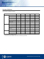
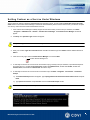
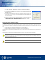

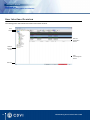
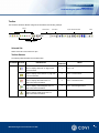
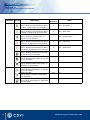
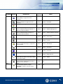
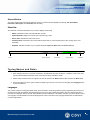

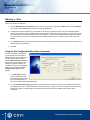
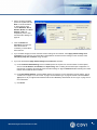
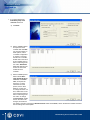
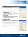
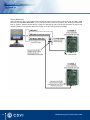
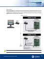
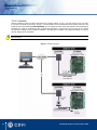
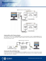
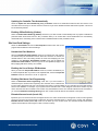
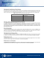
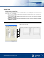
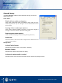
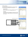
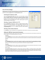
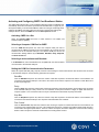
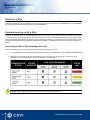
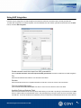
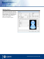
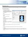
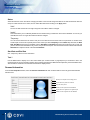
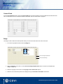

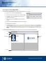
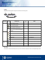
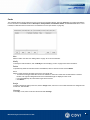
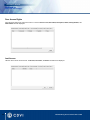
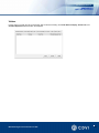
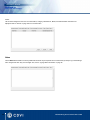

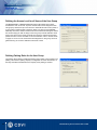
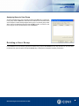
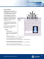
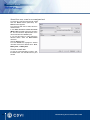
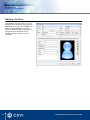
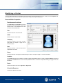
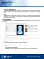
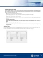
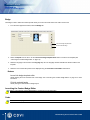
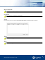
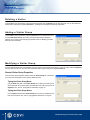
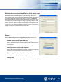
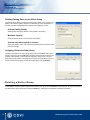
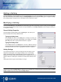

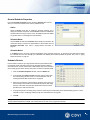
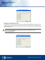


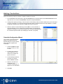
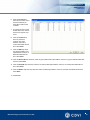
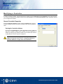
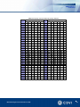
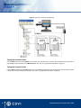
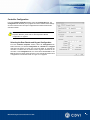
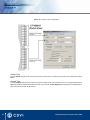
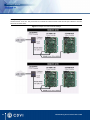
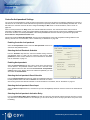
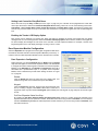
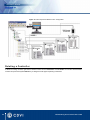

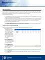
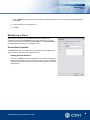
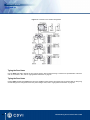
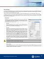
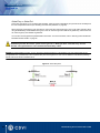
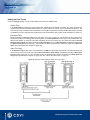
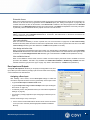
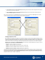
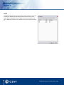
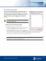
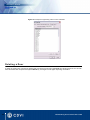
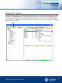

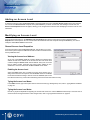
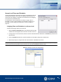
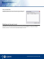
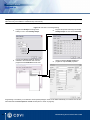
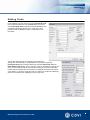
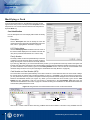

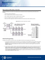
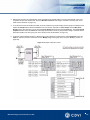

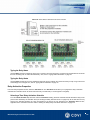
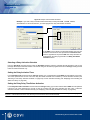

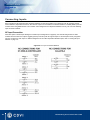
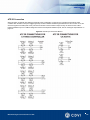
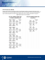
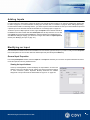
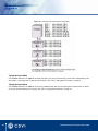
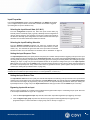
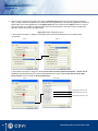
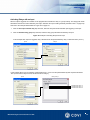
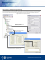
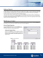
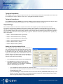
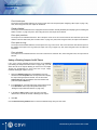

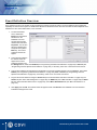
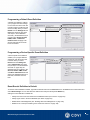
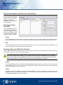
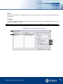
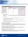
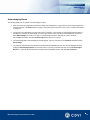
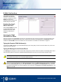
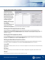
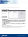
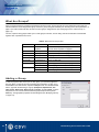
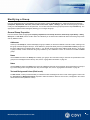
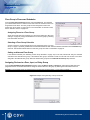
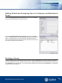
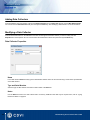
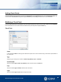
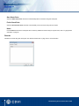
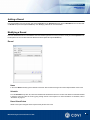
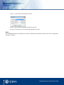
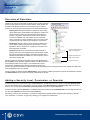
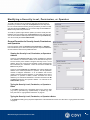
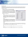
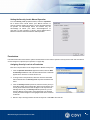
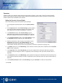
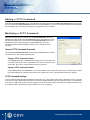
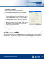

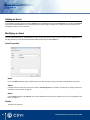
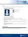

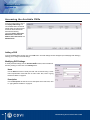
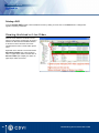
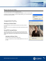
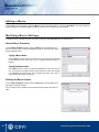
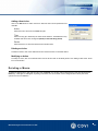

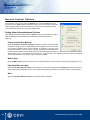
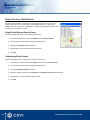
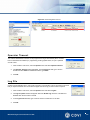


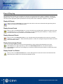
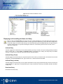
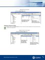
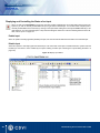
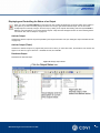
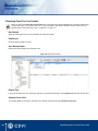
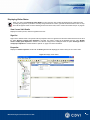
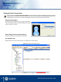
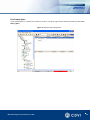

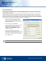
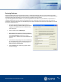
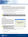

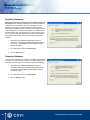
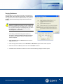
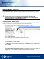

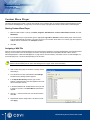
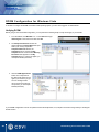
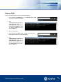
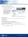
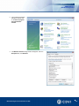
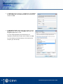
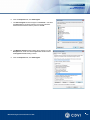
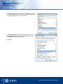
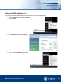
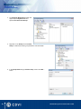
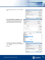
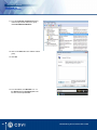
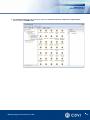
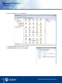
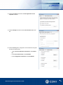
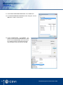
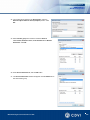
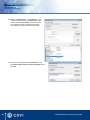
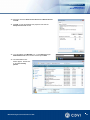
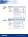

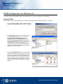
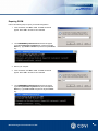
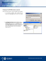
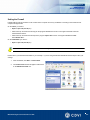
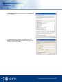
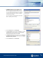
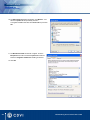
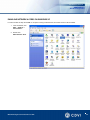
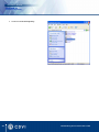
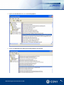
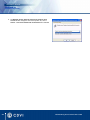
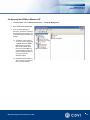
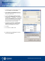
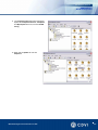
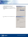
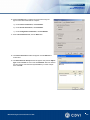
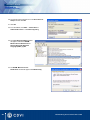
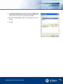
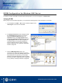
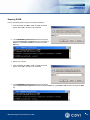
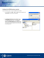
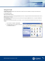
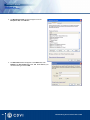
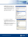
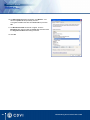
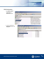
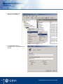
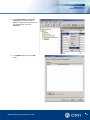
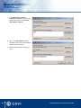
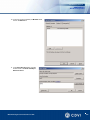
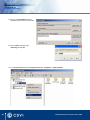
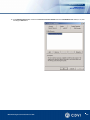
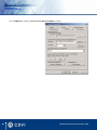
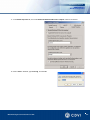
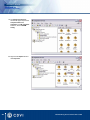
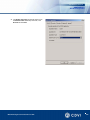
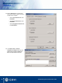
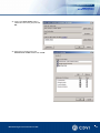
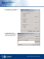
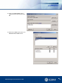
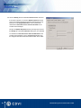
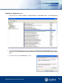
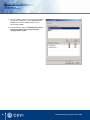
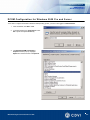
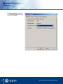
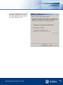
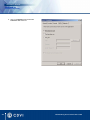
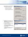
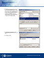


![[ ] playback mode](http://vs1.manualzilla.com/store/data/005894332_1-eb04455062e124c285a30d79ed1ad6c3-150x150.png)


![DGID Software [EN]](http://vs1.manualzilla.com/store/data/005717670_1-65b44a14cec330296683d17d94da3fca-150x150.png)