1
UM1011
User manual
STM32100E-EVAL demonstration firmware
Introduction
This user manual describes the demonstration firmware running on the STM32100E-EVAL
evaluation board, which can be used to evaluate the capabilities of the high-density value
line STM32F100ZET6 microcontroller and on-board peripherals.
This demo contains many applications that can be easily reused, such as RTC calendar, file
system FAT implementation on SD Card, Waveplayer with STM32 DAC peripheral, HDMI
CEC networking demo with an infrared remote control capability, temperature sensor
interfacing and TFT LCD with touch screen.
The STM32100E-EVAL board is delivered with the demonstration programmed in the
internal Flash memory, and all the files needed by the demonstration are programmed in the
MicroSD card. At each reset (board power-up, external reset, etc.), the demonstration is
executed.
In case the STM32100E-EVAL board was not factory-programmed or the demonstration
application was erased, the in-circuit programming (ICP) boot loader can be used to
program this file. For more details, refer to Section 3: STM32100E-EVAL demonstration
package and Section 4: STM32100E-EVAL demonstration programming.
This demonstration firmware is available for download from the STMicroelectronics website:
www.st.com.
April 2011
Doc ID 18064 Rev 1
1/49
www.st.com
Contents
UM1011
Contents
1
Evaluation board overview . . . . . . . . . . . . . . . . . . . . . . . . . . . . . . . . . . . . 7
1.1
Power control . . . . . . . . . . . . . . . . . . . . . . . . . . . . . . . . . . . . . . . . . . . . . . . 8
1.2
Clocking . . . . . . . . . . . . . . . . . . . . . . . . . . . . . . . . . . . . . . . . . . . . . . . . . . . 8
1.3
Reset control . . . . . . . . . . . . . . . . . . . . . . . . . . . . . . . . . . . . . . . . . . . . . . . 8
1.4
Debugging JTAG interface . . . . . . . . . . . . . . . . . . . . . . . . . . . . . . . . . . . . . 8
1.5
Serial wire debugger interface . . . . . . . . . . . . . . . . . . . . . . . . . . . . . . . . . . 8
1.6
Embedded ST-LINK . . . . . . . . . . . . . . . . . . . . . . . . . . . . . . . . . . . . . . . . . . 8
1.7
Display devices . . . . . . . . . . . . . . . . . . . . . . . . . . . . . . . . . . . . . . . . . . . . . . 8
1.8
1.7.1
LCD . . . . . . . . . . . . . . . . . . . . . . . . . . . . . . . . . . . . . . . . . . . . . . . . . . . . . 8
1.7.2
LEDs . . . . . . . . . . . . . . . . . . . . . . . . . . . . . . . . . . . . . . . . . . . . . . . . . . . . 8
Interfaces . . . . . . . . . . . . . . . . . . . . . . . . . . . . . . . . . . . . . . . . . . . . . . . . . . 9
1.8.1
2
1.9
Motor control . . . . . . . . . . . . . . . . . . . . . . . . . . . . . . . . . . . . . . . . . . . . . . . 9
1.10
IrDA . . . . . . . . . . . . . . . . . . . . . . . . . . . . . . . . . . . . . . . . . . . . . . . . . . . . . . 9
1.11
Miscellaneous peripherals . . . . . . . . . . . . . . . . . . . . . . . . . . . . . . . . . . . . . 9
1.11.1
Joystick . . . . . . . . . . . . . . . . . . . . . . . . . . . . . . . . . . . . . . . . . . . . . . . . . . 9
1.11.2
Push-buttons . . . . . . . . . . . . . . . . . . . . . . . . . . . . . . . . . . . . . . . . . . . . . . 9
1.11.3
12-bit analog-to-digital converter (ADC) . . . . . . . . . . . . . . . . . . . . . . . . . 9
1.11.4
Audio amplifier . . . . . . . . . . . . . . . . . . . . . . . . . . . . . . . . . . . . . . . . . . . . . 9
1.11.5
Storage memories . . . . . . . . . . . . . . . . . . . . . . . . . . . . . . . . . . . . . . . . . . 9
1.11.6
Temperature sensor . . . . . . . . . . . . . . . . . . . . . . . . . . . . . . . . . . . . . . . . 10
Running the demonstration . . . . . . . . . . . . . . . . . . . . . . . . . . . . . . . . . . 11
2.1
Menu tree and navigation . . . . . . . . . . . . . . . . . . . . . . . . . . . . . . . . . . . . . 11
2.2
Demonstration startup . . . . . . . . . . . . . . . . . . . . . . . . . . . . . . . . . . . . . . . 12
2.3
Time and date configuration . . . . . . . . . . . . . . . . . . . . . . . . . . . . . . . . . . . 14
2.4
Menu navigation . . . . . . . . . . . . . . . . . . . . . . . . . . . . . . . . . . . . . . . . . . . . 14
2.4.1
2.5
2.6
2/49
RS232 . . . . . . . . . . . . . . . . . . . . . . . . . . . . . . . . . . . . . . . . . . . . . . . . . . . 9
Navigation procedure . . . . . . . . . . . . . . . . . . . . . . . . . . . . . . . . . . . . . . . 15
Clock sources . . . . . . . . . . . . . . . . . . . . . . . . . . . . . . . . . . . . . . . . . . . . . . 16
2.5.1
Clock control . . . . . . . . . . . . . . . . . . . . . . . . . . . . . . . . . . . . . . . . . . . . . 16
2.5.2
Clock failure . . . . . . . . . . . . . . . . . . . . . . . . . . . . . . . . . . . . . . . . . . . . . . 17
STM32F100ZET6 resources . . . . . . . . . . . . . . . . . . . . . . . . . . . . . . . . . . 18
Doc ID 18064 Rev 1
UM1011
Contents
2.7
3
4
2.6.1
Peripherals . . . . . . . . . . . . . . . . . . . . . . . . . . . . . . . . . . . . . . . . . . . . . . . 18
2.6.2
Interrupts . . . . . . . . . . . . . . . . . . . . . . . . . . . . . . . . . . . . . . . . . . . . . . . . 19
2.6.3
External interrupts . . . . . . . . . . . . . . . . . . . . . . . . . . . . . . . . . . . . . . . . . 20
2.6.4
Internal memory organization . . . . . . . . . . . . . . . . . . . . . . . . . . . . . . . . 20
2.6.5
External memory organization . . . . . . . . . . . . . . . . . . . . . . . . . . . . . . . . 20
Demonstration applications . . . . . . . . . . . . . . . . . . . . . . . . . . . . . . . . . . . 22
2.7.1
Product presentation . . . . . . . . . . . . . . . . . . . . . . . . . . . . . . . . . . . . . . . 22
2.7.2
Calendar . . . . . . . . . . . . . . . . . . . . . . . . . . . . . . . . . . . . . . . . . . . . . . . . 24
2.7.3
Image Viewer submenu . . . . . . . . . . . . . . . . . . . . . . . . . . . . . . . . . . . . . 29
2.7.4
Wave Player submenu . . . . . . . . . . . . . . . . . . . . . . . . . . . . . . . . . . . . . . 30
2.7.5
Low power modes . . . . . . . . . . . . . . . . . . . . . . . . . . . . . . . . . . . . . . . . . 32
2.7.6
Infrared decoding . . . . . . . . . . . . . . . . . . . . . . . . . . . . . . . . . . . . . . . . . . 37
2.7.7
Thermometer . . . . . . . . . . . . . . . . . . . . . . . . . . . . . . . . . . . . . . . . . . . . . 38
2.7.8
HDMI™ CEC submenu . . . . . . . . . . . . . . . . . . . . . . . . . . . . . . . . . . . . . 39
2.7.9
Help submenu . . . . . . . . . . . . . . . . . . . . . . . . . . . . . . . . . . . . . . . . . . . . 42
2.7.10
About submenu . . . . . . . . . . . . . . . . . . . . . . . . . . . . . . . . . . . . . . . . . . . 43
STM32100E-EVAL demonstration package . . . . . . . . . . . . . . . . . . . . . . 44
3.1
Libraries . . . . . . . . . . . . . . . . . . . . . . . . . . . . . . . . . . . . . . . . . . . . . . . . . . 45
3.2
Project . . . . . . . . . . . . . . . . . . . . . . . . . . . . . . . . . . . . . . . . . . . . . . . . . . . 45
3.3
Utilities . . . . . . . . . . . . . . . . . . . . . . . . . . . . . . . . . . . . . . . . . . . . . . . . . . . 45
STM32100E-EVAL demonstration programming . . . . . . . . . . . . . . . . . 46
4.1
Programming the media files . . . . . . . . . . . . . . . . . . . . . . . . . . . . . . . . . . 46
4.2
Programming the demonstration . . . . . . . . . . . . . . . . . . . . . . . . . . . . . . . 46
4.2.1
5
Using IAP . . . . . . . . . . . . . . . . . . . . . . . . . . . . . . . . . . . . . . . . . . . . . . . . 47
Revision history . . . . . . . . . . . . . . . . . . . . . . . . . . . . . . . . . . . . . . . . . . . 48
Doc ID 18064 Rev 1
3/49
List of tables
UM1011
List of tables
Table 1.
Table 2.
Table 3.
Table 4.
4/49
STM32F100ZET6 demonstration peripherals. . . . . . . . . . . . . . . . . . . . . . . . . . . . . . . . . . . 18
STM32F100ZET6 demonstration interrupts . . . . . . . . . . . . . . . . . . . . . . . . . . . . . . . . . . . . 19
STM32F100ZET6 demonstration external interrupts . . . . . . . . . . . . . . . . . . . . . . . . . . . . . 20
Document revision history . . . . . . . . . . . . . . . . . . . . . . . . . . . . . . . . . . . . . . . . . . . . . . . . . 48
Doc ID 18064 Rev 1
UM1011
List of figures
List of figures
Figure 1.
Figure 2.
Figure 3.
Figure 4.
Figure 5.
Figure 6.
Figure 7.
Figure 8.
Figure 9.
Figure 10.
Figure 11.
Figure 12.
Figure 13.
Figure 14.
Figure 15.
Figure 16.
Figure 17.
Figure 18.
Figure 19.
Figure 20.
Figure 21.
Figure 22.
Figure 23.
Figure 24.
Figure 25.
Figure 26.
Figure 27.
Figure 28.
Figure 29.
Figure 30.
Figure 31.
Figure 32.
Figure 33.
Figure 34.
Figure 35.
Figure 36.
Figure 37.
Figure 38.
Figure 39.
Figure 40.
Figure 41.
Figure 42.
Figure 43.
Figure 44.
Figure 45.
Figure 46.
Figure 47.
Figure 48.
Evaluation board overview . . . . . . . . . . . . . . . . . . . . . . . . . . . . . . . . . . . . . . . . . . . . . . . . . . 7
Structure of the demonstration menus . . . . . . . . . . . . . . . . . . . . . . . . . . . . . . . . . . . . . . . . 12
SD Card check . . . . . . . . . . . . . . . . . . . . . . . . . . . . . . . . . . . . . . . . . . . . . . . . . . . . . . . . . . 13
Warning message . . . . . . . . . . . . . . . . . . . . . . . . . . . . . . . . . . . . . . . . . . . . . . . . . . . . . . . . 13
ST logo . . . . . . . . . . . . . . . . . . . . . . . . . . . . . . . . . . . . . . . . . . . . . . . . . . . . . . . . . . . . . . . . 13
STM32 presentation slide . . . . . . . . . . . . . . . . . . . . . . . . . . . . . . . . . . . . . . . . . . . . . . . . . . 14
Time and date configuration . . . . . . . . . . . . . . . . . . . . . . . . . . . . . . . . . . . . . . . . . . . . . . . . 14
Application main menu . . . . . . . . . . . . . . . . . . . . . . . . . . . . . . . . . . . . . . . . . . . . . . . . . . . 15
Application submenus. . . . . . . . . . . . . . . . . . . . . . . . . . . . . . . . . . . . . . . . . . . . . . . . . . . . . 15
Navigating in the demonstration menus . . . . . . . . . . . . . . . . . . . . . . . . . . . . . . . . . . . . . . . 16
Clock tree diagram . . . . . . . . . . . . . . . . . . . . . . . . . . . . . . . . . . . . . . . . . . . . . . . . . . . . . . . 17
No HSE clock detected . . . . . . . . . . . . . . . . . . . . . . . . . . . . . . . . . . . . . . . . . . . . . . . . . . . . 17
Standby mode entered . . . . . . . . . . . . . . . . . . . . . . . . . . . . . . . . . . . . . . . . . . . . . . . . . . . . 18
Internal Flash memory organization . . . . . . . . . . . . . . . . . . . . . . . . . . . . . . . . . . . . . . . . . . 20
MicroSD Card organization. . . . . . . . . . . . . . . . . . . . . . . . . . . . . . . . . . . . . . . . . . . . . . . . . 21
Card removal . . . . . . . . . . . . . . . . . . . . . . . . . . . . . . . . . . . . . . . . . . . . . . . . . . . . . . . . . . . 22
Product presentation is ready to start . . . . . . . . . . . . . . . . . . . . . . . . . . . . . . . . . . . . . . . . . 22
First presentation slide . . . . . . . . . . . . . . . . . . . . . . . . . . . . . . . . . . . . . . . . . . . . . . . . . . . . 23
Last presentation slide . . . . . . . . . . . . . . . . . . . . . . . . . . . . . . . . . . . . . . . . . . . . . . . . . . . . 23
No loaded wave file . . . . . . . . . . . . . . . . . . . . . . . . . . . . . . . . . . . . . . . . . . . . . . . . . . . . . . 24
End of slide show . . . . . . . . . . . . . . . . . . . . . . . . . . . . . . . . . . . . . . . . . . . . . . . . . . . . . . . . 24
Setting the time and date . . . . . . . . . . . . . . . . . . . . . . . . . . . . . . . . . . . . . . . . . . . . . . . . . . 25
Time Adjust submenu . . . . . . . . . . . . . . . . . . . . . . . . . . . . . . . . . . . . . . . . . . . . . . . . . . . . . 25
Time Show submenu . . . . . . . . . . . . . . . . . . . . . . . . . . . . . . . . . . . . . . . . . . . . . . . . . . . . . 26
Setting the year. . . . . . . . . . . . . . . . . . . . . . . . . . . . . . . . . . . . . . . . . . . . . . . . . . . . . . . . . . 26
Setting the month . . . . . . . . . . . . . . . . . . . . . . . . . . . . . . . . . . . . . . . . . . . . . . . . . . . . . . . . 27
Setting the day of the month . . . . . . . . . . . . . . . . . . . . . . . . . . . . . . . . . . . . . . . . . . . . . . . . 27
Date Show submenu . . . . . . . . . . . . . . . . . . . . . . . . . . . . . . . . . . . . . . . . . . . . . . . . . . . . . 27
Setting the alarm activation time. . . . . . . . . . . . . . . . . . . . . . . . . . . . . . . . . . . . . . . . . . . . . 28
Alarm Show submenu. . . . . . . . . . . . . . . . . . . . . . . . . . . . . . . . . . . . . . . . . . . . . . . . . . . . . 28
Time and date not configured . . . . . . . . . . . . . . . . . . . . . . . . . . . . . . . . . . . . . . . . . . . . . . . 29
Image Viewer submenu . . . . . . . . . . . . . . . . . . . . . . . . . . . . . . . . . . . . . . . . . . . . . . . . . . . 29
Wave Player submenu . . . . . . . . . . . . . . . . . . . . . . . . . . . . . . . . . . . . . . . . . . . . . . . . . . . . 30
Wave Player interface. . . . . . . . . . . . . . . . . . . . . . . . . . . . . . . . . . . . . . . . . . . . . . . . . . . . . 30
Wave Player Playing submenu . . . . . . . . . . . . . . . . . . . . . . . . . . . . . . . . . . . . . . . . . . . . . . 31
Pause submenu . . . . . . . . . . . . . . . . . . . . . . . . . . . . . . . . . . . . . . . . . . . . . . . . . . . . . . . . . 31
Stop mode menu . . . . . . . . . . . . . . . . . . . . . . . . . . . . . . . . . . . . . . . . . . . . . . . . . . . . . . . . 32
Stop mode entered . . . . . . . . . . . . . . . . . . . . . . . . . . . . . . . . . . . . . . . . . . . . . . . . . . . . . . . 32
MCU in Stop mode . . . . . . . . . . . . . . . . . . . . . . . . . . . . . . . . . . . . . . . . . . . . . . . . . . . . . . . 33
RTC Alarm wakes up the MCU from Stop mode . . . . . . . . . . . . . . . . . . . . . . . . . . . . . . . . 33
Setting the wakeup time . . . . . . . . . . . . . . . . . . . . . . . . . . . . . . . . . . . . . . . . . . . . . . . . . . . 33
RTC Alarm wakeup configured . . . . . . . . . . . . . . . . . . . . . . . . . . . . . . . . . . . . . . . . . . . . . . 34
RTC Alarm wakeup. . . . . . . . . . . . . . . . . . . . . . . . . . . . . . . . . . . . . . . . . . . . . . . . . . . . . . . 34
Time and Date configuration prompt . . . . . . . . . . . . . . . . . . . . . . . . . . . . . . . . . . . . . . . . . 34
Entering Standby mode . . . . . . . . . . . . . . . . . . . . . . . . . . . . . . . . . . . . . . . . . . . . . . . . . . . 35
MCU in Standby mode . . . . . . . . . . . . . . . . . . . . . . . . . . . . . . . . . . . . . . . . . . . . . . . . . . . . 35
Setting the wakeup time . . . . . . . . . . . . . . . . . . . . . . . . . . . . . . . . . . . . . . . . . . . . . . . . . . . 36
RTC Alarm wakeup configured . . . . . . . . . . . . . . . . . . . . . . . . . . . . . . . . . . . . . . . . . . . . . . 36
Doc ID 18064 Rev 1
5/49
List of figures
Figure 49.
Figure 50.
Figure 51.
Figure 52.
Figure 53.
Figure 54.
Figure 55.
Figure 56.
Figure 57.
Figure 58.
Figure 59.
Figure 60.
Figure 61.
Figure 62.
Figure 63.
Figure 64.
Figure 65.
Figure 66.
6/49
UM1011
Time and Date configuration prompt . . . . . . . . . . . . . . . . . . . . . . . . . . . . . . . . . . . . . . . . . 36
Infrared Decoding menu . . . . . . . . . . . . . . . . . . . . . . . . . . . . . . . . . . . . . . . . . . . . . . . . . . . 37
Infrared protocol submenu . . . . . . . . . . . . . . . . . . . . . . . . . . . . . . . . . . . . . . . . . . . . . . . . . 37
Thermometer submenu selected . . . . . . . . . . . . . . . . . . . . . . . . . . . . . . . . . . . . . . . . . . . . 38
Temperature display . . . . . . . . . . . . . . . . . . . . . . . . . . . . . . . . . . . . . . . . . . . . . . . . . . . . . . 38
Warning temperature display . . . . . . . . . . . . . . . . . . . . . . . . . . . . . . . . . . . . . . . . . . . . . . . 39
Temperature sensor error . . . . . . . . . . . . . . . . . . . . . . . . . . . . . . . . . . . . . . . . . . . . . . . . . . 39
HDMI CEC submenu selected . . . . . . . . . . . . . . . . . . . . . . . . . . . . . . . . . . . . . . . . . . . . . . 40
HDMI CEC configuration submenu. . . . . . . . . . . . . . . . . . . . . . . . . . . . . . . . . . . . . . . . . . . 40
CEC menu . . . . . . . . . . . . . . . . . . . . . . . . . . . . . . . . . . . . . . . . . . . . . . . . . . . . . . . . . . . . . 40
Select CEC command . . . . . . . . . . . . . . . . . . . . . . . . . . . . . . . . . . . . . . . . . . . . . . . . . . . . 41
Receive subscreen information . . . . . . . . . . . . . . . . . . . . . . . . . . . . . . . . . . . . . . . . . . . . . 41
Help submenu. . . . . . . . . . . . . . . . . . . . . . . . . . . . . . . . . . . . . . . . . . . . . . . . . . . . . . . . . . . 42
Joystick push-buttons . . . . . . . . . . . . . . . . . . . . . . . . . . . . . . . . . . . . . . . . . . . . . . . . . . . . . 42
Second Help slide . . . . . . . . . . . . . . . . . . . . . . . . . . . . . . . . . . . . . . . . . . . . . . . . . . . . . . . . 43
About submenu. . . . . . . . . . . . . . . . . . . . . . . . . . . . . . . . . . . . . . . . . . . . . . . . . . . . . . . . . . 43
STM32100E-EVAL demonstration package directory tree . . . . . . . . . . . . . . . . . . . . . . . . . 44
SD Card directory organization. . . . . . . . . . . . . . . . . . . . . . . . . . . . . . . . . . . . . . . . . . . . . . 46
Doc ID 18064 Rev 1
UM1011
1
Evaluation board overview
Evaluation board overview
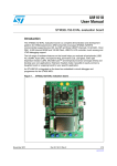
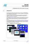
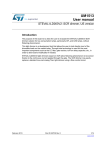
The STM32100E-EVAL evaluation board provides a development and demonstration
platform for STM32F100Zx-based applications. It is used to evaluate the major functions of
the STM32F100ZET6 microcontroller.
Figure 1 summarizes the main functional blocks of the evaluation board.
Figure 1.
Evaluation board overview
)2RECEIVER
4)-?#(
-"YTE
32!-BIT
/NE.!.$
($-)
CONNE CTOR
3ERIAL&LASH
30)
-ICRO3$
CARD
53!24
)R$!
TRANSCEIVER
53!24
23
TRANSCEIVER
53!24
23
TRANSCEIVER
53!24
23
TRANSCEIVER
&3-#
4&4
,#$
($-)
CONNECTOR
30)
)#
#%#
34-&:%4
'0)/
%%02/-
"UTTONS
)#
0OTENTIOMETER
!$#
".#
CONNECTOR
-OTOR CONTROL
CONNECTOR
53!24
$"CONNECTOR
,#$TOUCH
SCREEN
*OYSTICK
,%$S
53!24
$"CONNECTOR
4EM PERATURE
SENSOR
$!#
3PEAKER
AMPLIFIER
*4!'
%MBEDDED
34 ,).+
-#
53"4YPE "
CONNECTOR
*4! 'TRACE
CONNECTOR
6
REGULATOR
%XTENSION
CONNECTORFOR
'0)/S
-36
Doc ID 18064 Rev 1
7/49
Evaluation board overview
1.1
UM1011
Power control
The evaluation board can be powered from an external 5 V supply or from the USB
connector. All other required voltages are provided by on-board voltage regulators.
1.2
Clocking
Two clock sources are available on the STM32100E-EVAL evaluation board:
1.3
●
32 kHz crystal for embedded RTC
●
8 MHz crystal for the STM32F100ZET6 main clock system
Reset control
The reset can be generated by hardware or software:
1.4
●
Reset button: activates the RESET input when pressed
●
JTAG reset
Debugging JTAG interface
Software debug is done via the standard ARM® JTAG interface, a 20-pin IDC (insulation
displacement connector) for connection to the standard ARM host interface.
1.5
Serial wire debugger interface
The serial wire debug port (SWD-DP) provides a 2-pin (clock + data) interface to the AHPAP port.
1.6
Embedded ST-LINK
The ST-LINK in-circuit debugger/programmer is embedded on the board. It supports the
STM32F100ZET6 MCU.
1.7
Display devices
1.7.1
LCD
A color LCD module is mounted on the STM32100E-EVAL board. It is interfaced through
FSMC of STM32F100ZET6.
1.7.2
LEDs
Four general-purpose LEDs are available.
8/49
Doc ID 18064 Rev 1
UM1011
Evaluation board overview
1.8
Interfaces
1.8.1
RS232
The STM32F100ZET6 evaluation board (STM32100E-EVAL) provides two on-board RS232
serial ports. Both RS232 ports are accessed via DB9 connectors.
1.9
Motor control
The STM32100E-EVAL evaluation board supports inductor motor control via a 34-pin
connector. This connector provides all required control and feedback signals to and from the
motor power-driving board.
1.10
IrDA
The STM32100E-EVAL evaluation board supports IrDA communication. The interface is
mounted on UART4.
1.11
Miscellaneous peripherals
1.11.1
Joystick
The board features a four-direction joystick with a selection key.
1.11.2
Push-buttons
The following push-buttons are available:
1.11.3
●
Key
●
Tamper
●
Wakeup: used to wake up the processor from low power mode
12-bit analog-to-digital converter (ADC)
The MCU ADC channel (ADC1_IN14) is connected to an on-board variable resistor. The
variable resistor provides a voltage in the range of 0 V to 3.3 V.
Moreover, a BNC connector is available for analog input.
1.11.4
Audio amplifier
The STM32100E-EVAL evaluation board implements a dedicated audio amplifier which can
be interfaced with the STM32 DAC peripheral. For the audio output, a speaker and an audio
jack connector are available on the board and connected to the DAC.
1.11.5
Storage memories
The STM32100E-EVAL evaluation board features an 8 Mbyte SPI Flash memory and an
SD Card™ memory connected to the SPI2 peripheral. It features also an 64 Kbyte I2C
EEPROM memory connected to I2C2.
Doc ID 18064 Rev 1
9/49
Evaluation board overview
1.11.6
UM1011
Temperature sensor
The STM32100E-EVAL evaluation board includes an I2C temperature sensor connected to
the I2C2 peripheral.
10/49
Doc ID 18064 Rev 1
UM1011
Running the demonstration
2
Running the demonstration
2.1
Menu tree and navigation
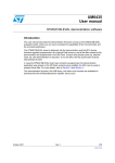
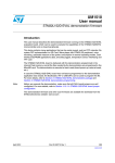
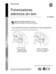
Figure 2 shows the menu system of the STM32F100ZET6 demonstration. The main menu is
shown on the left-hand side. The UP, DOWN, RIGHT and LEFT joystick directions allow the
user to navigate between items in the main menu and the submenus.
The user can also navigate through the demonstration menu by using the touch screen.The
touch screen works only at the first level of the demonstration (main menu).
To enter a submenu, press the SEL push-button. The SEL push-button designates the
action of vertically pressing the top of the joystick, as opposed to moving it horizontally UP,
DOWN, RIGHT or LEFT.
To exit a submenu, select the Return menu and press SEL.
Doc ID 18064 Rev 1
11/49
Running the demonstration
Figure 2.
UM1011
Structure of the demonstration menus
0RODUCT
PRESENTATION
3TART
!DJUST
2ETURN
3HOW
4IME
#ALENDAR
$ATE
!LARM
2ETURN
)MAGE
6IEWER
7AVE0LAYER
)MAGE6IEWER
3TANDBY
2ETURN
4HERMOMETER
3HOW
2ETURN
!DJUST
3HOW
2ETURN
7AVE0LAYER
3TOP
,OWPOWER
MODE
!DJUST
2ETURN
2ETURN
-AINMENU
2ETURN
4EMPERATURE
%XIT%84)
%XIT24#ALARM
2ETURN
%XITWAKEUPPIN
%XIT24#ALARM
2ETURN
2ETURN
($-)#%#
($-)#%#
2ETURN
0HILIPS2#
)NFRARED
DECODING
3)2#
2ETURN
(ELP
3TART
3HOW
2ETURN
3HOW
2ETURN
3HOW
2ETURN
2ETURN
!BOUT
!BOUT
2ETURN
-36
2.2
Demonstration startup
The demonstration starts after a board reset. The system checks if an SD memory card is
already plugged into the connector CN6. If no card detected, the demonstration does not
start and the message shown in Figure 3 is displayed on the LCD screen.
12/49
Doc ID 18064 Rev 1
UM1011
Running the demonstration
Figure 3.
SD Card check
Please insert SD Card
To continue the demonstration, insert an SD Card. The demonstration graphic icons and
bitmap files are now checked in the MicroSD Card (see Section 2.6.5: External memory
organization). All the icons have to be correctly programmed in the MicroSD Card for the
demonstration to start. If an icon is missing, the demonstration does not start and the
message shown in Figure 4 is displayed on the LCD screen.
Figure 4.
Warning message
Warning
No loaded Bitmap
files. Demo cannot be
executed.
Please be sure that
all files are
correctly programmed
in the MicroSD card
and restart the demo
If the icons are correctly loaded into the SD Card memory, the welcome screen is displayed
and the ST logo appears on the LCD screen:
Figure 5.
ST logo
Doc ID 18064 Rev 1
13/49
Running the demonstration
UM1011
After some seconds, the following STM32 slide is displayed on the LCD screen:
Figure 6.
2.3
STM32 presentation slide
Time and date configuration
When the board is powered up for the first time and no power supply is detected on VBAT
(battery), you are prompted to set the time, year, month and day. The following message
appears on the LCD screen.
Figure 7.
Time and date configuration
To set the time and date, press the SEL push-button. The Time Adjust and Date Adjust
menus are displayed. Use the joystick UP/DOWN and SEL push-buttons to set the
time/date.
To ignore the configuration sequence, press any key except for the SEL push-button.The
main menu is displayed.
Note:
2.4
1
You can set the time parameters at any time by using the Calendar menu (see
Section 2.7.2: Calendar).
2
If the time has already been configured, then the number of elapsed days (higher than
1 day) since the last time the demonstration board was powered up appears on the LCD
screen. It is soon followed by the current date.
Menu navigation
Once the time/date have been set, the main menu appears. The main menu is displayed in
the form of a set of icons. It shows all the submenus in the same screen. You can navigate
through the submenus by pressing the joystick UP, DOWN, RIGHT and LEFT. To enter the
desired submenu, press the SEL joystick push-button or push on the desired icon, and the
submenu corresponding to the selected icon is displayed.
14/49
Doc ID 18064 Rev 1
UM1011
Running the demonstration
Figure 8.
Application main menu
APP Main Menu Name
Note:
The icons shown in Figure 8 are taken from
http://commons.wikimedia.org/wiki/Crystal_Clear.
Once a submenu has been selected, the name of the application is listed at the top of the
display and all the corresponding submenus are listed below as shown in Figure 9.
Figure 9.
2.4.1
Application submenus
Navigation procedure
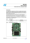
The demonstration menu is based on circular navigation, submenu selection, item selection
and back navigation.
To navigate through the demonstration menus, use the joystick push-buttons located on the
evaluation board: RIGHT, LEFT, UP, DOWN and SEL.
●
The UP, DOWN, RIGHT and LEFT push-buttons are used to perform circular navigation
in the main menu and the current menu items.
●
TOUCH SCREEN is used also to perform navigation only in the main menu.
●
The SEL push-button selects the current item.
●
The UP and DOWN push-buttons are used for vertical navigation in the submenus.
To return to the upper menu, go to the Return menu and press SEL.
Doc ID 18064 Rev 1
15/49
Running the demonstration
UM1011
,EFT
$OWN
)TEM
5P
5P
2IGHT
2IGHT
2IGHT
)TEM
,EFT
)TEM
,EFT
)TEM 2IGHT
,EFT
$OWN
$OWN
)TEM
2IGHT
5P
)TEM
,EFT
2IGHT
5P
$OWN
5P
5P
2IGHT
$OWN
2IGHT
)TEM
)TEM
,EFT
5P
)TEM
,EFT
2IGHT
)TEM
,EFT
5P
,EFT
2IGHT
$OWN
5P
)TEM
2IGHT
$OWN
)TEM
$OWN
,EFT
5P
,EFT
$OWN
2IGHT
$OWN
)TEM
$OWN
,EFT
5P
5P
Figure 10. Navigating in the demonstration menus
$OWN
3ELECT
)TEM
ECT
L
3E
3EL
)TEM
ECT
)TEM
)TEM
)TEMN
)TEMN
2ETURN
2ETURN
AI
2.5
Clock sources
2.5.1
Clock control
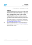
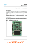
The STM32F100ZET6 internal clocks are derived from the HSE clocked by the external
8 MHz crystal.
In this demonstration application, the various system clocks are configured as follows:
●
The system clock is set to 24 MHz. The PLL is used as the system clock source:
24 MHz.
●
The HCLK frequency is set to 24 MHz.
●
The timer clock (TIMCLK) is set to 24 MHz.
●
PCLK1 is set to 24 MHz.
●
PCLK2 is set to 24 MHz.
Only the RTC is clocked by a 32 kHz external oscillator.
Figure 11 illustrates the clock tree organization for this demonstration.
16/49
Doc ID 18064 Rev 1
UM1011
Running the demonstration
!0"PRESCALER
(3%
02%$)6
0,,
393#,+ !("PRESCALER
-ULTIPLICATORX -(ZX
-(Z
0#,+TO!0"
PERIPHERALS
-(Z
4)-
§IF!0"PRESCALER
ELSE§MULTIPLIER
-(Z
-(ZMAX
!0"PRESCALER
,3%
OSCILLATOR
K(Z
-(Z
(3%
OSCILLATOR
-(Z
Figure 11. Clock tree diagram
-(Z
0#,+TO!0"
PERIPHERALS
4)-
§IF!0"PRESCALER
ELSE§MULTIPLIER
-(Z
24#
K(Z
AI
2.5.2
Clock failure
At any point of the demonstration, if no clock is present on OSC_IN (broken or disconnected
crystal), the message shown in Figure 12 is displayed on the LCD screen.
Figure 12. No HSE clock detected
If no clock is detected, the clock security system (CSS) feeds the MCU with the HSI OSC
used as an emergency clock.
The demonstration will not restart as long as the 8 MHz crystal is not present. You must
connect the crystal before starting the demonstration. Connecting the 8 MHz crystal after
reset may not restart the demonstration correctly.
If the 8 MHz crystal is not reconnected in the next few seconds, the MCU enters Standby
mode. If the 8 MHz crystal is reconnected within a few seconds, a system reset is
generated.
When a timeout occurs, the MCU enters Standby mode and the message shown in
Figure 13 is displayed on the LCD screen.
Doc ID 18064 Rev 1
17/49
Running the demonstration
UM1011
Figure 13. Standby mode entered
2.6
STM32F100ZET6 resources
2.6.1
Peripherals
All used peripherals are described in Table 1.
Table 1.
STM32F100ZET6 demonstration peripherals
Used peripherals
18/49
Applications
I2C2
Temperature sensor
BKP
Calendar + demo kernel
EXTI
Menu navigation + joystick + push-button + low power modes
GPIO
All applications + LEDs
NVIC
All applications using interrupts
PWR
Low power modes
RCC
All applications + demo kernel
RTC
Calendar
FSMC
Color LCD
SysTick
Generate 10 ms time base
TIM1
LED toggling
DMA2
Wave Player
TIM6
Wave Player
DAC
Wave Player
SPI1
SPI Flash
SPI2
MSD
TIM3
Infrared decoding
CEC
HDMI-CEC
Doc ID 18064 Rev 1
UM1011
2.6.2
Running the demonstration
Interrupts
Table 2 shows all the enabled interrupts.
Table 2.
STM32F100ZET6 demonstration interrupts
Interrupts
Priority
Used for
SysTick
Preemption: 0
SubPriority: 0
System timing
RTC
Preemption: 0
SubPriority: 0
Calendar, date update
NMI
Preemption(fixed): -2
CSS interrupt
EXTI0
Preemption: 2
SubPriority: 1
Menu navigation
EXTI9_5
Preemption: 2
SubPriority: 1
Menu navigation
EXTI15_10
Preemption: 0
SubPriority: 0
Menu navigation
I2C2 Error
Preemption: 0
SubPriority: 0
SMBus Alert interrupt
TIM6_UP
Preemption: 0
SubPriority: 1
Sampling rate
TIM1_UP
Preemption: 1
SubPriority: 3
LED toggling
RTC Alarm
Preemption: 0
SubPriority: 1
Alarm generation
TIM3_IRQ
Preemption: 1
SubPriority: 0
Infrared decoding
CEC
Preemption: 1
SubPriority: 1
CEC transactions
Doc ID 18064 Rev 1
19/49
Running the demonstration
2.6.3
UM1011
External interrupts
Table 3.
STM32F100ZET6 demonstration external interrupts
External interrupts
2.6.4
Used for
EXTI line7
Joystick SEL (interrupt mode, falling edge)
EXTI line8
CEC Interrupt (interrupt mode, falling edge)
EXTI line11
Joystick DOWN interrupt (interrupt mode, falling edge) &
SD-Card-Detection (interrupt mode, rising edge)
EXTI line12
IO expander Interrupt (interrupt mode, rising/falling edge)
EXTI line13
TAMPER push-button (interrupt mode, falling edge)
EXTI line15
Joystick UP (interrupt mode, falling edge)
EXTI line17
RTC alarm (interrupt mode, rising edge)
Internal memory organization
Figure 14. Internal Flash memory organization
2.6.5
External memory organization
The STM32100E-EVAL demonstration is based on an embedded free FAT file system,
DosFs(a). The file system is needed to read all media information from the on-board
MicroSD memory card.
a. The DosFs is a FAT-compatible filesystem intended for fairly low-end embedded
applications. It is not the leanest possible implementation (the leanest FAT
implementations operate in << 512 bytes of RAM, with heavy restrictions). This code
strikes a good balance between size and functionality, with an emphasis on RAM
footprint. For more details, refer to the following link
http://www.larwe.com/zws/products/dosfs/index.html.
20/49
Doc ID 18064 Rev 1
UM1011
Running the demonstration
The SD Card memory is organized in two subdirectories:
●
STFILES: this folder contains all required demo media files (icons, wave and slides).
User files located in this folder cannot be handled by the demonstration; only default
files are managed. The STFILES directory and its internal files are mandatory for
demonstration startup.
●
USER: this is a user folder. You can add here your 16-bit bitmap images (320x240) and
waves. This folder is used only by the Image Viewer and Wave Player submenus. For
more details on the different files properties, please refer to Section 2.7.3: Image
Viewer submenu and Section 2.7.4: Wave Player submenu.
Figure 15. MicroSD Card organization
At the main menu and at any point of these applications (Product Presentation, Image
Viewer and Wave Player), if the SD is removed, the demonstration stops and the message
shown in Figure 16 is displayed on the LCD screen. For the others applications, the
message shown in Figure 16 is displayed when the user exits the current application.
Doc ID 18064 Rev 1
21/49
Running the demonstration
UM1011
Figure 16. Card removal
Err: SDCard Removed
Please check SD Card
Press JoyStick UP to
Restart the demo...
2.7
Demonstration applications
The following section provides a detailed description of each part of the demonstration.
In the demonstration, the core runs at HCLK = 24 MHz. Four LEDs: LD1, LD2, LD3 and LD4
flash throughout the demonstration at a frequency depending on the core clock.
2.7.1
Product presentation
This part of the demonstration presents all the STM32F100ZET6 embedded peripherals
and features. The product presentation is made with a slide show. Each slide is associated
with a dedicated speech. When you start the product presentation, the first slide appears
and the corresponding speech starts. Once the speech is finished, the second slide is
displayed accompanied by its speech and so on until the last slide.
When the Product presentation menu is selected, the message shown in Figure 17 is
displayed on the LCD screen.
Figure 17. Product presentation is ready to start
Press SEL to start
When presentation
starts use RIGHT and
LEFT to go to the
next/previous slide
and SEL to exit
22/49
Doc ID 18064 Rev 1
UM1011
Running the demonstration
Product presentation slides
The presentation is composed of 14 slides where all features and advantages of the
STM32F100ZET6 are listed. Figure 18 and Figure 19 show the first and last slides,
respectively.
Figure 18. First presentation slide
Figure 19. Last presentation slide
Product presentation speech
The STM32100E-EVAL features an external audio amplifier used to play speech audio files
through the embedded speaker.
The properties of the product presentation speech wave file are the following:
●
Playing time: 6 min 16s
●
File size: 3 014 752 bytes
●
Format tag: PCM
●
Channels: Mono
●
Sample rate: 8 kHz
●
Bits per sample: 8 bits
Doc ID 18064 Rev 1
23/49
Running the demonstration
UM1011
If the wave file of the promotion presentation speech is not loaded in the dedicated memory,
the message shown in Figure 20 is displayed on the LCD screen.
Figure 20. No loaded wave file
ERROR:
Wave File
End
of No
slide
show
Press joystick
to
Click
to exit
exit...
To stop the product presentation slide show and speech, push the SEL push-button. The
message shown in Figure 21 is displayed.
Figure 21. End of slide show
End of slide show
Exit: Push joystick
At the end of the product presentation, or if the presentation was stopped, simply press any
joystick key to exit and return to the Product Presentation submenu.
2.7.2
Calendar
The STM32F100ZET6 features a real-time clock (RTC) that provides a set of continuously
running counters. These can be used, with suitable software, to implement a clock-calendar
function. The counter values can be written to set the current time of the system.
This submenu is used to configure the time, date and alarm. The date, time and alarm
settings are not lost when the board is powered off owing to the battery connected to the
VBAT pin. The VBAT pin supplies power to the RTC unit, allowing the RTC to operate even
when the main digital supply (VDD) is turned off.
Note:
To be able to use the battery to back up the RTC, the JP1 jumper must be in the position
Battery-VDD on the STM32100E-EVAL board.
In any submenu, if the time and date parameters have not yet been configured, the
message shown in Figure 22 is displayed on the LCD screen.
24/49
Doc ID 18064 Rev 1
UM1011
Running the demonstration
Figure 22. Setting the time and date
You have the choice to set or not the time, year, month and day. Press any key (except for
SEL) to ignore the prompt and abort the configuration sequence. Press on SEL and follow
the setting sequence to set the time and date.
Time submenu
This submenu is divided into two items that allow you to display or set the current time:
●
Time Adjust: after powering up the evaluation board, you can use this submenu to
change the default time (00:00:00) to the current time.
To adjust the time:
1.
Select Time Adjust. The message shown in Figure 23 is displayed on the LCD. To
modify the first digit of the hour field, use the UP and DOWN push-buttons. Press UP to
display the current value plus one. Press DOWN to display the previous digit value.
2.
After setting the digit value, press SEL. The cursor automatically jumps to the next digit.
When all the time digits have been set, the Time submenu appears. Some digit values are
limited to a range of values depending on the field (hour, minutes or seconds).
Figure 23. Time Adjust submenu
●
Time Show: this item displays the current time. If time and date have not been
previously configured, a message is displayed, prompting the user to set the time and
date or to exit to the upper submenu. When this submenu is selected, the message
shown in Figure 24 appears on the LCD. In the example, the time has not been set yet.
Doc ID 18064 Rev 1
25/49
Running the demonstration
UM1011
Figure 24. Time Show submenu
To exit the Time Show submenu, press the SEL push-button. To exit the Time submenu,
select Return and press the SEL push-button.
Date submenu
This submenu is divided into two items that allow the user to display or set the current date.
●
Date Adjust: select this item after each power-up in order to set the current date. If the
time and date have not been previously configured, a message is displayed, prompting
the user to set the time and date or to exit to the upper submenu. The date is displayed
as: Year, Month, Week Nbr, Day Nbr (number of the day in the year) with the selected
day shown in the month. There is no default date since you have to set the date at least
once.
To adjust the date:
1.
Start by selecting the year. To select the year, use the UP or DOWN push-button.
Pressing the UP push-button displays the current value plus one; pressing the DOWN
push-button displays the previous value. To confirm the selected year and continue to
the month configuration, press the SEL push-button.
Figure 25. Setting the year
2.
26/49
Follow the same procedure to select the month and press the SEL push-button to
confirm.
Doc ID 18064 Rev 1
UM1011
Running the demonstration
Figure 26. Setting the month
3.
To select the day, use the UP, DOWN, RIGHT and LEFT push-buttons. After configuring
the day, press the SEL push-button to store the entered value and exit to the Date
submenu.
The current date value is now displayed.
Figure 27. Setting the day of the month
●
Date Show: this item displays the current date. If the time and date have not been
previously configured, the message shown in Figure 28 is displayed. You have the
choice to set the time/date or to exit to the upper submenu.
Figure 28. Date Show submenu
Doc ID 18064 Rev 1
27/49
Running the demonstration
UM1011
To exit this submenu, press the SEL push-button. To exit the Date submenu, select Return
and press the SEL push-button.
Alarm submenu
You can use this submenu to configure the alarm activation time. When the alarm time value
is reached, all the LEDs (LED1 to LED4) start flashing simultaneously for 30 seconds. This
submenu is divided into two items that allow you to display or set the current alarm.
●
Alarm Adjust: the alarm time activation is set in the same way as in the Time Adjust
submenu. The following messages are successively displayed on the LCD when this
submenu is selected.
Figure 29. Setting the alarm activation time
●
Alarm Show: this item displays the current alarm time. The default alarm activation
time displayed after powering up is 00:00:00. The message shown in Figure 30 is
displayed on the LCD when this submenu is selected.
Figure 30. Alarm Show submenu
To exit the Alarm Show submenu, press the SEL push-button. To exit the Alarm submenu,
select Return and press the SEL push-button.
Note:
28/49
In the Alarm Adjust and Alarm Show menus, if the time and date have not been previously
configured, the message shown in Figure 31 is displayed on the LCD screen.
Doc ID 18064 Rev 1
UM1011
Running the demonstration
Figure 31. Time and date not configured
2.7.3
Image Viewer submenu
The Image Viewer submenu is used to demonstrate the LCD control performance using the
embedded FSMC interface. The application displays successively the images stored on the
MicroSD Card.
This application reads all bitmap pictures from the USER directory (see Section 4.1:
Programming the media files) and displays only the .BMP files having the following format:
●
Bit depth: 16 bits (RGB)
●
Size: 240x320
The maximum images number that can be read from the MicroSD Card is 25 images
selected by alphabetic order.
The Image Viewer submenu is shown in Figure 32.
Figure 32. Image Viewer submenu
Image Viewer
Image Viewer
Return
Use RIGHT and LEFT to go to the next/previous image stored in the USER folder of the
MicroSD Card. If you press the SEL push-button, the Image Viewer is stopped and you
return to the Image Viewer submenu shown in Figure 32.
Doc ID 18064 Rev 1
29/49
Running the demonstration
2.7.4
UM1011
Wave Player submenu
The STM32F100ZET6 microcontroller features an embedded DAC which can be used to
generate output signals.
In this demonstration, any wave file stored under the USER folder in the MicroSD Card can
be opened using the file system DOSFS and transferred to the internal SRAM by block
(512 bytes) using the DMA and the SPI interface. Timer 6 (TIM6) triggers the DAC to
generate the wave signal. The voice sampling period is read from the Wave File Header. An
audio amplifier is connected to the DAC interface to play the stored wave files. This
application illustrates all STM32 DAC features and modes using dedicated examples and
lists the configuration steps for each mode.
Note:
The wave files available in the MicroSD Card are based on free music downloads from the
http://www.danosongs.com website.
This application reads all wave files from the USER directory (see Section 4.1:
Programming the media files) and displays only the .WAV files having the following format:
●
Audio format: PCM (an uncompressed wave data format in which each value
represents the amplitude of the signal at the time of sampling)
●
Sample rate: may be 8000, 11025, 22050 or 44100 Hz
●
Bits per sample: 8 bits (audio sample data values are in the range [0-255])
●
Number of channels: 1 (mono) or 2 (stereo)
The Wave Player submenu is shown in Figure 33.
Figure 33. Wave Player submenu
Wave Player
Wave Player
Return
When you select Wave Player, the wave player interface is displayed as shown in Figure 34.
Figure 34. Wave Player interface
STM32 DAC Audio Demo
Playing Wave files
SEL
DOWN
LEFT
RIGHT
TAMPER
KEY
:
:
:
:
:
:
Play
Return
Next Wave
Previous Wave
Speaker
Headphone
USER/ xxxxxxxx
30/49
Doc ID 18064 Rev 1
UM1011
Running the demonstration
In Figure 34, the active push-buttons and their functions are displayed. For example, at
start-up, to play the file through the embedded speaker, press SEL. To exit the Wave Player
submenu, press DOWN.
The TAMPER push-button is used to select the speaker and the KEY push-button to select
the headphone.
Once you select the play command, the submenu shown in Figure 35 is displayed.
Figure 35. Wave Player Playing submenu
Playing Wave Files
Control Buttons:
SEL
PAUSE LEFT BWR
SEL
PAUSE
LEFT BWR
DOWN
STOP
RIGHT FWD
DOWN
RIGHT
FWD
TAMP v- STOP
KEY
V+
TAMP vKEY V+
Playing
VOL-
+
USER/xxxxxxxx.WAV
The progress bar and the volume bar are displayed at the bottom of the Wave Player
Playing submenu. The progress bar is updated about every 1% of the audio file duration
and the volume bar is updated each time the volume level is changed.
At this application level:
●
Press the SEL push-button to pause the audio stream
●
Press the LEFT push-button to decrement the audio stream
●
Press the RIGHT push-button to increment the audio stream
●
Press the DOWN push-button to exit the Wave Player submenu
●
Press the TAMPER push-button to decrement the volume level
●
Press the KEY push-button to increment the volume level
When the audio stream is paused, the menu in Figure 36 is displayed.
Figure 36. Pause submenu
STM32 DAC Audio Demo
Playing Wave Files
SEL
Play
DOWN
Exit
Paused
VOL-
WAV +
USER/XXXXXXX.WAV
To resume playing, press the SEL push-button to return to the Wave Player Playing
submenu as shown in Figure 35.
When the audio stream is stopped, the stream position is reset and you return to the Wave
Player interface menu shown in Figure 34.
Doc ID 18064 Rev 1
31/49
Running the demonstration
2.7.5
UM1011
Low power modes
The STM32F100ZET6 microcontroller features several operating modes in which the power
consumption is reduced. The purpose of this menu is to demonstrate the behavior of the
microcontroller in various low power modes. The Stop and Standby modes are used as
examples.
Stop mode menu
This menu allows you to put the STM32F100ZET6 in Stop mode. The software performs the
specific instruction sequence required to enter Stop mode.
Figure 37. Stop mode menu
There are two ways to make the STM32F100ZET6 exit Stop mode.
●
In the first case, you can use the EXTI Key button. Once the Stop mode submenu has
been selected, the red LEDs continue blinking until the SEL push-button is pressed,
and the system enters Stop mode. When the MCU is in Stop mode, the message
shown in Figure 38 is displayed on the LCD.
Figure 38. Stop mode entered
MCU in STOP Mode
To exit press Tamper
push-button
The MCU remains in Stop mode until the TAMPER push-button is pressed as shown in
Figure 39. Once you press the TAMPER push-button, the MCU exits Stop mode. The
system clock is then set to 24 MHz and the application resumes execution.
32/49
Doc ID 18064 Rev 1
UM1011
Running the demonstration
Figure 39. MCU in Stop mode
STOP Mode
Wakeup by Tamper
Press Joystick to continue ...
Note:
If an RTC Alarm is generated while the MCU is in Stop mode and the message shown in
Figure 39 is displayed (which means that the TAMPER push-button needs to be pressed to
exit Stop mode), the RTC Alarm wakes up the MCU from Stop mode. The message shown
in Figure 40 is then displayed.
Figure 40. RTC Alarm wakes up the MCU from Stop mode
Stop Mode
Wakeup by RTC Alarm
Press joystick to
continue...
●
In the second case, the RTC Alarm wakes up the MCU from Stop mode after the
programmed time has elapsed. When selecting this submenu, you have to set the
alarm to the time when the MCU is to exit Stop mode. To set the wakeup time, follow
the procedure explained in section Time submenu.
Figure 41. Setting the wakeup time
HH:MM:SS
Doc ID 18064 Rev 1
33/49
Running the demonstration
UM1011
Once the alarm has been configured, the red LEDs stop blinking and the system enters
Stop mode. The message shown in Figure 42 is displayed on the LCD.
Figure 42. RTC Alarm wakeup configured
MCU in Stop Mode
Wait For RTC Alarm
After the programmed time has elapsed, the system exits Stop mode. The system clock is
then set to 24 MHz and the application resumes execution. The message shown in
Figure 43 is displayed on the LCD screen.
Figure 43. RTC Alarm wakeup
Stop Mode
Wakeup by RTC Alarm
Press joystick to
continue...
Note:
If the time and date have not been set, the message shown in Figure 44 is displayed on the
LCD screen.
Figure 44. Time and Date configuration prompt
Time and Date are
not configured,
please go to the
Calendar menu and
set time and Date
parameters. Press
joystick to continue...
34/49
Doc ID 18064 Rev 1
UM1011
Running the demonstration
Standby mode menu
This menu allows the user to put the STM32F100ZET6 in Standby mode. The software runs
the specific instruction sequence required by the STM32F100ZET6 to enter Standby mode.
Figure 45. Entering Standby mode
Standby Mode
Exit: Wakeup Pin
Exit: RTC Alarm
Return
There are two ways to make the STM32F100ZET6 exit Standby mode.
●
Note:
In the first case, you can use the Wakeup push-button. Once the Standby mode
submenu has been selected, the red LEDs continue blinking until you press the SEL
push-button, and the system enters Standby mode. When the MCU is in Standby
mode, the message shown in Figure 46 is displayed on the LCD.
For the first case with WakeUp push-button, check whether the JP4 is in wakeup position.
Figure 46. MCU in Standby mode
MCU in Standby Mode
To exit press Wakeup
The MCU remains in Standby mode until the Wakeup push-button is pressed. Once you
press the Wakeup push-button, the MCU exits Standby mode and the system reset signal is
generated.
Note:
If an RTC Alarm is generated while the MCU is in Standby mode and the message shown in
Figure 46 is displayed (which means that the Wakeup push-button needs to be pressed to
exit Standby mode), the RTC Alarm wakes up the MCU from Standby mode and a system
reset signal is generated.
●
In the second case, the RTC Alarm wakes up the MCU from Standby mode after the
programmed time has elapsed. When selecting this submenu, you have to set the
alarm to the time when the MCU is to exit Standby mode. To set the wakeup time, follow
the procedure explained in the section Time submenu.
Doc ID 18064 Rev 1
35/49
Running the demonstration
UM1011
Figure 47. Setting the wakeup time
HH:MM:SS
Once the alarm has been configured, the red LEDs stop blinking and the system enters
Standby mode. The message shown in Figure 48 is then displayed on the LCD.
Figure 48. RTC Alarm wakeup configured
MCU in Standby Mode
Wait For RTC Alarm
After the programmed timing has elapsed, the system exits Standby mode and a system
reset signal is generated.
Note:
If the time and date have not been set, the message shown in Figure 49 is displayed on the
LCD screen.
Figure 49. Time and Date configuration prompt
Time and Date are
not configured,
please go to the
Calendar menu and
set time and Date
parameters. Press
joystick to continue...
36/49
Doc ID 18064 Rev 1
UM1011
2.7.6
Running the demonstration
Infrared decoding
The IR receiver TSOP34836 is connected to PC6 of STM32F100ZET6 on the STM32100EEVAL board.
Note:
On STM32100E-EVAL RevA, the IR receiver TSOP34836 is connected to PA11.
To select the Infrared Decoding menu, press SEL from the main menu or push on the IR
icon. The IR submenu shown in Figure 50 is then displayed on the LCD screen.
Figure 50. Infrared Decoding menu
Infrared Decoding
Philips RC5
SIRC
Return
If you select one protocol from the list, the adequate submenu shown in Figure 51 is
displayed.
Figure 51. Infrared protocol submenu
Protocol Philips RC5
Show
Return
This submenu is divided into two items:
●
Show: you can use this submenu to display on the LCD the IR frame sent from the
remote control.
To exit the infrared protocol submenu, press the SEL push-button. You then return to the
Infrared protocol submenu shown in Figure 51.
●
Note:
Return: use this item to return to the infrared decoding menu shown in Figure 50.
For more details, refer to application note AN3174 Implementing an RC5 infrared remote
control receiver with the STM32F10xx microcontrollers. This application note provides a full
description of IR decoding.
Doc ID 18064 Rev 1
37/49
Running the demonstration
2.7.7
UM1011
Thermometer
The STM32F100ZET6 microcontroller has two embedded I2C peripherals that can be
connected to any device supporting the I2C protocol including the System management bus
(SMBus) mode. An STLM75 (or a compatible device) I2C temperature sensor is mounted on
the STM32100E-EVAL board and used to capture the external temperature (-55°C to
+125°C).
When the Thermometer submenu is selected, the message shown in Figure 52 is
displayed on the LCD.
Figure 52. Thermometer submenu selected
Thermometer
Temperature
Return
Once you select the Temperature submenu, the temperature value is displayed in Celsius
and Fahrenheit as shown in Figure 53.
Press any key to return to the Thermometer submenu.
Figure 53. Temperature display
Temperature
+xxx.x C
+xxx.x F
The temperature variations can be monitored easily using the STM32 I2C SMBus feature.
This is managed by the SMBus Alert, which generates a dedicated interrupt to inform the
system that the temperature is out of the selected range. This can be very useful for
systems where the increase of temperature needs an immediate intervention, like in motor
control, medical systems, etc.
If the temperature exceeds the over-limit high value (TEMPERATURE_TOS: Over Limit
Temperature), the SMBus Alert interrupt is generated and the following warning message is
displayed on the LCD screen:
38/49
Doc ID 18064 Rev 1
UM1011
Running the demonstration
Figure 54. Warning temperature display
Temperature
Exceeding the T¬×Limi
32 C
+xxx.x C
+xxx.x F
The message shown in Figure 54 is displayed on the LCD when the temperature goes
under the over-limit low value (TEMPERATURE_THYS: Hysteresis Temperature).
You can configure the TOS and THYS using dedicated #define statements in the code. By
default, they are set to (see menu.c file):
#define TEMPERATURE_THYS 31
#define TEMPERATURE_TOS 32
Press any key to return to the Thermometer submenu.
Note:
Any hardware trouble with the temperature sensor is detected by a test. In such case, the
message shown in Figure 55 is displayed.
Figure 55. Temperature sensor error
End
of slide show
NO TSENSOR Present
Click
exit
Exit:
pushto
joystick
2.7.8
HDMI™ CEC submenu
The STM32F100ZET6 microcontroller features an HDMI-CEC peripheral. This
demonstration shows how to configure this peripheral and how to create a CEC network
providing a high-level communication between various devices using CEC protocol
messages.
For more details, refer to application note AN3127 CEC networking using STM32F100xx
value line microcontrollers. This application note provides a full description of the
STM32F100xx value line embedded HDMI-CEC Controller, and a step-by-step firmware
description of CEC peripheral configuration. An advanced demonstration firmware
communicating in a real multimedia and HDMI environment is also provided to help build the
CEC applications.
When the HDMI CEC submenu is selected, the message shown in Figure 56 is displayed on
the LCD.
Doc ID 18064 Rev 1
39/49
Running the demonstration
UM1011
Figure 56. HDMI CEC submenu selected
HDMI CEC
HDMI CEC
Return
Once you select the HDMI CEC submenu, if no CEC error is generated, the device is
configured as Tuner and the physical and logical addresses are displayed on the LCD as
shown in Figure 57. To enter the CEC menu, press the SEL push-button.
Figure 57. HDMI CEC configuration submenu
CEC device is configured as Tuner
and initialized
correctly
Logical Addr: 0xxx
Physical Addr:0xxxx
Press SEL button to
enter CEC menu
The LCD screen is divided into two parts as shown in Figure 58:
●
a subscreen that shows the CEC receive information: receive status, sender address
●
a subscreen prompting you to select the follower address and the command to send
Figure 58. CEC menu
Receive:
CEC device is confi-
Send Status:
Select Follower ADDR
enter CEC TV
menu
After selecting the follower address, select the command to be sent to that address using
the LEFT, RIGHT and SEL push-buttons. After selecting the command, the CEC device
sends this command to the address and displays the status of transmission as shown in
Figure 59.
40/49
Doc ID 18064 Rev 1
UM1011
Running the demonstration
The feature CEC device also allows the user to command and control multiple audiovisual
devices with one infrared remote control. After selecting the address, the user presses on
the remote control and a command is sent by the CEC device. The message is displayed in
the receiver field.
To change the address selected, press on the KEY button and the message in Figure 58 will
be shown.
Note:
1
Only the protocol Philips RC5 was integrated in the HDMI-CEC application. Each RC5
command has a corresponding HDMI-CEC User Control Code.
2
For more details, refer to application note AN3174 Implementing an RC5 infrared remote
control receiver with the STM32F10xx microcontrollers. This application note provides a full
description of IR decoding.
You can select again a new follower address and a new command.
Figure 59. Select CEC command
Receive:
CEC device is confi-
Send Status:
Select CEC Command
GetCEC
CECmenu
VERSION
enter
When receiving a new message, the following information can be displayed on the LCD:
●
Receive status
●
Sender address
●
Number of bytes (including the sender’s address)
●
Opcode message
●
Data (operands)
Figure 60 shows that the device has correctly received the frame from the sender with
address: 0x5, number of bytes received: 0x3 (header + opcode + data), message opcode:
0x44 and data: 0x41.
Figure 60. Receive subscreen information
Receive:
Succeeded
CEC device is
confiSender Address = 05
Number of bytes:03
Message Opcode:44
Data:41
Send Status:
Select Follower ADDR
enter CEC TV
menu
Doc ID 18064 Rev 1
41/49
Running the demonstration
UM1011
Normally, for the Standby command, the device is in Stop mode and can wake up only when
it receives a new command. However, you can use the TAMPER push-button to exit the
HDMI-CEC submenu in case the demonstration is blocked.
Any time in the CEC application, if you press the TAMPER push-button, the HDMI CEC
stops and you return to the HDMI CEC submenu shown in Figure 56.
Note:
2.7.9
The STM32100E CEC device responds only to the following commands. To other
commands, it sends a feature abort.
●
Standby
●
Get CEC version
●
Give physical address
●
Give OSD name
Help submenu
This submenu provides help on the various keys used in the STM32F100ZET6
demonstration. When this submenu is selected, the message shown in Figure 61 is
displayed on the LCD screen.
Figure 61. Help submenu
Help
Menu Navigation
Jumpers Config
Return
If the user chooses the menu navigation, the image shown in Figure 62 is displayed on the
LCD screen.
Figure 62. Joystick push-buttons
42/49
Doc ID 18064 Rev 1
UM1011
Running the demonstration
Press any joystick push-button to display the next help slide as shown in Figure 63.
Figure 63. Second Help slide
UP, DOWN, RIGHT and
LEFT push-buttons
perform circular
navigation in the
main menu, current
menu items. SEL
push-button selects
the current item. UP
and DOWN perform
vertical navigation
Press the joystick to exit the slide and return to the Help submenu (Figure 61).
If you choose Jumpers config, a list of jumpers to be configured for the demonstration is
displayed on the LCD screen. Use Right and Left to go to the next jumper configuration. If
you press the Down push-button, you return to the Help submenu.
2.7.10
About submenu
This submenu shows the version of the STM32F100ZET6 demonstration software. When
the About submenu is selected, the message shown in Figure 64 is displayed on the LCD
screen.
Figure 64. About submenu
About
About
Return
Press SEL to display a message showing the STM32100E-EVAL demonstration version on
the LCD screen.
Doc ID 18064 Rev 1
43/49
STM32100E-EVAL demonstration package
3
UM1011
STM32100E-EVAL demonstration package
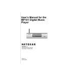
The STM32100E-EVAL demonstration is supplied in one single zip file. The extraction of the
zip file generates one folder, STM32100E-EVAL_FW_VX.Y.Z, which contains the subfolders
shown in Figure 65 and described below.
Figure 65. STM32100E-EVAL demonstration package directory tree
44/49
Doc ID 18064 Rev 1
UM1011
3.1
STM32100E-EVAL demonstration package
Libraries
The Libraries folder contains all the subdirectories and files that make up the core of the
STM32F10xxx Standard Peripheral library VX.Y.Z:
●
●
3.2
CMSIS
–
CM3\CoreSupport: contains the Cortex-M3 files
–
CM3\DeviceSupport\ST\STM32F10x: contains the STM32F10x CMSIS layers
files
STM32F10x_StdPeriph_Driver
–
inc subfolder: contains the Standard Peripheral library header files
–
src subfolder: contains the Standard Peripheral library source files
Project
STM32100E-EVAL
3.3
●
Binary: contains the binary image of the demonstration that can be used to program
the binary image to the internal Flash memory using IAP, plus the Media files required
to run the demonstration (Binary\Media).
●
EWARM: contains preconfigured projects for the EWARM toolchain
●
MDK-ARM: contains preconfigured projects for the MDK-ARM toolchain
●
HiTOP: contains preconfigured projects for the HiTOP toolchain
●
inc subfolder: contains the demonstration header files
●
src subfolder: contains the demonstration source files
●
RIDE: contains preconfigured projects for the RIDE toolchain
●
TrueSTUDIO: contains preconfigured projects for the TrueSTUDIO toolchain
Utilities
STM32100E-EVAL: contains the LCD, and other STM32100E-EVAL board-related drivers.
Doc ID 18064 Rev 1
45/49
STM32100E-EVAL demonstration programming
4
STM32100E-EVAL demonstration programming
4.1
Programming the media files
UM1011
The STM32100E-EVAL board comes with a MicroSD Card memory preprogrammed with
the audio and image resources used by the demonstration. However, you can load your own
image (*.bmp) and audio (*.wav) files in the USER directory, providing that these file formats
are supported by the demonstration. For more details, refer to Section 2.7.4: Wave Player
submenu and Section 2.7.3: Image Viewer submenu.
Figure 66. SD Card directory organization
The default content of the media files (STFILES and USER directories) can be retrieved
from Binary\Media folder. So, if you want to reprogram the MicroSD Card, you can copy the
content of the Binary\Media to your own SD memory.
4.2
Programming the demonstration
You can program the demonstration using three methods:
Using the Bootloader
To program the demonstration binary images into the internal Flash memory, you have to
use the stm32100e_eval_fw_v1.0.0.bin file located under Project\STM32100E-EVAL\Binary
with embedded Bootloader. For more details, please refer to application note AN2606
STM32™ microcontroller system memory boot mode.
Using preconfigured projects
46/49
1.
Select the folder corresponding to your preferred toolchain (MDK-ARM, EWARM,
HiTOP, RIDE or TrueSTUDIO).
2.
Open the STM32100E_EVAL_Demo project and rebuild all sources.
3.
Load the project image through your debugger.
4.
Restart the evaluation board (press B1: reset button).
Doc ID 18064 Rev 1
UM1011
4.2.1
STM32100E-EVAL demonstration programming
Using IAP
To program the demonstration's binary image into the internal Flash memory, you have to
use the stm32100e-eval_fw_Usv1.0.0_offset_0x3000.bin file located under
Project\STM32100E-EVAL\Binary with IAP over USART. For more details, please refer to
IAP application note AN2557 STM32F10x in-application programming using the USART.
Doc ID 18064 Rev 1
47/49
Revision history
5
UM1011
Revision history
Table 4.
48/49
Document revision history
Date
Revision
14-Apr-2011
1
Changes
Initial release.
Doc ID 18064 Rev 1
UM1011
Please Read Carefully:
Information in this document is provided solely in connection with ST products. STMicroelectronics NV and its subsidiaries (“ST”) reserve the
right to make changes, corrections, modifications or improvements, to this document, and the products and services described herein at any
time, without notice.
All ST products are sold pursuant to ST’s terms and conditions of sale.
Purchasers are solely responsible for the choice, selection and use of the ST products and services described herein, and ST assumes no
liability whatsoever relating to the choice, selection or use of the ST products and services described herein.
No license, express or implied, by estoppel or otherwise, to any intellectual property rights is granted under this document. If any part of this
document refers to any third party products or services it shall not be deemed a license grant by ST for the use of such third party products
or services, or any intellectual property contained therein or considered as a warranty covering the use in any manner whatsoever of such
third party products or services or any intellectual property contained therein.
UNLESS OTHERWISE SET FORTH IN ST’S TERMS AND CONDITIONS OF SALE ST DISCLAIMS ANY EXPRESS OR IMPLIED
WARRANTY WITH RESPECT TO THE USE AND/OR SALE OF ST PRODUCTS INCLUDING WITHOUT LIMITATION IMPLIED
WARRANTIES OF MERCHANTABILITY, FITNESS FOR A PARTICULAR PURPOSE (AND THEIR EQUIVALENTS UNDER THE LAWS
OF ANY JURISDICTION), OR INFRINGEMENT OF ANY PATENT, COPYRIGHT OR OTHER INTELLECTUAL PROPERTY RIGHT.
UNLESS EXPRESSLY APPROVED IN WRITING BY AN AUTHORIZED ST REPRESENTATIVE, ST PRODUCTS ARE NOT
RECOMMENDED, AUTHORIZED OR WARRANTED FOR USE IN MILITARY, AIR CRAFT, SPACE, LIFE SAVING, OR LIFE SUSTAINING
APPLICATIONS, NOR IN PRODUCTS OR SYSTEMS WHERE FAILURE OR MALFUNCTION MAY RESULT IN PERSONAL INJURY,
DEATH, OR SEVERE PROPERTY OR ENVIRONMENTAL DAMAGE. ST PRODUCTS WHICH ARE NOT SPECIFIED AS "AUTOMOTIVE
GRADE" MAY ONLY BE USED IN AUTOMOTIVE APPLICATIONS AT USER’S OWN RISK.
Resale of ST products with provisions different from the statements and/or technical features set forth in this document shall immediately void
any warranty granted by ST for the ST product or service described herein and shall not create or extend in any manner whatsoever, any
liability of ST.
ST and the ST logo are trademarks or registered trademarks of ST in various countries.
Information in this document supersedes and replaces all information previously supplied.
The ST logo is a registered trademark of STMicroelectronics. All other names are the property of their respective owners.
© 2011 STMicroelectronics - All rights reserved
STMicroelectronics group of companies
Australia - Belgium - Brazil - Canada - China - Czech Republic - Finland - France - Germany - Hong Kong - India - Israel - Italy - Japan Malaysia - Malta - Morocco - Philippines - Singapore - Spain - Sweden - Switzerland - United Kingdom - United States of America
www.st.com
Doc ID 18064 Rev 1
49/49