1
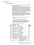
RespiPatient® User’s Manual © IngMar Medical, Ltd. 2014 - 2015 This page intentionally left blank RespiPatient User’s Manual Legal Information Product Warranty Educational tools and test instruments manufactured or distributed by IngMar Medical Ltd. are fully warranted, covering materials and workmanship for a period of one year from the date of shipment, except for products with stated warranties other than one year. IngMar Medical reserves the right to perform warranty service(s) at its factory, at an authorized repair station, or at the customer's installation. IngMar Medical's obligations under this warranty are limited to repairs, or at IngMar Medical's option, replacement of any defective parts of our equipment, except fuses and batteries, without charge, if said defects occur during normal service. RespiPatient® User’s Manual – 80 31 805 – Rev. 1, © IngMar Medical, Ltd. 2014-2015 Claims for damages during shipment must be filed promptly with the transportation company. All correspondence concerning the equipment must specify both the model name and number, and the serial number as it appears on the equipment. Improper use, mishandling, tampering with, or operation of the equipment without following specific operating instructions will void this warranty and release IngMar Medical from any further warranty obligations. The above is the sole warranty provided by IngMar Medical, Ltd. No other warranty, expressed or implied, is intended. Representatives of IngMar Medical are not authorized to modify the terms of this warranty. For factory repair service, call: Toll free: 1-800-583-9910 International: (412) 441-8228 Facsimile: (412) 441-8404 or contact us via e-mail at: [email protected] Our shipping address: IngMar Medical, Ltd. 5940 Baum Blvd Pittsburgh, PA 15206 USA Limitation of Liability IngMar Medical Ltd.'s liability, whether arising out of or related to manufacture and sale of the goods, their installation, demonstration, sales representation, use, performance, or otherwise, including any liability based upon above defined product warranty, is subject to and limited to the exclusive terms and conditions as set forth, whether based upon breach of warranty or any other cause of action whatsoever, regardless of any fault attributable to IngMar Medical, and regardless of the form of action (including, without limitation, breach of warranty, negligence, strict liability, or otherwise). THE STATED EXPRESSED WARRANTIES ARE IN LIEU OF ALL OTHER WARRANTIES, EXPRESSED OR IMPLIED, INCLUDING, WITHOUT LIMITATION, WARRANTIES OF MERCHANTABILITY, FITNESS FOR ANY PARTICULAR PURPOSE, OR NONINFRINGEMENT. IngMar Medical, Ltd. shall not be liable for, nor shall buyer be entitled to recover, any special incidental or consequential damages or for any liability incurred by buyer to any third party in any way arising out of or relating to the goods. Trademarks RespiPaitent is a registered trademark of IngMar Medical, Ltd. ® All other trademarks or registered trademarks are property of their respective owners. Copyright © 2014 - 2015, IngMar Medical, Ltd. No parts of this document may be reproduced, stored in a retrieval system, translated, transcribed, or transmitted, in any form, or by any means, without identifying its authorship as IngMar Medical, Ltd. Please note that a valid return merchandise authorization (RMA) number is always required before sending in any products for repair, calibrations, or updates. 3 This page intentionally left blank RespiPatient User’s Manual Contents 1 Operator Safety ..............................................6 5 Maintenance ................................................. 17 1.1 Warnings and Caution Statements ................6 5.1 Service and Calibration Intervals ................ 17 1.2 Intended Use ................................................6 5.2 Cleaning and Storage ................................. 17 1.3 General Precautions .....................................6 5.3 Replacing Tissue Inserts ............................. 17 2 Introduction ...................................................7 5.3.1. Replacing Needle Decompression Inserts .............................................................. 17 2.1 Overview .....................................................7 2.2 Available Options ........................................7 2.3 Features .......................................................7 2.3.1. RespiPatient Features ................................7 2.3.2. Lung Features ...........................................7 3 RespiPatient Setup ..........................................8 3.1 Quick Setup Diagram ...................................8 3.2 Step-by-Step RespiPatient Setup ...................9 3.2.1. Manikin to Interface Box ..........................9 3.2.2. Manikin to ASL 5000 Connections .........10 RespiPatient® User’s Manual – 80 31 805 – Rev. 1, © IngMar Medical, Ltd. 2014-2015 3.2.3. Tongue Inflation Tubing .........................11 3.2.4. Bypass Mode ..........................................11 4 Operation .....................................................12 4.1 How It Works .............................................12 4.2 Preparing RespiPatient for Use ...................12 4.3 Starting Up .................................................12 4.4 Operating RespiPatient ...............................12 4.4.1. Chest Rise ...............................................12 5.3.2. Replacing Chest Drain Inserts ................. 18 5.3.3. Replacing Neck Skin and Larynx Membrane Inserts ................................... 18 6 Specifications ............................................... 20 6.1 Electrical Specifications .............................. 20 6.1.1. Supply Voltage ....................................... 20 6.2 Physical Specifications ............................... 20 6.2.1. RespiPatient............................................ 20 6.2.2. RespiPatient Interface Box ...................... 20 6.2.3. Hard-Sided Transport Case ..................... 20 6.3 Ancillary Materials Specifications ............... 20 6.4 Environmental Specifications ..................... 20 6.4.1. Storage ................................................... 20 6.4.2. Operation ............................................... 20 7 Support Resources ........................................ 21 8 Consumables Replacement ........................... 22 9 Index ............................................................ 23 4.4.2. Tension Pneumothorax, Venous Engorgement, Tracheal Deviation ...........13 4.4.3. Swollen Tongue ......................................14 4.4.4. Breakaway Teeth ....................................14 4.4.5. Intubation ...............................................14 4.4.6. Chest Drain ............................................14 4.4.7. Cardiopulmonary Resuscitation ..............14 4.4.8. Carbon Dioxide Infusion ........................14 4.4.9. Cricothyroidotomy and Tracheostomy ....15 5 RespiPatient User’s Manual 1 Operator Safety To insure correct and effective use of RespiPatient, read and follow all instructions, WARNINGS, and CAUTION statements in this manual. If the product is not used as instructed, the safety protection provided may be impaired. 1.1 Warnings and Caution Statements WARNING ! Always follow ventilator manufacturers’ instructions and recommendations regarding use and operation of ventilator equipment in conjunction with RespiPatient. IngMar Medical, Ltd. does not recommend any specific ventilator and no portion of these instructions shall be construed as doing so. WARNING ! Indicates a potentially harmful condition that can lead to personal injury. CAUTION ! Indicates a condition that may lead to equipment damage or malfunction. NOTE: Indicates points of particular interest or emphasis for more efficient or convenient operation. Intended Use IngMar Medical’s RespiPatient is a specialized respiratory manikin with an anatomically correct airway and chest structure. RespiPatient is intended to be used for demonstrations, in-services, and training respiratory staff in skills such as resuscitation and comprehensive ventilator management. RespiPatient is part of IngMar Medical’s RespiSim® system, a platform for respiratory care instruction with time saving features for instructors to provide higher quality and more consistent training content, higher skill levels for students, and, ultimately, better patient care. 6 RespiPatient is not intended for the purpose of assisting in clinical decisions regarding actual patients. 1.3 General Precautions CAUTION ! Electrical Supply: Connect device only to a properly grounded wall outlet providing 100 - 240 V AC, 50 - 60 Hz. CAUTION ! Do not operate the RespiPatient Interface box when it is wet due to spills or condensation. Never sterilize or immerse the device in liquids. CAUTION ! Do not operate the RespiPatient Interface box if it appears to have been, opened, dropped, or damaged. RespiPatient® User’s Manual – 80 31 805 – Rev. 1, © IngMar Medical, Ltd. 2014- 2015 1.2 WARNING ! - NOT FOR CLINICAL USE - RespiPatient User’s Manual 2 Introduction 2.1 Overview RespiPatient is a specialized respiratory featurecentered torso manikin with bilateral chest rise and intubation-grade normal and difficult airway. In addition, it allows for training of needle decompression (pneumothorax), chest tube insertion, as well as cricothyrotomy and tracheotomy procedures. RespiPatient enables you to train the full range of airway management and CPR skills with anatomically correct airway, rib cage, three-layered tissue, “real feel” skin covering, and realistic chest rise. Replaceable tissue sets allow each learner a life-like and unique experience for training. RespiPatient® User’s Manual – 80 31 805 – Rev. 1, © IngMar Medical, Ltd. 2014-2015 RespiPatient consists of a torso manikin that connects to the RespiPatient Interface box. The RespiPatient Interface box drives the features of the RespiPatient manikin using IngMar Medical’s ASL 5000 Breathing Simulator to provide high-fidelity, spontaneously breathing lungs. 2.2 Available Options Options that can be added to the base system include: • Mobile Cart: Integrates ASL 5000 and RespiPatient for in-situ simulation training, wherever a ventilator is located. • RespiScope™ Advanced Auscultation: Enables realistic practice and mastery of auscultation skills critical for diagnosis. Lung, heart, and bowel sounds are provided. Consult the RespiScope User’s Manual for operation of RespiScope and the RespiScope software. 2.3 Features 2.3.1. RespiPatient Features • Tension pneumothorax § Identification of tracheal deviation and jugular vein distension § Right or left tension pneumothorax § Needle decompression (with familiar “hiss” sound) • Chest tube insertion § Recognition of correct position in the 5th, 6th, and 7th intercostal space § Blunt dissection through chest wall • Surgical skills § Cricothyrotomy § Tracheotomy • CO2 production for capnography • Torso manikin easier to move and store than full body manikin NOTE: Mouth-to-mouth resuscitation is NOT recommended on RespiPatient as the airway is not designed to handle hygienic precautions for use by multiple students. 2.3.2. Lung Features At the core of RespiPatient is the spontaneously breathing ASL 5000 Breathing Simulator— the world’s most sophisticated breathing simulator. • Spontaneous breathing controls: Examine patient-ventilator interaction with a spontaneously breathing patient including coughs, apnea, active exhalation, playback of actual patient recordings – even snoring! • Disease state modeling: Quickly access patient models as a basis for your particular situation or create your own unique scenarios. You can always change patient parameters “on the fly” when needed. • Reproducible patients: Ensure consistent instruction and skills assessment. For further information on the operation and use of the ASL 5000 Breathing Simulator, please refer to the ASL 5000 User’s Manual. • Cardiopulmonary resuscitation: life-like recoil during chest compressions • Intubation – orotracheal, nasotracheal, combitube, LMA placement, difficult airway (tongue edema) • Bag-valve-mask ventilation techniques • 7 RespiPatient User’s Manual 3 RespiPatient Setup 3.1 Quick Setup Diagram 8 RespiPatient Quick Setup Diagram RespiPatient® User’s Manual – 80 31 805 – Rev. 1, © IngMar Medical, Ltd. 2014- 2015 Figure 3-1 RespiPatient User’s Manual 3.2 Step-by-Step RespiPatient Setup To connect RespiPatient, the RespiPatient Interface box, and the ASL 5000 Breathing Simulator, start by placing RespiPatient, the RespiPatient Interface box and the ASL 5000 on a table in close proximity to each other. Stack the ASL 5000 on top of the RespiPatient Interface box by placing the ASL 5000 feet into the orange cups on top of the Interface box. Figure 3-4 Interface Box- Right Lung Figure 3-5 RespiPatient - Right Lung 3.2.1. Manikin to Interface Box Lung Connections Left Lung Connection Insert the female end of a lung tube into the Interface box Lung port labeled “L.” Insert the male end of the same lung tube into the RespiPatient Left Lung port. RespiPatient® User’s Manual – 80 31 805 – Rev. 1, © IngMar Medical, Ltd. 2014-2015 Pneumothorax Connection Interface Box Pneumo Connection Insert the single-connector end of the Pneumothorax tubing into the Interface box port labeled “Pneumo.” Figure 3-2 Interface Box - Left Lung Figure 3-6 Figure 3-3 Interface Box Pneumo Connection RespiPatient Left Lung Connection Right Lung Connection Insert the male end of a lung tube into the Interface box Lung port labeled “R.” Insert the female end of the same lung tube into the RespiPatient Right Lung port. 9 RespiPatient User’s Manual RespiPatient Left Pneumo Connection Insert the clear tubing end into the port labeled “Tension Pneumo Left.” Then turn the connector slightly to the right (clockwise) to snap it into place. Figure 3-9 RespiPatient Trachea Connection Figure 3-7 Left Pneumo Connection ASL 5000 Trachea Connection Insert the other end of the trachea tube into the front panel of the ASL 5000 as shown. RespiPatient Right Pneumo Connection Insert the black tubing into the port labeled “Tension Pneumo Right.” Then turn the connector slightly to the right (clockwise) to snap it into place. Power Connections Figure 3-8 Right Pneumo Connection 3.2.2. Manikin to ASL 5000 Connections RespiPatient Interface box to ASL 5000 Short Power Cord Connection Connect one end of the 6” Power Cord into RespiPatient Interface box power socket as shown and the other end into the ASL 5000 power socket. Trachea Connections RespiPatient Trachea Connections Insert the elbow end of the trachea tube into the port labeled “ASL 5000/Trachea” as shown. Figure 3-11 10 Interface box to ASL 5000 Short Power Cord Connection RespiPatient® User’s Manual – 80 31 805 – Rev. 1, © IngMar Medical, Ltd. 2014- 2015 Figure 3-10 ASL 5000 Trachea Connection RespiPatient User’s Manual RespiPatient Interface box Power Connection Connect the power cord to the RespiPatient Interface box as shown. Insert the other end into an AC power source. 3.2.3. Tongue Inflation Tubing Insert the connector end of the tongue inflation tube into the manikin in the black connector labeled “Tongue Inflation” as shown. Then turn the connector slightly to the right (clockwise) to engage. Figure 3-15 RespiPatient Tongue Connection 3.2.4. Bypass Mode Figure 3-12 Interface Box Power Connection To operate RespiPatient in stand-alone mode without the ASL 5000, connect the Bypass Tubing as shown in Figure 3-16. RespiPatient® User’s Manual – 80 31 805 – Rev. 1, © IngMar Medical, Ltd. 2014-2015 Interconnect Cable Connect one end of the interconnect cable into the back of the RespiPatient Interface box and the other end of the cable into the back of the ASL 5000 as shown. Figure 3-16 Figure 3-13 Interface Box Figure 3-14 ASL Interconnect Cable Connection on ASL 5000 Bypass Mode 11 RespiPatient User’s Manual 4 Operation 4.1 How It Works The ASL 5000 Breathing Simulator sends signals to the RespiPatient Interface box driving RespiPatient’s chest rise, venous engorgement, tracheal deviation, and tension pneumothorax. The ASL 5000 serves as the simulated lungs for RespiPatient using the ASL 5000 trachea port connection to the base of the manikin, through the manikin’s trachea, and the manikin’s mouth. This means that the air flowing in and out of the chest rise bags in the manikin are completely separate from the “breathing” air flowing through the trachea. 4.2 Preparing RespiPatient for Use RespiPatient. Note that the light in the switch will illuminate indicating that power is on you will not hear any sounds. • Wait for the red indicator light on the front of the ASL 5000 to turn off. • Start the ASL 5000 Software as directed in the ASL 5000 User’s Manual (clicking on the ASL 3.5 icon on the computer’s desktop). • Connect to the ASL 5000 simulator based on the user-defined connection type (Ethernet or USB/Serial). 4.4 Operating RespiPatient 4.4.1. Chest Rise Activate RespiPatient’s chest rise by running a simulation from the ASL 5000 or RespiSim software. Once a simulation is running, the "Pump" LED on the front of the RespiPatient Interface box illuminates and the manikin’s chest rises and falls. 4.3 Starting Up Figure 4-1 Pump On/Off LED NOTE: Because the ASL 5000 controls the Interface box, first connect the RespiPatient Interface box and then follow these steps in the order listed to run the full system properly. For further information on the ASL 5000 operation in the steps below, consult the ASL 5000 User’s Manual. Resistance, Compliance, and Muscle Effort (if applied) in the patient model used in the simulation directly affects the visual chest rise. The amount of chest rise seen is directly related to the volume waveform shown in the ASL software’s Central Run-Time window or Run Time Home window. To start operation of RespiPatient with the ASL 5000, follow these steps: For example: • Greater effort with high compliance and low resistance will result in a larger chest rise. • Smaller effort with lower compliance and higher resistance will result in a smaller chest rise. • For a sedated patient receiving controlled breaths from an ICU ventilator, chest rise is, in the same way, a function of breath size. • Use the green switch on the back of the ASL 5000 to turn on power to the ASL 5000. The small blue LED inside the IngMar Medical logo on the front panel will indicate that power is on • Use the green switch on the back of the RespiPatient Interface box to turn on power to 12 RespiPatient® User’s Manual – 80 31 805 – Rev. 1, © IngMar Medical, Ltd. 2014- 2015 • Remove RespiPatient from the black carrying case. • Ensure that all components are present and the tissue sets are connected and secure. • Place RespiPatient on its back. • Please ensure all airway devices are prepared to the manufacturer’s recommendations and instructions. Before insertion of any device, generous amounts of lubricant should be used to cover the surfaces in contact with the airway. RespiPatient User’s Manual The system also has the ability to provide bilateral (individual, left/right) chest rise if using a duallung model with varying left and right lung compliance and resistance settings. Please see the ASL 5000 Breathing Simulator User’s Guide for information on building a lung model. 4.4.2. Tension Pneumothorax, Venous Engorgement, Tracheal Deviation RespiPatient provides the ability to simulate a combination tension pneumothorax, venous engorgement, and tracheal deviation. These inserts are located in the second intercostal space at the mid-clavicular line. RespiPatient® User’s Manual – 80 31 805 – Rev. 1, © IngMar Medical, Ltd. 2014-2015 Figure 4-2 Figure 4-3 Manual Interface Box Pneumo Activation • The second method is to activate the pneumothorax through the RespiSim software. Refer to the RespiSim Manual for instructions on running a simulation with a tension pneumothorax, venous engorgement, and tracheal deviation. Needle Decompression Each insert is composed of durable tissue capable of handling 30+ needle punctures. The venous engorgement and tracheal deviation are internal to the manikin and connected to the same air line that fills the needle decompression sites. When the user initiates the inflation of these regions, the following changes occur: • The needle decompression insert inflates. • A pillow inside the manikin inflates causing the trachea to shift (tracheal deviation). • A pillow in the neck inflates, creating a bulge in the neck (venous engorgement). Figure 4-4 RespiSim Pneumo Activation When the pneumo button (real or virtual) is engaged, the three cavities will inflate to a pressure of approximately 70 mbar. Sensors in the RespiPatient Interface box prevent over-inflation of the three cavities. If an unintentional inflation occurs, the user can release the air within the cavities by removing the needle decompression insert and reinserting the air tube. Piercing the needle decompression site will result in a “hissing” sound and will deflate all pillows to “stabilize” the patient. There are two methods available for the user to force these cavities to inflate: • The first method is to manually press the Pneumo L or R buttons on the RespiPatient Interface box. Figure 4-5 Removing the Needle Decompression Insert 13 RespiPatient User’s Manual Figure 4-6 Remove and Reinsert Air Tube Figure 4-9 Breakaway Teeth 4.4.3. Swollen Tongue 4.4.5. Intubation RespiPatient’s tongue can be inflated to simulate a swollen tongue. This creates increased resistance in the airway as well as making it difficult to intubate the manikin. To initiate the tongue inflation, shut the relief valve (turn clockwise) on the connected tongue inflation bulb and squeeze the bulb enough to see the jaw adjust. To relieve pressure in the tongue, open the valve (counterclockwise) on the tongue bulb. RespiPatient provides the most anatomically correct airway in the industry. Intubation training can be performed through the mouth or either nostril. See the Ancillary Materials specifications at the end of this manual for recommended sizes. RespiPatient can be used to train on any ventilator. The connection is made either with any invasive airway management device or with a mask, for non-invasive ventilation, just like with a real patient. 4.4.6. Chest Drain Inflatable Tongue 4.4.7. Cardiopulmonary Resuscitation Figure 4-8 Tongue Bulb Relief Valve The anatomically correct chest structure allows for easy identification of all anatomical landmarks. RespiPatient can be adjusted for headtilt, chin lift, and jaw thrust in order to prepare the patient for proper resuscitation training and simulation. The chest cavity has realistic recoil during compressions as well. 4.4.4. Breakaway Teeth 4.4.8. Carbon Dioxide Infusion The breakaway teeth provide a good representation of the fragility of human teeth. RespiPatient’s teeth attach to the gums with a small plastic tether. If the teeth break off during an unskilled attempt at intubation, they remain tethered to the upper gums. Reset them by pressing them back into position in the upper gums. The RespiPatient Interface box provides the ability to control carbon dioxide flow into the patient airstream. The system supports a range of 0 to 600 mL/min. Control the flow from the ASL 5000 software on the Instructor Dashboard. Access the Instructor Dashboard from the RespiSim Debrief window. Consult the RespiSim Manual for more information. 14 RespiPatient® User’s Manual – 80 31 805 – Rev. 1, © IngMar Medical, Ltd. 2014- 2015 Figure 4-7 Each side of RespiPatient incorporates a removable chest drain cavity, which can be filled with liquids to represent a hemothorax or pleural effusion. Incisions can be made through the fifth, sixth, and seventh intercostal spaces. The cavity insert is a consumable part that will require replacement after incisions are made. RespiPatient User’s Manual RespiPatient includes two connectors for input and output of the CO2 stream. The CO2 source is not included and must be limited to 25 PSI (175 KPa) for proper operation. CO2 pressures exceeding this limit may result in inaccurate flows into the airstream. The green LED indicates when the flow has reached user input settings as follows: • When the LED is a solid green: The CO2 flow is within the set value range • When the LED is toggling on and off: Either the CO2 flow has not yet reached the set value or the external CO2 supply is too low and the CO2 source should be replaced. RespiPatient® User’s Manual – 80 31 805 – Rev. 1, © IngMar Medical, Ltd. 2014-2015 To adjust the CO2 flow from the ASL 5000 software, access the RespiSim software, and load a preconfigured module. From the Instructor Dashboard, adjust the “CO2 Settings [mL/min] (RespiPatient)” slide-bar, or place a desired value into the input box. Please note that setting increments are in steps of 10 mL/min. Figure 4-10 Interface Box Side Panel Figure 4-11 CO2 Output Connector Figure 4-14 CO2 Settings in RespiSim 4.4.9. Cricothyroidotomy and Tracheostomy Figure 4-12 CO2 Input Connector The push button switch on the side of the RespiPatient Interface box drives the CO2 flow. Figure 4-13 RespiPatient provides allows for performance of needle and surgical cricothyroidotomy and percutaneous tracheostomy. RespiPatient has anatomically accurate simulated cricoid, laryngeal cartilages, and palpable tracheal rings, allowing easier identification of the correct landmarks to begin needle and surgical cricothyroidotomy and percutaneous tracheostomy procedures. CO2 On/Off Switch and LED 15 RespiPatient User’s Manual The system also includes replacement neck skin and larynx membrane inserts. Membrane inserts provide life-like resistance for the cricothyroid membrane and tracheal cartilages. When performing these procedures, make sure to reseal the airway with the included Airway Sealing Tape before the next use. Figure 4-15 Cricothyroid Membrane & Tracheal Cartilages RespiPatient® User’s Manual – 80 31 805 – Rev. 1, © IngMar Medical, Ltd. 2014- 2015 16 RespiPatient User’s Manual 5 Maintenance 5.1 Service and Calibration Intervals There are no calibration or servicing requirements for RespiPatient or RespiPatient Interface box. For details about service needs or extended warranty plans, please contact IngMar Medical Customer Care at: 1-800-683-9910, or +1 (412) 441-8228 ext. 107 or e-mail to [email protected]. 5.2 Cleaning and Storage RespiPatient® User’s Manual – 80 31 805 – Rev. 1, © IngMar Medical, Ltd. 2014-2015 • Store RespiPatient in clean, dry conditions away from heat and direct sunlight; avoid contact with metals, solvents, oils or greases, and strong detergents. • Please ensure that the airway is cleaned after use as necessary. When appropriate, wash the RespiPatient airway with warm soapy water until all visible foreign matter and residue is removed. CAUTION ! Prior to cleaning the RespiPatient Airway, be sure that the trachea line to the ASL 5000 is disconnected to prevent introducing liquids into the ASL 5000. • When cleaning the airway, use a small soft bristle brush (approximately ½ inch or 12.5mm in diameter). Gently insert the brush through the airway, taking care not to damage the material. Extra care must be taken when cleaning around the vocal cords. • Carefully inspect the device to ensure that all visible foreign matter has been removed. • The head and neck skin of RespiPatient is made from durable and very elastic polymer material. It can be cleaned using a lightly soapy, damp cloth. Please do not use detergents or cleaning agents on the skin material. • During chest drain procedures with the addition of fluid (blood-like fluid) in the cavity, the model may experience some residual deposits. These can be cleaned using warm soapy water and dried using a cloth. CAUTION ! Please DO NOT USE any of the following when cleaning RespiPatient: • Germicides, disinfectants, or chemical agents such as glutaraldehyde (e.g. Cidex®). • Ethylene oxide, phenol-based cleaners, or iodine-containing cleaners. Such substances are absorbed by RespiPatient materials, resulting in exposing the user to unnecessary risk and possible deterioration of the device. Do not use a device that has been cleaned with any of these substances. 5.3 Replacing Tissue Inserts The needle decompression and chest drain inserts are designed for multiple uses. RespiPatient comes ready for use with needle decompression, chest drain, and neck skin inserts in place. After exhausting the use of the inserts, they should be replaced as described below. To obtain replacement tissue inserts, refer to Section 8 – Consumables. 5.3.1. Replacing Needle Decompression Inserts Failure of the needle decompression insert will be evident when the air tightness of the manikin’s decompression insert begins to decrease and there is a lack of “hiss” when performing the needle decompression maneuver. The insert may work successfully for more than 30 needle incisions. Conduct regular inspections to ensure optimal performance. To replace the needle decompression inserts: • Remove the outer chest skin to gain access to the needle decompression insert site. • Gently remove the insert away from the slotted rib structure. This will reveal the internal tubing. 17 RespiPatient User’s Manual • Slowly separate the tubing from the needle decompression insert to free the insert. • Dispose of the insert safely. • Inserts are labeled L for left and R for right for easy identification. • Insert the tubing end into the hole. Ensure the tubing end is inserted all the way to the last barb. • Reinsert the tissue set into the slotted rib structure. A small amount of lubrication can be added to reduce the friction upon entry. • Push the tubing inside the chest cavity. • Re-assemble the chest skin and tuck back into position. • Make sure the tissue set is flush with the outer skin and is positioned correctly in relation to the ribs. • Take time to ensure the tissue inserts are inserted correctly as a faulty connection will affect the operation of the feature. 5.3.2. Replacing Chest Drain Inserts There are two options for the chest drain replacement tissues: economy or premium. The premium product provides a three-layered tissue representing; skin, fat tissue and muscle. Each of these layers are pigmented to the applicable color anatomically and provide a realistic feel and touch. The insert position, which is between the ribs, allows for realistic palpations of the correct intercostal landmarks, chest tube insertion can be carried out in the 5th / 6th / 7th intercostal space. The inserts provide the option of inserting fluid (not provided) to the cavity, simulating the experience of breaking into the pleural cavity with a gush of fluid released. (We recommend using water to avoid staining RespiPatient with blood-like substances). The chest drain insert is designed so that the tube can be sutured in place. Each intercostal landmark can be used once or twice depending on the size of the incision performed. 18 5.3.3. Replacing Neck Skin and Larynx Membrane Inserts A new larynx membrane insert can be used for each trainee to provide a unique experience. The piece can be easily removed and replaced. • Ensure that the larynx is pushed down as far as it will go against the sternum wall, so it will be in the right position. • When practicing airway management procedures, cut a piece of sealing tape approximately 2 – 2.5 inches (5 - 6 cm) and attach it over the Crico and Trach hole in the airway. For proper adhesion, make sure the airway is clean and dry before attaching the tape for proper adhesion. • Lubricate the internal airway and the nasal passage with the silicone lubricant provided. • Ensure all airway devices are prepared to the manufacturer’s recommendations and instructions. RespiPatient® User’s Manual – 80 31 805 – Rev. 1, © IngMar Medical, Ltd. 2014- 2015 RespiPatient comes equipped with the economy option, which consists of one solid layer of special silicone blend. This is the more economical option for training e.g. for use in ATLS courses. To replace the chest drain inserts: • Tuck the chest skin out from the insert and remove from the ribs. If liquid has been introduced, please take extra care during removal. • Dispose of the tissue insert safely • If liquid has been used to illustrate hemothorax, dry the internal structure to ensure there have been no leakages. • Chest drain inserts are labeled L for left and R for right for easy identification. • Align the set with the slotted rib compartments. • If using liquid, remove the red sealing cap and insert the desired fluid (we recommend water to avoid staining). • Fill the cavity to the desired level and tighten the cap. • A small amount of lubrication can be added to reduce the friction upon entry. The insert should fit into position with little force. • Ensure again that the insert is parallel and aligned with the outer skin. Run your finger around the edge of the insert for correct alignment. RespiPatient User’s Manual RespiPatient® User’s Manual – 80 31 805 – Rev. 1, © IngMar Medical, Ltd. 2014-2015 • Before insertion of the airway device, generous amounts of lubricant should be used to cover the surfaces in contact with the airway, the cricothyroid membrane, and the tracheal rings. • To ensure full functionality, securely attach pieces using the hook-and-loop type fasteners. 19 RespiPatient User’s Manual 6 Specifications 6.1 Electrical Specifications 6.4 Environmental Specifications 6.4.1. Storage Temperature: 6.1.1. Supply Voltage -10 ºC to 50 ºC (allow device to reach approximate room temperature before use) 10 to 95%, noncondensing Input/Output: 100 to 240 V AC Humidity: 6.2 6.4.2. Operation Physical Specifications 6.2.1. RespiPatient Dimensions (lying on tabletop): 27.5" X 18.25" X 9.5" (69.85 cm X 46.36 cm X 24 cm) Weight: Approx. 23 lbs (10.4 kg) Temperature: Humidity: +10 ºC to 40 ºC 10 to 95%, noncondensing NOTE: Specifications are subject to change without notice. 6.2.2. RespiPatient Interface Box Dimensions: 17.25" X 8.625" X 5.125" (43.815 cm X 21.9 cm X 13 cm) Weight: Approx. 24 lbs (10.9 kg) 6.2.3. Hard-Sided Transport Case Weight: Approx. 110 lbs (49.9 kg) (Complete system in transport case) 6.3 Ancillary Materials Specifications Obtain the ancillary materials listed below using the stated parameters for selecting the correct sizes: Nasal Intubation: 6.0 mm ID Oral Intubation: 8.0 mm ID LMA laryngeal masks: Size 3-5 Similar respective sizes for other supraglottic devices 20 RespiPatient® User’s Manual – 80 31 805 – Rev. 1, © IngMar Medical, Ltd. 2014- 2015 External Dimensions: 37" X 27.2" X 14.4" (94 cm X 69 cm X 36.6 cm) RespiPatient User’s Manual 7 Support Resources IngMar Medical is dedicated to customer support. We encourage you to visit our website at www.ingmarmed.com for support options. While the primary source of user information is this User’s Manual, there are a number of other ways to receive support. • Updated editions of this User’s Manual can be downloaded from the IngMar Medical website. • Answers to Frequently Asked Questions (FAQs) are accessible via our website. • We provide in-depth, hands-on small group customer-site training. RespiPatient® User’s Manual – 80 31 805 – Rev. 1, © IngMar Medical, Ltd. 2014-2015 Please contact Customer Care at 1-800-583-9910, ext. 107, about purchasing additional support plans or training. Email us at [email protected]. Or contact us from the Contact Us page of our website, www.ingmarmed.com. 21 RespiPatient User’s Manual 8 Consumables Replacement Consumable items are available for RespiPatient including: • Lubrication – Part # 15 30 744 • Airway Sealing Tape – Part # 31 10 780 • Overlay Neck Skin Cover (pack of 5) – Part # 31 10 781 • Replaceable Combo Larynx – Part # 31 10 782 • Subcutaneous Fat Tissue (pack of 5) – Part # 31 10 783 • Chest Drain Inserts Three Layer (set) – Part # 31 10 784 • Chest Drain Inserts One Layer (set) – Part # 31 10 785 • Larynx Membrane Inserts (pack of 50) – Part # 31 10 786 Please contact Customer Care at 1-800-583-9910, ext. 107 if you are interested in purchasing consumable items. Email us at [email protected]. Or contact us from the Contact Us page of our website, www.ingmarmed.com. 22 RespiPatient® User’s Manual – 80 31 805 – Rev. 1, © IngMar Medical, Ltd. 2014- 2015 Alternatively, contact TruCorp for consumable items by visiting http://www.trucorp.com/consumables/. RespiPatient User’s Manual RespiPatient® User’s Manual – 80 31 805 – Rev. 1, © IngMar Medical, Ltd. 2014-2015 9 Index Airway Management .......................................... 7 Ancillary Materials Specifications ..................... 20 ASL 5000 Trachea Connection ......................... 10 Breakaway Teeth .............................................. 14 Bypass Mode .................................................... 11 Capnography ...................................................... 7 Carbon Dioxide Infusion .................................. 14 Cardiopulmonary Resuscitation ........................ 14 Chest Drain ................................................ 14, 22 Chest Drain Inserts ........................................... 18 Chest Rise......................................................... 12 Cleaning and Storage........................................ 17 Consumables Replacement ............................... 22 Cricothyroid Membrane ................................... 16 Cricothyroidotomy ........................................... 15 Electrical Specifications .................................... 20 Environmental Specifications ............................ 20 Features .............................................................. 7 General Precautions ........................................... 6 Hard-Sided Transport Case ............................... 20 How It Works ................................................... 12 Intended Use ...................................................... 6 Interconnect Cable ........................................... 11 Interface Box Pneumo Connection ..................... 9 Intubation ............................................... 7, 14, 20 Laryngeal Cartilages ......................................... 15 Left Lung Connection ......................................... 9 Limitation of Liability.......................................... 3 Lung Features ..................................................... 7 Lungs Connections ............................................. 9 Manikin To ASL 5000 Connections .................. 10 Manikin To Interface Box ................................... 9 Mouth-To-Mouth Resuscitation .......................... 7 Needle Decompression ................................ 7, 13 Needle Decompression Inserts ......................... 17 Operator Safety ................................................... 6 Options............................................................... 7 Physical Specifications ...................................... 20 Pneumothorax .................................................... 9 Power Connections ........................................... 10 Preparing Respipatient For Use ......................... 12 Product Warranty................................................ 3 Quick Setup Diagram ......................................... 8 Replacing Chest Drain Inserts ........................... 18 Replacing Neck Skin and Larynx Membrane Inserts............................................................ 18 Replacing Needle Decompression Inserts ......... 17 Replacing Tissue Inserts .................................... 17 Respipatient Features .......................................... 7 Respipatient Interface Box Power Connection ... 11 Respipatient Left Pneumo Connection................. 9 Respipatient Right Pneumo Connection ............ 10 Respipatient Trachea Connection...................... 10 Respiscope.......................................................... 7 Right Lung Connection ....................................... 9 Service and Calibration Intervals ....................... 17 Specifications.................................................... 20 Step-By-Step Respipatient Setup .......................... 9 Support Resources ............................................ 21 Swollen Tongue ................................................ 14 Tension Pneumothorax ..................................... 13 Tissue Inserts..................................................... 17 Tongue ....................................................... 11, 14 Tongue Inflation Tubing .................................... 11 Trachea Connections ........................................ 10 Tracheal Deviation ................................. 7, 12, 13 Tracheal Rings .................................................. 15 Tracheostomy ................................................... 15 Venous Engorgement .................................. 12, 13 Warning and Caution Statements ........................ 6 23