1
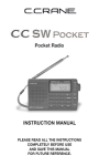
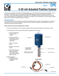
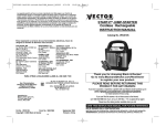
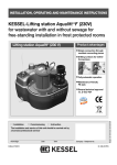
X143HP Hydro
Powered Generator
Installation • Operation • Maintenance
Power Generator Unit
X143HP
CLA-VAL
DC Charge Controller Display
Diversion Load
Battery Housing
X143HP Installation, Operation and Maintenance Manual
Table of Contents
Page #
Introduction
1
Section 1: System Components and How They Work
1.1
1.2
Section 2: Installation of Components
2.1
2.2
2.3
2.4
2.5
2.6
2.7
2.8
2.9
Mounting the Power Generation Unit
Connecting the Power Generation Unit to the Water Supply
Mounting and Wiring the Control Cabinet
Mounting and Wiring the Diversion Load
Setting Up a Battery Bank and Manual Disconnect
Connecting User Devices
Connecting the X143HP Power Unit to the Control Cabinet
Adding Customer Devices
Wiring Schematic
Section 3: Control Cabinet Setting
3.1
3.2
3.3
3.4
Starting Operation: Mechanical System
Stopping Operation: Electrical System
Section 5: Maintenance and Repair
5.1
5.2
5.3
5.4
5.5
4 – 12
5
6
7
8
8 – 10
11
11
11
12
13 – 16
13
14
15
16
16 – 17
16 – 17
17
18 – 20
Routine Maintenance
Rotary Seal Replacement Procedure
Turbine Reassembly Procedure
Generator Replacement Procedure
Troubleshooting
Appendix A Sizing the System
A.1
A.2
A.3
A.4
2
3-4
Setting Amp-Hour Capacity
Setting Standard Battery Charge Parameters
Setting Equalization Parameters
Low Voltage Disconnect Configuration
Section 4: Operation
4.1
4.2
2–4
Theory of Operation
Parts List
Determining Generator Output
Determining Equipment Power Draw
Determining Battery Capacity and Quantity
Contact Information
18
18
19
20
20
21 – 23
21
22
23
Back Cover
21
INTRODUCTION
The X143HP is a water-driven power generation and storage system designed to power electrical
devices inside a standard water- system vault. Applications include powering Remote Terminal
Units (RTU), monitoring equipment, sump pumps, lighting, blowers, fans, and pressure management devices. As opposed to solar-panel applications, the X143HP operates efficiently in any kind
of weather. This allows the use of smaller energy storage components and helps keep costs down.
This manual will help you install, operate, maintain and repair the X143HP Power Generation System.
Rapid Access
Hatch to Battery
X143HP
CLA-VAL
Pressure
Sensor
CLA-VAL
sump pump
Important Safety Information
The following safety notices are used in this manual:
• CAUTION: indicates that minor personal injury product or property damage may
occur if the notice is ignored.
• NOTE: indicates special instructions that are important but are not related to hazards.
This manual is also available in digital format on line at
www.cla-val.com
1
SECTION 1: System Components and How They Work
1.1 - Theory of Operation
User Display
Panel
X143HP
Power Generator Unit
CLA-VAL
Pressure
Reducing
Valve
DC Charge
Controller Display
Diversion
Load/Heater
Figure 1-1 System
Components
Battery
Housing
Piping from either side of the CLA-VAL Pressure Reducing Valve allows water to flow from the Main Line, through the Power
Generation Unit, and back into the Main Line. The water flows through the X143HPʼs turbine which is connected by a shaft
to the X143HPʼs generator. The generator converts the rotation of the turbine into electrical energy that powers connected devices and, when possible, charges the Battery Bank. The Battery Bankʼs stored power allows for uninterrupted operation of
connected devices in times of diminished water flow, as well as permitting short term, high power consumption periods such
as surge loads.
System monitoring and control is provided by components inside the Control Cabinet. The DC Charge Controller acts as
a voltage regulator for the Battery Bank, varying charge voltage and current based on the amount of load, draw, and discharge level. It also dynamically modifies the float and acceptance points.
The User Display Panel provides information including battery current, battery
temperature, voltage levels, generator current, and state of charge (bulk, acceptance, float or, for lead-acid batteries only,
equalize). If necessary, this panel can be
used to change control settings.
The Diversion Load converts excess energy, energy that is not required for operation of connected devices or for charging
the Battery Bank, to heat which can be
used to heat the space where the system
resides. The Low Voltage Disconnect
monitors the Battery Bank voltage and,
when necessary, automatically disconnects the Battery Bank from the circuit to
prevent deep discharge which shortens
battery life.
Fig. 1-2 X143HP Typical Application: Vault Installation
2
The system automatically monitors and adjusts the shaft speed of the Power Generation Unit to ensure that it operates at its
maximum point of power transfer for its
current water flow and pressure conditions.
1.2 – Parts List
X143HP Equipment - Supplied by
Cla-Val
•
•
•
•
•
•
Power Generator Unit
Y-Strainer
Diversion Load
DC Charge Controller/Power Display
Circuit Breaker
Temperature Sensor
Figure 1-3 - Power Generation Unit
with Y Strainer
Figure 1-4 - DC Charge Controller Display with Low Voltage Disconnect and
Circuit Breakers (Open and Closed Views)
Figure 1-5 - Diversion Load
Figure 1-6 - Manual
Disconnect Breaker
Figure 1-7 Temperature Sensor
3
SECTION 1: System Components and How They Work
(continued)
1.2 – Parts List
The following parts are necessary for installation and operation but not included with the X143HP:
• Device to provide a pressure drop (such as an Automatic Control valve)
• Batteries
• Battery Housing
• Conduit
• Pipe and Fittings
• Mounting Hardware
Section 2: Installation of the X143HP Power Generation System
Materials Required for Installation
8AWG, 12AWG, and 14AWG wire
- Enough 8 AWG wire to connect battery bank to the Control Cabinet (2 wires)
- Enough 12 AWG wire to connect the diversion load
(2 wires) to the Control Cabinet as well as enough 12AWG wire to connect user
devices to the Control Cabinet.
- Enough 14 AWG wire to connect the Power Generation Unit to the Control Cabinet
Conduit
- Enough conduit to cover all the wires in and out of the control box
Batteries
- Quantity depends on your configuration. Refer to Appendix A to determine the size
and quantity of batteries needed. The configuration MUST be determined before
the unit can be installed
- You will also need the appropriate wire to connect the batteries to each other.
See your local electrical specifications to determine the wire weight needed
- If using the optional Battery Housing supplied by Cla-Val, dimensions are as follows:
10.5” H x 10.5” W x 14” D
- Check the size of the battery that will be used to ensure that it will fit into the
battery housing
Pipe and Fittings
Mounting Hardware
The connections to the power generator are 1.25 inch connections. When selecting fittings
keep in mind that the less drop through the piping will result in the best possible power output.
Notes:
• The battery bank should be within 20 feet of the Control Panel or the
Temperature Sensor will not reach
CAUTION:
• In all cases, installation should be done by qualified mechanical or electrical personnel
4
Section 2: Installation of the X143HP Power Generation System
(continued)
Sub-Section 2.1 - Mounting the Power Generation Unit
Mount the Power Generation Unit in a proper orientation as described in Figure 2-1. Consult Figure 22 for dimensional information for the Power Generation Unit, including mounting hole locations –
dimensions “A” and “B”.
CAUTION:
Failure to install the unit correctly could result in faulty operation and/or damage
to the unit.
Correct
Incorrect
e
Figure 2-1 - Correct Mounting of the
Power Generation Unit
Figure 2-2 (at right) Power Generation Unit Installation
Mounted in horizontal direction
X143HP Power Generation Unit Dimensional Data
H
Discharge
G
D
A
C
F
Dimensions
Value
A
3.375"
B
3.75"
C
7.00"
D
3.875"
E
6.5"
F
15.25"
G
7"
Inlet
B
E
Figure 2-3 Power Generation Unit Dimensions
5
Section 2: Installation of the X143HP Power Generation System
(continued)
Sub-Section 2.2 - Connecting the Power Generation Unit to the Water Supply
All piping and fittings should be 1.25", where possible, with full-port valves to minimize pressure losses
before and after the X143HP.
Step-by-Step Instructions
1. With Figure 2-4 as a guide, first install a
strainer and coupling to the inlet side of the
Power Generation Unit.
2. Next, connect the high-pressure side of the
Main Line Pressure Reducing Valve to the
strainer using 1.25" piping and a 1.25" full-port
shut-off valve. See Figure 2-5 for an example.
NOTE: Avoid restrictions caused by sharp bends
and long pipelines; unwanted pressure drops
may result, reducing turbine performance and
generator output.
Figure 2-4
Water Supply Connection
3. Install the secondary CLA-VAL Pressure Reducing/Differential Limiting Valve to the outlet
side of the Power Generation Unit as shown in
Figure 2-5. (Note: This valve installation may not
be required in all applications.
4. If installing a secondary Pressure Reducing
Valve, connect the outlet from the secondary
valve to the low pressure side of the primary/main line Pressure Reducing Valve.
Otherwise, connect the water supply directly to
the power generation unit.
Figure 2-5
Water Supply Connection
6
Section 2: Installation of the X143HP (continued)
2.3 - Mounting and Wiring the Control Cabinet
1. To wire the the Control Cabinet See Figure 2-6), drill or punch holes
through the bottom of the cabinet. This will reduce the chance of water
entering the control cabinet.
2. Determine where you will mount the Diversion Load and Battery
Bank. Use appropriate lengths of conduit and wire to reach each external device.
3. Refer to Figure 2-7 to locate the proper terminal for each connection.
Use only the appropriate wire gauge called for by this manual (e.g. 12
AWG). The wire must be properly sized for each circuit. It is recommended using red wire for “+” connections and black wire for “GND”
connections unless otherwise noted. User wiring connects to the top of
the terminal blocks and breakers located in the upper portion of the Control Cabinet.
Fig 2-8 below shows and example of the user
wiring. Remove the cover of the wire duct for installing the wire. The wire duct on the top and
right side of the Control Cabinet is for user wiring.
Figure 2-6
DC Charge Controller
Display
USER CONNECTION SIDE
Figure 2-9 below shows the required wiring connections and associated recommended wire size.
Figure 2-7 Wiring Details
Control Cabinet User Wiring Connections/Parameters
Figure 2-8 User Connection Wiring
Item
Minimum Wire Size
Diversion Load
12AWG
Battery Bank and Manual
Disconnect
8AWG to connect the
Manual Disconnect and
Control Cabinet
User devices meant to be
powered by the System
12AWG
Connecting power from the
Power Generation Unit to the
Control Cabinet
14 AWG
Figure 2-9 Required Connections and
Recommended Wire Size
7
Section 2: Installation of the X143HP (continued)
2.4 - Mounting and Wiring the Diversion Load
1. Mount Diversion Load to wall using appropriate fasteners. The
Diversion Load converts excess energy created by the system to
heat, so take care when locating it. The Diversion Load (as shown
in Figures 2-10 and 2-11), unlike the control cabinet, is not water
tight so care should be taken to place in a location where it will
stay relatively dry.
CAUTION: The diversion load will become hot during normal operation. Do not mount the diversion load beneath heat sensitive
equipment. Do not mount the diversion load underneath the Control Cabinet. This could damage the Control Cabinet and/or cause
a system malfunction.
Figure 2-10
Diversion Load Exterior
2. The diversion load needs to be configured for 12 or 24 Volts.
The voltage for your system should have been pre-determined in
advance using Appendix A as a guide. If the circuitry is going
to be configured for 24V the diversion load needs to be set
to 3ohms. If the circuit is going to be configured for 12V the
diversion load needs to be set to .75 ohms. Instructions on
how to configure the diversion load are on the instruction sheet
that was included in the box with the diversion load.
3. There are two wires that need to run between the diversion
load and control cabinet. One wire should be run from the + terminal in the diversion load to CB1, the other should be run from the
– terminal in the diversion load to the Ground.
Figure 2-11
Diversion Load Interior
2.5 – Installing and Connecting the Battery Bank and Manual Disconnect
Safety Tips for Working With Batteries
• Keep sparks and flames away from the battery. Inspect the battery in natural light.
• Remove wrist watches, which might make electrical contact and create sparks.
• Wear safety goggles or a face shield when inspecting or cleaning the battery.
• If acid does enter the eye, immediately flood with running water for at least 30 minutes.
• See a doctor as soon as possible.
• If acid contacts the skin, wash the affected area immediately with plenty of water.
• Avoid chemical burns by not rubbing eyes or skin while working with the battery.
• Wash your hands immediately after completing the job.
• Clean up all acid spills and flush clothing with a water and baking soda solution.
• Vent caps should be tight and level. Placing a damp cloth over vent caps when charging
may act as a flame arrester.
• Smoking or open flames should never be present in a battery area, and ventilation is important.
• Store batteries in a cool, dry place. Storage temperature should be between 80ºF and 32ºF.
• Don't make live connection directly to the battery. Explosive gases can be set off by a match,
incorrect connection of battery cables, and careless use of tools around the battery.
• Use proper lifting techniques when moving batteries, as they are heavy and awkward to lift.
8
• Follow your local building codes when working with batteries.
Section 2: Installation of the X143HP (continued)
2.5 – Installing and Connecting the Battery Bank and Manual Disconnect
A determination about the size and set up of your Battery Bank will have been made in advance of installation based upon the worksheets provided in Appendix A. Follow your local electrical codes for selecting the
wire size when connecting multiple batteries. Be certain to have the information therein available before proceeding with the following steps. There is a section for each of the different battery configurations below. Find
the appropriate section for your setup and follow the instructions in that section.
1. Connect a 8AWG wire coming from the battery (BATTERY - )
connection in the Control Cabinet to the batteryʼs negative (“-“)
terminal.
SINGLE BATTERY
12V BATTERY
2. Use 8AWG wire to connect the batteryʼs positive (“+”)
terminal to the Manual Disconnect.
3. Connect a 10AWG wire coming into the battery (BATTERY + )
connection in the Control Cabinet to the remaining terminal on
the Manual Disconnect
When setting up a battery bank, there are two options for wiring
the batteries together:
• In series or
• In parallel
TO CONTROL CABINET
Figure 2-12
BATTERY BANK WIRED SERIES
12V BATTERY
12V BATTERY
For a battery bank wired in SERIES, see Figure 2-13:
1. Connect a 8AWG wire coming from the batteryʼs negative
(BATTERY - ) connection in the Control Cabinet to the first batteryʼs negative (“-“) terminal.
TO CONTROL CABINET
Figure 2-13
2. Use 8 AWG to connect the first batteryʼs positive (“+”)
terminal the second batteryʼs negative (“-“) terminal.
3. Repeat step 2 until all batteries are connected in this
manner.
4. Again using 8AWG, connect the positive (“+”) terminal of the
last battery to a terminal on the Manual Disconnect.
5. Connect 8AWG wire coming from the batteryʼs (BATTERY + )
connection in the Control Cabinet to the remaining terminal on
the Manual Disconnect.
9
Section 2: Installation of the X143HP (continued)
For a battery bank wired in PARALLEL, see Figures 2-14A and B:
1. Connect a 8AWG wire coming from the battery (BATTERY - )
connection in the Control Cabinet to the first batteryʼs negative
(“-“) terminal.
2. Connect a 8AWG wire coming from battery (“BATTERY + )
connection in the Control Cabinet to a terminal on the Manual
Disconnect.
3. Using 8AWG wire, connect the remaining terminal of the
Manual Disconnect to the positive (“+”) terminal on the same battery that is already connected to the Control Cabinet.
BATTERY BANK WIRED IN PARALLEL
FOR 12 VOLTS
12V BATTERY
12V BATTERY
TO CONTROL CABINET
Figure 2-14A
4. Using 8AWG wire, connect the negative (“-“) terminal of the
first battery to the negative (“-“) terminal of the next battery in the
bank.
5. Using 8AWG wire, connect the positive (“+”) terminal of the
first battery to the positive (“+”) terminal of the next battery in the
bank.
6. Repeat steps 4 and 5, connecting each remaining battery
to the one before it until all batteries are connected.
For a battery bank wired in PARALLEL and SERIES,
see Figure 2-15:
Figure 2-14B
BATTERY BANK WIRED IN PARALLEL
FOR 24 VOLTS
12V BATTERY
12V BATTERY
12V BATTERY
12V BATTERY
1. Connect the 8AWG wire coming from the “BATTERY-”
connection in the Control Cabinet to the first batteryʼs “-“ terminal.
2. Connect the 8AWG wire coming from “BATTERY+” connection
in the Control Cabinet to a terminal on the Manual Disconnect.
3. Using 8AWG wire, connect the remaining terminal of the
Manua Disconnect to the “+” terminal on the same battery that is
already connected to the Control Cabinet.
4. Using 8AWG wire, connect the “-“ terminal of the first
battery to the “-“ terminal of the next battery in the bank.
5. Using 8AWG wire, connect the “+” terminal of the first
battery to the “+” terminal of the next battery in the bank.
6. Repeat steps 4 and 5, connecting each remaining battery
10 to the one before it until all batteries are connected.
TO CONTROL CABINET
Figure 2-15
Section 2: Installation of the X143HP (continued)
2.6 – Connecting the Temperature Sensor
The temperature sensor should, at time of first unpacking, be in a
clearly labeled manila envelope with the control cabinet. Connect the
end with the connector to one of the battery terminals, which one is
not important, and connect the wires on the other end to “BATTERY
TEMP”.
Figure 2-16 Temperature Sensor
2.7 – Connecting the X143HP Power Generation Unit to
the Control Cabinet
Use 14AWG wire to connect the Power Generation Unit to the Control Cabinet. There are four separate wires which need to be connected. The red black and white wires coming out of the Power
Generation Unit connect to CB2 (Order doesnʼt matter). The green
wire coming out of the Power Generation Unit connects to GND.
2.8 – Adding Customer Devices
Figure 2-17 Connection Wires
Use appropriate wire gauge to connect the devices the Power Generation Unit will drive to the Control Cabinet.
The Customerʼs devices (as shown in example - Figure 2-19) should be connected CB3 for + and GND for -.
If there are multiple devices requiring power, it is possible to add additional circuit breakers, run multiple leads
to ʻCB3ʼ or to use an external power distribution arrangement and connect that to ʻCB3ʼ. See Figure 2-18.
Figure 2-18 External Power Distribution
Arrangement
Figure 2-19 Typical Customer Devices
11
Section 2: Installation of the X143HP (continued)
2.9 – Circuit Schematic
The schematic shown at right describes the wiring
of a completed X143HP installation.
Figure 2-20 - DC Charge Controller
Display with Low Voltage Disconnect
and Circuit Breakers
Figure 2-21 - Disconnect/Circuit Breaker
(must be installed at battery bank)
12
SECTION 3: Control Cabinet Settings
The following parameters must be set for proper system operation. These settings effect battery charging and
the information displayed on the User Display Panel (see Figure 3-1 below).
Before settings can be entered on the User Display Panel power must first be turned on to the User Display
Panel. If the batteries are already charged, the manual disconnect breaker can be closed to power up the User
Display Panel. If the batteries are not yet charged, or have little charge the unit must be started before configuration can continue. See section 4-1 for instructions on how to start the unit.
NOTES
CLA-VAL
www.cla-val.com
Float
Acceptance
Charge
Status
Bulk
Equalizer
INCREASE
BACK
NEXT
SELECT
• The Low Voltage Disconnect must be configured by following
the instructions in section 3-4 to your system voltage BEFORE
the unit is started or the batteries may be damaged and there
will be a HIGH RISK of electrical shock when configuring the
Low Voltage Disconnect.
• Amp Hour Capacity should be based on a 20-hour
discharge rate at 25° C.
This information is normally found on the battery label. See
Figure 3-2 below
• Amp Hour Capacity setting can only be set in increments
of 10. Round down when setting the value.
DECREASE
Figure 3-1 User Display Panel
3.1 – Setting Amp-Hour Capacity
Figure 3-2 Battery Label
1. Press the NEXT key repeatedly until ENTER ADVANCED DSPLY/SETUP appears.
2. Hold down the SELECT key for 3 seconds—you are now at the 1st advanced menu.
3. Press the next key until ENTER SETUP MENUS appears.
4. Hold down the SELECT key for 3 seconds—you are now at the 1st setup menu. The display should
read SET BAT AMP-HRS
5. Hold down the SELECT key for 3 seconds. SETTING should now be flashing. Press the NEXT key to
increase the Amp Hours. Hold down both the NEXT and BACK keys to decrease the Amp Hours.
6. When the Amp Hours are correct, hold down SELECT for 3 seconds. This sets and stores the new
value.
7. For additional information, refer to the Charge Controller Manual provided with the X143HP.
13
SECTION 3: Control Cabinet Settings
(continued)
3.2 – Setting Standard Battery Charge Parameters
Battery charge settings vary by manufacturer and battery type. Please contact your CLA-VAL Representative if you have questions about the proper settings for your installation. The default values are typically acceptable for most AGM(Absorbed Glass Mat) and Gel batteries (Contains acid that has been "gelled" by the
addition of Silica Gel, making it impossible to spill acid even if they are broken).
The default values of the X143HP are:
•
Acceptance Level: 14.4V
•
Float Level: 13.2V
•
Equalize Level: DISABLED
•
Equalize Time: DISABLED
CLA-VAL
www.cla-val.com
Float
Acceptance
Charge
Status
Bulk
Equalizer
NOTE: Most installations are configured for a Battery Bank
using Gel or AGM batteries which do not require equalization. The system is, therefore, shipped with equalization
disabled. If you are using lead acid batteries, you will need
to enable equalization and set the parameters as described
at the end of this section.
INCREASE
BACK
NEXT
SELECT
DECREASE
Figure 3-1 User Display Panel
To alter the default battery charging parameters, use the following procedure:
1. Press the NEXT key repeatedly until ENTER ADVANCED DSPLY/SETUP appears.
2. Hold down the SELECT key for 3 seconds—you are now at the first advanced menu.
3. Press the next key until ENTER SETUP MENUS appears.
4. Hold down the SELECT key for 3 seconds—you are now at the first setup menu. The display
should read SET BAT AMP-HRS
5. Press the NEXT key until SELECT BAT CHARGE PARAMETERS appears.
6. Hold down the SELECT key for 3 seconds. You should now be at the SET ACCEPT CHG screen.
7. Hold down the SELECT key for 3 seconds. SETTING should now be flashing.
8. Use the NEXT key to increase the acceptance charge level. Hold down both the NEXT and
BACK keys to decrease the acceptance charge level.
9. When the acceptance charge level is correct, hold down SELECT for 3 seconds. This sets
and stores the new value.
10. Press NEXT until SET FLOAT CHG appears.
14
11. Repeat steps 7) through 9) to set the float level. To return to the main menu, press
BACK 3 times.
SECTION 3: Control Cabinet Settings
(continued)
3.3 – Setting Equalization Parameters (Lead-Acid Batteries ONLY)
1. Open the control cabinet by loosening the
two screws on the right side.
2. Remove the Charge Controller Cover.
3. Locate the DIP switches on the top middle of the
charge controller (Figure 3-3).
4. Turn ON the Number 5 Switch.
5. Reinstall the cover
6. Close the control cabinet.
7. Press the NEXT key repeatedly until ENTER ADVANCED DSPLY/SETUP appears.
8. Hold down the SELECT key for 3 seconds
you are now at the 1st advanced menu.
Figure 3-3, Charge Controller Switch
Configuration
9. Press the next key until ENTER SETUP MENUS appears.
10. Hold down the SELECT key for 3 seconds—you are now at the 1st setup menu.
The display should read SET BAT AMP-HRS.
11. Press the NEXT key until SELECT BAT CHARGE PARAMETERS appears.
12. Hold down the SELECT key for 3 seconds. You are now at the SET ACCEPT CHG screen.
13. Press the NEXT key until SET EQUALIZ CHG appears.
14. Hold down the SELECT key for 3 seconds. SETTING should now be flashing.
15. Use the NEXT key to increase the equalization charge level. Hold down both the
NEXT and BACK keys to decrease the acceptance charge level.
16. Then the equalization charge level is correct, hold down SELECT for 3 seconds.
This sets and stores the new value.
17. Press NEXT and scroll to the SET EQUALIZ TIME screen.
18. Repeat steps 12 through 14 to set the equalize time.
19. Press NEXT and scroll to the SET AUTO EQUALIZ menu.
20. Repeat steps 12 through 14 to set the number of days between automatic equalizations.
21. Press BACK 3 times to return to the main menu.
15
SECTION 3:
Control Cabinet Settings
NiCad Setting
Selection R46
Resistor
(continued)
Load Control
Decal
3.4 – Low Voltage Disconnect Configuration
EQ/LVR
Jumper
The systemʼs Low Voltage Disconnect protects the
Battery Bank from damage by disconnecting the
user load from the battery should the voltage fall
below acceptable levels. It is set, by default, to accommodate a 12V Battery Bank. If the Low Voltage Disconnect must be configured for 24V
operation, move the Voltage Jumper (refer to Figure 3-4 to locate it) from the 12V position to the 24V
position. The different positions are written in text
on the board next to the jumper location.
Figure 3-4 (at right),
Low Voltage Disconnect Configuration
Operating
Mode Jumper
Reset Switch
Potentiometers
Voltage Jumper
Battery
Temperature
Sensor Port
DC Terminal Connectors
CM or CM/R Port
SECTION 4: X143HP Operation
4.1 – Starting Operation
Follow this procedure when starting the installation for the first time or after shutting the system down for
maintenance as per the instructions in Section 4.2.
1. Open the Disconnect/Circuit Breaker for the Generator, Diversion Load, Battery Bank
and User Load/Devices.
2. Ensure all wiring is properly connected.
a. Check that Diversion Load is properly wired.
b. Check that Battery Bank is properly wired.
c. Check that the Disconnect/Circuit Breaker is properly wired.
d. Check that user devices are properly wired.
e. Check that temperature sensor is properly wired.
f. Check that generator is properly wired.
g. Check that the Low Voltage Disconnect is properly configured
3. Close the Diversion Load breaker.
4. Verify that the Disconnect/Circuit Breaker is closed and Battery Bank is connected to the circuit.
5. Close the Generator breaker.
6. Close the User Load breaker.
7. Open shut-off valves and allow water into the system.
8. Check the system for water leaks.
9. Check surrounding piping and auxiliary equipment for leaks.
10. Using gauges, measure the pressure differential across the Power Generation Unit. (See note below)
NOTE: Measure the pressure drop as close to the turbine as possible. Taking a reading in the connecting
piping away from the turbine will provide a less accurate measure of pressure differential.
16
SECTION 4: X143HP Operation
(continued)
4.1 – Starting Operation (continued)
11. Verify that the Temperature Sensor is operating correctly.
a. Press the NEXT key repeatedly until ENTER ADVANCED DSPLY/SETUP appears.
b. Hold down the SELECT key for 3 seconds—you are now at the first advanced menu.
c. Press the next key until BAT TEMPERATURE appears.
d. Verify that the temperature on the display matches the ambient temperature near the Battery Bank.
12. Verify generator output.
a. Record the voltage in the lower left-hand corner. Press NEXT and record the current in the
lower right-hand corner of this screen.
b. Multiply the two values. This is the output power (in Watts) of the generator and should match
the value calculated in Appendix A: Sizing the System of this manual.
13. Verify that the Battery Bank is charging properly.
a. Press NEXT until you are at the BATTERY
Charge Status LED
Approx. Charge
Charge Mode
Behavior
Level
VOLT/AMP screen—the top menu.
Off
Charge
Off
N/A
b. Using Figure 4-1 as a guide, observe the green
Continuously on
Bulk Charge
<70% Full
Charge Status LED on the User Display Panel
Blinking, 1 Sec. On,
Acceptance Charge 70-95% Full
and confirm the charging mode. This information
1 Sec. Off
is also shown graphically on the User Display
Blinking .2 Sec On,
Float Charge
Fully Charged
1 Sec. Off
Panel. The Charge Status LED should turn on
Rapid Blinking .2
immediately upon starting the system.
Equalize Charge
M/A
Sec On, .2 Sec Off
c. If in bulk charge mode and the current reading is
Figure 4-1 Battery Charge Status
“-”, this indicates that the load is greater than the
generator output and the Battery Bank is not
charging. If the current reading is “+,” the Battery Bank is charging.
14. Verify the Temperature Sensor is working (value is in expected range).
4.2 – Stopping Operation
CAUTION: To avoid damage to critical electronic components, you must follow this
procedure when stopping operation for any reason!
1. Close the shut-off valves to stop the flow of water.
2. Open generator breaker inside of Control Cabinet, disconnecting generator from the rest of the circuit.
3. Open the Manual Disconnect connecting the Battery Bank to the rest of the circuit.
17
SECTION 5: Maintenance and Repair
5.1 – Routine Maintenance
CAUTION: Always disconnect the power supply and depressurize the system before performing
any maintenance or repair.
The system should be inspected routinely for leaks, worn components and failing sensors. An inspection
should consist of the actions in steps 1-3 and 5 of the procedure outlined in section 4.1. It is recommended
the equipment be turned off during inspection. In addition, the strainer attached to the input of the power
generation unit should be removed and cleaned regularly to insure its ongoing functionality.
5.2 – Rotary Seal Replacement
If the shaft seal in the Power Generation Unit should become
damaged or worn due to air pocketing or other causes, replace it by the following procedure. If it is worn or damaged,
it will likely leak water.
Required Tools:
• Strap Wrench
• Pipe Wrench
• 6” Long, .25” diameter dowel
• Liquid soap solution – one drop of soap per
teaspoon of water.
Remove end cap and
clean debris from strainer
Figure 5-1 Rotary Seal Replacement
Procedure
1. Disassemble turbine.
a. Remove the strainer, coupling and inlet
Generator
Turbine
tubing from the Power Generation Unit.
b. Remove the pressure reducing valve (if used)
Head
Barrel
and outflow tubing from the unit.
c. Disconnect all electrical connections from
the unit.
Cartridge Assembly
d. Remove the unit from its mounting.
Seal
e. Referring to Figure 5-1, use a pipe wrench to
remove the head from the unit by turning
Coupling
O-ring
Impeller
counter-clockwise (CCW).
Stage
f. Use a strap wrench to loosen the barrel,
again turning CCW.
Figure 5-2 Turbine Parts
g. Position the unit so that the rear of the
generatorʼs black casing is sitting upon the ground.
h. Push a 6” long, .25” diameter dowel through the intake opening while sliding the barrel off of
the impeller stack. This holds the stack in place.
i. Slide the impeller stack and any shim washers onto the dowel, keeping all parts in the proper
order and orientation for reassembly. Set the impeller stack and dowel aside.
j. Through the opening the generator mounting frame, prevent the generator shaft from rotating
with a 9/16” wrench.
k. Remove the shaft from the generator by turning a 3/8” wrench CCW on the hex-shaped shaft.
18
SECTION 5: Maintenance and Repair (continued)
5.2 – Rotary Seal Replacement (continued)
2. Remove the seal.
a. Slide the rotary seal assembly, consisting of a carbon ring and Buna-N gasket off the end of the
generator shaft.
b. Using 2 flat-headed screwdrivers, pry the ceramic seal and rubber gasket from the recess of the
mounting ring.
3. Replace the seal.
CAUTION: Always exercise extreme care to avoid damaging the replacement seals. Nicked
scratched or dirty seal faces (especially ceramic or carbon) will result in improper operation
and/or shorter seal life.
a. Clean the seal cavity of the mounting ring and motor thoroughly.
b. Wet the outer edge of the rubber cap on the ceramic seal with the liquid soap solution.
c. Making sure the polished face of the ceramic seal faces outward, press it firmly and squarely
into the seal cavity.
d. If the seal does not reseat correctly, remove it. Place the seal face up away from the work area
and re-clean the seal cavity.
e. If the seal still does not seat, place a cardboard washer over the polished seal face and carefully
press it into the cavity using a clean piece of standard 1-¼" pipe.
f. Dispose of the cardboard washer and recheck that the seal cavity is free of dirt and, foreign
particles, scratches and grease.
g. Inspect the shaft to be sure that it is free of scratches.
h. Apply one drop of the liquid soap solution to the inside diameter of the rubber rotating member.
i. Slide the rotating seal member, carbon face toward the ceramic face, and spring over the shaft.
5.3 - Reassemble the Turbine.
1. Carefully inspect the components that make up the impeller assembly for damage, distortion or wear.
2. Reassemble the turbine
a. Position the unit so that the rear of the generatorʼs black casing is sitting upon the ground.
b. Insert a 9/16” wrench into the opening on the generator mounting frame to prevent the generator
shaft from rotating as you reattach the impeller shaft.
c. Using a 3/8” wrench, tighten the shaft back onto the generator by turning with a clockwise
(CW) motion.
d. Transfer the impeller stack and shims from the dowel back onto the generator shaft.
Be certain to maintain the proper order and orientation of all components.
e. Insert the barrel over the impeller stack and generator shaft and retighten with a strap wrench
by turning CW. If the barrel is made from stainless steel, use anti-seize compound on its threads.
f. Reattach the head onto the barrel by turning CW with a pipe wrench. If the head is made from
stainless steel, use anti-seize compound on its threads.
g. Reattach the unit to its mounting.
h. Reconnect all electrical connections.
i. Reattach all tubing and fittings to the unit and check for leaks.
19
SECTION 5: Maintenance and Repair (continued)
5.4 – Generator Replacement
The generator does not require routine maintenance. Should it require replacement, remove the turbine
and seal assembly as per the steps in Section 5.2 and then proceed as follows to remove and replace the
generator.
1. Remove the 4 cap screws that connect the generator to the mounting ring and pull the generator
straight away.
2. Insert the replacement generator into place and replace the 4 cap screws that youʼve just resumed.
3. Reassemble the turbine as described in Section 5.3.
5.5 – Troubleshooting
Symptom
Possible Causes
Corrective Action
Defective Seals
Replace Seal, See Section 5.1
Unit Leaking Water
Worn O-Rings
Clogged Intake Filter
Low Power Output
Loose Impeller Stages,
Loose Barrel
Air in Lines Due to Improper
Mounting
Squeaky or Vibrating
Bearings
20
Worn Bearings in Generator
Disassemble Turbine and Replace, See
Sections 5.1 and 5.3
Remove, Clean and
Reinstall,
See Section 2.2
Tighten Barrel to Correct
Torque,
See Section 5.3, Item (d)
Remount Correctly
See Section 2.1
Replace Generator,
See Section 5.4
APPENDIX A: Sizing the System
To determine the size of the battery bank and inverter (if required), for your power generation system, use the following
worksheets. An example is provided at the end of this section. You may also visit www.cla-val.com and click on the
Cla-Power Calculator under Software, Calculators & Guides.
A.1 - Determining Generator Output
Before proceeding, record the battery voltage of the batteries comprising the battery bank. This is typically 12V or 24V
and should be determined based on the operating requirements of the devices that will be powered by the X143HP.
26
24
BATTERY VOLTAGE ________________ V
The generator provides electrical power to your system components. The available power is determined by the flow rate
and pressure that drives the generatorʼs turbine within the
Power Generation Unit and is measured in Watts (W).
Using the graph in Figure A-1, first determine the differential
pressure through the Power Generation Unit which will give
you the flow rate of water into the system. Remember to appropriately size all piping and fittings for the flow rate of your
system. Adapting the CLA-VAL Pressure Reducing Valveʼs
1” fittings to 1 ¼” or larger is acceptable and recommended.
B
20
18
16
14
20
30
40
Differential Pressure (psi)
50
60
Figure A-1
FLOW RATE ________________ gal/min
250
C
DIFFERENTIAL PRESSURE ________________ psi
Using the graph in Figure A-2, input the differential pressure information from line C to determine the available power from the generator.
200
Power (watts)
Flow (gpm)
22
A
150
D
AVAILABLE POWER ________________ W
100
For example, Figure A-1 shows that a flow rate (B) of 22+ gpm
produces a differential pressure (C) of 50 psi. Figure 2-2 shows
that, with a pressure differential of 50 psi, the generator outputs
160+ watts of power (D). To determine the value of Amp-Hours
supplied by the generator each day, solve the following:
50
0
20
30
40
50
60
(D / A) x 24*=
Differential Pressure (psi)
Figure A-2
E
SUPPLIED AMP-HOURS ________________ Ah
*Multiplying by 24 presumes 24 hour operation of Power Generation
Unit. Substitute for actual hours of operation per day as necessary.
A.2 - Determining Equipment Power Draw
To size the battery bank, make a list of all devices that the generator must power. For each device, it will be necessary to
determine at least two of the following three characteristics:
1. Required power — measured in Watts (W).
2. Current Draw — measured in Amps (A).
3. Required voltage — measured in Volts (V).
Additionally, determine each deviceʼs operating time — the total number of hours per day the device is typically operating.
Also determine each deviceʼs autonomy period – the number of days they will continue operating should the Power Generation Unitʼs power output fall below expected levels. Record the available information in the following table and calculate the missing information based upon the equations provided.
21
22
K
L
M
Power
(W)
Voltage
(V)
Amps
(A)
Operating
Time
(Hrs/Day)
A/G
Amp-Hours
(Ah)
Autonomy
Period
(Days)
Watt-Hours
(Wh)
For each device, multiply the following values
1
2
3
4
5
6
Power = Voltage x Amps
Voltage = Power / Amps
Amps = Power / Voltage
N
Total Required
Amp-Hours
O
Total Required
Watt-Hours
And record that value in COLUMN M.
J
COLUMN (F )X COLUMN (I) X COLUMN (L)
I
For each device, multiply the following values
H
And record that value in COLUMN K.
G
COLUMN (H) X COLUMN (I) X COLUMN (J)
Device
F
A.3 - Determining Battery Capacity and Quantity
SINGLE BATTERY
Total Voltage Supplied: 12V
12V BATTERY
After determine total Amp-hour and Watt-hour requirements for typical operation, determine the type and
quantity of batteries needed for the Battery Bank and
how they will be wired to one another and to the Control Cabinet during installation.
Total Amp-Hours Supplied:
100Ah
TO CONTROL CABINET
First, determine the ideal Battery Bank capacity, measured in Amp-hours:
O / A=P
IDEAL BATTERY BANK CAPACITY ____________ Ah
For batteries wired in series, each battery should be
rated as equal to or greater than the practical capacity
in Amp-hours. For batteries wired in parallel, the sum
of the batteriesʼ ratings for Amp-hours should be equal
to or greater than the practical capacity. In both cases,
all batteries should be the same.
NOTE: To ensure longevity it is important that batteries
not be fully discharged. To prevent that from occurring
you should oversize the Battery Bank capacity calculated in P by at least 15%
BATTERY BANK WIRED IN PARALLEL
FOR 12 VOLTS
12V BATTERY
Total Voltage Supplied: 12V
12V BATTERY
Total Amp-Hours Supplied:
200Ah
TO CONTROL CABINET
A.4 – Battery Bank Wiring Examples
BATTERY BANK WIRED SERIES
To achieve the desired voltage and amp-hour values, it
may be necessary to wire multiple batteries together in
series and parallel. The following four examples
demonstrate how voltage and amp-hours are affected
by each arrangement.
In a series circuit, the voltage sources within the circuit
are summed – 2 12V batteries in series provide 24V.
The amp-hours within the circuit are constant – 2
100Ah batteries in series provide 100Ah.
In parallel, the voltage is constant. 2 12V batteries produce 12V. The amp-hours are summed – 2 100Ah batteries provide 200Ah.
12V BATTERY
12V BATTERY
Total Voltage Supplied: 24V
Total Amp-Hours Supplied:
100Ah
TO CONTROL CABINET
BATTERY BANK WIRED IN PARALLEL
FOR 24 VOLTS
12V BATTERY
12V BATTERY
12V BATTERY
12V BATTERY
For each, assume that the battery is rated for 12V and
100Ah.
Total Voltage Supplied: 24V
Total Amp-Hours Supplied:
200Ah
TO CONTROL CABINET
23
GLOBAL HEADQUARTERS
P.O. Box 1325
Newport Beach, CA 92659-0325
Phone: (949) 722-4800
(800) 942-6326
Fax: (949) 548-5441
E-mail: [email protected]
EASTERN REGION
6911 Richmond Highway, Suite 444
Alexandria, VA 22306
Phone: (800) 451-3030
Fax: (703) 721-1927
E-mail: [email protected]
NORTHERN REGION
280 Willard Avenue
Elgin, IL 60120
Phone: (800) 238-7070
Fax: (847) 697-5549
E-mail: [email protected]
SOUTHERN REGION
11500 NW Freeway, Suite # 200Q
Houston, TX 77092
Phone: (800) 533-8181
Fax: (713) 681-9779
E-mail: [email protected]
WESTERN REGION
11626 Sterling Avenue, Suite F
Riverside, CA 92503
Phone: (800) 247-9090
Fax: (951) 687-9954
E-mail: [email protected]
www.cla-val.com
CLA-VAL CANADA
4687 Christie Drive
Beamsville, Ontario, Canada L0R 1B4
Phone: (905) 563-4693
Fax: (905) 563-4040
E-mail: [email protected]
N-X143HP