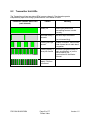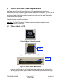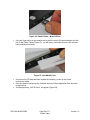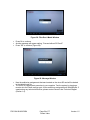
1
Fidelio System Wireless Device for the Hearing and Visually Impaired Installation & User Manual Version 1.5 The English version of this document is the only legally binding version. Translated versions are not legally binding and are for convenience only. FDO.OM.001852.DRM Page 1 of 77 Doremi Labs Version 1.5 Table of Contents 1 2 Introduction ............................................................................................................... 10 1.1 Overview......................................................................................................................... 10 1.2 Fidelio System Parts ..................................................................................................... 10 1.3 Requirements ................................................................................................................ 11 1.4 Contact Information ...................................................................................................... 11 Overview .................................................................................................................... 12 2.1 3 Brief Description ........................................................................................................... 12 2.1.1 Fidelio Transmitter ..............................................................................................................................12 2.1.2 Fidelio Receiver ...................................................................................................................................13 2.1.3 Fidelio Configuration/Charging Station and Tablet ........................................................................14 2.1.4 Fidelio Configuration/Charging Station and Tablet ........................................................................15 2.1.5 Fidelio Audio Interface ........................................................................................................................17 Installation ................................................................................................................. 18 3.1 Charging Station/Touchscreen Tablet ........................................................................ 18 3.1.1 Connection of the Tablet Bracket to the Configuration/Charging Station Base .........................18 3.1.2 Installation of Tablet into the Stand Bracket ...................................................................................18 3.1.3 Power Supply Connection .................................................................................................................19 3.1.4 USB Cable............................................................................................................................................21 3.1.5 Charging the Receiver Batteries .......................................................................................................23 3.2 Assigning the Transmitter Channel ............................................................................ 23 3.2.1 Connections in Projection Booth .......................................................................................................28 3.2.1.1 USB Power ..................................................................................................................................28 3.2.1.2 CaptiView.....................................................................................................................................29 FDO.OM.001852.DRM Page 2 of 77 Doremi Labs Version 1.5 3.3 Fidelio Audio Interface Connections .......................................................................... 29 3.3.1 Server to Audio Interface and then to Theater Sound Processor ................................................29 3.3.1.1 DB25 Connector Setup..............................................................................................................29 3.3.1.2 Audio Interface to Fidelio ..........................................................................................................30 3.3.1.3 RJ45 Connector Setups ............................................................................................................30 3.3.1.4 Audio Interface to Fidelio ..........................................................................................................31 4 Assigning the Receiver to an Auditorium ............................................................. 32 5 Accessibility Track Mapping ................................................................................... 35 5.1 ISDCF/Interop Specs..................................................................................................... 35 5.2 Doremi Server Audio Channel Re-Mapping ............................................................... 35 5.2.1 Channel Mapping Tab ........................................................................................................................37 5.2.1.1 Disabled Configuration ..............................................................................................................37 5.2.1.2 Pre-Defined Mapping Configurations ......................................................................................37 5.2.1.2.1 4 Channels .............................................................................................................................37 5.2.1.2.2 6 Channels .............................................................................................................................38 5.2.1.2.3 7 Channels .............................................................................................................................39 5.2.1.2.4 8 Channels .............................................................................................................................40 5.2.1.2.5 9 Channels .............................................................................................................................41 5.2.1.2.6 ISDCF .....................................................................................................................................42 5.2.1.3 Custom Mapping Configuration ................................................................................................43 5.2.2 Advanced Tab......................................................................................................................................44 5.2.3 SMPTE Packages ...............................................................................................................................45 6 Digital Cinema Naming Convention ....................................................................... 46 7 Technical Specs ....................................................................................................... 48 FDO.OM.001852.DRM Page 3 of 77 Doremi Labs Version 1.5 7.1 System ............................................................................................................................ 48 7.2 Transmitter ..................................................................................................................... 48 7.3 Receiver.......................................................................................................................... 48 LED Lights Description............................................................................................ 49 8 8.1 Receiver LEDs ............................................................................................................... 49 8.2 Transmitter Unit LEDs .................................................................................................. 51 Fidelio Micro SD Card Replacement ...................................................................... 52 9 9.1 Fidelio Tablet – v1.1.2 ................................................................................................... 52 9.2 Fidelio Tablet – v2.2.0 ................................................................................................... 55 Troubleshooting .................................................................................................... 58 10 10.1 Generating a Detailed Report ...................................................................................... 58 10.2 Updating the Fidelio Touchscreen Tablet Software ................................................. 61 10.2.1 10.3 Updating the Fidelio Receiver Firmware .................................................................... 66 10.3.1 10.4 Installation and Update ..................................................................................................................62 Installing Receiver Firmware .........................................................................................................66 Updating the Fidelio Transmitter Firmware ............................................................... 70 10.4.1 Installing Transmitter Firmware ....................................................................................................70 11 Appendix A: Wiring Guide ................................................................................... 74 12 Acronyms ............................................................................................................... 76 13 Document Revision History ................................................................................. 77 FDO.OM.001852.DRM Page 4 of 77 Doremi Labs Version 1.5 Software License Agreement The software license agreement can be found at the following location: http://www.doremilabs.com/support/cinema-support/cinema-warranties/ Hardware Warranty The hardware warranty can be found at the following location: http://www.doremilabs.com/support/cinema-support/cinema-warranties/ FDO.OM.001852.DRM Page 5 of 77 Doremi Labs Version 1.5 WARNING THIS DEVICE MUST BE GROUNDED IMPORTANT Power requirements for electrical equipment vary from area to area. Please ensure that the Fidelio meets the power requirements in the surrounding area. If in doubt, consult a qualified electrician or a Doremi Labs dealer. WARNING: Multiple sources of supply; disconnect all sources before servicing. PROTECTING YOURSELF AND THE FIDELIO Only a qualified professional can install the Fidelio system. Only use the antenna provided by Doremi Labs. The Fidelio transmitter (Fidelio TX) shall be mounted with a separation distance of at least 20cm from any person. The Fidelio receiver (Fidelio RX) antenna shall be at least 5mm away from any person and at least 20mm away from any other antenna. The CaptiView transmitter (if connected to the Fidelio transmitter), or any other antenna, shall at least be 20cm away from the Fidelio transmitter antenna – usage of a USB extension cable will be needed for the CaptiView transmitter connection. Never touch the AC plug with wet hands. Always disconnect the Fidelio from the power supply by pulling on the plug not the cord. Allow only a Doremi Labs dealer or qualified professional engineer to repair or re-assemble the Fidelio. Apart from voiding the warranty, unauthorized engineers might touch live internal parts and receive a serious electric shock. Do not put, or allow anyone to put any object, especially metal objects, into the Fidelio. Use only an AC power supply. Never use a DC power supply. If water or any other liquid is spilled into or onto the Fidelio, disconnect the power and call a Doremi dealer. The unit must be well ventilated and away from direct sunlight. To avoid damage to internal circuitry, as well as the external finish, keep the Fidelio away from direct sources of heat (heater vents, stoves, radiators). Avoid using flammable aerosols near the Fidelio. They can damage the surface area and may ignite. Do not use denatured alcohol, paint thinner or similar chemicals to clean the Fidelio. This can damage the unit. Modification of this equipment is dangerous and can result in the functions of the Fidelio being impaired. Never attempt to modify the equipment in any way. In order to ensure optimum performance of the Fidelio, select the setup location carefully and make sure the equipment is used properly. Avoid setting up the Fidelio in the following locations: In a humid or dusty environment. In a room with poor ventilation. On a surface which is not level. Inside a moving vehicle where it will be subject to vibration. In an extremely hot or cold environment. FDO.OM.001852.DRM Page 6 of 77 Doremi Labs Version 1.5 FCC Warning - Fidelio Transmitter and Receiver (Fidelio TX / Fidelio RX) Be aware that any change or modification not expressly approved by Doremi Labs could void the user's authority to operate the equipment. This device complies with part 15 of the FCC Rules. Operation is subject to the following two conditions: (1) This device may not cause harmful interference, and (2) this device must accept any interference received, including interference that may cause undesired operation. Note: This equipment has been tested and found to comply with the limits for a Class B digital device, pursuant to part 15 of the FCC Rules. These limits are designed to provide reasonable protection against harmful interference in a residential installation. This equipment generates, uses and can radiate radio frequency energy and, if not installed and used in accordance with the instructions, may cause harmful interference to radio communications. However, there is no guarantee that interference will not occur in a particular installation. If this equipment does cause harmful interference to radio or television reception, which can be determined by turning the equipment off and on, the user is encouraged to try to correct the interference by one or more of the following measures: —Reorient or relocate the receiving antenna. —Increase the separation between the equipment and receiver. —Connect the equipment into an outlet on a circuit different from that to which the receiver is connected. —Consult the dealer or an experienced radio/TV technician for help. IC Statement – Fidelio Transmitter and Receiver (Fidelio TX / Fidelio RX) This device complies with Industry Canada licence-exempt RSS standard(s). Operation is subject to the following two conditions: (1) this device may not cause interference, and (2) this device must accept any interference, including interference that may cause undesired operation of the device. Le présent appareil est conforme aux CNR d'Industrie Canada applicables aux appareils radio exempts de licence. L'exploitation est autorisée aux deux conditions suivantes : (1) l'appareil ne doit pas produire de brouillage, et (2) l'utilisateur de l'appareil doit accepter tout brouillage radioélectrique subi, même si le brouillage est susceptible d'en compromettre le fonctionnement. FDO.OM.001852.DRM Page 7 of 77 Doremi Labs Version 1.5 Under Industry Canada regulations, this radio transmitter may only operate using an antenna of a type and maximum (or lesser) gain approved for the transmitter by Industry Canada. To reduce potential radio interference to other users, the antenna type and its gain should be so chosen that the equivalent isotropically radiated power (e.i.r.p.) is not more than that necessary for successful communication. Conformément à la réglementation d'Industrie Canada, le présent émetteur radio peut fonctionner avec une antenne d'un type et d'un gain maximal (ou inférieur) approuvé pour l'émetteur par Industrie Canada. Dans le but de réduire les risques de brouillage radioélectrique à l'intention des autres utilisateurs, il faut choisir le type d'antenne et son gain de sorte que la puissance isotrope rayonnée équivalente (p.i.r.e.) ne dépasse pas l'intensité nécessaire à l'établissement d'une communication satisfaisante. FDO.OM.001852.DRM Page 8 of 77 Doremi Labs Version 1.5 FDO.OM.001852.DRM Page 9 of 77 Doremi Labs Version 1.5 1 Introduction 1.1 Overview The Doremi Fidelio is an audio distribution system carrying two stereo channels from a single transmitter unit to a number of receiver units. This product was designed to enhance and assist people who are visually and/or hearing impaired in a motion picture theater. This manual will guide you through the steps necessary to physically set up and connect the Fidelio device. The entire Fidelio setup consists of a Transmitter, Receiver, Charging/Configuration Station, Touch Screen Tablet, Audio Interface Box and Headset. The Receiver device docks to the charger, which can be used for multiple purposes including: Recharging the battery Configuration Upgrading firmware Production tests 1.2 Fidelio System Parts (1) - Fidelio Transmitter – FIDELIO-TX (1) - Fidelio Transmitter Antenna -FIDELIO-TX-ANT (1) - 2 meter USB cable A-B -CBL-USB-GHX (1) - Fidelio Audio Interface Box – FIDELIO-AI (1) - 1 meter DB25 cable, M-F, 1-to-1 pin out -CBL-DB25M-DB25F-2.5 (2) - 1-meter CAT5 Ethernet cable -CBL-ENET-1M (1) - Fidelio Receiver with Belt-clip – FIDELIO-RX (1) - Fidelio Headphone - FIDELIO-RX-HP (1) - Fidelio Charging Station – FIDELIO-WAC (1) - 7” Tablet Mounting Bracket - MTL-FIDELIO-WAC-BRTS (4) - M3x6 Flat Head Machine Screws, black - M3x6MM-BFH (2) - 4” Nylon tie-wrap, black -CBL-TIE-4IN14 (1) - 7” Touchscreen Tablet Computer (v1.1.2 or v2.2.0) – FIDELIO-TS (1) – For Tablet v1.1.2 - USB Cable, Mini A - Type A - No Part Number (1) – For Tablet v2.2.0 - USB Cable, Micro B – Type A–CBL-FIDELIO-TS-MICROB-AF (1) - 5V Power Supply with dual connectors - PS-HDVI (Modified) (1) - AC Power Cable - Power Cable (1) - USB Power Adapter- CPTVW-ACC FDO.OM.001852.DRM Page 10 of 77 Doremi Labs Version 1.5 1.3 Requirements To perform audio mapping, the Doremi digital cinema server must be running software version 2.2.2 or higher. The installer will need to provide two (2) BNC to BNC cables for each transmitter being installed at the complex. Length of these cables will depend on your specific installation requirement, specifically the distance the transmitter will be from the Fidelio Audio Interface box. 1.4 Contact Information If in need of help or assistance, please contact your nearest Doremi Labs Technical Support at: USA 24/7 Technical Support line: + 1-866-484-4004 Technical Support Email: [email protected] Europe 24/7 Technical Support line: + 33 (0) 492-952-847 Technical Support Link: http://support.doremitechno.org/ticketing Japan Technical Support line: + 044-966-4855 Technical Support Email: [email protected] Australia ~ China ~ India ~ Indonesia ~ Korea ~ Malaysia ~ New Zealand ~ Philippines ~ Singapore ~ Taiwan ~ Thailand Technical Support Email: [email protected] FDO.OM.001852.DRM Page 11 of 77 Doremi Labs Version 1.5 2 Overview 2.1 Brief Description The following is a brief description of each of the components, with pictures, that make up the Fidelio setup. Begin the installation process by carefully unwrapping and removing all Fidelio components from the box. Double-check and confirm that all the parts and components are present. 2.1.1 Fidelio Transmitter The Fidelio Transmitter is the device that will transmit the Hearing Impaired (HI) or Visually Impaired Narrative (VI-N) audio track from the Digital Cinema Package (DCP) to the Fidelio Receiver (Figure 1). You will need one Fidelio Transmitter for every auditorium you choose to enable. USB Configuration Port Articulating Antenna CaptiView Transmitter Input AES IN 2 AES IN 1 Figure 1: Fidelio Transmitter FDO.OM.001852.DRM Page 12 of 77 Doremi Labs Version 1.5 2.1.2 Fidelio Receiver The Fidelio Receiver (Figure 2 and Figure 3) is the device that an audience member obtains from the theater customer service kiosk. This receiver is to be configured using the touchscreen tablet interface for the auditorium number that is enabled for Fidelio transmission. The patron then takes the receiver into the assigned auditorium to receive the transmission from the Fidelio Transmitter that has been configured for that assigned auditorium within the multiplex. Depending on the configuration assignment, the receiver will either receive the Hearing Impaired (HI) audio track, the Visually Impaired Narrative (VI-N) audio track or both the HI + VIN audio tracks. Removable Belt Clip Charger Contacts Figure 2: Fidelio Receiver and Rear View Headphone Jack (1/8”) Power On/Off Button Power Indicator LED Volume Toggle Switch Figure 3: Fidelio Receiver – Top View and Side View FDO.OM.001852.DRM Page 13 of 77 Doremi Labs Version 1.5 2.1.3 Fidelio Configuration/Charging Station and Tablet The Fidelio configuration/charging stations are used to charge and configure Fidelio receivers. The touchscreen tablet (original tablet v1.1.2 - Figure 4) is used to display the graphical user interface (GUI) when configuring each receiver. Refer to Figure 5 for configuration/charging station containing the latest version of the Fidelio tablet. Figure 4: Fidelio Configuration/Charging Station with Tablet (v1.1.2) Figure 5: Fidelio Configuration/Charging Station with Tablet (v2.2.0) FDO.OM.001852.DRM Page 14 of 77 Doremi Labs Version 1.5 2.1.4 Fidelio Configuration/Charging Station and Tablet USB Hub Port Power Receptacle Figure 6: Fidelio Configuration/Charging Station - Side View Receiver Configuration Port Receiver Charging Ports Figure 7: Fidelio Configuration/Charging Station - Top View Tablet (v. 1.1.2) Home Button Figure 8: Fidelio Tablet (v. 1.1.2) – Front View FDO.OM.001852.DRM Page 15 of 77 Doremi Labs Version 1.5 Figure 9: Fidelio Tablet (V2.2.0) – Front View Charging Port HDMI Port Not Used On/Off Power Button Mini USB Port Headphone Jack (Not Used) MicroSD Card Port Figure 10: Fidelio Tablet (v1.1.2 – Side View) Headphone Jack (Not Used) HDMI Port Not Used On/Off Power Button Volume Rocker Micro USB Port Charging Port Figure 11: Fidelio Tablet (v2.2.0 – Side View) FDO.OM.001852.DRM Page 16 of 77 Doremi Labs Version 1.5 2.1.5 Fidelio Audio Interface Female BNC Connector AES OUT CH 15/16 RJ45 Port AES THRU CH 9-14 DB25 Connector AES THRU Ch. 1-6, Ch. 914 Female BNC Connector AES OUT CH 7/8 RJ45 Port AES THRU CH 1-6 Figure 12: Fidelio Audio Interface – Front View RJ45 Port AES IN CH 9-16 DB25 Connector AES IN CH 1-16 RJ45 Port AES IN CH 1-8 Figure 13: Fidelio Audio Interface – Rear View FDO.OM.001852.DRM Page 17 of 77 Doremi Labs Version 1.5 3 Installation Follow the steps below to set up the Fidelio System. 3.1 Charging Station/Touchscreen Tablet You will need to first connect the touchscreen tablet to the charging/configuration base using the tablet bracket. 3.1.1 Connection of the Tablet Bracket to the Configuration/Charging Station Base Place the Fidelio configuration/charging station base upside down near the edge of a table so that the tablet bracket can hang down and sit flush to the bottom of the base. Line up the 4 (four) holes of the tablet mounting bracket to the 4 (four) holes of the charging/configuration base. Using a Phillips screwdriver, carefully secure the tablet mounting bracket to the charging/configuration base using the (4) - M3x6 Black Flat Head Machine Screws provided. 3.1.2 Installation of Tablet into the Stand Bracket Turn the Fidelio configuration/charging station base over so that it is sitting upright. Loosen the tablet clip screws (Figure 14). Slide the touchscreen tablet from the right-hand side of the bracket grooves until the tablet is centered on its mounting bracket. Tighten the tablet clip screws to secure the touchscreen tablet in the bracket. Tablet Clip and Tightening Screws Figure 14: Charging Station Rear View FDO.OM.001852.DRM Page 18 of 77 Doremi Labs Version 1.5 3.1.3 Power Supply Connection Plug the “Y” Power Supply cable into the port labeled “Power” on the charging/configuration base (Figure 15). Figure 15: Power Port Plug the small end of the connector with the yellow tip into the touchscreen tablet port labeled “DC IN 5V,” which is located on the right-hand side of the touchscreen tablet (v.1.1.2 Figure 16; v2.2.0 Figure 17). DC IN 5V Tablet Power Connector Micro USB Cable Figure 16: Tablet (v1.1.2) Power Connector FDO.OM.001852.DRM Page 19 of 77 Doremi Labs Version 1.5 Micro USB Cable DC IN 5V Tablet Power Cable Figure 17: Tablet (v2.2.0) Power Connector Using a 4” Nylon black tie-wrap provided, slip the tie-wrap though the eyelet (Figure 18) to secure the cable to the tablet mounting bracket. Cable Tie-Wrap Eyelet Figure 18: Eyelet for Cable Tie-Wrap FDO.OM.001852.DRM Page 20 of 77 Doremi Labs Version 1.5 3.1.4 USB Cable Figure 19: USB Connectors Plug the large end (Type B) of the USB cable into the Fidelio configuration/charging station base and the smaller end (Type Mini B) into the micro USB port located on the right-hand side of the Fidelio touchscreen tablet (Figure 19 and Figure 20). This USB cable connection is essential to configuring Fidelio Receivers to specific auditoriums along with their audio channel assignments. Note: The USB cable may actually be an A to B cable with an adapter to convert to a MiniB/Micro USB cable. FDO.OM.001852.DRM Page 21 of 77 Doremi Labs Version 1.5 USB (Type Mini B) Cable USB (Type B) Cable Figure 20: Fidelio Charging Station and Tablet (v1.1.2) Micro-USB Cable USB (Type B) Cable Figure 21: Fidelio Charging Station and Tablet (v2.2.0) FDO.OM.001852.DRM Page 22 of 77 Doremi Labs Version 1.5 3.1.5 Charging the Receiver Batteries After you have plugged one end of the power cable into the Fidelio configuration/charging station base, the other end of the cable needs to be plugged into a wall outlet for power. Place any Fidelio Receiver requiring a charge into one of the base's 10 charging receptacles. Make sure that each receiver is fully seated in the charging receptacle to ensure good contact between the base and receiver’s charging contacts. When the Fidelio Receiver is placed securely into one of the ten charging receptacles on a powered charging station, a flashing green LED located next to the Power button on the top of the transmitter will indicate that battery charging is active. Charge all Fidelio Receivers until their batteries are full. A steadily illuminated green Power LED will indicate that the battery is fully charged. It takes about an hour and a half to fully charge the Fidelio. The Fidelio Receiver will function for 12 hours, playing at max volume with a fully charged battery. 3.2 Assigning the Transmitter Channel Connect the Fidelio Transmitter antenna to the backside of the transmitter where it is labeled “ANTENNA.” Do so by threading the antenna's silver serrated collar into the gold threaded connection on the Fidelio Transmitter. Once connected, you can articulate the antenna if needed. Upon the initial set up, each Fidelio Transmitter will need to be assigned to a specific auditorium. To perform this operation, plug the large end (Type B) of the USB cable into the Fidelio Transmitter and the smaller end (Type Mini B) into the micro USB port located on the right-hand side of the Fidelio touchscreen tablet (Figure 20). Power up the Fidelio touchscreen tablet by depressing the power switch. Refer to the Figure 8 (v1.1.2) and Figure 9 (v2.2.0) for the location of the power button. Note: You will need to keep pressure on the switch until the Android splash screen comes up. FDO.OM.001852.DRM Page 23 of 77 Doremi Labs Version 1.5 After the Fidelio touchscreen tablet has finished booting up, you will need to unlock the screen by using your finger on the unlock padlock icon and sliding the unlock padlock icon in the up direction on the touch screen (Figure 22). Unlock Padlock Icon Figure 22: Tablet (v 1.1.2) Unlock Padlock Icon Unlock Padlock Icon Figure 23: Tablet (v2.2.0) Unlock Padlock Icon Once unlocked, you will be presented with the application icons screen. FDO.OM.001852.DRM Page 24 of 77 Doremi Labs Version 1.5 Using your finger, touch the Fidelio application icon to launch the application. Fidelio Application Icon Home Icon Figure 24: Fidelio Application Icon At first you will see a message saying, “Looking for Fidelio Devices” (Figure 25). Next, you will see a message saying, “Identifying Fidelio Device.” Figure 25: Looking for Fidelio Devices Screen FDO.OM.001852.DRM Page 25 of 77 Doremi Labs Version 1.5 Once the Fidelio Transmitter is recognized, a screen will appear that will indicate what auditorium number has been assigned to the transmitter. Simply touch the Change button on the screen to change the auditorium assignment (Figure 26). Figure 26: Transmitter Change Auditorium Screen Note: The frequency band is configured at factory and cannot be changed by the user. When you have touched the change button, you will be presented with the Select Auditorium screen. You can select auditorium assignments from 01 to 32. Note: Any number with a blue square indicates that the auditorium number has been previously assigned to a transmitter within your complex, not just the one currently plugged in (Figure 27). Figure 27: Transmitter Select Auditorium Screen Once you have assigned the correct auditorium number, press the Home button (Refer to Figure 8 for v1.1.2; Refer to Figure 24 for v2.2.0) on the tablet and disconnect the USB cable connected to the transmitter. Label the transmitter with the appropriate auditorium assignment as a reference so that it is installed in the correct projection booth. FDO.OM.001852.DRM Page 26 of 77 Doremi Labs Version 1.5 To configure another transmitter, launch the Fidelio application and connect the transmitter to the configuration tablet. Follow the same steps mentioned above. Once you have configured all your Fidelio transmitters, power down the Fidelio tablet by depressing and holding the tablet Power button until the Power Off option appears on the tablet screen (Figure 28). Figure 28: Power Off Screen - Tablet v1.1.2 Depress the Power Off selection and then press the OK button to complete the process (Figure 29 – v1.1.2; Figure 30 – v2.2.0). Figure 29: Power Off OK Button - Tablet v1.1.2 FDO.OM.001852.DRM Page 27 of 77 Doremi Labs Version 1.5 Figure 30: Power Off OK Button - Tablet v2.2.0 3.2.1 Connections in Projection Booth 3.2.1.1 USB Power First you will need to plug the large end (Type B) of the USB cable into the USB port located on the front of the Fidelio Transmitter box (Figure 31). Figure 31: USB Cable Plugged into Fidelio Transmitter The other end of the Type A connector will need to be plugged into the USB Power Adapter provided or to one of the USB ports on the Digital Cinema Server. If you are using the USB Power Adapter, plug this into an AC outlet. One of these connections will provide power to the Fidelio Transmitter box. FDO.OM.001852.DRM Page 28 of 77 Doremi Labs Version 1.5 3.2.1.2 CaptiView If the auditorium you’re installing the Fidelio audio distribution system into has a CaptiView transmitter installed, you can plug the CaptiView transmitter into the port labeled “CaptiView” on the front of the Fidelio Transmitter box. Note: The Fidelio Transmitter box must be connected to the Doremi Digital Cinema Server via a USB cable for the CaptiView transmitter to transmit the CC (Closed Captioned) information to the CaptiView Display(s) in the auditorium. The CaptiView transmitter shall at least be 20cm away from the Fidelio transmitter antenna – usage of a USB extension cable will be needed for the CaptiView transmitter connection. 3.3 Fidelio Audio Interface Connections The Fidelio Audio Interface box has the ability to interface with both the DB25 connector and RJ-45 connectors. In either case, the Fidelio Audio Interface box is used to access the AES audio channels, 15/16 & 7/8, to then transmit to the Fidelio Receiver. 3.3.1 Server to Audio Interface and then to Theater Sound Processor 3.3.1.1 DB25 Connector Setup If your setup consists of using the DB25 cable, you will need to disconnect the DB25 cable from your Doremi digital cinema server and connect this cable to the connector on the Fidelio Audio Interface Box labeled, AES THRU CH 1-6, CH 9-14 (Figure 32). The other end on this cable is to remain connected to your audio processor. Using the short DB25 cable provided, connect one end into the AES OUT on the Doremi server and the other end into the AES IN connector on the Fidelio Audio Interface box. Figure 32: Audio Interface for DB25 Setups FDO.OM.001852.DRM Page 29 of 77 Doremi Labs Version 1.5 3.3.1.2 Audio Interface to Fidelio You will now need to connect one BNC cable (NOT provided) to the Fidelio Audio Interface Box BNC connector labeled, “AES OUT CH 15/16” (Figure 32). Connect the other end of this BNC cable to the Fidelio Transmitter box BNC connector labeled, “AES IN 2” (Figure 33). Now connect another BNC cable (NOT provided) to the Fidelio Audio Interface Box BNC connector labeled, “AES OUT CH 7/8” (Figure 32). Connect the other end of this BNC cable to the Fidelio Transmitter box BNC connector labeled, “AES IN 1” (Figure 33). Figure 33: AES Connection on Fidelio Transmitter Your connections concerning the projection booth are now complete. 3.3.1.3 RJ45 Connector Setups If your setup consists of using RJ45 connectors, you will need to disconnect the RJ45 cables from your Doremi Integrated Media Block (IMB). Then connect these cables to the connectors on the Fidelio Audio Interface Box labeled, “AES THRU CH 1-6,” and the other cable to the connector that reads, “AES THRU CH 9-14” (Figure 34). The other ends on these cables are to remain connected to your audio processor, respectively. Using the short RJ45 cable provided, connect one cable into the CH 1-8 AES OUT on the Doremi IMB and the other end into the AES IN CH 1-8 connector on the Fidelio Audio Interface box. Using the other short RJ45 cable provided, connect one cable into the CH 9-16 AES OUT on the Doremi IMB and the other end into the AES IN CH 9-16 connector on the Fidelio Audio Interface box. FDO.OM.001852.DRM Page 30 of 77 Doremi Labs Version 1.5 Figure 34: Audio Interface for RJ45 Setups 3.3.1.4 Audio Interface to Fidelio You will now need to connect one BNC cable (NOT provided) to the Fidelio Audio Interface Box BNC connector labeled, “AES OUT CH 15/16” (Figure 34). Connect the other end of this BNC cable to the Fidelio Transmitter box BNC connector labeled, “AES IN 2” (Figure 33). Now connect another BNC cable (NOT provided) to the Fidelio Audio Interface Box BNC connector labeled, “AES OUT CH 7/8” (Figure 34). Connect the other end of this BNC cable to the Fidelio Transmitter box BNC connector labeled, “AES IN 1” (Figure 33). Your connections concerning the projection booth are now complete. FDO.OM.001852.DRM Page 31 of 77 Doremi Labs Version 1.5 Assigning the Receiver to an Auditorium 4 First you will need to plug the large end (Type B) of the USB cable into the USB port located on the right-hand side of the Fidelio charging station base and the smaller end (Mini A) into the micro USB port located on the right-hand side of the Fidelio touchscreen tablet (Figure 20). Power up the Fidelio touchscreen tablet by depressing the power switch located on the top right-hand side of the tablet (Figure 10). Note: You will need to keep pressure on the switch until the Android splash screen comes up. After the Fidelio touchscreen tablet has finished booting up, you will need to unlock the screen by using your finger on the unlock padlock icon and sliding up on the touch screen (Figure 22). Once unlocked, you will be presented with the Fidelio application icon screen. Using your finger, touch the Fidelio application icon to launch the application (Figure 24). The tablet will display a message saying, “Looking for Fidelio Devices” (Figure 25). Place a Fidelio Receiver into the port labeled, “Configuration Port,” on the Fidelio charging station base. The tablet will then display the Receiver display screen. This screen will provide you with the Auditorium and Channel assignments for the Receiver (Figure 35). Figure 35: Receiver Auditorium and Channel Assignments Screen To change their assignments, simply touch the corresponding Change button (Figure 35). FDO.OM.001852.DRM Page 32 of 77 Doremi Labs Version 1.5 When you select the Auditorium Change button, you will be presented with a Select Auditorium screen that will display all theater numbers assigned to a Fidelio Transmitter. (Figure 36). Figure 36: Receiver Auditorium Assignment Screen With your finger, touch the theater number you wish to assign to the Fidelio receiver that is plugged into the Configuration Port. The tablet will then display the Receiver screen (Figure 37). Figure 37: Receiver Channel Assignment Screen When you select the Channel Change button, you will be presented with the Select Channel screen (Figure 38). FDO.OM.001852.DRM Page 33 of 77 Doremi Labs Version 1.5 Figure 38: Receiver Select Channel Assignment Screen You can select from one of the following options: o Ch. 1a (HI) o Ch. 2a (HI) o Ch. 1b (VI-N) o Ch. 2b (VI-N) o Ch.1 (Stereo) o Ch.2 (Stereo) The selection you make will be based on your Fidelio wiring setup and your Digital Cinema Player's audio mapping. In other words, assuming that you use the audio wiring setup as described in this manual, and the Digital Cinema Package playing back has been mastered with the HI audio track on channel 7 and the VI-N audio track on channel 8, your Digital Cinema Player's audio mapping will be configured similar to the recommendations in Figure 39. Selecting Ch.1a will provide the audio channel 7 in L&R mono to the receiver. Selecting Ch.2a will provide the audio channel 15 in L&R mono to the receiver. Selecting Ch.1b will provide the audio channel 8 in L&R mono to the receiver. Selecting Ch.2b will provide the audio channel 16 in L&R mono to the receiver. Selecting Ch.1 (Stereo) will provide the audio channels 7 & 8 to the receiver. (7 to headset Left, 8 to headset Right). Selecting Ch.2 (Stereo) will provide the audio channels 15 & 16 to the receiver. (15 to headset Left, 16 to headset Right). After you have selected your theater and channel assignments, the Receiver can now be removed from the configuration port and handed to the customer/patron. FDO.OM.001852.DRM Page 34 of 77 Doremi Labs Version 1.5 5 Accessibility Track Mapping 5.1 ISDCF/Interop Specs Please refer to Figure 39 for recommendations for use in all Interop DCP compositions. Note: The audio channel numbers for Interop DCP's map one-to-one to the audio outputs of a player. For this reason, the table also identifies the recommended audio wiring in cinemas. Figure 39: Interop/ISDCF Recommendations 5.2 Doremi Server Audio Channel Re-Mapping The following will assist you to re-map your audio on the Doremi Cinema Player. To open the Audio Configuration application, go to Menu → Control Panel → Audio Configuration (Figure 40). FDO.OM.001852.DRM Page 35 of 77 Doremi Labs Version 1.5 Figure 40: Control Panel with Audio Configuration Icon Selected An admin password and confirmation will be needed to perform the operation. The Audio Configuration window will appear (Figure 41). Template Mapping Save Button Advanced Tab Channel Mapping Tab Figure 41: Audio Configuration - Default Setting When first launched, the Audio Configuration application opens in the Channel Mapping tab. The Template Mapping will be set to Disabled. Note: All the templates, except Disabled, can be modified directly instead of having to select Custom. Once the template is edited, the Template Mapping will read Custom. Available configurations include: Disabled: This setting is the default and as such cannot be mapped (Section 5.2.1.1). FDO.OM.001852.DRM Page 36 of 77 Doremi Labs Version 1.5 4 channels: This is a pre-set configuration. 6 channels: This is a pre-set configuration. 7 channels: This is a pre-set configuration. 8 channels: This is a pre-set configuration. 9 channels: This is a pre-set configuration. ISDCF: This is a pre-set configuration. Custom: This setting allows the user to create a custom audio configuration. 5.2.1 Channel Mapping Tab 5.2.1.1 Disabled Configuration Figure 42: Disabled Configuration Disabled: This setting is the default and as such cannot be mapped (Figure 42). The Disabled mapping configuration will perform pass-through mapping, meaning channel number "X" of the CPL audio track will be routed to audio output number "X" (variable) of the server. "X" being a number between 1 and 16. When the configuration is grayed-out, the user cannot change the configuration. 5.2.1.2 Pre-Defined Mapping Configurations 5.2.1.2.1 4 Channels This configuration is defined as follows (Figure 43): Ch.01 is Left (L): Output ch.01 will be playing the CPL's Left (L) audio channel. Ch.02 is Right (R): Output ch.02 will be playing the CPL's Right (R) audio channel. Ch.03 is Center (C): Output ch.03 will be playing the CPL's Center (C) audio channel. Ch.04 is Input: ch.04 is pass-through, meaning the output channel “X” will be playing the CPL's audio channel “X.” FDO.OM.001852.DRM Page 37 of 77 Doremi Labs Version 1.5 Ch.05 is Surround (S): Output ch.05 will be playing the CPL's Surround (S) audio channel. Ch.06 – Ch.14: These channels are pass-through, meaning the output channel “X” will be playing the CPL's audio channel “X.” “X” will be a value between 6 and 14. Ch.15 is HI: Output ch.15 will be playing the CPL's Hearing Impaired (HI) audio channel. Ch.16 is VI: Output ch.16 will be playing the CPL's Narration (VI) audio channel. Figure 43: Audio Mapping Set to 4 Channels 5.2.1.2.2 6 Channels This configuration is defined as follows (Figure 44): Ch.01 is Left (L): Output ch.01 will be playing the CPL's Left (L) audio channel. Ch.02 is Right (R): Output ch.02 will be playing the CPL's Right (R) audio channel. Ch.03 is Center (C): Output ch.03 will be playing the CPL's Center (C) audio channel. Ch.04 is LFE/Screen (Sub-Woofer): Output ch.04 will be playing the CPL's LFE/Screen (Sub-Woofer) audio channel. Ch.05 is Left Surround (Ls): Output ch.05 will be playing the CPL's Left Surround (Ls) audio channel. Ch.06 is Right Surround (Rs): Output ch.06 will be playing the CPL's Right Surround (Rs) audio channel. Ch.07 – Ch.14: These channels are pass-through, meaning the output channel “X” will be playing the CPL's audio channel “X.” “X” will be a value between 7 and 14. Ch.15 is HI: Output ch.15 will be playing the CPL's Hearing Impaired (HI) audio channel. Ch.16 is VI: Output ch.16 will be playing the CPL's Narration (VI) audio channel. FDO.OM.001852.DRM Page 38 of 77 Doremi Labs Version 1.5 Figure 44: Audio Mapping Set to 6 Channels 5.2.1.2.3 7 Channels This configuration is defined as follows (Figure 45): Ch.01 is Left (L): Output ch.01 will be playing the CPL's Left (L) audio channel. Ch.02 is Right (R): Output ch.02 will be playing the CPL's Right (R) audio channel. Ch.03 is Center (C): Output ch.03 will be playing the CPL's Center (C) audio channel. Ch.04 is LFE/Screen (Sub-Woofer): Output ch.04 will be playing the CPL's LFE/Screen (Sub-Woofer) audio channel. Ch.05 is Left Surround (Ls): Output ch.05 will be playing the CPL's Left Surround (Ls) audio channel. Ch.06 is Right Surround (Rs): Output ch.06 will be playing the CPL's Right Surround (Rs) audio channel. Ch.07 is Input: ch.07 is pass-through, meaning the output channel “X” will be playing the CPL's audio channel “X.” Ch.08 is Input: ch.08 is pass-through, meaning the output channel “X” will be playing the CPL's audio channel “X.” Ch.09 is Center Surround (Cs): Output ch.09 will be playing the CPL's Center Surround (Cs) audio channel. Ch.10 – Ch.14: These channels are pass-through, meaning the output channel “X” will be playing the CPL's audio channel “X.” “X” will be a value between 10 and 14. Ch.15 is HI: Output ch.15 will be playing the CPL's Hearing Impaired (HI) audio channel. Ch.16 is VI: Output ch.16 will be playing the CPL's Narration (VI) audio channel. FDO.OM.001852.DRM Page 39 of 77 Doremi Labs Version 1.5 Figure 45: Audio Mapping Set to 7 Channels 5.2.1.2.4 8 Channels This configuration is defined as follows (Figure 46): Ch.01 is Left (L): Output ch.01 will be playing the CPL's Left (L) audio channel. Ch.02 is Right (R): Output ch.02 will be playing the CPL's Right (R) audio channel. Ch.03 is Center (C): Output ch.03 will be playing the CPL's Center (C) audio channel. Ch.04 is LFE/Screen (Sub-Woofer): Output ch.04 will be playing the CPL's LFE/Screen (Sub-Woofer) audio channel. Ch.05 is Left Surround (Ls): Output ch.05 will be playing the CPL's Left Surround (Ls) audio channel. Ch.06 is Right Surround (Rs): Output ch.06 will be playing the CPL's Right Surround (Rs) audio channel. Ch.07 is Left Center (Lc): Output ch.07 will be playing the CPL's Left Center (Lc) audio channel. Ch.08 is Right Center (Rc): Output ch.08 will be playing the CPL's Right Center (Rc) audio channel. Ch.9 – Ch.14: These channels are pass-through, meaning the output channel “X” will be playing the CPL's audio channel “X.” “X” will be a value between 9 and 14. Ch.15 is HI: Output ch.15 will be playing the CPL's Hearing Impaired (HI) audio channel. Ch.16 is VI: Output ch.16 will be playing the CPL's Narration (VI) audio channel. FDO.OM.001852.DRM Page 40 of 77 Doremi Labs Version 1.5 Figure 46: Audio Mapping Set to 8 Channels 5.2.1.2.5 9 Channels This configuration is defined as follows (Figure 47): Ch.01 is Left (L): Output ch.01 will be playing the CPL's Left (L) audio channel. Ch.02 is Right (R): Output ch.02 will be playing the CPL's Right (R) audio channel. Ch.03 is Center (C): Output ch.03 will be playing the CPL's Center (C) audio channel. Ch.04 is LFE/Screen (Sub-Woofer): Output ch.04 will be playing the CPL's LFE/Screen (Sub-Woofer) audio channel. Ch.05 is Left Surround (Ls): Output ch.05 will be playing the CPL's Left Surround (Ls) audio channel. Ch.06 is Right Surround (Rs): Output ch.06 will be playing the CPL's Right Surround (Rs) audio channel. Ch.07 is Left Center (Lc): Output ch.07 will be playing the CPL's Left Center (Lc) audio channel. Ch.08 is Right Center (Rc): Output ch.08 will be playing the CPL's Right Center (Rc) audio channel. Ch.09 is Center Surround (Cs): Output ch.09 will be playing the CPL's Center Surround (Cs) audio channel. Ch.10 – Ch.14: These channels are pass-through, meaning the output channel “X” will be playing the CPL's audio channel “X.” “X” will be a value between 10 and 14. Ch.15 is HI: Output ch.15 will be playing the CPL's Hearing Impaired (HI) audio channel. Ch.16 is VI: Output ch.16 will be playing the CPL's Narration (VI) audio channel. FDO.OM.001852.DRM Page 41 of 77 Doremi Labs Version 1.5 Figure 47: Audio Mapping Set to 9 Channels 5.2.1.2.6 ISDCF This configuration is defined as follows (Figure 48): Ch.01 is Left (L): Output ch.01 will be playing the CPL's Left (L) audio channel. Ch.02 is Right (R): Output ch.02 will be playing the CPL's Right (R) audio channel. Ch.03 is Center (C): Output ch.03 will be playing the CPL's Center (C) audio channel. Ch.04 is LFE/Screen (Sub-Woofer): Output ch.04 will be playing the CPL's LFE/Screen (Sub-Woofer) audio channel. Ch.05 is Left Surround (Ls): Output ch.05 will be playing the CPL's Left Surround (Ls) audio channel. Ch.06 is Right Surround (Rs): Output ch.06 will be playing the CPL's Right Surround (Rs) audio channel. Ch.07 is HI: Output ch.07 will be playing the CPL's Hearing Impaired (HI) audio channel. Ch.08 is VI: Output ch.08 will be playing the CPL's Narration (VI) audio channel. Ch.09 is Left Center (Lc): Output ch.09 will be playing the CPL's Left Center (Lc) audio channel. Ch.10 is Right Center (Rc): Output ch.10 will be playing the CPL's Right Center (Rc) audio channel. Ch.11 is Left Rear Surround (Lrs): Output ch.11 will be playing the CPL's Left Rear Surround (Lrs) audio channel. Ch.12 is Right Rear Surround (Rrs): Output ch.12 will be playing the CPL's Right Rear Surround (Rrs) audio channel. Ch.13 is Input: ch.13 is pass-through, meaning the output channel “X” will be playing the CPL's audio channel “X.” FDO.OM.001852.DRM Page 42 of 77 Doremi Labs Version 1.5 Ch.14 is Input: ch.14 is pass-through, meaning the output channel “X” will be playing the CPL's audio channel “X.” Ch.15 is Input: ch.15 is pass-through, meaning the output channel “X” will be playing the CPL's audio channel “X.” Ch.16 is Input: ch.16 is pass-through, meaning the output channel “X” will be playing the CPL's audio channel “X.” Figure 48: Audio Mapping Set to ISDCF 5.2.1.3 Custom Mapping Configuration Click on the drop-down menu and select Custom. The following window will appear (Figure 49). Figure 49: Custom Mapping FDO.OM.001852.DRM Page 43 of 77 Doremi Labs Version 1.5 Click on the Browse button ("...") for each output channel (ch.01-ch.16) to select the CPL's audio channel, using its label that is to be routed (Figure 50). Figure 50: Custom Mapping Parameters 5.2.2 Advanced Tab This tab allows the user to add a delay between audio and video by dragging the cursor to the desired delay on the graphical cursor that allows values between -200 milliseconds and 200 milliseconds. All audio tracks will get the same delay. You cannot add separate delays for each track. After the delay has been configured, click on the Save button to save the audio delay. The selected audio delay is shown in numeric characters below the cursor field (Figure 51). Figure 51: Advanced Tab FDO.OM.001852.DRM Page 44 of 77 Doremi Labs Version 1.5 Positive Value: The audio will be heard behind the video action. Negative Value: Indicates that the audio is heard ahead of the video action. The recommended value that almost matches all setups is 80 milliseconds. 5.2.3 SMPTE Packages Note: The audio selection should reflect the audio package in number of audio channels. You can change the Template Mapping setting by clicking on the list-menu and selecting the desired setting (Figure 42). Make sure to click the Save button to ensure the configuration is saved (Figure 41). The list of possible labels that can be routed (if present in the audio MXF file) are defined by SMPTE as follows: o L/Left o R/Right o C/Center o LFE Screen o Ls/Left surround o Rs/Right surround o Lc/Left center o Rc/Right center o Cs/Center surround o Rrs/Right rear surround o Lrs/Left rear surround o HI/Hearing Impaired o VI-N/Visual Impaired-Narration FDO.OM.001852.DRM Page 45 of 77 Doremi Labs Version 1.5 6 Digital Cinema Naming Convention Most professionally mastered DCP's comply with the Digital Cinema Naming Convention, which assists the operator with determining the technical components of the content (Figure 52). The following will assist you in determining if a DCP has been mastered to include the Hearing Impaired (HI) and Visually Impaired Narrative (VI-N) audio track(s). Figure 52: Digital Cinema Naming Convention - v9 FDO.OM.001852.DRM Page 46 of 77 Doremi Labs Version 1.5 Note: All other Appendix information referred to in Figure 52 can be found at www.digitalcinemanamingconvention.com. FDO.OM.001852.DRM Page 47 of 77 Doremi Labs Version 1.5 7 Technical Specs 7.1 System Number of Transmitters to coexist per tablet 32 maximum Max. unobstructed range, transmitter to headset 100 meters or 328 feet Audio bandwidth 50Hz to 15kHz, stereo Codec (digital audio compression scheme) CELT (low latency) at 64 kbit/s Frequency band Selectable bands in the range 18801930MHz depending on country (Note: the band is configured at factory, and it cannot be changed by the user) Other wireless systems for coexistence (CaptiView Transmitter) ZigBee at 2.4 GHz Latency (from USB transceiver output to headset) Substantially constant,<40ms Communication Type Digital Enhanced Cordless Telecommunications (DECT) 7.2 Transmitter Number of stereo channels per transmitter 2 Maximum number of receivers per transmitter >200 Power supply USB B-socket. Maximum current 500mA from 5V supply 7.3 Receiver Format Box with several buttons, miniature stereo jack User controls Volume, up and down buttons User indicators 3LEDs, indicating charging; power on; channel selection Number of channels selectable via configuration At least 20 auditoria x[2 stereo channels and text] Battery life at full audio volume (new battery) 12 hours Battery charging Charging connection studs on Fidelio FDO.OM.001852.DRM Page 48 of 77 Doremi Labs Version 1.5 charging stand base Antenna Dual diversity, internal board mounted 8 LED Lights Description 8.1 Receiver LEDs The Receiver has three LEDs: a Power LED and two channel LEDs (one for the HI channel and another for the VI channel). The patterns shown partly depend on whether the unit is docked (i.e., inserted in a powered-up configurator, or charger bay), or undocked (no external power present). While undocked, the LEDs will be lit dimly, for use in a dark cinema auditorium. While docked, the LEDs will be continuously lit. See the tables below for more information. Receiver Power LED while docked Pattern Steady On Battery charged (more than 80% full). Slow flash once every 2 seconds Battery is charging. Receiver Power LED while undocked FDO.OM.001852.DRM Meaning Pattern Meaning Off Device is turned off, and not using battery power Steady On Device is turned on, and the battery is OK. On, with a brief off period every 2 seconds. Device is turned on, and the battery is low. Page 49 of 77 Doremi Labs Version 1.5 Receiver HI or VI LED (docked or undocked) Pattern Meaning Both Off The main receiver function of the device is turned off. If docked, the processor is still powered up, for configurator commands. One LED steady on Receiving audio correctly from a HI or VI broadcast channel. One LED on, with an Receiving correctly, but off period every 2 unable to find a clear radio seconds channel to transmit status messages. FDO.OM.001852.DRM One LED flashing once per second. Searching for a broadcast HI or VI channel. Both LEDs flash briefly every 2 seconds No valid audio channel configured. Both LEDs flash rapidly, 5 times per second Incorrect configuration data or radio uncalibrated. Both LEDs flash very rapidly, 10 times per second In radio test mode. Page 50 of 77 Doremi Labs Version 1.5 8.2 Transmitter Unit LEDs The Transmitter unit has two status LEDs (one per channel). The channels operate independently apart from timing synchronization, from Master to Slave. Transmitter Channel Status LED (each channel) Pattern Meaning Steady On AES3 input present and transmitting beacon or audio correctly. Brief flash every 2 seconds No AES3 input connected (so not transmitting). FDO.OM.001852.DRM Flashing once per second. Unable to transmit; cannot find a clear channel due to radio band congestion. Flashing rapidly, 5 times per second Incorrect configuration data, or radio uncalibrated, or (on the Slave channel) not synchronized to the Master channel. Flashing very rapidly, 10 times per second In radio test mode. Page 51 of 77 Doremi Labs Version 1.5 Fidelio Micro SD Card Replacement 9 The Fidelio Micro SD Card (Figure 53and Figure 54) is where the system's auditorium assignments are stored. In the event a touchscreen tablet needs to be replaced, you will need to remove the system's original micro SD card so that it can be installed into the replacement touchscreen tablet. Otherwise, you will be required to re-assign all of the Fidelio Transmitters located throughout the complex. The following steps explain this procedure. Important: The Fidelio Touchscreen Tablet must be powered down completely before installing/removing a micro SD card. 9.1 Fidelio Tablet – v1.1.2 Figure 53: Micro SD Card Pointing Up Copper Contacts Figure 54: Micro SD Card Pointing Down Micro SD Slot Figure 55: Fidelio Tablet – Micro SD Slot Insert the micro SD card into the Fidelio Tablet while making sure the top of the micro SD card is upright and the copper contacts on the backside go into the slot first (Figure 55 and Figure 56). FDO.OM.001852.DRM Page 52 of 77 Doremi Labs Version 1.5 Figure 56: Fidelio Tablet – Micro SD Slot Use your finger nail or a non-metallic tool to push the micro SD card completely into the slot on the Fidelio Tablet (Figure 57). You will hear a click when the micro SD card has been installed successfully. Figure 57: Non-Metallic Tool Once the micro SD card has been installed successfully, power up the Fidelio touchscreen tablet. Once the tablet is booted up fully, find and select the Fidelio application from the menu of applications. A message stating, “NO SD Card,” will appear (Figure 58): FDO.OM.001852.DRM Page 53 of 77 Doremi Labs Version 1.5 Figure 58: Files Don’t Match Window Press Ok to continue. Another message will appear stating, “Proceed without SD Card?” Press “SD” to continue (Figure 59). Figure 59: Message Window Now the auditorium assignments that were located on the micro SD card will be loaded to the tablet's local file. The micro SD replacement procedure is now complete. Test the system by plugging a receiver into the Fidelio receiver port. All the auditorium assignments will be displayed. If experiencing any technical difficulties, please contact Doremi Labs Technical Support (Section 1.4). FDO.OM.001852.DRM Page 54 of 77 Doremi Labs Version 1.5 9.2 Fidelio Tablet – v2.2.0 Figure 60: Micro SD Card Pointing Up Copper Contacts Figure 61: Micro SD Card Pointing Micro SD Slot Figure 62: Micro SD Slot Insert the micro SD card into the Fidelio Tablet while making sure the top of the micro SD card is upright and the copper contacts on the backside go into the slot first (Figure 62 and Figure 63). Use your finger nail or a non-metallic tool to push the micro SD card completely into the slot on the Fidelio Tablet (Figure 63). You will hear a click when the micro SD card has been installed successfully. FDO.OM.001852.DRM Page 55 of 77 Doremi Labs Version 1.5 Figure 63: Inserting Micro SD Card Once the micro SD card has been installed successfully, power up the Fidelio touchscreen tablet. Once the tablet is booted up fully, find and select the Fidelio application from the menu of applications. A message stating, “NO SD Card,” will appear (Figure 58): Figure 64: Files Don’t Match Window Press Ok to continue. Another message will appear stating, “Proceed without SD Card?” Press “SD” to continue (Figure 59). FDO.OM.001852.DRM Page 56 of 77 Doremi Labs Version 1.5 Figure 65: Message Window Now the auditorium assignments that were located on the micro SD card will be loaded to the tablet's local file. The micro SD replacement procedure is now complete. Test the system by plugging a receiver into the Fidelio receiver port. All the auditorium assignments will be displayed. If experiencing any technical difficulties, please contact Doremi Labs Technical Support (Section 1.4). FDO.OM.001852.DRM Page 57 of 77 Doremi Labs Version 1.5 10 Troubleshooting 10.1 Generating a Detailed Report The Diagnostic Tool application will display the following information on your system configuration: Software version Operating System Hardware Session ID In the event that diagnostics are required, you may be asked to provide a Detailed Report from the Fidelio System. To do so launch the Diagnostic Tool application (Figure 66), and using the mini USB to standard USB connector, connect a USB Thumb Drive. Diagnostic Tool Figure 66: Diagnostic Tool Application FDO.OM.001852.DRM Page 58 of 77 Doremi Labs Version 1.5 Next, press the Detailed Report icon that appears on the screen (Figure 67). Figure 67: Detailed Report Button You will see a confirmation message that the report is being generated (Figure 68). Figure 68: Generating Report FDO.OM.001852.DRM Page 59 of 77 Doremi Labs Version 1.5 When the process is complete, you will receive a message that states, "Report generated successfully on the USB key," along with the report number (Figure 69). Figure 69: Report Generated Successfully Press the OK button to complete the process (Figure 69). It is this .tgz report that you will need to forward to an authorized Doremi Service Center for further diagnostics. Depress the Home button (Refer to Figure 8 for v1.1.2; Refer to Figure 24 for v2.2.0) to return to the Applications Screen. Note: If the report was not generated successfully, the following message will appear (Figure 70): FDO.OM.001852.DRM Page 60 of 77 Doremi Labs Version 1.5 Figure 70: Report Not Generated Successfully 10.2 Updating the Fidelio Touchscreen Tablet Software Application Manager: This application is used for updating the Fidelio tablet to a new version when required (Figure 71). Application Manager Figure 71: Application Manager FDO.OM.001852.DRM Page 61 of 77 Doremi Labs Version 1.5 10.2.1 Installation and Update Using the mini USB to standard USB connector, connect a USB drive containing the Fidelio update to the tablet (Figure 72). Wait for a few seconds while the drive's package list updates. Figure 72: USB Key Launch the Application Manager (Figure 71). The app will list the available packages on it. Install package fidelio_tool_suite-x.x.x (Figure 73).Click on the Install Package button to install the latest software package (Figure 73). Wait a few seconds for the package to install. o Note: For information on the latest software version, please contact Doremi Labs Technical Services. Install Package button Figure 73: Install Package The app will tell you that the package was successfully installed (Figure 74). Tap Ok. FDO.OM.001852.DRM Page 62 of 77 Doremi Labs Version 1.5 Figure 74: Package Installed Successfully Click on the silver Home button (Refer to Figure 8 for v1.1.2; Refer to Figure 24 for v2.2.0) on the tablet. The app will ask you to reboot the tablet. Select Yes and then remove the USB key (Figure 75). The tablet will reboot. Figure 75: Reboot Warning FDO.OM.001852.DRM Page 63 of 77 Doremi Labs Version 1.5 Once the tablet boots back up, unlock the tablet. The home page will be displayed (Figure 76). The new application, Fidelio FW Update, has been added to the home page. Figure 76: Home Pages To confirm that the software has been updated, go to Diagnostic Tools and check that the software version is 1.1.8 or higher (Figure 77). Figure 77: Diagnostic Tool Press the silver Home button (Refer to Figure 8 for v1.1.2; Refer to Figure 24 for v2.2.0) to be taken back to the Fidelio home screen (Figure 76). FDO.OM.001852.DRM Page 64 of 77 Doremi Labs Version 1.5 In the event a transmitter or receiver is not recognized by the Fidelio touchscreen tablet or base configuration port, try one or all of the following troubleshooting tips: Verify that you have the correct wiring configuration. For transmitter wiring, see Section 3. For receiver wiring, see Section 4. It may be necessary to connect the USB cable on the configuration base or on the touchscreen tablet. Reboot the Fidelio touchscreen tablet by depressing the Power button on the top righthand side of the tablet. Power the tablet back on and launch the Fidelio Application. FDO.OM.001852.DRM Page 65 of 77 Doremi Labs Version 1.5 10.3 Updating the Fidelio Receiver Firmware 10.3.1 Installing Receiver Firmware Copy a firmware package, like Fidelio-rx-fw-xxxx.fwz, from a PC to a USB drive. Connect the USB drive to the Tablet (Figure 72). o Note: For information on the latest firmware, please contact Doremi Labs Technical Services. Go to the Fidelio FW Update app on the Tablet's home page. It will scan all available firmware packages on the USB drive (Figure 78). Import FW button Figure 78: Packages Scanned Tap on Import FW and a new window will appear identifying the firmware’s name and version. Tap the Import FW button to import the firmware package from the USB drive to the SD card of the Fidelio Tablet (Figure 79). Figure 79: Import FW Window Note: If the micro SD card is not available, the update will not proceed. Make sure the micro SD card is in the tablet; otherwise, the following message will be displayed (Figure 80): FDO.OM.001852.DRM Page 66 of 77 Doremi Labs Version 1.5 Figure 80: SD Card Unavailable Once the firmware package is successfully imported to the micro SD card, the following message will be displayed (Figure 81). Figure 81: Successful Import Window Tap OK, and then go back to the Fidelio FW Update page. Unplug the USB drive and connect the Fidelio Charging Station to the tablet through a USB cable. Put one of the Fidelio receivers into the Configuration Port in the Fidelio Charging Station (Figure 82). Figure 82: Fidelio Charging Station FDO.OM.001852.DRM Page 67 of 77 Doremi Labs Version 1.5 Under the section titled, Available Firmwares on SD Card, the imported firmwares will be displayed (Figure 83). Flash FW Button Firmware Information Button Figure 83: Available Firmwares Go to the Firmware Information button (Figure 83) to make sure that the firmware version that you will be flashing the Receiver with is the desired one. The information will be displayed (Figure 84). Figure 84: Firmware Information Tap the Flash FW button (Figure 83). Confirm the flashing process by tapping on the Flash button (Figure 85). Flash Button Figure 85: Flash Firmware Window The process of flashing will take 1-2 minutes to flash the Fidelio Receiver (Figure 86). FDO.OM.001852.DRM Page 68 of 77 Doremi Labs Version 1.5 Figure 86: Flashing Progress Window Once the flashing is done, a message window will tell the user that the flash is successful and complete (Figure 87). Figure 87: Successful Flash Window This Fidelio Receiver firmware procedure is now complete FDO.OM.001852.DRM Page 69 of 77 Doremi Labs Version 1.5 10.4 Updating the Fidelio Transmitter Firmware 10.4.1 Installing Transmitter Firmware Copy a firmware package, like Fidelio-tx-fw-xxxx.fwz, from a PC to a USB drive. Connect the USB drive to the Tablet (Figure 72). o Note: For information on the latest firmware, please contact Doremi Labs Technical Services. Go to the Fidelio FW Update app on the Tablet's home page. It will scan all available firmware packages on the USB drive (Figure 88). Import FW button Figure 88: Packages Scanned Tap on Import FW and a new window will appear identifying the firmware’s name and version. Tap the Import FW button to import the firmware package from the USB drive to the SD card of the Fidelio Tablet (Figure 89). Figure 89: Import FW Window Note: If the micro SD card is not available, the update will not proceed. Make sure the micro SD card is in the tablet; otherwise, the following message will be displayed (Figure 90): FDO.OM.001852.DRM Page 70 of 77 Doremi Labs Version 1.5 Figure 90: SD Card Unavailable Once the firmware package is successfully imported to the micro SD card, the following message will be displayed (Figure 91). Figure 91: Successful Import Window Tap OK, and then go back to the Fidelio FW Update page. Unplug the USB drive and connect the Fidelio transmitter to the tablet through a USB cable (Figure 92 and Figure 93Figure 82). Figure 92: USB Cable FDO.OM.001852.DRM Page 71 of 77 Doremi Labs Version 1.5 Figure 93: Fidelio Transmitter Under the section titled, Available Firmwares on SD Card, the imported firmwares will be displayed (Figure 83). Flash FW Button Firmware Information Button Figure 94: Available Firmwares Go to the Firmware Information button (Figure 94) to make sure that the firmware version that you will be flashing is the desired one. The information will be displayed (Figure 95). Figure 95: Firmware Information FDO.OM.001852.DRM Page 72 of 77 Doremi Labs Version 1.5 Tap the Flash FW button (Figure 94). Confirm the flashing process by tapping on the Flash button (Figure 96). Flash Button Figure 96: Flash Firmware Window The process of flashing will take 1-2 minutes to flash the Fidelio Transmitter (Figure 97). Figure 97: Flashing Progress Window Once the flashing is done, a message window will tell the user that the flash is successful and complete (Figure 98). Figure 98: Successful Flash Window This Fidelio Transmitter firmware procedure is now complete. FDO.OM.001852.DRM Page 73 of 77 Doremi Labs Version 1.5 11 Appendix A: Wiring Guide FDO.OM.001852.DRM Page 74 of 77 Doremi Labs Version 1.5 FDO.OM.001852.DRM Page 75 of 77 Doremi Labs Version 1.5 12 Acronyms FDO.OM.001852.DRM Term Definition AES Audio Engineering Society DB25 D-Sub-miniature DCP Digital Cinema Package HI Hearing Impaired LED Light Emitting Diode VI-N Visually Impaired Narrative Page 76 of 77 Doremi Labs Version 1.5 13 Document Revision History Date Revision Description 11/01/2011 1.0 First version. 05/03/2012 1.1 New FCC warnings added. New Doremi logo added. New screen shots for version 1.1.5 added. 05/13/2013 1.2 Section 11 added and revisions made to Sections 3.1.5 and 7.1. 10/15/2013 1.3 Section 10 updated. 05/04/2014 1.4 10/30/2014 FDO.OM.001852.DRM 1.5 Document updated to include new Fidelio tablet (v2.2.0) The DCP naming convention version updated. Minor editorial changes Preface revised. Page 77 of 77 Doremi Labs Version 1.5