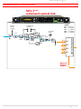
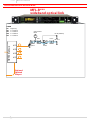
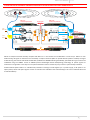
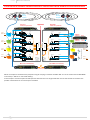
1
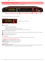
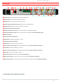
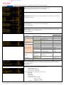
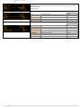
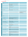
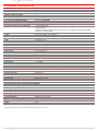
MFLUserManual RF over Fiber System SN: ________________ rev.02 (ref. FW 1.1) Date: 23 April, 2014 Up to 4 ch’s in a single mode fiber Diversity reception antenna remoting IFB transmissions remoting Integrated tunable filters Optical & RF power meter Ethernet conn. for remote control MFLUserManual rev.02 rev.02 MFLUserManual BRIEFDESCRIPTION MFL provides wideband optical link for up to 4 RF channels combined in one single mode fiber thanks to CWDM technology. It is designed to allow for a flexible and modular configuration thanks to a mainboard that can be fitted with up to 4 plug‐in boards that can be chosen any combination of two types: • TX: Laser optical transmitter, (CDWM) plug‐in board • RX: Optical‐receiver plug‐in board Example of some possible configurations: ‐ MFL‐TTTT is a 4 laser transmitters on channel 51/53/55/57 (λ = 1510/1530/1550/1570 nm). ‐ MFL‐RRRR is a 4 optical receiver on channel 51/53/55/57 ‐ MFL‐RRTT has 2 receiver on ch. 51/53 and 2 transmitters ch. 55/57 (it works with MFL‐TTRR) ‐ MFL‐TTRR has 2 transmitter on ch51/53 and 2 receiver on ch. 55/57 (it works with MFL‐RRTT) Mainfeatures: CWDM LASERs to fit many RF channels over a single fiber LOW NOISE DESIGN to allow great coverage when used to remote receiving antennas HIGH INTERFERENCE IMMUNITY thanks to high IIP3 design and a control/compensation of gain EASY TO USE thanks to integrated RF/optical power meter and optical power compensation DIGITALLY TUNABLE FILTERS 25 MHz bandwidth, center frequency tunable over 404‐788 MHz (optional) INTEGRATED FAILSAFE REDUNDANCY: It can route RF through an external filter or to additional receiver (redundancy) to easily implement a failsafe configuration that can switch on a redundant receiver or transmitter if any fault is detected IFB MODE: It can route an IFB high power signal to transmit locally and send IFB carrier over fiber to slave units. When it is working along with a MTK952MS in slave configuration, the fiber loss is automatically recovered and the unit increases the gain so that the transmitter power equals the target level (measured with an power/SWR meter integrated into the MTK952MS) REMOTE MONITOR/CONTROL: thanks to a data link on Ethernet 10/100 Base Tx REDUNDANT AC / DC POWER SUPPLY: ‐ AC: 90V‐264V~, 47‐63 Hz, 2A fused, max 60 Watts ‐ DC: 10‐28Vdc (max 5A), [XLR‐4M] VDC‐pin 4 / GND‐pin 1 / NC‐pin 2 / NC‐pin 3 NOTE: if both AC/DC power are supplied, the device uses only AC power supply RF INPUT/OUTPUT: ‐ 4 N connector female 50Ω with switchable 12V boosting power (only on transmitter modules) ‐ 2 BNC‐F 50Ω each optical transmitter module, failsafe option or external RF filter ‐ 1 BNC‐F 50Ω each optical receiver module, failsafe option OPTICAL INPUT/OUTPUT: 5 connectors SC‐APC type DATA LINK: Ethernet on RJ45 10/100 Base TX MFLUserManual rev.02 SAFETYINSTRUCTION Read this safety instruction and the manual first Follow all instructions and information. Do not lose this manual. Do not use this apparatus under the rain or near the water. Do not install the apparatus near heaters or in hot environments, do not use outside the operating temperature range. Mount the apparatus as indicated in the instruction, do not block side grids for air ventilation ATTENTION: supply the apparatus with a correct mains voltage and with the ground connection. Check the power cord integrity. The power cord must be protected from damage Do not install the apparatus near heaters or in hot environments, do not use outside the operating temperature range. Do not open the apparatus, only qualified service technician are enabled to operate on it. The apparatus needs servicing when it is not properly working or is damaged by liquids, moisture or other objects are fallen inside the apparatus. Use only accessories or replacement parts authorized or specified by the manufacturer. Clean the apparatus only with dry cloths, do not use liquids. The ON/OFF is a double pole circuit breaker, but to ensure the complete disconnection of the apparatus, disconnect the power cord. Report the serial number and the purchasing date in front of the manual. It is needed to have proper replacement parts or accessories from the manufacturer. When replacement parts are needed, use only replacement parts authorized from the manufacturer. Substitution with not authorized parts could result in electric shock, hazards or fire. Keep attention on all the labels with warnings or hazards on the apparatus. Optical Safety!!! Wisycom MFL contains laser diode sources operating at 1460 to 1620 nm. These devices are rated at under IEC 60825‐1:2007 as CLASS 1M LASER PRODUCT Never look into the end of an optical fibre directly or by reflection either with the naked eye or through an optical instrument. Never leave equipment with radiating bare fibres accessible – always cap the connectors. Do not remove equipment covers when operating. Adjustment, maintenance and repair of the equipment should only be carried out by suitably qualified personnel. This product is supplied with angle‐polished connectors and these must not be confused with standard flat, spherical or "super" polished connectors. These connector types are not interchangeable and mating one with the other will damage both the cable and the equipment. The specification of the optical connector is critical to the performance of the complete fibre optic link. System performance can only be guaranteed with fibre optic cables and connectors supplied by Wisycom. rev.02 MFLUserManual FRONTPANELCONTROLANDFUNCTIONS MFL allows an easy and quick configuration using buttons, push knobs and display. A B C D The front panel is functionally divided in the following section: A–LINKSTATUS ❹ Transmitter / Receiver configurations ❺ ❷ ❶ ❸ ❶ Connection status: The first column of LEDs indicate Alarms The ON column indicate if a module is ON The FAILSAFE column indicate if the Failsafe option is enabled STATUS and CONN, showing the LED indications of the Ethernet module on the rear panel ❷ Display (64 x 256 pixels yellow OLED display) ❸ 3 push buttons (membrane). The function of each button (upper, middle and lower) will be readable from the contextual menu on the display. ❹ Warning (YELLOW) and Alarm (RED) light indicator ❺ Push rotary knob. Rotate and push to select. B–LINKDIAGRAM This part shows the block diagram of one complete channel and the BOOSTER supply if enabled from the transmitters C–TEMPERATUREALARMS&CONFIGURATIONLABEL TEMP. ALARM: indicate eventually high temperature on the device. FAN1/FAN2: these LEDs turn on if faults occur to the cooling system. CONFIGURATION LABEL: name and configuration of the device. D‐LOCK&POWER LOCK: it locks the editing of the display. POWER: ON/OFF square powering button turns on/off the MFL. Above the power button, there are two LEDs to indicate the type of power supply. NOTE: If both AC/DC power are supplied, both LEDs turn on but the device uses only AC power supply MFLUserManual rev.02 REARPANEL RX* TX* ❶ ❷❸ ❹ ❺ ❻ ❼ ❽ ❾ ❿ ⓫ ⓬ ⓭ ⓮ ⓯ ⓰ ⓱ ⓲ ⓳ ❶ AC Power Plug AC mains power input, IEC Connector 90‐264 Vac ❷ Product label with Serial Number and Options installed ❸ Ground point To connect the MFL rack frame to ground ❹ DC Power Plug (only with MFL‐DC option) DC power input, 10‐28Vdc, Max 5A ❺ Ethernet socket (RJ45) for connection to a network or computer ❻ Auxiliary optical Input/Output Connector ❼ Optical Input/Output Connectors where the optical signals are divided by wavelength ❽ Optical Input/Output Connector where the optical signals are multiplexed (only with MFL‐DMX option) ❾ Optical safety label ❿ Output N connector female 50Ω (*) ⓫ Orange label: relative laser wavelength = 1570 nm ⓬ Output N connector female 50Ω (*) ⓭ Yellow label: relative laser wavelength = 1550 nm ⓮ Input N connector female 50Ω with switchable 12V boosting power (only on transmitter modules) (*) ⓯ Green label: relative laser wavelength = 1530 nm ⓰ Input N connector female 50Ω with switchable 12V boosting power (only on transmitter modules) (*) ⓱ Blue label: relative laser wavelength = 1510 nm ⓲ BNC‐F connector 50Ω for failsafe option (on receivers modules) (*) ⓳ BNC‐F connector 50Ω to connect the output of an external filter (on transmitters modules) (*) ⓴ BNC‐F connector 50Ω to connect the input of an external filter or for failsafe option (on transmitters modules) (*) * In this example. Other configurations on request. ⓴ rev.02 MFLUserManual SISTEMOVERVIEW The system is composed by a MFL‐BASE (1U rack frame) and some optional/modular boards to build the desired configuration. MFL‐BASE can have up to 4 optical modules that can be either TX or RX (factory installed) to adapt the unit to several configurations. To simplify the usage we give a name of the final configuration that easy identify the CWDM channels and a color code for the RF connectors (N type). We use as default 4 laser wavelength although the CWDM standard can allow to use much more with a 20nm wavelength separation: ‐ Channel 51 short name for wavelength 1510 nm ‐ Channel 53 short name for wavelength 1530 nm ‐ Channel 55 short name for wavelength 1550 nm ‐ Channel 57 short name for wavelength 1570 nm Channel Wavelength Color Identifier 51 Wavelength 1510 nm laser, single mode Blue 53 Wavelength 1530 nm laser, single mode Green Wavelength and Color Coding: 55 Wavelength 1550 nm laser, single mode Yellow 57 Wavelength 1570 nm laser, single mode Orange For example: NAME (i.e.) Ch. 51 Ch. 53 Ch. 55 Ch. 57 ‐ MFL‐TTRR has 2 Tx on ch.51/53and 2 Rx on ch 55/57 MFL‐TTRR T T R R ‐ MFL‐RRTT has 2 Rx on ch.51/53 & and 2 Tx on ch 55/57 MFL‐RRTT R R T T MFL‐TT** T T ‐ ‐ ‐ MFL‐TT** has 2 Tx on ch.51/53 and no module on ch 55/57 MFL‐RR** R R ‐ ‐ ‐ MFL‐RR** has 2 Rx on ch.51/53 and no module on ch 55/57 Following the main code and option that can build up a MFL system: # 1 Code MFL‐BASE Optional 2 3 4 5 6 MFL‐RX MFL‐TX MFL‐DC MFL‐DMX MFL‐BF1 Description WIDEBAND RF OVER FIBER MAINBOARD 19' 1U Rack units , aluminium frame Oled display ‐ Ethernet ‐ failsafe switch ‐ realtime clock AC Powered 230V Optical RX module for MFL (CWDM) Laser TX module for MFL (CWDM) Insulated DC power with battery monitor (10÷28Vdc) Module Mux/Demux for 1:4 CWDM RF filter 25MHz tuning range over 404÷788 MHz ⑤ ⑥ ⑥ * ② ② ② ② ③ ③ ③ ③ ④ ① * The images are purely for information. This represent one of the possible configurations Max 4 modules (between TX and RX) MFLUserManual rev.02 SYSTEMDESCRIPTION:TRANSMITTERMODE MFL-T*** wideband optical link Antenna Booster (+12VDC) External Filter (Failsafe) IN OUT RF Power Meter CWDM CH Frequency #51 = 1510nm #53 = 1530nm #55 = 1550nm #57 = 1570nm 140 MHz RF-IN Failsafe Switch Tunable IFB-IEM Link Laser #51 #53 #55 #57 Optional Splitted Output Optical Multiplexer RX Antenna Gain Link rev.02 MFLUserManual SYSTEMDESCRIPTION:RECEIVERMODE MFL-R*** wideband optical link CWDM CH Frequency #51 = 1510nm #53 = 1530nm #55 = 1550nm #57 = 1570nm Optical Power Meter RF-IN (Failsafe) M Optical Demux Multiplexer Gain #51 #53 #55 #57 Optional Splitted Output Optical 140 MHz Failsafe Switch RF-OUT MFLUserManual rev.02 CONFIGURATIONEXAMPLE:REMOTEDIVERSITYWITHDOUBLEFAILSAFEREDUNDANCY Remote Diversity Reception B Local Diversity Reception MFL-T*T* wideband optical link Antenna Booster (+12VDC) #53 IFB-IEM Link Antenna Booster (+12VDC) Laser External Filter (Failsafe) IN #55 #57 OUT Optical Mux/Demux #51 Optical Power Meter Gain #55 Failsafe Switch RX.51 Mode: ANT RF OUT AT MTK283 matrix combiner #57 option RX Antenna Gain Link Lin RF-OUT F Failsafe Switch Optical Optical Power Meter option 140 MHz 140 MHz #53 RF Power Meter RF-IN RF-IN (Failsafe) M #51 RF-IN (Failsafe) M Gain 140 MHz RF-OUT RX.55 Mode: ANT RF OUT RF Power Meter RX Antenna Gain Link Lin Optical Mux/Demux OUT Tunable RF IN MFL-R*R* wideband optical link single-mode 140 MHz RF-IN Failsafe Switch TX.55 Mode: ANT B External Filter (Failsafe) IN TX.51 Mode: ANT RF IN A A MRK960 wideband receiver Tunable CWDM CH Frequency #51 = 1510nm #53 = 1530nm #55 = 1550nm #57 = 1570nm IFB-IEM Link Laser MFL-T*T* (redundant link) splitted output splitted output Optical Failsafe Switch CWDM CH Frequency #51 = 1510nm #53 = 1530nm #55 = 1550nm #57 = 1570nm MFL-R*R* (redundant link) Example of a redundancy link (1-fault tolerance) with automatic failsafe switches Above an example of remote diversity reception with MFL‐T*T* in the remote site and MFL‐R*R* in local site (i.e. OB van or main studio facility). RF signal on remote site are received by a couple of antennas (MFL can provide booster power if needed). The signal is filtered using the internal wide‐band tunable filter (25 MHz over 400‐800 switching‐bandwidth), optimized with a gain control and modulated using the LASERS. Thanks to CWDM (Coarse Wavelength Division Multiplexing) technology all optical signals are combined in a single fiber. In this way we can optimize the fiber but also it makes very easy to have a system totally redundant. Failsafe switches (both in MFL‐T*T* and MFL‐R*R*) allow RF re‐routing if a fault happens (i.e. no power supply, no RF power or no optical power). All RF and optical signals are then re‐routed on the redundant links automatically (in this case a redundant fiber and 2 redundant MFLs)! rev.02 MFLUserManual CONFIGURATIONEXAMPLE:REMOTEDIVERSITYANDIFBAREAWITHDOUBLEFAILSAFEREDUNDANCY A Remote Diversity Reception B Local Diversity Reception A B single-mode optical fiber MFL-TTTT wideband optical link MFL-RRRR wideband optical link OUT RF Power Meter RF IN Failsafe Switch IFB-IEM Link 140 MHz RX.51 Mode: ANT RF-OUT OUT RF-IN (Failsafe) RF OUT M RX Antenna Link Gain Tunable Laser External Filter (Failsafe) Antenna Booster (+12VDC) IN #51 #53 OUT RF Power Meter #55 #57 140 MHz RF-IN RX Antenna Gain Link Failsafe Switch Mux/Demux Optical Multiplexer Gain Optical Mux/Demux Multiplexer Failsafe Switch #51 #53 140 MHz Optical Power Meter #55 RF-OUT Failsafe Switch Optical RX.53 Mode: ANT RF-IN (Failsafe) M Gain #57 140 MHz RF-OUT RF OUT Failsafe Switch Optical Antenna Booster (+12VDC) Laser IN option IFB-IEM Link option Tunable External Filter (Failsafe) OUT RF Power Meter 140 MHz splitted output splitted output Optical Power Meter RF-IN (Failsafe) M RF-IN RF IN RX Antenna Gain Link Failsafe Switch Gain Tunable IFB-IEM Link Laser CWDM CH Frequency #51 = 1510nm #53 = 1530nm #55 = 1550nm #57 = 1570nm CWDM CH Frequency #51 = 1510nm #53 = 1530nm #55 = 1550nm #57 = 1570nm MRK960 wideband receiver B Optical RF OUT Remote Intercom Reception Optical Power Meter RF Power Meter RF-IN RF IN MAT283 matrix combiner A TX.57 Mode: ANT Optical 140 MHz RF-OUT Failsafe Switch Local Intercom Reception TX.55 Mode: ANT Failsafe Switch Laser 140 MHz RF IN RF OUT IN IFB-IEM Link Gain External Filter (Failsafe) Antenna Booster (+12VDC) B TX.53 Mode: ANT RF-IN (Failsafe) M RX Antenna Gain Link Tunable Optical Power Meter 140 MHz RF-IN A IN TX.51 Mode: ANT External Filter (Failsafe) Antenna Booster (+12VDC) RX.55 Mode: ANT RX.57 Mode: ANT MFL-TTTT (redundant link) MFL-RRRR (redundant link) Example of a redundancy link (1-fault tolerance) with automatic failsafe switches Above an example of remote diversity reception using all of 4 plug‐in modules available: MFL‐TTTT in the remote site and MFL‐RRRR in local site (i.e. OB van or main studio facility). In this example a remote reception for Microphones and Intercoms: one single mode fiber carries 4 RF channels and another one provides 1‐fault tolerance on all active parts if needed! MFLUserManual rev.02 CONFIGURATIONEXAMPLE:REMOTEDIVERSITYANDIFBAREA A Remote Diversity Reception B Local Diversity Reception A B single-mode MFL-TTRR wideband optical link Antenna Booster (+12VDC) External Filter (Failsafe) OUT RF Power Meter Optical Power Meter 140 MHz A RX Antenna Gain Link Failsafe Switch Gain Antenna Booster (+12VDC) RF-OUT Optical IN A MAT283 matrix combiner OUT Optical Power Meter RF Power Meter 140 MHz RF-IN (Failsafe) M RF-IN RX Antenna Gain Link Laser #51 Optical Power Meter RF-IN (Failsafe) RF OUT #55 #57 140 MHz RF-OUT Gain Mux/Demux Optical Multiplexer Tunable Mux/Demux Optical Multiplexer Failsafe Switch Gain #51 140 MHz RF-OUT IN RF Power Meter 140 MHz Gain RF-IN RX Antenna Link option option Optical splitted output splitted output MTK952 TX2 Gain Optical CWDM CH Frequency #51 = 1510nm #53 = 1530nm #55 = 1550nm #57 = 1570nm CWDM CH Frequency #51 = 1510nm #53 = 1530nm #55 = 1550nm #57 = 1570nm Remote IFB/IEM + MTK952 SLAVE wideband DDS transmitter Single-frequency operation IN RF IN RF Power Meter 140 MHz 140 MHz RF-OUT Antenna Booster (+12VDC) External Filter (Failsafe) RF-IN (Failsafe) RF OUT Gain RF-IN RX Antenna Link Failsafe Switch Tunable Laser TX.55 Mode: IFB IFB-IEM Link Laser OUT Optical Power Meter RF IN MTK952 TX1 Failsafe Switch Tunable MTK952 TX1 MRK960 wideband receiver Antenna Booster (+12VDC) External Filter (Failsafe) OUT #57 RF OUT B Failsafe Switch Optical #53 #55 RX.53 Mode: ANT B RF OUT External Filter (Failsafe) RF IN #53 RX.57 Mode: IFB RX.51 Mode: ANT Failsafe Switch Laser IFB-IEM Link RX.55 Mode: IFB 140 MHz Tunable IFB-IEM Link TX.53 Mode: ANT RF-IN (Failsafe) M RF-IN TX.51 Mode: ANT IN RF IN MFL-RRTT wideband optical link MTK952 TX2 TX.57 Mode: IFB IFB-IEM Link Local IFB/IEM single-frequency IFB area + MTK952 MASTER wideband DDS transmitter Single-frequency operation Above an example of remote diversity reception using all of 4 plug‐in modules available: - MFL‐RRTT in the remote site and MFL‐TTRR in local site (i.e. OB van or main studio facility). The remote antenna reception mode is similar to the one already described before. Again the tunable filter and variable gain allow a complete power control, in this way fiber always works at best condition without any risk of saturation! All RF and optical power can be remotely monitored through Ethernet but also can be recorded with the real ‐time clock for later check! Using MAT283 matrix combiner the remote and the local area can be integrate in a very safe way: areas which are not needed or noisy can be disabled in real time! Simply setting up the MFL mode from “ANT” (antenna) to “IFB”, it commutes on an internal RF path designed to best modulate a reference IFB signals. On local site a MTK952MS in master configuration generates an IFB signal and a reference out that feeds the optical transmitter (in mode “IFB”). On the remote site, the reference signal is received and amplified through a MTK952MS in slave configuration: This way we can create a single‐frequency IFB area! The system is able to compensate optical and RF power: - MFL monitors (through an optical power meter) and compensates automatically the loss of fiber! - MTK952 monitors the transmitted level (with and internal power/SWR meter) to reach desired output power! rev.02 MFLUserManual OLEDDISPLAY MFLInfoscreen Switch on the MFL and by pushing the rotary knob (at the right of the display) all the basic information are displayed: ❶ Product name ❷ Serial number ❸ Class and Hardware version ❹ Firmware version ❺ Application Firmware version Push the rotary knob to enter the Main screen Mainscreen In the left top side of the main screen there is the “NAME” of the MFL that is settable in the Main menu. At the right of "NAME", date and time are displayed. The first number (1 to 4) identify the link (same reference on back‐side connectors). TX or Rx if that link has a laser transmitter or a receiver, respectively. The last number after the dot, 51/53/55/57 refers to the CWDM link frequency: 1510/1530/1550/1570nm. ON/OFF status of specific link There are 2 possible modes: ‐ ANT as remote antenna link ‐ IFB as remote intercom link optimized on a 0dBm reference input Antenna Booster (+12VDC) External Filter (Failsafe) IN OUT RF Power Meter CWDM CH Frequency #51 = 1510nm #53 = 1530nm #55 = 1550nm #57 = 1570nm 140 MHz RF-IN RX Antenna Gain Link Failsafe Switch Tunable IFB-IEM Link Laser #51 #53 #55 #57 Optical Multiplexer If the link is a transmitter (i.e. 1 TX.51) then there are 4 possible configurations: 1. 150‐840 to select a fixed 150‐840 MHz band‐pass filter 2. 470‐840 to select a fixed 470‐840 MHz band‐pass filter 3. BPF to select the tunable filter, the number within brackets shows the center frequency on a 25 MHz bandwidth 4. EXTERN to select an external filter (between IN and OUT BNC connectors) , or Pushing on lower right button the last column shows: ‐ CUR/PWR show the RF/optical power in reception or the laser current in TX module ‐ RF LEV shows the value of the RF power level ‐ “GAIN” that is the relative gain of the link. Here it is possible to change the gain in the operating range. NOTE: unless you have special needs we recommend to keep GAIN to 0 dB and enable the optical power correction on the receiver side, since this is already optimized for most applications! MFLUserManual rev.02 MenuTree Name Optical connectors CONN# 1 / 2 / 3 / 4 / 5 DISPLAY brightness 1÷15 DISPLAY timeout 5÷120 IP Address Serial FW ver FW Boot ver App FW ver Main Board Temperatures Main Temperature of the TX Supply source External DC Info Main RAW (+12v6) Supply diagnostic Main Digital (+5v) Main Analog (+5v) Laser supply (‐5v) History alarm list Alarms Current alarm list Date/time Life time Ext. DC alarm threshold Factory preset OFF / 10.0÷28.0 V rev.02 MFLUserManual ON/OFF Mode IFB / ANT Filter BP filter center freq. 150‐840 / 470‐840 / BPF / EXTERN Central freq. 404÷788 MHz (Bandwidth 25MHz) With IFB Mode: ‐23.5 ÷ 8.0 dB Gain With ANT Mode & filter: ‐ BPF: ‐28.0 ÷ 3.5 dB ‐ EXTERN: ‐22.0 ÷ 9.5 dB ‐ 150‐840: ‐20.0 ÷ 11.5 dB ‐ 470‐840: ‐20.0 ÷ 11.5 dB TX LINK Menu Booster enabled / disabled Booster supply Failsafe enabled / disabled Ext filter att. 0.0 ÷ 6.0 dB ID Serial BP filter App FW ver Center freq range Filter bandwidth ID Serial Current limits Optical power Transmitter param Temperature Offset gain Wavelength Only with ANT Mode Life time Only with ANT Mode & BPF filter. BPF settable only with the option MFL‐BF1 Status RX LINK Menu MFLUserManual rev.02 Status ON/OFF Mode IFB / ANT Gain ‐13.5 ÷ 18.0 dB Failsafe enabled / disabled Optical power Optical pwr. corr. ON / OFF ID Serial Opt rx pwr limits Receiver param Temperature Offset gain Wavelength Life time rev.02 MFLUserManual Mainmenu From the Main screen, pushing the upper right button, it’s possible to enter on the main menu options: Name: to change the name of the MFL shown in the Main screen. 12 alphanumeric characters (A‐Z, a‐z, 0‐9, case‐sensitive) Optical connectors: parameter that show the configuration and the optical attenuation of the 5 optical connectors DISPLAY brightness: To set the brightness of the OLED display. 0÷15 step 1 (default 0) DISPLAY timeout: to set the display timeout before decrease the brightness of the OLED display and before returning to Main screen. (default 30 seconds) Info: here it’s possible to enter in the info menu and see the following information: Example IP address of the device IP address 192.168.1.10.240 The serial number composed by 1 letter + 7 numbers Serial T3427043 Firmware version FW ver 1.1 Bootloader version FW Boot ver 1.0.d Application version App FW ver 1.9.d Main board temperature Main Board 31°C Temperature Transmitter module temper. x TX.5x 38°C Type of power supply (AC/DC) Supply source AC DC voltage supply External DC 12.40V Main RAW (+12v6) Main RAW voltage measured 12.82V Supply diagnostic Main Digital (+5v) Main Digital voltage measured 5.20V Main Analog Main Analog voltage measured 5.21V (+5v) Laser supply (‐5v) Laser voltage supply ‐5.21V Alarms Date/time Life time History alarm list (HIST) Date and time Life time of the device Number and type of alarms for the general apparatus and for each module 0 Alarms memory ‐ 28/04/14 14:02 3d ‐ 00h – 01m Ext. DC alarm threshold: This menu item allows to enable and set a threshold for the alarm of low external DC power supply. If it is enabled, the threshold can be set from 10.0V to 28.0V with 0.1V step. (default OFF) Factory preset: with this option it’s possible to reset the MFL to make the factory preset. The main parameters that are resetted by this function are: ‐ Display brightness: 0 ‐ Display timeout: 30 seconds ‐ Ext. DC alarm threshold: OFF The link parameters that are reset by this function are: ‐ Status: ON ‐ Mode: ANT ‐ Gain: 0.0dB ‐ Failsafe: disabled ‐ For TX Links: ‐ Filter: 470‐840 ‐ Booster: disable ‐ Ext filter att.: 2.0dB ‐ For RX Links: ‐ Optical pwr. corr.: ON Current alarm list (ENTER) MFLUserManual rev.02 TXLinkmenu From the Main screen, pushing the rotary knob, it’s possible to enter on the selection screen and then, pushing the upper right button on the desiderate transmitter module, it’s possible to enter on the TX Link menu: Status: status of the transmitter (default ON) Mode: working mode selection: ‐ ANT for remote antenna reception ‐ IFB for remote intercom for iso‐frequency areas NOTE: set the transmitter module and the receiver module with the same working mode (as in the third configuration example) (default ANT mode) Filter: Type of RF filter (only for ANT mode) There are 4 possible configurations: ‐ 150‐840: to have a fixed 150‐840 MHz band‐pass filter ‐ 470‐840: to have a fixed 470‐840 MHz band‐pass filter ‐ BPF: tunable Band‐Pass Filter (only with MFL‐BF1 option) ‐ EXTERN: to connect an external RF filter between IN and OUT BNC connectors (default 470‐840) BP filter center freq: allows to set the center frequency of the 25MHz Band Pass filter. It is selectable only if the optional tunable BP filter (opt: MFL‐BF1) is mounted and the Filter selection is set to the tunable Band‐Pass Filter (BPF). Allowed range: center frequency 404÷788, 1MHz step. Gain: Settable gain with step of 0.5dB. With IFB Mode: ‐23.5 ÷ 8.0 dB (typ.) With ANT Mode & filter: ‐ 150‐840: ‐20.0 ÷ 11.5 dB (typ.) ‐ 470‐840: ‐20.0 ÷ 11.5 dB (typ.) ‐ BPF: ‐28.0 ÷ 3.5 dB (typ.) ‐ EXTERN: ‐22.0 ÷ 9.5 dB (typ.) (default 0.0dB) Booster: To enable or disable the 12V boosting power (only for TX module in ANT mode) (default disabled) Booster supply: shows the voltage and current on the output connector, supplied with the booster option (only for TX module in ANT mode & Booster set to enabled) Failsafe: To enable or disable the Failsafe option (default disabled) rev.02 MFLUserManual Ext filter att.: Attenuation of the external filter, that can be set by user from 0.0 to 6.0dB with step of 0.5dB. (default 2.0dB) BF filter: here it’s possible to see all the Band‐Pass filter information: Example ID ID of the RF filter TBF01 Serial Serial number of the RF filter T1541322 App FW ver. Application firmware version of the RF filter 1.0 Center freq. range Center frequency range of the RF filter 404 ‐ 788 MHz Filter bandwidth Filter bandwidth 25 MHz Transmitter param: here it’s possible to see all the transmitter parameters: ID Serial Current limits Optical power Temperature Offset gain Wavelength Life time ID of the transmitter Serial number of the transmitter Laser current working range Transmission optical power Working temperature Offset gain correction Optical wavelength Life time of the device Example OTM001 T1845210 10.0mA ‐ 50.0mA 2.0 mW 39°C 0.0 dB 1510nm 3 d ‐ 00 h ‐ 49 m MFLUserManual rev.02 RXLinkmenu From the Main screen, pushing the rotary knob, it’s possible to enter on the selection screen and then, pushing the upper right button on the desiderate receiver module, it’s possible to enter on the RX Link menu: Status: status of the transmitter (default ON) Mode: working mode selection: ‐ ANT for remote antenna reception ‐ IFB for remote intercom in isofrequency areas applications (default ANT mode) Gain: Settable gain from ‐13.5 to 18.0dB with step of 0.5dB. (typ.) (default 0.0dB) Failsafe: To enable or disable the Failsafe option (default disabled) Optical power: This parameter show the received optical power Optical pwr. corr.: (optical power correction) this option can be enabled to ensure that, in case in changes of optical power, the overall gain of the system remains unchanged (to keep the gain in the RF output at 0dB). (default ON) Receiver param: here it’s possible to see all the receiver parameters: ID ID of the receiver Serial Serial number of the receiver Opt rx pwr limits Optical power working limits Temperature Working temperature Offset gain Offset gain of the module Wavelength Optical wavelength Life time Life time of the device Example ORM001 T1841930 0.3mW – 3.0mW NA 0.0 dB 1550nm 3 d ‐ 00 h ‐ 49 m rev.02 MFLUserManual AlarmList When an alarm occurs, the MFL can show one or more of the following warnings: A. Show a message on the display B. Turn on the yellow or red alarm led C. Light up an auxiliary LED (in some cases) D. Insert the alarm on the current alarm list and in the “history” alarm list (in MAIN>Info>Alarms menu) Current alarm list: pushing the rotary knob, it’s possible to enter in the current alarm list where are displayed the number and type of current alarms in the general apparatus or in each module History alarm list: pushing the upper right button, it’s possible to enter in the “history” alarm list where the alarm previously stored is displayed The informations that are displayed in the history alarm screen are: 1 2 3 4 5 6 7 1 Progressive number of the alarm 2 Alarm CODE 3 Type of alarm: ‐ open: when the alarm started ‐ close: when the alarm stopped 4 Alarm description 5 Where the alarm occurred 6 When the alarm occurred 7 Other informations NOTE: with the center right button it’s possible to delete all alarms in the history alarm list (DEL ALL) MFLUserManual rev.02 The alarm can be related to a specific transmitter/receiver or general. Shown below the complete alarms list: GENERAL ALARM Name Message on display (A) Auxiliary LED (C) Alarm LED (B) Alarm list (D) E2_INVALID 0x06 Invalid int memory FIXED RED ‐ ‐ E2_INVALID_COPY1 0x80 Calibration data copy #1 invalid FIXED YELLOW ‐ Cal data copy1 invalid E2_INVALID_COPY2 0x81 Calibration data copy #2 invalid FIXED YELLOW ‐ Cal data copy2 invalid E2_CRC_DIFF 0x07 Calibration data copies differ FIXED RED ‐ ‐ E2_ERROR_UPDATE_CRC 0x08 Error updating calibration copy crc FIXED RED ‐ cal copy crc update error HW_INIT_FAILED 0x09 System boot failed. FIXED RED ‐ ‐ NO_LINKS 0x0A No links declared in calibration memory FIXED RED ‐ ‐ NO_LINKS_FOUND 0x0B No links hw detected FIXED RED ‐ ‐ PWR_SUPPLY 0x0C Power supplies failure FIXED YELLOW ‐ power supplies failure TEMP 0x04 Internal high temperatur ‐ "TEMP. ALARM" high temperature RED SLOWLY BLINKING I2C0 0x0D Communication error on I2C bus #0 FIXED RED ‐ I2C bus #0 I2C1 0x0E Communication error on I2C bus #1 FIXED RED ‐ I2C bus #1 FAN1 0x02 Fan #1 does't work properly YELLOW SLOWLY BLINKING FAN 1 fan #1 FAN2 0x03 Fan #2 does't work properly YELLOW SLOWLY BLINKING FAN 2 fan #2 0x0F Temperature sensor doesn't communicate RED SLOWLY BLINKING ‐ temperature sensor comm. LOW_BATT 0x10 Backup battery low RED SLOWLY BLINKING ‐ backup battery low LINK__NOT_FOUND LINK__NOT_CONSISTENT LINK__LASER_E2_INVALID LINK__LASER_E2_INVALID_ COPY1 LINK__LASER_E2_INVALID_ COPY2 LINK__LASER_E2_CRC_DIFF LINK__LASER_E2_ERROR_U PDATE_CRC LINK__RF_FIL_NOT_FOUND LINK__RF_FIL_E2_INVALID LINK__RF_E2_INVALID_COP Y1 LINK__RF_E2_INVALID_COP Y2 LINK__RF_FIL_E2_UNCAL LINK__RF_FIL_E2_DIFF LINK__ON_OFF 0x0B 0x11 0x12 HW not found Link type doesn't match Laser calibration data invalid * * * HW not found Link type match Laser cal data invalid 0x13 Laser calibration data copy 1 invalid FIXED RED FIXED RED FIXED RED FIXED RED * Laser cal copy1 invalid FIXED RED * Laser cal copy2 invalid FIXED RED FIXED RED * Laser cal crc mismatch * Laser cal crc update FIXED RED FIXED RED FIXED RED * * RF filter not found RF filter invalid E2 * RF fil cal copy #1 inval. FIXED RED * RF fil cal copy #2 inval. FIXED RED FIXED RED FIXED RED YELLOW SLOWLY BLINKING RF filter not calibrated RF fil cal copies differ On/Off procedure failure FIXED YELLOW * * * FAILSAFE FAST BLINKING + * FAILSAFE FAST BLINKING + * BOOSTER FAST BLINKING + * * RED SLOWLY BLINKING * temperature sensor comm. TEMP_SENS LINK ALARM Code 0x14 Laser calibration data copy 2 invalid 0x15 Laser calibration crc mismatch 0x16 Laser calibration crc update error 0x17 0x18 RF filter not found RF filter invalid calibration data 0x19 RF filter calibration data copy #1 invalid 0x1A RF filter calibration data copy #2 invalid 0x1B 0x1C 0x20 RF filter not calibrated RF filter calibration copies differ On/Off procedure failure LINK__FAILSAFE_RX 0x1D ALARM: optical power lost LINK__FAILSAFE_TX 0x1D ALARM: laser current out of range LINK__BOOSTER 0x1E ATTENTION: booster over current LINK__LASER_EOL 0x1F LINK__TEMP_SENS 0x0F ATTENTION: laser life terminating Temperature sensor doesn't communicate YELLOW SLOWLY BLINKING YELLOW SLOWLY BLINKING failsafe active failsafe active booster overcurrent laser life terminating * In the "ALARM" column in the front panel, appears a blinking red LED in correspondence at the link on which the alarm is being rev.02 MFLUserManual Troubleshooting LINK ALARM GENERAL ALARM Alarms Troubleshooting E2_INVALID E2_INVALID_COPY1 Has not been validated the CRC of the copy #1 of the data of calibration of E2 memory E2_INVALID_COPY2 Has not been validated the CRC of the copy #2 of the data of calibration of E2 memory E2_CRC_DIFF The two copies of the data in the internal E2 memory, have a valid CRC but different from each other E2_ERROR_UPDATE_CRC There was an error while updating the CRC of the calibration data in the internal E2 memory HW_INIT_FAILED There was an error during the initialization phase of the machine NO_LINKS In the internal E2 memory are not declared the Links (Rx or Tx) to manage NO_LINKS_FOUND The Links to manage are declared, but physically it was not possible to communicate with any module, so it is assumed that they haven't been installed PWR_SUPPLY Abnormalities were noted in the power supply of the machine. ‐ check if the two fans work properly (check alarms code 0x02 or 0x03 on the alarm list) ‐ switch off the MFL for cooling and check the location temperature ‐ clean the ventilation grids TEMP One of the temperature sensors measures a temperature > 60°C I2C0 Error on I2C0 bus I2C1 Error on I2C1 bus FAN1 The fan on the left (#1) doesn’t turn ‐ switch off and switch on the MFL FAN2 The fan on the right (#2) doesn’t turn ‐ switch off and switch on the MFL TEMP_SENS Communication error with the temperature sensor of the main board LOW_BATT This message informs that the backup battery is running low LINK__NOT_FOUND I‐th link not found. The error is detected in the initialization phase when attempting to communicate with the E2 memory on the module to establish if the module is present or not. Note: The link is not considered valid and therefore will not be present among those available LINK__NOT_CONSISTENT I‐th link of type different from that stated in the E2 memory. Note: The link is not considered valid and therefore will not be usable LINK__LASER_E2_INVALID The I‐th link doesn't have a valid calibration memory (none of CRC of the two copies is correct). Note: The link is not considered valid and therefore will not be present among those available LINK__LASER_E2_INVALID_COPY1 The copy #1 of the I‐th link is not valid LINK__LASER_E2_INVALID_COPY2 The copy #2 of the I‐th link is not valid LINK__LASER_E2_CRC_DIFF The CRC of the calibration data of the laser module are valid but different from each other. Note: The link is not considered valid and therefore will not be present among those available LINK__LASER_E2_ERROR_UPDATE_CRC There was an error while updating the CRC of the calibration data of the i‐th laser module LINK__RF_FIL_NOT_FOUND Is declared the presence of the internal RF filter, but is failed the communication. Note: The filter is considered not present, therefore the BPF filter is not present in the items of the transmitters menu (the other filters are available) LINK__RF_FIL_E2_INVALID The internal RF filter has no valid calibration data Note: The filter is considered not present, therefore the BPF filter is not present in the items of the transmitters menu (the other filters are available) LINK__RF_E2_INVALID_COPY1 The copy #1 of the calibration data of the RF filter is not valid LINK__RF_E2_INVALID_COPY2 The copy #2 of the calibration data of the RF filter is not valid LINK__RF_FIL_E2_UNCAL The two copies of the internal RF filter are valid and the CRC equal to each other but there are no valid calibration data. Note: The filter is considered not present, therefore the BPF filter is not present in the items of the transmitters menu (the other filters are available) LINK__RF_FIL_E2_DIFF The two copies of the internal RF filter are valid but the CRC are different from each other Note: The filter is considered not present, therefore the BPF filter is not present in the items of the transmitters menu (the other filters are available) Alarm description None of the two calibration copies of the internal E2 memory is valid MFLUserManual rev.02 LINK__ON_OFF There was an error in the phase of power ON/OFF of a link LINK__FAILSAFE_RX This alarm appear when the Failsafe is activated in a receiver and the optical signal is lost LINK__FAILSAFE_TX This alarm appear when the Failsafe is activated in a transmitter and the laser current goes out of range (the TX module doesn't work properly) LINK__BOOSTER It was detected a malfunction in the power of the booster LINK__LASER_EOL The laser has terminated its life time LINK__TEMP_SENS It was detected a communication problem with the temperature sensor of the laser module If a problem not listed in the above table occurs or if the problem cannot solved with the proposed troubleshooting, please contact support service at [email protected] or [email protected]. rev.02 MFLUserManual TECHNICALSPECIFICATION Mainframe RF to Optical modules (TX module) Optical to RF modules (RX module) Maximum number of modules RF to fiber link working modes Rear optical connectors Internal optical CWDM MUX/DEMUX : : : : : : 1 to 4 1 to 4 4 2 (“ANT” mode or “IFB” mode) 5 SC/APC, other type on request 2 max (option MFL‐DMX) Typical application Frequency ranges (front panel selectable) : : External filter loss compensation TX Gain Input IP3 Noise figure SFDR RF input connector Antenna booster supply External filter connectors : : : : : : : : RX antenna remoting ‐ 140 to 840 MHz (flat) ‐ 470 to 840 MHz ‐ 25MHz BW tunable band‐pass filter (opt*) (center freq. in 1MHz step, from 404 to 788 MHz) ‐ External user band‐pass filter 0 to 6 dB 0dB (user adjustable +6 to ‐20dB typ.) > 16 dBm typ. < 20dB typ. (*) > 116 dB/Hz 2/3 typ. N female 50 Ω 12Vdc 200mA max BNC female 50 Ω : : : : 0dB (user adjustable ± 14dB typ.) yes, standard option N female 50 Ω BNC female 50 Ω : : : : : “IFB” signal remoting (isofrequency systems) 140 to 840 MHz ‐ 6 to 10 dBm from ‐3dBm to + 10dBm N female 50 Ω : : : : 0 dBm (user adjustable +6 to ‐20dB typ.) yes, standard option N female 50 Ω BNC female 50 Ω “ANT” mode RF TX characteristics “ANT” mode RF RX characteristics RX Gain Failsafe option RF output connector Failsafe connector “IFB” mode RF TX characteristics Typical application Frequency range RF input level RF input level for 0dBm out (@ 0dB gain) RF input connector “IFB” mode RF RX characteristics RX output level Failsafe option RF output connector Failsafe connector Optical TX module (option MFL‐TX module OTB001) Optical power Wavelengths Laser : : : 3dBm (6dBm optional) 1511 or 1531 or 1551 or 1571 nm low noise, low distortion DFB laser Optical RX module (option MFL‐RX module ORB001) Input optical power range Wavelengths : : ‐5 dBm to 5 dBm 1490 to 1610 nm : : : ‐20 to +55 °C 90 to 240 Vac, 60VA max 10‐28Vdc 3A frame floating : : 19”/1U, 430x44x370mm (Width x Height x Depth) 4,5 kg Temperature Operating temperature Powering AC mains DC (option MFL‐DC) Dimensions and weight Dimensions Weight (*) Measured with “Ant” mode and 0 dB gain (standard “factory preset”) at 25 °C MFLUserManual rev.02 rev.02 MFLUserManual ENVIRONMENTAL INFORMATION Applicable in the European Union and other European countries with separate collection systems Disposal of Old Electrical & Electronic Equipment (2002/96/EC) This symbol indicates that this products shall not be treated as household waste. Instead it shall be handed over to the appropriate collection point for the recycling of electrical and electronic equipment. The recycling of material will help to conserve natural resources. ITALY ONLY Obblighi di informazione agli utilizzatori ai sensi dell’art. 13 del Decreto Legislativo 25 luglio 2005, n. 151 “Attuazione delle Direttive 2002/95/CE, 2002/96/CE e 2003/108/CE, relative alla riduzione dell’uso di sostanze pericolose nelle apparecchiature elettriche ed elettroniche, nonché allo smaltimento dei rifiuti” Smaltimento di apparecchiature elettriche ed elettroniche di tipo professionale Il simbolo del cassonetto barrato riportato sull’apparecchiatura o sulla sua confezione indica che il prodotto alla fine della propria vita utile deve essere raccolto separatamente dagli altri rifiuti. La raccolta differenziata della presente apparecchiatura giunta a fine vita è organizzata e gestita dal produttore. L’utente che vorrà disfarsi della presente apparecchiatura dovrà quindi contattare il produttore e seguire il sistema che questo ha adottato per consentire la raccolta separata dell’apparecchiatura giunta a fine vita. L’adeguata raccolta differenziata per l’avvio successivo dell’apparecchiatura dismessa al riciclaggio, al trattamento e allo smaltimento ambientalmente compatibile contribuisce ad evitare possibili effetti negativi sull’ambiente e sulla salute e favorisce il reimpiego e/o riciclo dei materiali di cui è composta l’apparecchiatura. Lo smaltimento abusivo del prodotto da parte del detentore comporta l’applicazione delle sanzioni am‐ ministrative previste dalla normativa vigente. Iscrizione al Registro A.E.E. n. IT09100000006319 MFLUserManual rev.02 Wireless System Communications Via Spin 156 I‐36060 Romano d’Ezzelino Italy Tel. +39 ‐0424 ‐382605 Fax +39 ‐ 0424 ‐ 382733 www.wisycom.com e‐mail: [email protected]