1
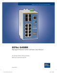
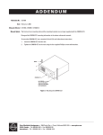
Nuclear Sensors & Process Instrumentation
EOTec MX Multiplexer System
Bi-Directional Control & Communications User Manual
Original Instructions
UE-24-12-mxmp manual.indd 1
6/4/12 6:09 PM
EOTec MX Multiplexer System User Manual
2
UE-24-12-mxmp manual.indd 2
6/4/12 6:09 PM
Nuclear Sensors & Process Instrumentation
Table of Contents
Standards & Safety . . . . . . . . . . . . . . . . . . . . . . . . . . . . . . . . . . . . . . . . . . . . . . . . . . . . . . . . . . . . . . . . . . . . . . . . . . . . . . . . . . . . . . . 4
1.
Introduction . . . . . . . . . . . . . . . . . . . . . . . . . . . . . . . . . . . . . . . . . . . . . . . . . . . . . . . . . . . . . . . . . . . . . . . . . . . . . . . . . . . . . . . . 6
1.1. EOTec MX Multiplexer Modular Solution . . . . . . . . . . . . . . . . . . . . . . . . . . . . . . . . . . . . . . . . . . . . . . . . . . . . . . . . . . . . . 6
2.
EOTec MX Multiplexer Hardware . . . . . . . . . . . . . . . . . . . . . . . . . . . . . . . . . . . . . . . . . . . . . . . . . . . . . . . . . . . . . . . . . . . . . . . 8
2.1. MX Base: Products Designed for Industrial Applications . . . . . . . . . . . . . . . . . . . . . . . . . . . . . . . . . . . . . . . . . . . . . . . . . 8
2.1.1. MX Base Operational Setting . . . . . . . . . . . . . . . . . . . . . . . . . . . . . . . . . . . . . . . . . . . . . . . . . . . . . . . . . . . . . . . . . 10
2.2. Analog Data Links: Products Designed for Flexibility . . . . . . . . . . . . . . . . . . . . . . . . . . . . . . . . . . . . . . . . . . . . . . . . . . . 11
2.2.1. The 4-20mA Process Loop – Input . . . . . . . . . . . . . . . . . . . . . . . . . . . . . . . . . . . . . . . . . . . . . . . . . . . . . . . . . . . . . 11
2.2.2. The 4-20mA Process Loop – Output . . . . . . . . . . . . . . . . . . . . . . . . . . . . . . . . . . . . . . . . . . . . . . . . . . . . . . . . . . . . 13
2.2.3. The 0-10Vdc Process Management – Input . . . . . . . . . . . . . . . . . . . . . . . . . . . . . . . . . . . . . . . . . . . . . . . . . . . . . . 15
2.2.4. The 0-10Vdc Process Management – Output . . . . . . . . . . . . . . . . . . . . . . . . . . . . . . . . . . . . . . . . . . . . . . . . . . . . 17
2.2.5. Analog Data Link Operational Setting . . . . . . . . . . . . . . . . . . . . . . . . . . . . . . . . . . . . . . . . . . . . . . . . . . . . . . . . . 20
2.2.6. Current/Voltage Conversions Using Analog Data Links . . . . . . . . . . . . . . . . . . . . . . . . . . . . . . . . . . . . . . . . . . . . 21
2.3. Digital Data Links: Products Designed for Reliability . . . . . . . . . . . . . . . . . . . . . . . . . . . . . . . . . . . . . . . . . . . . . . . . . . . 22
2.3.1. The Contact Closure – Input . . . . . . . . . . . . . . . . . . . . . . . . . . . . . . . . . . . . . . . . . . . . . . . . . . . . . . . . . . . . . . . . . . 22
2.3.2. The Contact Closure – Output . . . . . . . . . . . . . . . . . . . . . . . . . . . . . . . . . . . . . . . . . . . . . . . . . . . . . . . . . . . . . . . . 24
2.3.3. Digital Data Link Operational Setting . . . . . . . . . . . . . . . . . . . . . . . . . . . . . . . . . . . . . . . . . . . . . . . . . . . . . . . . . . 27
2.4. Communication Data Links: Products Designed for Simplicity . . . . . . . . . . . . . . . . . . . . . . . . . . . . . . . . . . . . . . . . . . . . 28
2.4.1. RS232/485 Communication – Bidirectional . . . . . . . . . . . . . . . . . . . . . . . . . . . . . . . . . . . . . . . . . . . . . . . . . . . . . . 28
2.4.2. RS232/485 Link Operational Setting . . . . . . . . . . . . . . . . . . . . . . . . . . . . . . . . . . . . . . . . . . . . . . . . . . . . . . . . . . . 31
3.
Installation and Removal of Multiplexer Equipment . . . . . . . . . . . . . . . . . . . . . . . . . . . . . . . . . . . . . . . . . . . . . . . . . . . . . . . 33
3.1. Installation . . . . . . . . . . . . . . . . . . . . . . . . . . . . . . . . . . . . . . . . . . . . . . . . . . . . . . . . . . . . . . . . . . . . . . . . . . . . . . . . . . . . . 35
3.2. Removal . . . . . . . . . . . . . . . . . . . . . . . . . . . . . . . . . . . . . . . . . . . . . . . . . . . . . . . . . . . . . . . . . . . . . . . . . . . . . . . . . . . . . . . 36
4.
Troubleshooting . . . . . . . . . . . . . . . . . . . . . . . . . . . . . . . . . . . . . . . . . . . . . . . . . . . . . . . . . . . . . . . . . . . . . . . . . . . . . . . . . . . . 36
4.1. Diagnosing Failure . . . . . . . . . . . . . . . . . . . . . . . . . . . . . . . . . . . . . . . . . . . . . . . . . . . . . . . . . . . . . . . . . . . . . . . . . . . . . . . 33
4.2. Interrupting LED Diagnostics . . . . . . . . . . . . . . . . . . . . . . . . . . . . . . . . . . . . . . . . . . . . . . . . . . . . . . . . . . . . . . . . . . . . . . 37
4.3. Interrupting Remote Relay Diagnostics . . . . . . . . . . . . . . . . . . . . . . . . . . . . . . . . . . . . . . . . . . . . . . . . . . . . . . . . . . . . . . 39
5.
Default Settings . . . . . . . . . . . . . . . . . . . . . . . . . . . . . . . . . . . . . . . . . . . . . . . . . . . . . . . . . . . . . . . . . . . . . . . . . . . . . . . . . . . . 40
6.
Product Dimension . . . . . . . . . . . . . . . . . . . . . . . . . . . . . . . . . . . . . . . . . . . . . . . . . . . . . . . . . . . . . . . . . . . . . . . . . . . . . . . . . . 42
7.
Service . . . . . . . . . . . . . . . . . . . . . . . . . . . . . . . . . . . . . . . . . . . . . . . . . . . . . . . . . . . . . . . . . . . . . . . . . . . . . . . . . . . . . . . . . . . . 43
3
UE-24-12-mxmp manual.indd 3
6/4/12 6:09 PM
EOTec MX Multiplexer System User Manual
Standards & Safety
The EOTec MX Multiplexer Modules from Ultra Electronics have been designed to meet the following standards.
The EOTec MX Multiplexer Series of products all meet the requirements for CE
marking per EN61326-1.
The EOTec MX Multiplexer Series of products are all FM approved for use in
hazardous locations Class I, Division 2, Groups A, B, C & D, T4. Ambient temperature
-40°C To +85°C Max.
FM11ATEX0067X
ATEX Special Conditions of Safe Use
1. Modules shall be installed in an enclosure which maintains an ingress
protection rating of IP54 and meets the enclosure requirements of EN600790 and EN60079-15.
2. The EOTec modules shall be installed in DIN rail with DIN end clamps
mounted on both sides of the module set.
3. The DIN rail must be connected to Protective Earth in order to provide
modules with a Protective Earth connection.
4. Do not disconnect equipment connections or modules when energized.
When operating, do not look directly into the transmit optical port or use
magnification or focusing equipment to view optical output.
IEC 60825-1, Class 1 Laser Product
FDA 21 CFR 1040.10 & 1040.11
CAUTION: Use of controls and/or adjustments or the performance of procedures
other than those specified herein may result in hazardous radiation exposure.
Lightning Danger: Do not work on equipment during periods of lightning activity.
4
UE-24-12-mxmp manual.indd 4
6/4/12 6:09 PM
Nuclear Sensors & Process Instrumentation
Ultra Electronics Protected Technology Policy
ULTRA ELECTRONICS, NSPI protects your investment in with long-term planned technology and our unique Protected
Technology Policy. We will continue to support the specified capabilities of standard ULTRA ELECTRONICS products for at
least five years (twenty years for Industrial Managed Switches). We plan each product improvement and new feature to
be upward compatible with existing designs and installations. Our goals are to make each new software release bring new
power to your ULTRA ELECTRONICS systems and have every existing feature, applications program and data file continue
to work. We protect your investment even further with a liberal five-year trade-in policy. Exchange standard products for
upgraded versions of the same product to take advantage of new features and performance improvements at any time for
five years. A prorated trade-in allowance will be given for your existing equipment. ULTRA ELECTRONICS protects your long
term productivity with state-of-the-art planned technology and continued support.
ULTRA ELECTRONICS Statement of Limited Warranty
ULTRA ELECTRONICS, NSPI, manufacturer of ULTRA ELECTRONICS, NSPI products, warrants to Buyer that products, except
software, manufactured by ULTRA ELECTRONICS, NSPI will be free from defects in material and workmanship. ULTRA
ELECTRONICS, NSPI’s obligation under this warranty will be limited to repairing or replacing, at ULTRA ELECTRONICS,
NSPI’s option, the defective parts within one year of the date of installation, or within 18 months of the date of shipment
from the point of manufacture, whichever is sooner. Products may be returned by Buyer only after permission has been
obtained from ULTRA ELECTRONICS, NSPI. Buyer will prepay all freight charges to return any products to the repair facility
designated by ULTRA ELECTRONICS, NSPI. This limited warranty does not cover losses or damages which occur in shipment
to or from Buyer or due to improper installation, maintenance, misuse, neglect or any cause other than ordinary commercial
or industrial applications. In particular, ULTRA ELECTRONICS, NSPI makes no warranties whatsoever with respect to implied
warranties of merchantability or fitness for any particular purpose. All such warranties are hereby expressly disclaimed. No
oral or written information or advice given by ULTRA ELECTRONICS, NSPI or ULTRA ELECTRONICS, NSPI’s representative shall
create a warranty or in any way increase the scope of this warranty. This limited warranty is in lieu of all other warranties
whether oral or written, expressed or implied. ULTRA ELECTRONICS, NSPI’s liability shall not exceed the price of the
individual units, which are the basis of the claim. In no event shall ULTRA ELECTRONICS, NSPI be liable for any loss of profits,
loss of use of facilities or equipment, or other indirect, incidental or consequential damages.
INSTALLATION AND HAZARDOUS AREA WARNINGS
These products should not be used to replace proper safety interlocking. No software-based device (or any other solid-state
device) should ever be designed to be responsible for the maintenance of consequential equipment or personnel safety.
In particular, ULTRA ELECTRONICS, NSPI disclaims any responsibility for damages, either direct or consequential, that result
from the use of this equipment in any application. All power, input and output (I/O) wiring must be in accordance with Class
I, Division 2 wiring methods and in accordance with the authority having jurisdiction.
WARNING (EXPLOSION HAZARD)
SUBSTITUTION OF COMPONENTS MAY IMPAIR SUITABILITY FOR CLASS 1, DIVISION 2
(ZONE 2).
WARNING (EXPLOSION HAZARD)
WHEN IN HAZARDOUS LOCATIONS, DISCONNECT POWER BEFORE REPLACING OR
WIRING UNITS.
WARNING (EXPLOSION HAZARD)
DO NOT DISCONNECT EQUIPMENT UNLESS POWER HAS BEEN SWITCHED OFF OR THE
AREA IS KNOWN TO BE NONHAZARDOUS.
Copyright & Trademarks
Copyright © 2012 ULTRA ELECTRONICS, NSPI. All Rights Reserved.
EOTec ® is a registered trade mark of ULTRA ELECTRONICS, NSPI.
5
UE-24-12-mxmp manual.indd 5
6/4/12 6:09 PM
EOTec MX Multiplexer System User Manual
1. Introduction
This manual describes the uses for the EOTec MX Multiplexer, low cost fiber optic modem control and communications
modules specially designed for providing analog control devices such 4-20mA or 0-10Vdc, digitally control devices such as
dry contact closures, and communications devices such as RS-232/485 for industrial field applications.
Low cost fiber optic modem control and communications devices are swiftly being adopted by the industrial automation
and control industry. Industrial applications often demand rugged, robust equipment that can provide high reliability in
settings far removed from a comfortable, climate-controlled office environment.
Fiber optic technology provides many advantages for industrial control applications. These include EMI/RFI immunity, the
ability to run fiber optic cable through hazardous areas, and the ability to connect long distance communication links.
Modem devices attached to a network normally cannot tell the user what is happening elsewhere on the system. The EOTec
MX Multiplexer has real-time alarms that are a vital feature to keep system administrators and operators informed when a
problem exists in their control/communications network.
1.1.
EOTec MX Multiplexer Modular Solution
The EOTec MX Multiplexer fiber optic modular solution is designed to give reliable operation in harsh industrial
environments. Ultra Electronics provides a modular solution for addressing various control and communication
requirements. To create the multiplexed fiber optic modular solution that meets your needs, begin with connecting two
locations together using two bi-directional MX Multiplexer fiber optic base units, connect a suitable 15 to 30Vdc power
supply to each base, and create a communication link with two fiber optic cables. Now, that you are established a link
between your two locations as shown in Figure 1, you are ready to start adding I/O modules of your choice.
As shown in Figure 1, the fiber optic base
modules are connected using Small Formfactor Pluggable (SFP) transceivers and fiber
optic cable. The user can select either a multimode or single mode solution and select from
four different transceivers depending on the
distance required.
I/O modules can now be added to provide
the solution desired. Bi-directional
communications allows the user to place input
and output modules on either side of the fiber.
Each I/O module is plugged into the Base using
the 10 + 2 Interconnection BUS (see Figure 2).
Select either 2-Port or 4-Port I/O modules to
form your solution. As few as 2 or up to 16 I/O
ports can be supported in one network.
Figure 1: Fiber Optic Base Modules
6
UE-24-12-mxmp manual.indd 6
6/4/12 6:09 PM
Nuclear Sensors & Process Instrumentation
Select I/O modules to provide analog data links (4-20mA or 0-10Vdc), digital data links (dry contacts), or RS232/485
communication links. All 16 channels can be of the same type or you can combine all three module types in one network.
See the Multiplexer Hardware section for more information on module specifications.
Figure 2: 10 + 2 Interconnection BUS
For the network to communicate properly, each input module must be mated as a pair with an output module on the
opposite side of the fiber as shown in Figure 3. This pairing is created by setting internal switches inside these modules to
the same address. The Base module uses this address to properly route the data flowing between these two modules. It
does not matter what order the modules are assembled in each module stack.
Figure 3: Mated Pairs
Each EOTec MX Multiplexer module comes with LED indicators for local determination of communication status. In addition,
the base module comes with optional alarm relay contacts that can be wired to provide status information at a remote
location. See the Troubleshooting section for more information on LED indicators.
7
UE-24-12-mxmp manual.indd 7
6/4/12 6:09 PM
EOTec MX Multiplexer System User Manual
2. EOTec MX Multiplexer Hardware
This chapter describes the EOTec MX Multiplexer product line and how it is designed to give reliable operation in harsh
industrial environments. The Fiber Optic Base or MX Base unit (MXB) is the heart of the Ultra MX Multiplexer Stack and a
direct optical connection between your local site and a remote area to be controlled or monitored. It can be used to link
together either analog or digital control signals and provide noise immune communications over long distances.
2.1.
•
•
•
MX Base: Products Designed for Industrial Applications
High Performance Reliable Technology
>
Update Rate: 57.6Khz, independent of number of modules or channels utilized
>
Small Form-factor Pluggable (SFP) LC type optical connector
Industrial Design for High Reliability
>
Modular, flexible, scalable
>
Operating temperature range -40 to +85C
>
FM approved for Class I, Div 2, Groups A, B, C & D, T4
>
ATEX listed II 3 G Ex nA nC IIC T4 Ta = -40 ºC to 85 ºC
>
Standard 35 mm DIN-rail mounting
Additional Features
>
Remote alarm relay. Form-C (SPDT); 30Vdc @ 1A.
>
Local and remote diagnostic LEDs
>
Patch cords are available to convert to the optical connector type of your choice
Model
Specifications
Input Power Range:
Optical Fiber Type:
Optical Dynamic Range:
Screw Terminals:
MXB-MM2
Weight:
Enclosure Material:
Flammability Rating:
Input Fuse:
15 to 30VDC. 150mA @ 24Vdc
Multi-Mode; 1310nm
8dB, 62.5/125 fiber (2k)
Pluggable, Cage Clamp Screw Terminal Blocks (12 to 24
AWG)
< 9 oz.
Polyamide
UL 94V-0
1.25A 125V
Replacement fuses can be purchased from your Schurter
distributor. Part number 3403.0167.11
8
UE-24-12-mxmp manual.indd 8
6/4/12 6:09 PM
Nuclear Sensors & Process Instrumentation
Input Power Range:
Optical Fiber Type:
Optical Dynamic Range:
Screw Terminals:
MXB-SM15
Weight:
Enclosure Material:
Flammability Rating:
Input Fuse:
Input Power Range:
Optical Fiber Type:
Optical Dynamic Range:
Screw Terminals:
MXB-SM40
Weight:
Enclosure Material:
Flammability Rating:
Input Fuse:
Input Power Range:
Optical Fiber Type:
Optical Dynamic Range:
Screw Terminals:
MXB-SM80
Weight:
Enclosure Material:
Flammability Rating:
Input Fuse:
15 to 30VDC. 150mA @ 24Vdc
Single Mode; 1310nm
14dB, 9/125 fiber (15k)
Pluggable, Cage Clamp Screw Terminal Blocks (12 to 24
AWG)
< 9 oz.
Polyamide
UL 94V-0
1.25A 125V
Replacement fuses can be purchased from your Schurter
distributor. Part number 3403.0167.11
15 to 30VDC. 150mA @ 24Vdc
Single Mode; 1310nm
29dB, 9/125 fiber (40k)
Pluggable, Cage Clamp Screw Terminal Blocks (12 to 24
AWG)
< 9 oz.
Polyamide
UL 94V-0
1.25A 125V
Replacement fuses can be purchased from your Schurter
distributor. Part number 3403.0167.11
15 to 30VDC. 150mA @ 24Vdc
Single Mode; 1310nm
29dB, 9/125 fiber (80k)
Pluggable, Cage Clamp Screw Terminal Blocks (12 to 24
AWG)
< 9 oz.
Polyamide
UL 94V-0
1.25A 125V
Replacement fuses can be purchased from your Schurter
distributor. Part number 3403.0167.11
9
UE-24-12-mxmp manual.indd 9
6/4/12 6:09 PM
EOTec MX Multiplexer System User Manual
2.1.1.
MX Base Operational Setting
Connecting to the Optical Base module is very simple. As seen in Figure 4, Power is connected through a removable cage
clamp terminal block which will accept 12 to 24 gage wire. Also, on this same terminal block are two contacts which can be
used to wire the internal alarm relay to a remote alarm device, e.g., horn; flashing light.
The remote alarm can be activated by either a closed or open relay. To make this selection, simply open the base enclosure
as shown in Figure 5 and place the jumper to the appropriate position (see Figure 6). The default setting in the factory is
‘O’ to open the relay in an alarm condition. Alarm conditions are: No Power; Fiber Break (or disconnected); I/O Mismatch;
the adjacent Transceiver is not receiving a transmission. For more information on alarm conditions please see Chapter 3
Installation or Chapter 4 Troubleshooting.
MXB Connections
MXB Operational Settings
Use a small screwdriver to press on the latches
(indentations) at the top and bottom of the front housing
cover. Slide housing forward to open.
Alarm Jumper: A jumper sets the remote alarm relay.
C = close on alarm. O = Open on alarm.
Figure 5: Latches
Figure 6: Jumper
Figure 4: Mating Connections
MXB Regulatory Markings
The EOTec® MX Multiplexer modular Optical Base
products, MXB-MM2, MXB-SM15, MXB-SM40, and MXB-
INDUSTRIAL CONTROL EQUIP. FOR HAZ. LOC.
CLASS I, DIVISION 2, GROUPS A,B,C, & D, T4
Do not disconnect equipment unless area is known to
SM80 comply with the essential requirements of the
following applicable European Directives, and carry the
CE marking accordingly: EMC Directive (EN 61326-1:2006).
be non-hazardous. Certified components for use in a
suitable enclosure. Substitution of components or other
equipment modification may impair suitability.
For Safety requirements these products comply with
Canada: CSA C22.2 No. 142, Process Control Equipment.
Ambient Temperature: -40 .. 85C Max
Electrical Rating: 24Vdc, 150mA
These products have been assessed against, and found to
be in conformity with, approvals for hazardous locations
and explosive atmospheres for USA and Canada. Also,
the Essential Health and Safety Requirements (EHSR’s) of
the ATEX Directive 94/9/EC for use in potentially explosive
FM11ATEX0067X
II 3 G Ex nA nC IIC T4 Ta = -40 ºC to 85 ºC
atmospheres and display the adjacent markings as shown
to the left in MXB Regulatory Markings.
10
UE-24-12-mxmp manual.indd 10
6/4/12 6:09 PM
Nuclear Sensors & Process Instrumentation
2.2.
Analog Data Links: Products Designed for Flexibility
Analog Data Links can be added to the Ultra MX Multiplexer Stack to measure, control or report status from a local area to
a remote site. Modules can be provided in either 4-20mA or 0-10Vdc I/O control and are available in either 2-Port or 4-Port
varieties. A maximum of four modules can be stacked together with an MX Base module. MX Multiplexer I/O modules
can be stacked together to provide from a minimum of 2 ports (one 2-Port module) to a maximum of 16 ports (four
4-Port modules) to support your solution. Analog Data Links are capable of either current to voltage or voltage to current
conversions to meet your needs.
•
High Performance Reliable Technology
>
Update Rate: 57.6Khz, independent of number of modules or
channels utilized
•
•
2.2.1.
>
0.01% @ 25 ºC Reference Accuracy
>
0.08% / 50 ºC Change Ambient Temperature Effect
>
16 Bit Signal Resolution
>
216 Sensitivity or 65,536 Steps
Industrial Design for High Reliability
>
Modular, flexible, scalable
>
Operating temperature range -40 to +85C
>
FM approved for Class I, Div 2, Groups A, B, C & D, T4
>
ATEX listed II 3 G Ex nA IIC T4 Ta = -40 ºC to 85 ºC
>
Standard 35 mm DIN-rail mounting
Additional Features
>
Capable of translating between Current and Voltage
>
Replaceable Fuse
The 4-20mA Process Loop – Input
4-20mA Input Model
2-Port Specifications
Input Power Range:
MX420-IP2
Current Rating:
Input Impedance:
Operating Range:
Voltage Conversion:
Scale:
Screw Terminals:
Weight:
Enclosure Material:
Flammability Rating:
Input Fuse:
15 to 30VDC via the interconnection Bus from an MX Base
Module (MXB-MM2, MXB-SM15, MXB-SM40 or MXB-SM80)
55mA @24Vdc
50 Ohms
3.8 to 20.5mA
4mA = 0Vdc; 20mA = 10Vdc
1ma = 0.625Vdc
2 – 4-20mA Process Loop Ports. Pluggable, Cage Clamp
Screw Terminal Blocks (12 to 24 AWG)
< 9 oz.
Polyamide
UL 94V-0
500mA 125V
Replacement fuses can be purchased from your Schurter
distributor. Part number 3403.0163.11
11
UE-24-12-mxmp manual.indd 11
6/4/12 6:09 PM
EOTec MX Multiplexer System User Manual
4-20mA Input Model
4-Port Specifications
Input Power Range:
Current Rating:
Input Impedance:
Operating Range:
Voltage Conversion:
Scale:
Screw Terminals:
MX420-IP4
Weight:
Enclosure Material:
Flammability Rating:
Input Fuse:
MXB Regulatory Markings
15 to 30VDC via the interconnection Bus from an MX Base
Module (MXB-MM2, MXB-SM15, MXB-SM40 or MXB-SM80)
65mA @ 24Vdc
50 Ohms
3.8 to 20.5mA
4mA = 0Vdc; 20mA = 10Vdc
1ma = 0.625Vdc
4 – 4-20mA Process Loop Ports. Pluggable, Cage Clamp
Screw Terminal Blocks (12 to 24 AWG)
< 9 oz.
Polyamide
UL 94V-0
500mA 125V
Replacement fuses can be purchased from your Schurter
distributor. Part number 3403.0163.11
The EOTec® MX Multiplexer modular 4-20mA Input
products, MX420-IP2 and MX420-IP4 comply with the
INDUSTRIAL CONTROL EQUIP. FOR HAZ. LOC.
CLASS I, DIVISION 2, GROUPS A,B,C, & D, T4
Do not disconnect equipment unless area is known to
essential requirements of the following applicable
European Directives, and carry the CE marking
accordingly: EMC Directive (EN 61326-1:2006).
be non-hazardous. Certified components for use in a
suitable enclosure. Substitution of components or other
equipment modification may impair suitability.
For Safety requirements these products comply with
Canada: CSA C22.2 No. 142, Process Control Equipment.
Ambient Temperature: -40 .. 85C Max
Electrical Rating: 24Vdc, 65mA
These products have been assessed against, and found to
be in conformity with, approvals for hazardous locations
and explosive atmospheres for USA and Canada. Also,
the Essential Health and Safety Requirements (EHSR’s) of
the ATEX Directive 94/9/EC for use in potentially explosive
FM11ATEX0067X
II 3 G Ex nA IIC T4 Ta = -40 ºC to 85 ºC
atmospheres and display the adjacent markings as shown
to the left in 4-20mA Input Regulatory Markings.
The connections to a 4-20mA Input module are shown in Figure 7. Power is connected through the 10 + 2 Interconnection
Bus when attached to the MX Base. As each module is stacked together, the 10 data signals and 2 power signals are passed
to the newly connected module. Each Pluggable, Screw Terminal Block serves as a 4-20mA process loop input or port. A
current loop can be created by connecting a loop transmitter to each port as shown in Figure 7.
12
UE-24-12-mxmp manual.indd 12
6/4/12 6:09 PM
Nuclear Sensors & Process Instrumentation
4-20mA Input Connections
Figure 7: Mating Connections
2.2.2.
The 4-20mA Process Loop – Output
4-20mA Out Model
2-Port Specifications
Input Power Range:
MX420-OP2
Current Rating:
Max Loop Resistance:
Operating Range:
Voltage Conversion:
Scale:
Screw Terminals:
Weight:
Enclosure Material:
Flammability Rating:
Input Fuse:
15 to 30VDC via the interconnection Bus from an MX Base
Module (MXB-MM2, MXB-SM15, MXB-SM40 or MXB-SM80)
90mA @24Vdc
600 Ohms
3.8 to 20.5mA
4mA = 0Vdc; 20mA = 10Vdc
1ma = 0.625Vdc
2 – 4-20mA Process Loop Ports. Pluggable, Cage Clamp
Screw Terminal Blocks (12 to 24 AWG)
< 9 oz.
Polyamide
UL 94V-0
500mA 125V
Replacement fuses can be purchased from your Schurter
distributor. Part number 3403.0163.11
13
UE-24-12-mxmp manual.indd 13
6/4/12 6:09 PM
EOTec MX Multiplexer System User Manual
4-20mA Out Model
4-Port Specifications
Input Power Range:
MX420-OP4
Current Rating:
Max Loop Resistance:
Operating Range:
Voltage Conversion:
Scale:
Screw Terminals:
Weight:
Enclosure Material:
Flammability Rating:
Input Fuse:
15 to 30VDC via the interconnection Bus from an MX Base
Module (MXB-MM2, MXB-SM15, MXB-SM40 or MXB-SM80)
130mA @24Vdc
600 Ohms
3.8 to 20.5mA
4mA = 0Vdc; 20mA = 10Vdc
1ma = 0.625Vdc
4 – 4-20mA Process Loop Ports. Pluggable, Cage Clamp
Screw Terminal Blocks (12 to 24 AWG)
< 9 oz.
Polyamide
UL 94V-0
500mA 125V
Replacement fuses can be purchased from your Schurter
distributor. Part number 3403.0163.11
4-20mA Output Connections
Figure 8: Mating Connections
14
UE-24-12-mxmp manual.indd 14
6/4/12 6:09 PM
Nuclear Sensors & Process Instrumentation
The connections to a 4-20mA Output module are shown in Figure 8. Power is connected through the 10 + 2 Interconnection
Bus when attached to the MX Base. As each module is stacked together, the 10 data signals and 2 power signals are passed
to the newly connected module. Each Pluggable, Screw Terminal Block serves as a 4-20mA process loop output or port. A
current monitor can be connected at each screw terminal block or port as shown in Figure 8.
The EOTec® MX Multiplexer modular 4-20mA Output
4-20mA Output Regulatory Markings
products, MX420-OP2 and MX420-OP4 comply with
INDUSTRIAL CONTROL EQUIP. FOR HAZ. LOC.
the essential requirements of the following applicable
CLASS I, DIVISION 2, GROUPS A,B,C, & D, T4
European Directives, and carry the CE marking
Do not disconnect equipment unless area is known to
accordingly: EMC Directive (EN 61326-1:2006).
be non-hazardous. Certified components for use in a
suitable enclosure. Substitution of components or other
equipment modification may impair suitability.
For Safety requirements these products comply with
Canada: CSA C22.2 No. 142, Process Control Equipment.
Ambient Temperature: -40 .. 85C Max
Electrical Rating: 24Vdc, 130mA
These products have been assessed against, and found to
be in conformity with, approvals for hazardous locations
and explosive atmospheres for USA and Canada. Also,
the Essential Health and Safety Requirements (EHSR’s) of
the ATEX Directive 94/9/EC for use in potentially explosive
FM11ATEX0067X
atmospheres and display the adjacent markings as shown
II 3 G Ex nA IIC T4 Ta = -40 ºC to 85 ºC
2.2.3.
to the left in 4-20mA Output Regulatory Markings.
The 0-10Vdc Process Management – Input
0-10Vdc Input Model
2-Port Specifications
Input Power Range:
MX010-IP2
Current Rating:
Input Impedance:
Operating Range:
Voltage Conversion:
Scale:
Screw Terminals:
Weight:
Enclosure Material:
Flammability Rating:
Input Fuse:
15 to 30VDC via the interconnection Bus from an MX Base
Module (MXB-MM2, MXB-SM15, MXB-SM40 or MXB-SM80)
50mA @24Vdc
7G Ohms
-125mV to 10.3125Vdc
0Vdc = 4mA; 10Vdc = 20mA
1Vdc = 1.6mA
2 – 0-10Vdc Process Measurement Ports. Pluggable, Cage
Clamp Screw Terminal Blocks (12 to 24 AWG)
< 9 oz.
Polyamide
UL 94V-0
500mA 125V
Replacement fuses can be purchased from your Schurter
distributor. Part number 3403.0163.11
15
UE-24-12-mxmp manual.indd 15
6/4/12 6:09 PM
EOTec MX Multiplexer System User Manual
0-10Vdc Input Model
4-Port Specifications
Input Power Range:
MX010-IP4
Current Rating:
Input Impedance:
Operating Range:
Voltage Conversion:
Scale:
Screw Terminals:
Weight:
Enclosure Material:
Flammability Rating:
Input Fuse:
15 to 30VDC via the interconnection Bus from an MX Base
Module (MXB-MM2, MXB-SM15, MXB-SM40 or MXB-SM80)
65mA @ 24Vdc
7G Ohms
-125mV to 10.3125Vdc
0Vdc = 4mA; 10Vdc = 20mA
1Vdc = 1.6mA
4 – 0-10Vdc Process Measurement Ports. Pluggable, Cage
Clamp Screw Terminal Blocks (12 to 24 AWG)
< 9 oz.
Polyamide
UL 94V-0
500mA 125V
Replacement fuses can be purchased from your Schurter
distributor. Part number 3403.0163.11
0-10Vdc Input Connections
Figure 9: Mating Connections
The connections to a 0-10Vdc Input module are shown in Figure 9. Power is connected through the 10 + 2 Interconnection
Bus when attached to the MX Base. Each Pluggable, Screw Terminal Block serves as a 0-10Vdc process management input or
port. 0-10Vdc inputs can be created by connecting to each port as shown in Figure 9.
16
UE-24-12-mxmp manual.indd 16
6/4/12 6:09 PM
Nuclear Sensors & Process Instrumentation
The EOTec® MX Multiplexer modular 0-10Vdc Input
4-20mA Output Regulatory Markings
products, MX010-IP2 and MX010-IP4 comply with the
INDUSTRIAL CONTROL EQUIP. FOR HAZ. LOC.
essential requirements of the following applicable
CLASS I, DIVISION 2, GROUPS A,B,C, & D, T4
European Directives, and carry the CE marking
Do not disconnect equipment unless area is known to
accordingly: EMC Directive (EN 61326-1:2006).
be non-hazardous. Certified components for use in a
suitable enclosure. Substitution of components or other
equipment modification may impair suitability.
For Safety requirements these products comply with
Canada: CSA C22.2 No. 142, Process Control Equipment.
Ambient Temperature: -40 .. 85C Max
Electrical Rating: 24Vdc, 65mA
These products have been assessed against, and found to
be in conformity with, approvals for hazardous locations
and explosive atmospheres for USA and Canada. Also,
the Essential Health and Safety Requirements (EHSR’s) of
the ATEX Directive 94/9/EC for use in potentially explosive
FM11ATEX0067X
atmospheres and display the adjacent markings as shown
II 3 G Ex nA IIC T4 Ta = -40 ºC to 85 ºC
2.2.4.
to the left in 0-10Vdc Input Regulatory Markings.
The 0-10Vdc Process Management – Output
0-10Vdc Output Model
2-Port Specifications
Input Power Range:
Current Rating:
Output Impedance:
Operating Range:
Voltage Conversion:
MX010-OP2
Screw Terminals:
Weight:
Enclosure Material:
Flammability Rating:
Input Fuse:
15 to 30VDC via the interconnection Bus from an MX Base
Module (MXB-MM2, MXB-SM15, MXB-SM40 or MXB-SM80)
50mA @24Vdc
70 Ohms Minimum
-125mV to 10.3125Vdc
0Vdc = 4mA; 10Vdc = 20mA
Scale: 1Vdc = 1.6mA
2 – 0-10Vdc Process Measurement Ports. Pluggable, Cage
Clamp Screw Terminal Blocks (12 to 24 AWG)
< 9 oz.
Polyamide
UL 94V-0
500mA 125V
Replacement fuses can be purchased from your Schurter
distributor. Part number 3403.0163.11
17
UE-24-12-mxmp manual.indd 17
6/4/12 6:09 PM
EOTec MX Multiplexer System User Manual
0-10Vdc Output Model
4-Port Specifications
Input Power Range:
Current Rating:
Output Impedance:
Operating Range:
Voltage Conversion:
MX010-OP4
Screw Terminals:
Weight:
Enclosure Material:
Flammability Rating:
Input Fuse:
15 to 30VDC via the interconnection Bus from an MX Base
Module (MXB-MM2, MXB-SM15, MXB-SM40 or MXB-SM80)
65mA @ 24Vdc
70 Ohms Minimum
-125mV to 10.3125Vdc
0Vdc = 4mA; 10Vdc = 20mA
Scale: 1Vdc = 1.6mA
4 – 0-10Vdc Process Measurement Ports. Pluggable, Cage
Clamp Screw Terminal Blocks (12 to 24 AWG)
< 9 oz.
Polyamide
UL 94V-0
500mA 125V
Replacement fuses can be purchased from your Schurter
distributor. Part number 3403.0163.11
0-10Vdc Output Connections
Figure 10: Mating Connections
The connections to a 0-10Vdc Output module are shown in Figure 10. Power is connected through the 10 + 2
Interconnection Bus when attached to the MX Base. Each Pluggable, Screw Terminal Block serves as a 0-10Vdc process
management output or port. A 0-10Vdc output can be created by connecting to each port as shown in Figure 10.
18
UE-24-12-mxmp manual.indd 18
6/4/12 6:09 PM
Nuclear Sensors & Process Instrumentation
0-10Vdc Input Regulatory Markings
The EOTec® MX Multiplexer modular 0-10Vdc Output
products, MX010-OP2 and MX010-OP4 comply with the
INDUSTRIAL CONTROL EQUIP. FOR HAZ. LOC.
CLASS I, DIVISION 2, GROUPS A,B,C, & D, T4
Do not disconnect equipment unless area is known to
essential requirements of the following applicable
European Directives, and carry the CE marking
accordingly: EMC Directive (EN 61326-1:2006).
be non-hazardous. Certified components for use in a
suitable enclosure. Substitution of components or other
equipment modification may impair suitability.
For Safety requirements these products comply with
Canada: CSA C22.2 No. 142, Process Control Equipment.
Ambient Temperature: -40 .. 85C Max
Electrical Rating: 24Vdc, 65mA
These products have been assessed against, and found to
be in conformity with, approvals for hazardous locations
and explosive atmospheres for USA and Canada. Also, the
Essential Health and Safety Requirements (EHSR’s) of the
ATEX Directive 94/9/EC for use in potentially explosive
FM11ATEX0067X
II 3 G Ex nA IIC T4 Ta = -40 ºC to 85 ºC
atmospheres and display the adjacent markings as shown
to the left in 0-10Vdc Output Regulatory Markings.
19
UE-24-12-mxmp manual.indd 19
6/4/12 6:09 PM
EOTec MX Multiplexer System User Manual
2.2.5.
Analog Data Link Operational Setting
Address Settings for Analog Data Link
Use a small screwdriver to press on the latches (indentations) at
the top and bottom of the front housing cover. Slide housing
forward to open.
MODULE ADDRESS SETTING: A two position DIP switch, SW1,
is used to set the address of the module and it must match the
address of its mating module at the opposite end of the fiber
link. Do not set two modules at the same end of the fiber link
in one stack to the same address setting. Each module in a
stack must have a different address to function properly. The 4
possible address settings are:
SW1
Figure 11: Latches
Figure 12: Switch
Address
Position 1
Position 2
00
OFF
OFF
01
OFF
ON
10
ON
OFF
11
ON
ON
Table 1: Address Settings
The address for an Analog Data Link can easily be set by first
opening the module as shown in Figure 11 using a small screw
driver to release the front cover latches at both the top and
bottom of the module. Slide the housing front cover forward
to reveal a small 2-position DIP switch marked SW1 (see Figure
12).
Using Table 1 set the address switches for both the I/O module
remaining in the local area and the I/O module to be placed in
the remote location (See Figure 13) to the same address. This
creates a communication link between the two I/O modules
which is known as a matched pair. When all I/O devices on each
end of the fiber are matched in pairs, the I/O LED on the front
of the MX Base (MXB) module will be light solid green.
Figure 13: MX420 Matched Pair
20
UE-24-12-mxmp manual.indd 20
6/4/12 6:09 PM
UE-24-12-mxmp manual.indd 21
2.2.6.
Current/Voltage Conversions Using Analog Data Links
All Analog Data Links are scaled properly to be compatible for current to voltage or voltage to current measurement conversions.
To make a conversion between two analog data link locations, simply set the two modules required to the same address. As shown
in Figure 14, two 4-20mA signals are applied to input ports 1 and 2 of the MX420-IP2 module in the Local area. The Base Module
(MXB-MM2) in the Local area upon receiving these 4-20mA signals will translate them into a digital data stream and then send this
information over the fiber cable as light pulses.
Once the Base Module (MXB-MM2) in the Remote area (Figure 14) receives these pulses it checks the address, identifies that it is
connected to an I/O module (MX010-OP2) with that same address, and then sends the same digital data stream to that module.
Since the attached I/O module in the remote area is a 0-10Vdc module it receives that digital data stream and coverts that data
stream into an voltage signal equivalent to that of the current signal provided from the local area.
All Ultra Analog Data Links use the global standard scale as illustrated in Figure 15 and shall have a linear signal
from -125mVdc to 10.3125Vdc for voltage data links and 3.8mA to 20.5mA for current data links. As long as the
signal at each I/O port is within these parameters the Port LED shall be light solid green. There is one LED for each I/O
port. Should your sensor malfunction and go to an over range condition, the port LED shall light solid red until that
condition is remedied. Should your sensor break and go to an under range condition, the port LED shall blink red until
that sensor can be repaired or replaced. An off condition has also been provided so that in the case of an unused I/O
port the associated LED will remain off.
Figure 14: Conversion Pair
current conversion is 1Vdc = 1.6mA. See Figure 15 for appropriate conversion scale.
21
6/4/12 6:09 PM
Figure 15: Conversion Table
Nuclear Sensors & Process Instrumentation
The scale for a current to voltage conversion is 1mA = 0.625Vdc or multiply the current input by 0.625 to calculate the proper voltage output. The scale for a voltage to
EOTec MX Multiplexer System User Manual
2.3.
Digital Data Links: Products Designed for Reliability
Digital Data Links are also known as contact closures. When the two signals of an input port on Input Module make contact
(shorted together) they activate a relay for that same port address of the Digital Data Link on the other side of the fiber.
Because these devices only have two states they are commonly called “Digital” Data Links. These modules can be added to
the Ultra MX Multiplexer Stack to control or report status from a local area to a remote site. Modules are available in either
2-Port or 4-Port varieties. A maximum of four modules can be stacked together with an MX Base module. MX Multiplexer
I/O modules can be stacked together to provide from a minimum of 2 ports (one 2-Port module) to a maximum of 16 ports
(four 4-Port modules) to support your solution.
•
High Performance Reliable Technology
>
Update Rate: 57.6Khz, independent of number of modules or
channels utilized
•
•
>
Input = Dry Contacts (Relay; Switch)
>
Output = Form-C Relay (SPDT)
Industrial Design for High Reliability
>
Modular, flexible, scalable
>
Operating temperature range -40 to +85C
>
FM approved for Class I, Div 2, Groups A, B, C & D, T4
>
In = ATEX listed II 3 G Ex nA IIC T4 Ta = -40 ºC to 85 ºC
>
Out = ATEX listed II 3 G Ex nA nC IIC T4 Ta = -40 ºC to 85 ºC
>
Standard 35 mm DIN-rail mounting
Additional Features
>
2.3.1.
Replaceable Fuse
The Contact Closure – Input
Contact Closure Input Model
2-Port Specifications
Input Power Range:
MXCC-IP2
Current Rating:
Input:
Max Input Resistance:
Input Contact Rating:
Screw Terminals:
Weight:
Enclosure Material:
Flammability Rating:
Input Fuse:
15 to 30VDC via the interconnection Bus from an MX Base
Module (MXB-MM2, MXB-SM15, MXB-SM40 or MXB-SM80)
45mA @24Vdc
Dry Contacts (Relay; Switch)
1K Ohm
+3.3Vdc @ 1mA (minimum)
2 – Dry Contact Ports. Pluggable, Cage Clamp Screw
Terminal Blocks (12 to 24 AWG)
< 9 oz.
Polyamide
UL 94V-0
500mA 125V
Replacement fuses can be purchased from your Schurter
distributor. Part number 3403.0163.11
22
UE-24-12-mxmp manual.indd 22
6/4/12 6:09 PM
Nuclear Sensors & Process Instrumentation
Contact Closure Input Model
4-Port Specifications
Input Power Range:
Current Rating:
Input:
Max Input Resistance:
Input Contact Rating:
Screw Terminals:
MXCC-IP4
Weight:
Enclosure Material:
Flammability Rating:
Input Fuse:
Contact Closure In Regulatory Markings
15 to 30VDC via the interconnection Bus from an MX Base
Module (MXB-MM2, MXB-SM15, MXB-SM40 or MXB-SM80)
50mA @24Vdc
Dry Contacts (Relay; Switch)
1K Ohm
+3.3Vdc @ 1mA (minimum)
4 – Dry Contact Ports. Pluggable, Cage Clamp Screw
Terminal Blocks (12 to 24 AWG)
< 9 oz.
Polyamide
UL 94V-0
500mA 125V
Replacement fuses can be purchased from your Schurter
distributor. Part number 3403.0163.11
The EOTec® MX Multiplexer modular Contact Closure
(CC) Input products, MXCC-IP2 and MXCC-IP4 comply
INDUSTRIAL CONTROL EQUIP. FOR HAZ. LOC.
CLASS I, DIVISION 2, GROUPS A,B,C, & D, T4
Do not disconnect equipment unless area is known to
with the essential requirements of the following
applicable European Directives, and carry the CE marking
accordingly: EMC Directive (EN 61326-1:2006).
be non-hazardous. Certified components for use in a
suitable enclosure. Substitution of components or other
equipment modification may impair suitability.
For Safety requirements these products comply with
Canada: CSA C22.2 No. 142, Process Control Equipment.
Ambient Temperature: -40 .. 85C Max
Electrical Rating: 24Vdc, 65mA
These products have been assessed against, and found to
be in conformity with, approvals for hazardous locations
and explosive atmospheres for USA and Canada. Also, the
Essential Health and Safety Requirements (EHSR’s) of the
ATEX Directive 94/9/EC for use in potentially explosive
FM11ATEX0067X
II 3 G Ex nA IIC T4 Ta = -40 ºC to 85 ºC
atmospheres and display the adjacent markings as shown
to the left in Contact Closure In Regulatory Markings.
The connections to a Contact Closure Input module are shown in Figure 16. Power is connected through the 10 + 2
Interconnection Bus when attached to the MX Base. As each module is stacked together, the 10 data signals and 2 power
signals are passed to the newly connected module. Each Pluggable, Screw Terminal Block serves as a Contact Closure input
or port. A contact closure can be created by connecting (or shorting) terminals 1 and 4 together on each port as shown in
Figure 16.
23
UE-24-12-mxmp manual.indd 23
6/4/12 6:09 PM
EOTec MX Multiplexer System User Manual
Contact Closure Input Connections
Figure 16: Mating Connections
2.3.2.
The Contact Closure – Output
Contact Closure Output Model
2-Port Specifications
Input Power Range:
Current Rating:
Output Relay:
MXCC-OP2
Switching Voltage:
Contact Current Rating:
Switching Power:
Screw Terminals:
Weight:
Enclosure Material:
Flammability Rating:
Input Fuse:
15 to 30VDC via the interconnection Bus from an MX Base
Module (MXB-MM2, MXB-SM15, MXB-SM40 or MXB-SM80)
60mA @24Vdc
Form-C (SPDT)
Contact Max.
220Vdc; 250Vac
2A Continuous; 2A Switching
60W, 62.5VA
2 – Relay Contact Ports. Pluggable, Cage Clamp Screw
Terminal Blocks (12 to 24 AWG)
< 9 oz.
Polyamide
UL 94V-0
500mA 125V
Replacement fuses can be purchased from your Schurter
distributor. Part number 3403.0163.11
24
UE-24-12-mxmp manual.indd 24
6/4/12 6:09 PM
Nuclear Sensors & Process Instrumentation
Contact Closure Output Model
4-Port Specifications
Input Power Range:
Current Rating:
Output Relay:
Switching Voltage:
Contact Current Rating:
Switching Power:
Screw Terminals:
MXCC-OP4
Weight:
Enclosure Material:
Flammability Rating:
Input Fuse:
Contact Closure In Regulatory Markings
15 to 30VDC via the interconnection Bus from an MX Base
Module (MXB-MM2, MXB-SM15, MXB-SM40 or MXB-SM80)
80mA @24Vdc
Form-C (SPDT)
Contact Max.
220Vdc; 250Vac
2A Continuous; 2A Switching
60W, 62.5VA
4 – Relay Contact Ports. Pluggable, Cage Clamp Screw
Terminal Blocks (12 to 24 AWG)
< 9 oz.
Polyamide
UL 94V-0
500mA 125V
Replacement fuses can be purchased from your Schurter
distributor. Part number 3403.0163.11
The EOTec® MX Multiplexer modular Contact Closure
(CC) Output products, MXCC-OP2 and MXCC-OP4
INDUSTRIAL CONTROL EQUIP. FOR HAZ. LOC.
CLASS I, DIVISION 2, GROUPS A,B,C, & D, T4
Do not disconnect equipment unless area is known to be
comply with the essential requirements of the following
applicable European Directives, and carry the CE marking
accordingly: EMC Directive (EN 61326-1:2006).
non-hazardous. Certified components for use in a suitable
enclosure. Substitution of components or other equipment
modification may impair suitability.
For Safety requirements these products comply with
Canada: CSA C22.2 No. 142, Process Control Equipment.
Ambient Temperature: -40 .. 85C Max
Electrical Rating: 24Vdc, 80mA
These products have been assessed against, and found to
be in conformity with, approvals for hazardous locations
and explosive atmospheres for USA and Canada. Also, the
Essential Health and Safety Requirements (EHSR’s) of the
ATEX Directive 94/9/EC for use in potentially explosive
FM11ATEX0067X
II 3 G Ex nA IIC T4 Ta = -40 ºC to 85 ºC
atmospheres and display the adjacent markings as shown
to the left in Contact Closure Out Regulatory Markings.
25
UE-24-12-mxmp manual.indd 25
6/4/12 6:10 PM
EOTec MX Multiplexer System User Manual
The connections to a Contact Closure Output module are shown in Figure 17. Power is connected through the 10 + 2
Interconnection Bus when attached to the MX Base. As each module is stacked together, the 10 data signals and 2 power
signals are passed to the newly connected module. Each Pluggable, Screw Terminal Block serves as a Contact Closure output
or relay port. When a contact closure is created by connecting (or shorting) terminals 1 and 4 together on Port-1 of the
Input Module then the relay on Port-1 of the Output Module will energize. The relay for each output port has a jumper
option to be either opened or closed when the relay is energized. The relay in Figure 17 is shown in the de-energized state.
Contact Closure Output Connections
Figure 17: Mating Connections
26
UE-24-12-mxmp manual.indd 26
6/4/12 6:10 PM
Nuclear Sensors & Process Instrumentation
2.3.3.
Digital Data Link Operational Setting
Address Settings for Digital Data Link
Use a small screwdriver to press on the latches (indentations) at
the top and bottom of the front housing cover. Slide housing
forward to open.
MODULE ADDRESS SETTING: A two position DIP switch, SW1,
is used to set the address of the module and it must match the
address of its mating module at the opposite end of the fiber
link. Do not set two modules at the same end of the fiber link
in one stack to the same address setting. Each module in a
stack must have a different address to function properly. The 4
possible address settings are:
SW1
Figure 18: Latches
Address
Position 1
Position 2
00
OFF
OFF
01
OFF
ON
10
ON
OFF
11
ON
ON
Figure 19: Switch
Table 2: Address Settings
The address for a Digital Data Link can easily be set by first opening the
module as shown in Figure 18 using a small screw driver to release the
front cover latches at both the top and bottom of the module. Slide
the housing front cover forward to reveal a small 2-position DIP switch
marked SW1 (see Figure 19).
Using Table 2 set the address switches for both the I/O module remaining
in the local area and the I/O module to be placed in the remote location
(See Figure 20) to the same address. This creates a communication link
between the two I/O modules which is known as a matched pair. When
all I/O devices on each end of the fiber are matched in pairs, the I/O LED
on the front of the MX Base (MXB) module will be light solid green.
Figure 20: MXCC Matched Pair
27
UE-24-12-mxmp manual.indd 27
6/4/12 6:10 PM
EOTec MX Multiplexer System User Manual
2.4.
Communication Data Links: Products Designed for Simplicity
The RS232/485 Communication Links are very simple to configure and connect. Each module communicates bi-directionally
over the fiber and can be set to either RS232 or RS485 by a flip of a switch. When set to RS232, either full or half duplex
communication can be achieved. However, while set to RS485, only half duplex communication can be realized. Modules
are available in either 2-Port or 4-Port varieties. A maximum of four modules can be stacked together with an MX Base
module. MX Multiplexer I/O modules can be stacked together to provide from a minimum of 2 ports (one 2-Port module) to
a maximum of 16 ports (four 4-Port modules) to support your solution. All 16 ports are independent of the others and each
can be placed to different settings at the same time.
•
High Performance Reliable Technology
>
Update Rate: 57.6Khz, independent of number of modules or
channels utilized
•
•
2.4.1.
>
Selectable baud rates from 9.6k to 230.4 k
>
Communicates up to 80Km
>
RS232 Half or Full Duplex
>
RS485 Half Duplex only
Industrial Design for High Reliability
>
Modular, flexible, scalable
>
Operating temperature range -40 to +85C
>
FM approved for Class I, Div 2, Groups A, B, C & D, T4
>
ATEX listed II 3 G Ex nA IIC T4 Ta = -40 ºC to 85 ºC
>
Standard 35 mm DIN-rail mounting
Additional Features
>
Capable of translating between RS232 and RS485
>
Replaceable Fuse
RS232/485 Communication – Bidirectional
RS232/485 Communication
2-Port Specifications
Input Power Range:
Current Rating:
Serial Communication:
Baud Rate:
MXRS-2
Screw Terminals:
Weight:
Enclosure Material:
Flammability Rating:
Input Fuse:
15 to 30VDC via the interconnection Bus from an MX Base
Module (MXB-MM2, MXB-SM15, MXB-SM40 or MXB-SM80)
75mA @24Vdc
RS-232 = Half or Full Duplex
RS-485 = Half Duplex Only
RS-232 = 9.6K to 230.4K
RS-485 = 9.6K to 230.4K
2 – RS232/485 Ports. Pluggable, Cage Clamp Screw Terminal
Blocks (12 to 24 AWG)
< 9 oz.
Polyamide
UL 94V-0
500mA 125V
Replacement fuses can be purchased from your Schurter
distributor. Part number 3403.0163.11
28
UE-24-12-mxmp manual.indd 28
6/4/12 6:10 PM
Nuclear Sensors & Process Instrumentation
RS232/485 Communication
4-Port Specifications
Input Power Range:
Current Rating:
Serial Communication:
Baud Rate:
MXRS-4
Maximum Devices
and Cable Length:
Screw Terminals:
Weight:
Enclosure Material:
Flammability Rating:
Input Fuse:
15 to 30VDC via the interconnection Bus from an MX Base
Module (MXB-MM2, MXB-SM15, MXB-SM40 or MXB-SM80)
100mA @24Vdc
RS-232 = Half or Full Duplex
RS-485 = Half Duplex Only
RS-232 = 9.6K to 230.4K
RS-485 = 9.6K to 230.4K
RS232 = 1 Device; 50ft (15m)
RS485 = 30 Devices; 2000ft (600m)
4 – RS232/485 Ports. Pluggable, Cage Clamp Screw Terminal
Blocks (12 to 24 AWG)
< 9 oz.
Polyamide
UL 94V-0
500mA 125V
Replacement fuses can be purchased from your Schurter
distributor. Part number 3403.0163.11
The connections to a RS232/485 communications module are shown in Figure 21. Power is connected through the 10
+ 2 Interconnection Bus when attached to the MX Base. As each module is stacked together, the 10 data signals and 2
power signals are passed to the newly connected module. Each Pluggable, Screw Terminal Block serves as a RS232/485
communications port. Choose the communications type, RS-232 or RS-485, you wish to use then wire each port according to
your needs as shown in Figure 21. Each port has independent settings so they can be selected for different communication
types and baud rates separately.
RS232/485 Module Connections
RS232/485 Module Connections
Figure 21: Mating Connections
29
UE-24-12-mxmp manual.indd 29
6/4/12 6:10 PM
EOTec MX Multiplexer System User Manual
RS232/485 Module Connections
Figure 22: RS232 Network – Maximum Devices and Length
Figure 23: RS485 Network – Maximum Devices and Length
When using the RS232 mode of Ultra’s MXRS modules, remember the Transmit from your device is wired to the Receive
connection on the MXRS module and visa-versa (see Figure 22). RS232 is limited to supporting only one device of up to 50ft
(15.24m) away. However, the RS485 mode uses a differential signal so it can support as many as 30 devices at up to 2,000ft
(609.6m). See Figure 23 for an RS485 network wiring diagram. The RS232 transceivers are in full compliance with RS232
specification. The RS485 transceiver supports both RS485 and RS422 standards, whereas the RS232 transceivers support both
RS232 and EIA562 standards.
30
UE-24-12-mxmp manual.indd 30
6/4/12 6:10 PM
Nuclear Sensors & Process Instrumentation
RS232/485 Regulatory Markings
The EOTec® MX Multiplexer modular RS232/485
communication products, MXRS-2 and MXRS-4 comply
INDUSTRIAL CONTROL EQUIP. FOR HAZ. LOC.
CLASS I, DIVISION 2, GROUPS A,B,C, & D, T4
Do not disconnect equipment unless area is known to be
with the essential requirements of the following
applicable European Directives, and carry the CE marking
accordingly: EMC Directive (EN 61326-1:2006).
non-hazardous. Certified components for use in a suitable
enclosure. Substitution of components or other equipment
modification may impair suitability.
For Safety requirements these products comply with
Canada: CSA C22.2 No. 142, Process Control Equipment.
Ambient Temperature: -40 .. 85C Max
Electrical Rating: 24Vdc, 100mA
These products have been assessed against, and found to
be in conformity with, approvals for hazardous locations
and explosive atmospheres for USA and Canada. Also, the
Essential Health and Safety Requirements (EHSR’s) of the
ATEX Directive 94/9/EC for use in potentially explosive
FM11ATEX0067X
atmospheres and display the adjacent markings as shown
II 3 G Ex nA IIC T4 Ta = -40 ºC to 85 ºC
2.4.2.
to the left in RS232/485 Regulatory Markings.
RS232/485 Link Operational Setting
Address & Communications Settings for RS232/485 Link
SW5
Address
Position 1
Position 2
00
OFF
OFF
01
OFF
ON
10
ON
OFF
11
ON
ON
Use a small screwdriver to press on the latches (indentations) at
the top and bottom of the front housing cover. Slide housing
forward to open.
Table 3: Address Settings
SW1 – SW4
Position 1
Figure 24: Latches
Figure 25: Switch
Position 2
MODULE ADDRESS SETTING: A two position DIP switch, SW5,
is used to set the address of the module and it must match the
address of its mating module at the opposite end of the fiber
link. Do not set two modules at the same end of the fiber link
in one stack to the same address setting. Each module in a stack
must have a different address to function properly. All possible
address settings are shown in Table 3:
CHANNEL SETTINGS: There are five position DIP switches
which determine each channel’s communications parameters,
independently. Use SW1 thru SW4 for channels Port-1 thru Port-4
respectively. The settings for these switches are as follows in
Table 4:
Use parity bit
No parity bit
ON
OFF
RS-485
RS-232
ON
OFF
Positions 3, 4, 5
3
4
5
Baud Rate
ON
OFF
ON
9.6K
ON
OFF
OFF
19.2K
OFF
ON
ON
38.4K
OFF
ON
OFF
56.6K
OFF
OFF
ON
115.2K
OFF
OFF
OFF
230.4K
Table 4: Communication Settings
31
UE-24-12-mxmp manual.indd 31
6/4/12 6:10 PM
EOTec MX Multiplexer System User Manual
The address for an RS232/485 Communications Link can easily be set
by first opening the module as shown in Figure 24 using a small screw
driver to release the front cover latches at both the top and bottom
of the module. Slide the housing front cover forward to reveal a small
2-position DIP switch marked SW5 (see Figure 25). Set address DIP switch
according to Table 3.
Using Table 3 set the address switches for both the I/O module remaining
in the local area and the I/O module to be placed in the remote location
(See Figure 26) to the same address. This creates a communication link
between the two I/O modules which is known as a matched pair. When
all I/O devices on each end of the fiber are matched in pairs, the I/O LED
on the front of the MX Base (MXB) module will be light solid green.
To communicate properly, use Table 4 to select a communications type
(RS-232 or RS-485), a parity bit (if required), and baud rate that you wish
to transfer data. Set DIP switches according to Table 4, SW1 = Port-1; SW2
= Port-2; SW3 = Port-3; SW4 = Port-4.
Figure 26: MXRS Matched Pair
32
UE-24-12-mxmp manual.indd 32
6/4/12 6:10 PM
Nuclear Sensors & Process Instrumentation
3. Installation and Removal of Multiplexer Equipment
The MX Multiplexer product line was designed with installation in mind. Diagnostic LEDs have been provided to aid in the
installation of the product. To learn more about this subject, refer to Installation: Section 3.1. Removal of this equipment is
very simple as well (see Removal: Section 3.2). For more information about regulatory compliance please see the Standards
& Safety section.
3.1.
Installation
For installation of this equipment in a hazardous
location always remember that the power
line must be de-energized before connecting
or disconnecting the terminal plugs on these
devices. Once this is done, place the top lip of
the MX Base (MXB) module’s mounting channel
onto the DIN rail as shown in Figure 27. Push
the lower portion of the module towards the
mounting surface until it “clicks” and locks the
spring-loaded clip into place.
When the Base modules are mounted correctly in
both the local and remote areas, power the units on.
Figure 27: Install
When the DIN rail is strapped to earth ground, the metal clip inside of the upper lip of the mounting channel of each
module connects earth ground to the circuit board inside each module.
Each MXB module with no fiber connected between them will display the diagnostic indicators identified
in Table 5 and shown in Figure 28. The power light will be solid green as power has been connected and
turned on. The I/O and Remote LEDs are not applicable in this situation so they are turned off. The TX light
will turn solid green whenever the Small Form-factor Pluggable (SFP) transceiver is installed; otherwise this
LED is solid red. The RX LED will remain solid red until an optical fiber is connected and it can receive light
transmissions from the transmitter in the remote location.
Label
Diagnostic Indicators
Power
Green = On
I/O
Off = N/A
Remote
Off = N/A
TX
Green = Transceiver In
RX
Red = No Light Received
Figure 28: MXB
Table 5: MXB No Fiber
33
UE-24-12-mxmp manual.indd 33
6/4/12 6:10 PM
EOTec MX Multiplexer System User Manual
Once the fiber optic cable has been correctly installed between the two MXB modules all the diagnostic
indicators referenced in Table 6 and displayed in Figure 29. The power is still good so the Power LED is
still solid green. The fiber cable is now connected and the two MXBs are communicating data properly;
there are no I/O modules connected yet so there are no I/O mismatches so the I/O LED is lit solid green. The
Remote LED is solid green to indicate that the transceiver in the remote location is receiving proper data. If
any of the LEDs fail to turn green, turn to Section 4: Troubleshooting.
Label
Diagnostic Indicators
Power
Green = On
I/O
Green = No Mismatch
Remote
Green = Remote Receiver OK
TX
Green = Transceiver In
RX
Green = Transmit Light Received
Figure 29: Fiber OK
Table 6: Fiber Correct
Now that the two MX Bases (MXBs) have been connected by a fiber cable and verified to be operational, I/O Modules can
now be added to both the local and remote locations. When adding the I/O modules to either the MXB in the local or
remote location the local Input/Output Module must be matched with the corresponding remote Output/Input Module on
either end of the fiber. To match these modules the address switches in both modules must be set to the same address (for
more information see the Operational Settings in the appropriate Hardware section for each I/O device).
When adding the first I/O module to either end, there will be no matching module on the other side of the fiber so both
MXB modules will display a solid red I/O LED. Once the second matching I/O module has been connected to the MXB on
the other end, both MXB modules will display a solid green I/O LED. This will repeat as each I/O module is added to either
end. If the I/O LED fails to turn green, either the addresses are not the same for I/O matched pair or the module types do
not match, e.g., an Analog Data Link mismatched with an RS Communications Link. For more information on Diagnostic
Indicators refer to Section 4: Troubleshooting.
To complete the installation, use the bus covers and end
clamps shown to the right which are provided with each MX
Base (MXB) module. Once the last I/O module is mounted
and operational, the parts in Table 7 are used to finish the
installation of both MX Multiplexer stacks residing on either
end of the fiber cable.
Item
Qty
Description
Part No.
1
1
Left BUS Cover
2
1
Right BUS Cover
2BCR
3
2
End Clamp
2A09
2BCL
Table 7: Seal Stacks
34
UE-24-12-mxmp manual.indd 34
6/4/12 6:10 PM
Nuclear Sensors & Process Instrumentation
Take the four parts listed in Table 7 and mount the two BUS covers over either side
of each MX Multiplexer stack. As shown in Figure 30, the left cover will mount
over the left (male) side of the BUS and the right cover will mount inside the right
(female) side of the BUS.
The two End Clamps mount on either side of the MX Multiplexer stack by ensuring
the two end hooks catch the top and bottom of the DIN rail. Then clamp the hooks
down onto the rail by tightening the middle screw as shown in Figure 31.
Figure 30: BUS Covers
End clamps have two cage clamp screw terminal blocks
connections, one on the top and the other on the
bottom as you see it mounted on the rail in Figure 31.
Wires of 12 to 24 AWG can be captured in one of two
cage clamps with a direct connection to the DIN rail.
The end clamps can be used to connect earth ground
to the DIN Rail or to connect to an EOTec module cage
clamp screw terminal block as may be required.
Figure 31: End Clamp
ATEX Special Conditions of Safe Use
Modules shall be installed in an enclosure which
maintains an ingress protection rating of IP54 and
meets the enclosure requirements of EN60079-0 and
EN60079-15. The EOTec modules shall be installed on
DIN rail with DIN end clamps mounted on both sides
of the module set. The DIN rail must be connected
to Protective Earth in order to provide modules with
a Protective Earth connection. Do not disconnect
equipment connections or modules when energized.
Figure 32: Uninstall
3.2.
Removal
When working with this equipment in a hazardous location, always remember that the power line must be de-energized
before connecting or disconnecting the terminal plugs on these devices.
Once this done, work the installation process backwards by first uninstalling all wiring to each I/O module and disconnecting
the fiber from the MXB. Next, remove the two end clamps as shown in Figure 31.
Now any module can easily be separated along the BUS connector from the others in the stack. To remove each module
from the DIN rail, place a screwdriver in the slot at the bottom of the spring clip as shown in Figure 32 and pry downward.
This compresses the spring and the module comes right off.
35
UE-24-12-mxmp manual.indd 35
6/4/12 6:10 PM
EOTec MX Multiplexer System User Manual
4.
Troubleshooting
Ultra provides several solutions to help you diagnose trouble that may occur in an MX Multiplexer network. Understanding
the information in this section will greatly help you to find the root cause of the problem and resolve it quickly.
4.1.
Diagnosing Failure
All MX Multiplexer modules have LED indicators to help you diagnose a functional failure when trouble occurs.
Understanding the indicators will help you identify the problem locally at the Multiplexer Stack. Ultra also provides some
remote features to help diagnose failures when you’re not in that particular location; features such as contacts to alert you
when a failure has occurred in the network or the I/O LED indicator which tells the user there is a communication problem
with the multiplexer stack on the other side of the fiber in the other location.
Figure 33: Advanced
Figure 34: Intermediate
Figure 35: Simple
The MX Multiplexer modules fall into 3 basic classifications of diagnostic features. The MX Multiplexer Fiber Optic Base or
MXB is considered to have Advanced LED Diagnostics which the highest level diagnostics available with the MX multiplexer
product line. The MXB shown in Figure 33, not only tells the user it has a good transmit and receive connection, but can also
notify the user of an I/O mismatch or whether there is a receive problem in the remote area away from the user.
The Analog Data Links shown in Figure 34 have more of an intermediate type of diagnostic. They can inform the user when
data is flowing between input and output ports, but can also identify possible senor failures by providing an over-range and
under-range indicators. The lowest level of diagnostics is used in the Digital Data Links and the RS232/485 Communication
Links. These modules are very simple devices so are only a simple form of diagnostic is needed for these devices.
Take care when connecting an MX Multiplexer stack that each module has a unique address and the baud rate is set
properly. The LED diagnostics on these modules indicate that data is moving through a port and not that it is being routed
correctly. Only the address and baud rate jumpers insure data routes correctly through the MX Multiplexer stack.
The following troubleshooting suggestions have been provided to assist you should you have trouble with your EOTec MX
Multiplexer Modules.
36
UE-24-12-mxmp manual.indd 36
6/4/12 6:10 PM
Nuclear Sensors & Process Instrumentation
4.2.
Interrupting LED Diagnostics
MX Fiber Optic Base (MXB) Modules – Advanced Diagnostics
Model No.
Function
MXB-MM2, MXB-SM15, MXB-SM40, MXB-SM80
Indication
Solid Green
POWER
Off
Solid Green
I/O
Solid Red
Off
Solid Green
REMOTE
Solid Red
Off
Solid Green
TX
Solid Red
Solid Green
RX
Solid Red
Action
Power is good.
Power has not been supplied.
1. Check power input to terminal block (+15-30Vdc).
2. Check fuse. Replace if blown.
3. If both power and fuse are good, replace MXB.
All modules have been matched correctly.
Mismatched modules found in network.
1. Check for matching module types.
2. Check matching modules for same address.
3. If both modules and addresses are correct, swap out input and output
modules one at a time.
No mismatch has occurred.
Receiver in remote area is good.
Receiver in remote area has a problem.
1. Swap transceiver with known good one.
2. Check fiber cable for break on transmitter output.
3. If both transceiver and fiber are good, replace MXB on the opposite side of
fiber from red LED.
No problem with remote receiver has occurred.
Transceiver is good and plugged in.
Transceiver is not acknowledging to be plugged in.
1. Swap transceiver with known good one.
2. If swapping transceiver doesn’t work, replace MXB.
Local receiver communication is good.
Transceiver not receiving data.
1. Swap transceiver with known good one.
2. Check fiber cable for break on receiver input.
3. If both transceiver and fiber are good, replace the MXB with the red LED.
37
UE-24-12-mxmp manual.indd 37
6/4/12 6:10 PM
EOTec MX Multiplexer System User Manual
MX Analog Data Links – Intermediate Diagnostics
Model No.
Function
MX010
MX010-IP2, MX010-IP4, MX010-OP2, MX010-OP4
MX420
MX420-IP2, MX420-IP4, MX420-OP2, MX420-OP4
Indication
Solid Green
POWER
Off
Solid Green
Action
Power is good.
Power has not been supplied.
1. Check power light on MXB. If off, go to MXB diagnostics.
2. Check power output from MXB on interconnection BUS (see Figure 7).
3. If both power input and fuse are good, but output bad then replace MXB.
4. If both power input and fuse are good, but output bad then replace MXB.
5. Check I/O module fuse. Replace if blown.
6. If both power input and fuse are good, but I/O module not energized then
replace I/O module.
Input or Output is within normal operation. See Figure 15.
Solid Red
Over Range: Input or Output is above normal operation.
1. Check input sensor or output device for proper functionality.
2. If external devices are functioning properly then swap input or output
module with known good module.
Flashing Red
Under Range: Input or Output is below normal operation.
1. Check input sensor or output device for proper functionality.
2. If external devices are functioning properly then swap input or output
module with known good module.
PORT 1 - 4
Off
Normal operation with no connection. See Figure 15.
MX Digital Data and Communication Data Links – Simple Diagnostics
Model No.
Function
MXCC
MXCC-IP2, MXCC-IP4, MXCC-OP2, MXCC-OP4
MXRS
MXRS-2, MXRS-4
Indication
Solid Green
POWER
Off
Solid Green
PORT 1 - 4
Solid Red
Action
Power is good.
Power has not been supplied.
1. Check power light on MXB. If off, go to MXB diagnostics.
2. Check power output from MXB on interconnection BUS (see Figure 7).
3. If both power input and fuse are good, but output bad then replace MXB.
4. Check I/O module fuse. Replace if blown.
5. If both power input and fuse are good, but I/O module not energized then
replace I/O module.
Input or Output has data flowing.
Input or Output has no data flowing.
1. Check input or output device for proper functionality.
2. If external devices are functioning properly then swap input or output
module with known good module.
38
UE-24-12-mxmp manual.indd 38
6/4/12 6:10 PM
Nuclear Sensors & Process Instrumentation
4.3.
Interrupting Remote Relay Diagnostics
The Fiber Optic Base provides a relay that can be connected to a remote alarm. There 5 fault conditions that can set off an
alarm as shown in the following table. Also see section 2.1.1 for more information on remote alarms.
MX Base Module – Remote Alarm
Model No.
Function
No Power
Fiber Break
MXB-MM2, MXB-SM15, MXB-SM40, MXB-SM80
Failure: Action
Unit with alarm has no power: All LEDs are turned off. Refer to MXB Diagnostics in section 4.2 for further
troubleshooting advice.
Unit with alarm is not receiving transmissions: RX LED is solid red. Refer to MXB Diagnostics in section 4.2 for
further troubleshooting advice.
I/O Mismatch
There is a mismatch between two I/O models: I/O LED is solid red on both MXB modules. Refer to MXB
Diagnostics in section 4.2 for further troubleshooting advice.
Remote
Receiver in the remote area away from this local fault indicator has a problem. Local MXB has solid
red Remote LED; Remote MXB has solid red RX LED. Refer to MXB Diagnostics in section 4.2 for further
troubleshooting advice.
39
UE-24-12-mxmp manual.indd 39
6/4/12 6:10 PM
EOTec MX Multiplexer System User Manual
5. Default Settings
This chapter lists the factory default settings for all EOTec MX Multiplexer modules when they come out of the box. Use
this information to find out what changes may be necessary for tailoring the switch to your exact needs. For reconfiguring
switches and jumpers, consult the Hardware Chapter for Operational Settings for each device.
MX Base Modules
Module Type
MXB
Model Numbers
MXB-MM2, MXB-SM15, MXB-SM40, MXB-SM80
J4 = O – Open Relay on Alarm
MX Analog and Digital Modules
Module Type
Model Numbers
MX010
MX010-IP2, MX010-IP4, MX010-OP2, MX010-OP4
MX420
MX420-IP2, MX420-IP4, MX420-OP2, MX420-OP4
SW1 = 0, 0
Address
SW1-1
SW1-2
00
OFF
OFF
40
UE-24-12-mxmp manual.indd 40
6/4/12 6:10 PM
Nuclear Sensors & Process Instrumentation
MX Contact Closure Modules
Module Type
MXCC
Model Numbers
MXCC-IP2, MXCC-IP4, MXCC-OP2, MXCC-OP4
SW1 = 1, 1
Address
SW1-1
SW1-2
11
ON
ON
MX I/O Modules
Module Type
Model Numbers
MXRS
MXRS-2, MXRS-4
SW1 – 4 = No Parity, RS485, 19.2K Baud
SW1 – 4
1
2
3
4
5
OFF
ON
ON
OFF
OFF
SW5 = 0, 0
Address
SW5-1
SW5-2
00
OFF
OFF
41
UE-24-12-mxmp manual.indd 41
6/4/12 6:10 PM
EOTec MX Multiplexer System User Manual
6.
Product Dimension
MX Base Modules
Module Type
MXB
Model Numbers
MXB-MM2, MXB-SM15, MXB-SM40, MXB-SM80
MX I/O Modules
Module Type
Model Numbers
MX010
MX010-IP2, MX010-IP4, MX010-OP2, MX010-OP4
MX420
MX420-IP2, MX420-IP4, MX420-OP2, MX420-OP4
MXCC
MXCC-IP2, MXCC-IP4, MXCC-OP2, MXCC-OP4
MXRS
MXRS-2, MXRS-4
42
UE-24-12-mxmp manual.indd 42
6/4/12 6:10 PM
Nuclear Sensors & Process Instrumentation
7.
Service
Installation and Operation
Our professionals guide you through the installation of your new product so that it is operational in the minimum amount
of time.
www.ultra-nspi.com/contact-us/tech-support/installation-operation/
Troubleshooting
Should you have a question regarding the operation of your instrument or its perceived malfunction, the technical support
experts will help you determine the issue and offer you the best possible solution. Before contacting us, please go to our
website to determine if any of the troubleshooting tips solve your problem.
www.ultra-nspi.com/contact-us/tech-support/troubleshooting/
Service and Repair
If you need service or repair, please visit our website and follow the directions provided at this link.
www.ultra-nspi.com/contact-us/tech-support/rma-request/
For any other questions, please call (512) 434-2850.
43
UE-24-12-mxmp manual.indd 43
6/4/12 6:10 PM