1
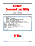
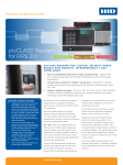
Wiegand Converter
Configuration Utility
User Manual
99009020 Rev B
Thank You!
Congratulations on the purchase of the Wiegand Converter. RF IDeas knows you will enjoy using the
converter board as much as we enjoyed creating and developing it! Configuration is easy so you will
be able to quickly take advantage of a more secure environment in your business, school, or
organization
Please call our Sales department if you have any questions or are interested in our OEM and
Independent Developer’s programs.
We look forward to your comments and suggestions for our product line! Please go to
www.RFIDeas.com and follow the Support a Learning Center link for more details about our
product line.
We are always discovering new applications for our product line(s). There are several software
developer’s licensing our technology so the solution you are looking for may already be developed.
Thank you,
The RF IDeas Staff
Need Assistance?
2
Ph: 847.870.1723
Fx: 847.483.1129
E: [email protected]
[email protected]
Contents
3
2
Thank You!
4
4
Chapter 1: The Basics
Wiegand Converter Overview
5
5
6
8
9
10
Chapter 2: Installation
Wiegand Converter Installation
Wiegand Converter Board Layout
RS-485/422 Connections
Jumper Locations
Connectors Locations
11
11
12
Chapter 3: Lock Connection
Push Button Magnetic Lock Connection
Magnetic Lock Connection
13
13
Chapter 4: Control Protocol
Serial OEM ASCII Control Protocol
15
Chapter 5: OEM-W2065 Connection Diagrams
17
Chapter 6: Glossary
18
23
24
Chapter 7: Support
Index
Other Products and Accessories
The Basics
1
Wiegand Converter Overview
Introduction to Reader
This family of Wiegand converters is suitable for OEMs that require up to 64 bits of Wiegand output
from a proximity card or other Wiegand device and convert to:
• OEM-W2065AKU AIR ID Playback USB
• OEM-W2USB – v3: USB (output as keystrokes or optional RF IDeas Software Developer’s Kit
via DLL)
• OEM-W2USB-CHUID USB (output as keystrokes or optional RF IDeas Software Developer’s
Kit via DLL)
• OEM-W2RS232 – V3m without relay
• OEM-2065AK2 AIR ID Playback RS – 232
• OEM-W2RS232 – v3: RS-232 data in ASCII format
• OEM-W2RS232 – CHUID: RS-232 data in ASCII format
• OEM-W2 - RS-485/422 - v3: RS - 485/422 data in ASCII format
The OEM Wiegand converter requires a regulated power source of 5 VDC or 8 – 16 VDC, 100mA for
internal operation.
The RS – 232 communications parameters are:
•
•
•
•
•
9600 baud
N no parity
8 data bits
1 stop bit
No hardware flow control
All data output is standard ASCII format. The converter contains flash memory and is configurable
with RF IDeas free configuration utility. The converter is capable of transferring data from proximity
devices with 26 to 64 bit data output lengths.
4
2
Installation
Wiegand Converter Installation
The following connection example shows a Wiegand output device (card reader) connected to a
typical DTE RS – 232 serial device using an external power supply.
Do not connect the Wiegand reader to LED1 or LED2 unless using your own application
Reader Wire Color
5 volts VRdr - Red
WO - Green
W1 - White
Gnd - Black
DTE Device
TX - 3 Pin
RX - 2 Pin
GND - Pin 5
5
Wiegand Converter Board Layout
Attach the USB cable before connecting the power.
Note: Verify jumper JP1 is NOT connected if using an external power supply.
Terminal Block Locations
Function
VH
V5
VRdr
SI
SO
6
Chapter 2
J4 TERMINAL BLOCK
Description
INPUT: Voltage (High), Power supply input from your power supply. The supply must be 8 –
16 VDC @100ma maximum. The on-board 5V regulator handles 1A combined consumption
so external consumers connected to the 5V bus are limited to 900mA
INPUT: This pin requires a regulated 5 VDC @100 ma
OUTPUT: 5vdc at up to 50ma - usually red wire from device
INPUT: Serial In when using in TTL mode and jumper JP5 connected
On Playback OEM version this is used for the Receive RS – 232
OUTPUT: Serial Output when using in TTL mode and jumper JP5 connected
On Playback OEM version this is used for the Transmit RS – 232
Installation
Function
W0
J4 TERMINAL BLOCK
Description
INPUT: Data 0 Wiegand – usually green wire from device
W1
Cable: 5 conductor (#22 AWG) stranded with continuous shield for typical Wiegand
installations
INPUT: Data 1 Wiegand - usually white wire from device
Gnd
Cable: 5 conductor (#22 AWG) stranded with continuous shield for typical Wiegand
installations
DC Ground – usually black wire from device
Function
Rly
J3 TERMINAL BLOCK
Description
OUTPUT: External input switched to ground connected to relay coil. Can only be driven
low. The other side of the coil is 5v. Grounding this pin energizes the coil.
Rly NC
Not supported on OEM-W2RS232-V3M
OUTPUT: Relay normally closed when not energized
Rly C
Not supported on OEM-W2RS232-V3M
OUTPUT: Relay Common
Rly NO
Not supported on OEM-W2RS232-V3M
OUTPUT: Relay normally open when not energized
LED1
Green
Not supported on OEM-W2RS232-V3M
OUTPUT: Open collector switched to ground when LED is green. This tracks the on-board
LED
LED2
Red
Not supported on OEM-W2RS232-V3M
OUTPUT: This is open collector switched to ground when LED is
red
Bpr
Not supported on OEM-W2RS232-V3M
OUTPUT: Beeper Open collector switched to ground by serial protocol only
Gnd
Not supported on OEM-W2RS232-V3M
DC Ground
Note: The relay, LED and beeper functions above can be controlled using the software developer’s kit
(SDK) on USB and Serial models. The serial model can be also controlled with ASCII commands without
the use of the SDK.
7
Chapter 2
Installation
Function
V5
R-232
T-232
T-485A/422
T-485B/422
Function
R – 485A/422
R – 485B/422
Gnd
J2 TERMINAL BLOCK
Description
INPUT or OUTPUT: This pin as input requires a regulated 5 VDC @100 ma when
input, 5 VDC @ 50ma output when VH is supplying power
INPUT: Receive RS – 232 data
OUTPUT: Transmit RS – 232 data
OUTPUT: Differential Output: Transmit RS –485/422 data; R19 terminates this
transmit line 120 ohms
OUTPUT: Transmit RS – 485/422 data
J4 TERMINAL BLOCK
Description
INPUT: Differential Input: Receive RS – 485/422 data R20 terminates this transmit
line 120 ohms
INPUT: Receive RS – 485/422 data
DC Ground
RS - 485/422 Connections
The RS – 485/422 physical connection must be a 4-wire, point-to-point connection to the host.
Multi drop (bridged) connections are NOT supported as the board does not tri-state the transmitter.
The TX lines may drive multiple receivers that are bridged together but no two TX pairs from different
modules should ever be connected together.
OEM Converter
TD (B) +
TD (A) RD (B) +
RD (A) GND
TD (B) +
TD (A) RD (B) +
RD (A) GND
OEM Converter
TD (B) +
TD (A) RD (R) +
RD (A) GND
Access Control
Access Control
TD (B) +
TD (A) RD (R) +
RD (A) GND
2-Wire Simplex Communications
8
Chapter 2 Installation
Jumper Locations
Jumpers
Function
NonInv/Inv
Description
The non-inverted Wiegand setting is normally high and pulsed low
JP1
The inverted form is normally low and pulsed high
This jumper has no effect on serial devices
When JP1 is installed, it connects the USB port + 5V to the W2U board’s + 5V
bus
VH should not be used. Any current draw from the 5V and VRdr terminals
should not exceed 50mA. Use this jumper only when no external power
supply is available
JP3 / JP4 / JP5
9
Chapter 2
Remove this jumper if board is externally powered. This could damage the
board if connected while powering via J11, VH, V5, or J10
Choose an RS – 232, RS – 485/422, TTL depending on the serial interface
required for the specific application. All transmit paths are live, however this
selects only one of the receive ports.
Installation
Connectors Locations
Connectors
Function
J1
Description
Internally used
J5
JP6 / JP7
Do not connect to this port
USB port
Only used when the Wiegand converter is programmed as an OEMW2065AK2
J10
J11
J16
10 Chapter 2 J10 is a polarized connector. Connect the serial cable with the 2m white plug
into J10.
• Pin 1 Ground (connect to pin 5 below)
• Pin 2 TX (output from board)
• Pin 3 RX (input to board)
• Pin 4 (Connect also to pin 6, pin 8 below)
• Pin 5 Ground
• Pin 6 (Connect also to pin 4, pin 8)
• Pin 7 This pin requires a regulated 5 VDC @100 ma
• Pin 8 (Connect also to pin 4, pin 6 above
INPUT: Voltage (High), Power supply input from your power supply. The supply
must be 8 – 16 VDC @100ma maximum
Mirrors J4
Pin 1 5v
Pin 2 same as VRdr
Pin 3 Reader reset (Indala)
Pin 4 W0
Pin 5 W1
Pin 6 Ground
Installation
Lock Connection
Push Button Magnetic Lock Connection
Note: The DC jack can also be used with the 12 volt power supply.
11
3
Magnetic Lock Connection
Note: The DC jack can also be used with the 12 volt power supply.
12
Chapter 3 Lock Connection
Control Protocol
4
Serial OEM ASCII Control Protocol
A secondary control protocol has been added to the version of the Serial OEM Prox (SOP). This
protocol enables the user to easily send control and associated configuration commands to the SOP
via a terminal emulator or other serial ASCII applications. All commands are case sensitive where the
alpha characters are capital. Successful reception and completion of the requested operation is
indicated by the return of an ASCII carriage return (0x0D) from the SOP. The communication
parameters are 9600-N-8-1 (9600 baud, 8 data bits, no parity bit, and 1 stop bit).
Relay
Form C relay with exposed open collector switch to Gnd coil drive. The ‘Rly’ terminal is the relay coil
driver collector and is not really “open” as it is tied to +5V through the relay coil and has a diode
across the coil for transient protection. This is always under user control. No delays to relay operation
can be set.
CONTROL OUTPUT COMMANDS
Relay
“OA0”
“OA1”
Output A (relay) OFF
Output A (relay) ON
Beeper
Beeper (BPR) switch to Gnd. This is always under user control.
CONTROL OUTPUT COMMANDS
Beeper
“OB0”
“OB1”
Output C (beeper) OFF
Output C (beeper) ON
Configuration Commands
LED1 (red) and LED2 (green) are configured to represent valid card reads by default. The last issued
configuration assignment is kept in non-volatile storage in the SOP so power cycling returns the
control to its last state. The non-volatile memory is EEPROM and has a finite (1,000,000 cycle and
40 year) lifetime. Configure the application so it does not approach this limit.
13
Chapter 4 Control Protocol
Send one of the following configuration commands to switch the control assignment:
CONFIGURATION COMMANDS
Control Assignment
“CLE”
LED1 and LED2 controlled externally
“CLI”
LED1 and LED2 controlled internally (default)
LED
LED1 OC switch to Gnd
•Under user control after configured for ‘external’ control.
•Follows on-board red LED when configured for ‘internal’ control.
•If configured for ‘internal’ control, nothing will happen and no response.
CONTROL OUTPUT COMMANDS
LED
“OC0”
“OC1”
Output A (red) OFF
Output A (red) ON
LED2
LED2 OD switch to Gnd
•Under user control after configured for ‘external’ control.
•Follows on-board green LED when configured for ‘internal’ control.
•If configured for ‘internal’ control, nothing will happen and no response.
Note: If the LED is configured using these commands, it will not be controlled by the Card Reader.
Communication Timeouts
Successive characters must be spaced at less than 2 seconds apart or the command will fail once an
opening command character is received.
There are two serial protocols in operation at a time. Wait two seconds before switching from one to
the other if the application requires both.
14
Chapter 4 Control Protocol
5
OEM-W2065 Connection Diagrams
Use the following diagrams to configure the reader to function as a playback device using model
numbers W2065AU or W2065AK2.
RW400 Reader Terminal Block Termination
HID 6121BKT0000
ORIG. RW400
P1-1
P1-4
P2-7
P2-7
P2-6
P2-3
P2-4
P1-3
P1-7
J4 BLOCK ON CONVERTER
CABLE COLORS
RED
VH
V5
VRdr
PINK
SI
GRAY
SO
GREEN
WO
WHITE
W1
BLACK
Gnd
P2-1
JP
7
6
RW400 TERMINAL BLOCK
POWER
10 TO 16 VDC, 300mA
(TO J4 BLOCK OR J11)
15
CONFIG JUMPERS
RW400 Reader Termination With a Cable
HID 6121BKN0000
J4 BLOCK ON CONVERTER
HID RW400 CABLE
RED
VH
V5
VRdr
PINK
SI
GRAY
SO
GREEN
WO
WHITE
W1
BLACK
Gnd
JP
7
6
POWER
10 TO 16 VDC, 300mA
(TO J4 BLOCK OR J11)
16
Chapter 5 OEM-W2065 Connection Diagrams
CONFIG JUMPERS
Glossary
Term
ASCII
AWG
Bpr
DLL
GND
LED
OC
OEM
RS-232
SDK
SOP
VH
17
6
Definition
American Standard Code for Information Interchange
American Wire Gauge
Beeper
Dynamic Link Library
Ground
Light Emitting Diode
Open Collector
Original Equipment Manufacturer
Recommended Standard 232 is a standard for serial binary data signals that are
commonly used in computer serial ports
Software Developer’s Kit
Serial OEM Prox
Voltage High – 8 to 16 volts
Support
7
Precautions
Do not mount the device directly on a metal surface. This could interfere with the RF signal and the
operation of the device.
The device may not recognize valid cards in the presence of high RF fields. If current readings are
erratic, take the following step:
· Move the equipment from any known transmitters nearby.
Contact Technical Support at 866.439.4884 for more information.
Before You Call Technical Support
Please make sure you’ve identified your reader model and credential type being used. Have this
information ready so that your call will be routed to the correct specialist.
For Assistance:
Ph: 847.870.1723
E: [email protected]
Talking To The Technician
Provide the reader model being used to the Technical Support Specialist.
Explain your problem to the specialist.
Be prepared to provide the following information:
- Error/problem explanation
- What you were doing when the problem occurred
- What steps you have taken to resolve the problem, including results from each steps
Listen and follow the steps provided by the specialist. Let the specialist know what happens when you
perform the steps.
18
END-USER LICENSE AGREEMENT
LICENSE AGREEMENT
End-User License Agreement for RF IDeas™ SOFTWARE and HARDWARE - RF IDeas’ pcProx®, Proximity Activated Readers, Software
Developer’s Kit, and Proximity Reader DLLs, and Protocol(s).
IMPORTANT-READ CAREFULLY: This End-User License Agreement (“EULA”) is a legal agreement between you (either an individual or a
single entity) and the manufacturer RF IDeas (“Manufacturer”) with which you acquired the RF IDeas software and hardware product(s)
identified above (“PRODUCT”). The PRODUCT includes the RF IDeas reader, computer software, the associated media, any printed
materials, and any “on line” or electronic documentation. By installing, copying or otherwise using the PRODUCT, you agree to be bound by
the terms of this EULA. The SOFTWARE PORTION OF THE PRODUCT includes the computer software, the associated media, any printed
materials, and any “on line” or electronic documentation. By installing, copying or otherwise using the PRODUCT, you agree to be bound by
the terms of this EULA. If you do not agree to the terms of this EULA, RF IDeas is unwilling to license the PRODUCT to you. In such event,
you may not use or copy the SOFTWARE PORTION OF THE PRODUCT, and you should promptly contact the vendor you obtained this
PRODUCT from for instructions on return of the unused product(s) for a refund.
The products described in this publication are intended for consumer applications. RF IDeas assumes no liability for the performance of
product. RF IDeas products are not suitable for use in life-support applications, biological hazard applications, nuclear control applications, or
radioactive areas. None of these products or components, software or hardware, are intended for applications that provide life support or any
critical function necessary for the support of protection of life, property or business interests. The user assumes responsibility for the use of
any of these products in any such application. RF IDeas shall not be liable for losses due to failure of any of these products, or components of
these products, beyond the RF IDeas commercial warranty, limited to the original purchase price.
SOFTWARE PRODUCT LICENSE The PRODUCT is protected by copyright laws and international copyright treaties, as well as other
intellectual property laws and treaties. The SOFTWARE PORTION OF THE PRODUCT is licensed, not sold.
1. GRANT OF LICENSE. This EULA grants you the following rights: *Software. You may install and use one copy of the SOFTWARE
PORTION OF THE PRODUCT on the COMPUTER. *Network Services. If the SOFTWARE PORTION OF THE PRODUCT includes
functionality that enables the COMPUTER to act as a network server, any number of computers or workstations may access or otherwise
utilize the basic network services of that server. The basic network services are more fully described in the printed materials accompanying
the SOFTWARE PORTION OF THE PRODUCT. *Storage/Network Use. You may also store or install a copy of the computer SOFTWARE
PORTION OF THE PRODUCT on the COMPUTER to allow your other computers to use the SOFTWARE PORTION OF THE PRODUCT
over an internal network, and distribute the SOFTWARE PORTION OF THE PRODUCT to your other computers over an internal network.
1.1 General License Grant RF IDeas grants to an individual, a personal, nonexclusive license to make and use copies of the SOFTWARE
PRODUCT for the sole purposes of designing, developing, and testing your software product(s) that are designed to operate in conjunction
with any RF IDeas designed proximity reader product. You may install copies of the SOFTWARE PRODUCT on an unlimited number of
computers provided that you are the only individual using the SOFTWARE PRODUCT. If you are an entity, RF IDeas grants the right to
designate one individual within your organization to have the sole right to use the SOFTWARE PRODUCT in the manner provided above.
1.2 Documentation. This EULA grants an individual, a personal, nonexclusive license to make and use an unlimited number of copies of any
documentation, provided that such copies shall be used only for personal purposes and are not to be republished or distributed (either in hard
copy or electronic form) beyond the user’s premises and with the following exception: you may use documentation identified in the
SOFTWARE PRODUCT as the file format specification for RF IDeas’ proximity readers solely in connection with your development of
software product(s) or an integrated work or product suite whose components include one or more general purpose software products.
1.3 Storage/Network Use. You may also store or install a copy of the SOFTWARE PRODUCT on a storage device, such as a network
server, used only to install or run the SOFTWARE PRODUCT on computers used by a licensed end user in accordance with Section 1.1. A
single license for the SOFTWARE PRODUCT may not be shared or used concurrently by other end users.
1.4 Sample Code. RF IDeas grants you the right to use and modify the source code version of those portions of the SOFTWARE
PRODUCT identified as “Samples in the SOFTWARE PRODUCT (“Sample Code”) for the sole purposes to design, develop, and test your
software product(s), and to reproduce and distribute the Sample Code, along with any modifications thereof, only in object code form.
2. DESCRIPTION OF OTHER RIGHTS AND LIMITATIONS.
*Limitations on Reverse Engineering, Decompilation and Disassembly. You may not reverse engineer, decompile, or disassemble the
PRODUCT, except and only to the extent that such activity is expressly permitted by applicable law notwithstanding this limitation
*You may not reproduce or otherwise emulate, in whole or in part, any form the protocol(s) defined within this PRODUCT for use
without a RF IDeas PRODUCT Redistributable Code. If you are authorized and choose to redistribute Sample Code (“Redistributables”) as
described in Section 1.4, you agree to: (a) distribute the Redistributables in object code only in conjunction with and as a part of a software
application product developed by you using the PRODUCT accompanying this EULA that adds significant and primary functionality to the
SOFTWARE PRODUCT (“Licensed Product”); (b) not use RF IDeas’ name, logo, or trademarks to market the Licensed Product; (c) include a
valid copyright notice on the Licensed Product; (d) indemnify, hold harmless, and defend RF IDeas from and against any claims or lawsuits,
including attorney’s fees, that arise or result from the use or distribution of the Licensed Product; (e) otherwise comply with the terms of this
EULA; and (g) agree that RF IDeas reserves all rights not expressly granted. You also agree not to permit further distribution of the
Redistributables by your end users except: (1) you may permit further redistribution of the Redistributables by your distributors to your
end-user customers if your distributors only distribute the Redistributables in conjunction with, and as part of, the Licensed Product and you
and your distributors comply with all other terms of this EULA; and (2) in the manner described in Section 1.4.
*Separation of Components. The PRODUCT is licensed as a single product. Its component parts may not be separated for use on more than
one computer.
*Single COMPUTER. The PRODUCT is licensed with the COMPUTER as a single integrated product. The PRODUCT may only be used with
the COMPUTER.
*Rental. You may not rent or lease the PRODUCT without permission from RF IDeas
*Software Transfer. You may permanently transfer all of your rights under this EULA only as part of a sale or transfer of the COMPUTER,
provided you retain no copies, you transfer all of the PRODUCT (including all component parts, the media and printed materials, any
upgrades, this EULA and, if applicable, the Certificate(s) of Authenticity), AND the recipient agrees to the terms of this EULA. If the
PRODUCT is an upgrade, any transfer must include all prior versions of the PRODUCT.
*Termination. Without prejudice to any other rights, RF IDeas may terminate this EULA if you fail to comply with the terms and conditions
of this EULA. In such event, you must destroy all copies of the SOFTWARE PORTION OF THE PRODUCT and all of its component parts.
3. UPGRADES. If the SOFTWARE PORTION OF THE PRODUCT is an upgrade from another product, whether from RF IDeas or another
supplier, you may use or transfer the PRODUCT only in conjunction with that upgraded product, unless you destroy the upgraded product. If
the SOFTWARE PORTION OF THE PRODUCT is an upgrade of a RF IDeas product, you now may use that upgraded product only in
nn
19
accordance with this EULA. If the SOFTWARE PORTION OF THE PRODUCT is an upgrade of a component of a package of software
programs which you licensed as a single product, the SOFTWARE PORTION OF THE PRODUCT may be used and transferred only as part
of that single product package and may not be separated for use on more than one computer.
4. OEM COPYRIGHT. All title and copyrights in and to the PRODUCT (including but not limited to images, photographs, animations, video,
audio, music, text and “applets,” incorporated into the PRODUCT), the accompanying printed materials, and any copies of the SOFTWARE
PORTION OF THE PRODUCT, are owned by RF IDeas or its suppliers. The PRODUCT and SOFTWARE PORTION OF THE PRODUCT is
protected by copyright laws and international treaty provisions. You may not copy the printed materials accompanying the PRODUCT.
5. DUAL-MEDIA SOFTWARE. You may receive the SOFTWARE PORTION OF THE PRODUCT in more than one medium. Regardless of
the type or size of medium you receive, you may use only one medium that is appropriate for your single computer. You may not use or install
the other medium on another computer. You may not loan, rent, lease, or otherwise transfer the other medium to another user, except as part
of the permanent transfer (as provided above) of the SOFTWARE PORTION OF THE PRODUCT.
6. OEM PRODUCT SUPPORT. Product support for the product is not provided by RF IDeas or its subsidiaries. For product support, please
refer to the OEM supplies support number provided in the documentation. Should you have any questions concerning the EULA, or if you
desire to contact OEM for any other reason, please refer to the address provided in the documentation provided.
FOR THE LIMITED WARRANTIES AND SPECIAL PROVISIONS PERTAINING TO YOUR PARTICULAR JURISDICTION, PLEASE REFER
TO YOUR WARRANTY BOOKLET INCLUDED WITH THIS PACKAGE OR PROVIDED WITH THE SOFTWARE PRODUCT PRINTED
MATERIALS.
Limited Warranty: RF IDeas warrants to the original buyer of this product, that the hardware and related disk(s) are free of defects in
material and workmanship for a period of one year from date of purchase from RF IDeas or from an authorized RF IDeas dealer. Should the
RF IDeas products fail to be in good working order at any time during the one-year period, RF IDeas will, at its option, repair or replace the
product at no additional charge, provided that the product has not been abused, misused, repaired or modified. This warranty shall be limited
to repair or replacement and in no event shall RF IDeas be liable for any loss of profit or any commercial or other damages,
including but not limited to special, incidental, consequential or other similar claims.
No dealer, distributor, company, or person has been authorized to change or add to the terms of this agreement, and RF IDeas will not be
bound by any representation to the contrary. RF IDeas SPECIFICALLY DISCLAIMS ALL OTHER WARRANTIES, EXPRESSED OR
IMPLIED, INCLUDING BUT NOT LIMITED TO IMPLIED WARRANTIES OF MERCHANTABILITY AND FITNESS OF PURPOSE. Since some
states do not allow such exclusion of limitation of incidental or consequential damages for consumer products, check the statute of
the state in which your business resides. This warranty gives you the specific legal rights in addition to any rights that you have under the
laws of the state in which your business resides or operates.
Returns: RF IDeas products which require Limited Warranty service during the warranty period shall be delivered to the nearest authorized
dealer or sent directly to RF IDeas at the address below with proof of purchase and a Return Materials Authorization (RMA) Number provided
by RF IDeas Technical Support Dept. Replacement parts or complete boards become the property of RF IDeas If the returned board or unit
is sent by mail, the purchaser agrees to pre-pay the shipping charges and insure the board or unit or assume the risk of loss or damage which
may occur in transit. The purchaser is expected to employ a container equivalent to the original packaging.
Copyright: Copyright by RF IDeas. All rights reserved. Reproduction or distribution of this document in whole or in part or in any form is
prohibited without express written permission from RF IDeas.
Trademarks: All RF IDeas products are trademarks of RF IDeas. All other product names or names are trademarks or registered
trademarks of their respective holders.
Applicable Patents: RF IDeas pcProx Plus card readers supporting HID formats retain US Patent No. 5,952,935 and U.S. Patent No.
7,439,862.
Disclaimer: This Reference Guide is printed in the U.S.A. Any resemblance mentioned in the Reference Guide to persons living or dead, or
to actual corporations or products is purely coincidental. RF IDeas believes that the information contained in this manual is correct.
However, RF IDeas does not assume any responsibility for the accuracy of the content of this User Manual, nor for any patent infringements
or other rights of third parties. RF IDeas reserves the right to make any modifications in either product or the manual without giving prior
written notification.
FCC Compliance Statement
FCC ID: M9MPCPROXHUSB100 (HID USB model) FCC ID: M9MPCPROXM101 (Indala model) FCC ID: M9MRDR6X8X (Kantech, Indala, Casi-Rusco) FCC ID: M9MPCPROXC101 (Casi-Rusco model) FCC ID: M9MRFID1856I100 (MIFARE/iCLASS models) FCC ID: M9MRDR7081 (iCLASS Module based) FCC ID: M9MRDR7581 (iCLASS MIFARE and Other 13.56MHz) FCC ID: M9MRDR7081AKE (iCLASS MIFARE and Other 13.56MHz) FCC ID: M9MRDR758X (iCLASS MIFARE and Other 13.56 MHz)
FCC ID: M9M758XCCL (MIFARE and Contact model) FCC ID: M9MBUPCPROXH100 (HID RS-232 model)
FCC ID: M9MBUPCPROXA100 (AWID)
FCC ID: M9MPCPROXP100 (Pyramid)
FCC ID: M9MRDR7P71 (FIPS 201 13.56MHz)
FCC ID: M9MRDR7L81 (Legic 13.56MHz)
FCC ID: M9MRDR7580 (iCLASS MIFARE and Other 13.56MHz)
FCC ID: M9MRDR7081AKF (iCLASS MIFARE and Other 13.56MHz)
FCC ID: M9MRDR75DX (iCLASS MIFARE and Other 13.56MHz)
FCC ID: M9M8058XCCL (Multi-protocol and Contact model)
FCC ID: M9M7580CCL (MIFARE and Contact model)
“Pursuant to FCC 15.21 of the FCC rules, changes not expressly approved by RF IDeas might cause harmful interference and void the FCC
authorization to operate this product.
Changes to this product not expressly approved by RF IDeas will void the user’s authority to operate the equipment.
Note: This device complies with Part 15 of the FCC Rules and Industry Canada license-exempt RSS standard(s). Operation is subject to
the following two conditions: (1) This device may not cause harmful interference, and (2) this device must accept any interference received,
including interference that may cause undesired operation. This product complies with FCC OET Bulletin 65 radiation exposure limits set forth
for an uncontrolled environment.
The reader may not recognize value cards in the presence of high RF fields. If the current reading is erratic, the user shall take the following
step: Move the equipment from any known transmitters nearby. For more information contact Tech Support at 866.439.4884.
20
Index
Index
A
O
ASCII
AWG
4, 13, 17
17
OA0
OA1
OB0
OB1
OC
OC0
OC1
B
Bpr
7, 13, 17
C
CLE
14
CLI
14
Communication Timeouts
R
Rly
7, 13
Rly C
7
Rly NC
7, 11, 12
Rly NO
7
R-232
8
R-422
8
R-485
8
RS-232
4, 17
14
D
DLL
DTE
17
5
E
EEPROM
13
13
13
13
17
14
14
13
S
G
Gnd
Serial OEM Prox (SOP)
SDK
17
SI
6, 15, 16
SO
6, 15, 16
7, 8, 11, 12, 13, 14, 15, 16, 17
J
J1
J5
J10
J11
J16
JP1
JP3
JP4
JP5
JP6
JP7
10
10
10
10
10
9
9
9
9
10
10
T
T-232
8
T-422
8
T-485
8
Terminal Block Locations
TX Lines
8
TX Pairs
8
V
L
LED
V5
VH
VRdr
6, 8, 15, 16
6, 11, 12, 15, 16, 17
6, 15, 16
W0
W1
7, 15, 16
7, 15, 16
5, 13, 14, 17
W
21
13, 17
6
Other Products & Accessories
Software Developer’s Kit
Allows independent
developer’s to use their
application to read proximity
access badge Read ID data
of more than 1 billion cards
in the field
PVC Label Proximity Card
Credit card size with paper
release liner, 500 cards per
box
Proximity Cards, Labels, Key
Fobs
Complete selection of various
manufacturers proximity cards,
labels and key fobs. Marked
with data code and ID number,
available in several Wiegand
formats
pcProx Read/Write
Contactless
Reads and writes directly to
the smart cards
pcProx Writer and Playback
Desktop read-only for
iCLASS and NXP and smart
cards
pcProx Playback Starter Kit
Plays back card sector data
in ASCII or keystrokes
pcProx Sonar
Presence detector configured
as a keyboard
22
PS/2 to USB Power Tap
Powers a USB RF IDeas device
from a PS/2 port
Mounting Brackets
Further adjust the standard
mounting of the device angle
RF IDeas Inc.
© 2013 RF IDeas. All rights reserved.
Specifications subject to change without notice.
Windows, Macintosh, Solaris, Sun Ray and Linux are trademarks of their respective companies.
All other trademarks, service marks and product or service names are property of their respective owners.
Mention of third-party products is for informational purposes only and constitutes neither an endorsement nor a
recommendation. RF IDeas assumes no responsibility with regard to the performance or use of these products.
All understandings, agreements, or warranties, if any, take place directly between the vendors and the prospective users.
Please feel free to call, e-mail or visit our web site for a full list of applications, products, configuration options, supported
cards and form factor specifications. Our web site includes application videos, support materials, case studies and
detailed information about our product line.
Every effort has been made to ensure that the information in this manual is accurate. RF IDeas is not responsible for printing or
clerical errors.
70