1
20PU05-00 E4 – 2014-10-22
User Manual
PU5/PU6/PU8 – 3U 12HP
wide-range PSUs for 19"
systems
110, 24 or 36 VDC nom.
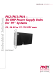
PU5 - 3U 12 HP Power Supply Unit PSU, 110 VDC, 100 W
PU5 - 3U 12 HP Power Supply Unit PSU, 110 VDC, 100 W
The PU5 is a plug-in power supply unit for 19" systems (e.g. VMEbus,
CompactPCI®) and is especially designed for computer systems in public transport
vehicles, being fully compliant with EN 50155.
The PU5 has a nominal input voltage of 110 VDC with a wide input range of
77..137.5 V and a max. input voltage range of 66..154 V (according to EN50155).
The otherwise identical PSU models PU6 and PU8 are available for the nominal
input voltages of 24 VDC and 36 VDC respectively.
It is controlled by a microprocessor which supervises the voltage and the
temperature as well as one external input (for its key input function) and one output.
Thanks to the onboard intelligence the PSU can also act as an SMBus slave and
communicate with the CPU board via the backplane. This allows the PSU to power
on the system at a programmed date and enables the CPU to make status polls with
regard to, e.g., error messages, time-out or on/off.
The PSU provides a DC/DC converter to generate the isolated 12 V from the input
voltage. Two regulators generate 5 V and 3.3 V from the 12 V isolated side. The
maximum power at full load is 100 W, minimum power is 5 W. The microprocessor
is supplied with power independently and can turn off the main DC/DC converter to
switch the unit into standby mode (power consumption less than 6 W).
The subassembly is conformally coated, and components are secured against
vibration. The PSU operates in -40 to +85°C environmental temperature. The
thermal stress is extremely low due to integrated heat sinks and diversion of
dissipated heat over the mounting surface.
MEN Mikro Elektronik GmbH
20PU05-00 E4 – 2014-10-22
2
Diagram
Diagram
Vin
FET 12 V
Switch
Filter
DC/DC 100 W
Input Vin
Output 12 V
Vin
Stepdown Regulator
12 V to 5 V
5 V
12 V to 3.3 V
3.3 V
On/Off (Standby Mode)
Front Connector
Rear Connector
Reset
BININ (Key)
Isolation / Relay
Microcontroller
BINOUT
DC/DC
0.75 W
SMB
Voltage Monitoring
Temperature Monitoring
MEN Mikro Elektronik GmbH
20PU05-00 E4 – 2014-10-22
3
Technical Data
Technical Data
Microcontroller
•
•
•
•
•
Output voltage and temperature supervision (readable via SMBus)
Overtemperature and overvoltage shutdown
Communication with CPU
Watchdog functionality
Independent power supply for operation during standby mode (power
consumption less than 1 W)
SMBus
•
•
•
•
Signals on back connector
Voltage level 3.3V
Controlled by CPU
Communication between the power supply unit and the CPU
Binary I/O
• 1 binary input
- Voltage level according to external power supply input voltage (max. 154
VDC)
- Electrically isolated
- External switch (key) with binary input
- Switch-on by key input or wake on time
- Switch-off by key input or software
- Status of binary inputs readable via SMBus
• 1 binary output
- Voltage level according to external power supply input voltage
- Isolated by relays
- User-specific functionality (controllable via SMBus)
- Maximum switching power: 60W (example 110V/0.5A)
Miscellaneous
• DC/DC Converter
- Fuse-protected
• Two status LEDs on front panel
- Green LED indicates correct input voltage
- Yellow LED indicates correct output voltage
• Alternative power supply at the backplane for use as redundant PSU
• Short circuit protection
• Reverse polarity protection by internal protector
Input Characteristics
• Nominal voltage input: 110 VDC
MEN Mikro Elektronik GmbH
20PU05-00 E4 – 2014-10-22
4
Technical Data
• Wide input range: 0.7 x nominal voltage < nominal voltage < 1.25 x nominal
voltage (according to EN50155)
- 77..137.5 VDC
• Max. input voltage range: 0.6 x nominal voltage < nominal voltage < 1.4 x
nominal voltage with full functionality for 0.1 s, no damage for 1 s (according to
EN50155)
- 66..154 VDC
• No load input power: < 5.8 W in standby mode
Output Characteristics
•
•
•
•
•
•
•
Output power (max.): 100W
Output power (min.): 5W
12V tolerance/overvoltage protection: ±5%
5V tolerance/overvoltage protection: +5%/-3%
3.3V tolerance/overvoltage protection: ±3%
Overtemperature shutdown: 50×..90×(adjustable by SMBus command)
Holdup time according to EN50155 Class S2
Connection
• Input and output via DIN 41612 plug connector, type H15
Electrical Specifications
• Isolation (according to EN50155)
- Input/output: 1500VDC/1000V eff
- Input/shield: 1500VDC/1000V eff
- Output/shield: 1500VDC/1000V eff
- Ground/shield: 1500VDC/1000V eff
Mechanical Specifications
• Dimensions: 3U, 12HP, 128.4mm height
• Integrated heat sink
• Weight: 1.1 kg
Environmental Specifications
•
•
•
•
•
•
•
Temperature range (operation): -40..+85°C (no derating)
Temperature range (storage): -40..+85°C
Airflow: min. 10m³/h
Shock: according to EN60068-2-27
Continuous shock: according to EN60068-2-29
Vibration: according to EN60068-2-6
Protection
- Class of protection: Class II, EN 60950
- Degree of protection: IP20 (insert in rack), EN60529
MTBF
• 190,000+ h @ 40°C according to IEC/TR 62380 (RDF 2000)
MEN Mikro Elektronik GmbH
20PU05-00 E4 – 2014-10-22
5
Technical Data
EMC
• Tested according to EN55022 (radio disturbance), EN61000-4-2 (ESD),
EN61000-4-4 (burst) and EN61000-4-5 (surge)
Software Support
• Driver software for SMB communication for Windows®, Linux, VxWorks®
For more information on supported operating system versions and
drivers, please see the online data sheet.
MEN Mikro Elektronik GmbH
20PU05-00 E4 – 2014-10-22
6
Configuration Options
Configuration Options
Mechanical Specifications
• 8HP model with smaller heat sink and derating tbd.
Please note that some of these options may only be available for large volumes.
Please ask our sales staff for more information.
For available standard configurations see the online data sheet.
MEN Mikro Elektronik GmbH
20PU05-00 E4 – 2014-10-22
7
Product Safety
Product Safety
Electrostatic Discharge (ESD)
!
MEN Mikro Elektronik GmbH
20PU05-00 E4 – 2014-10-22
Computer boards and components contain electrostatic sensitive
devices. Electrostatic discharge (ESD) can damage components. To
protect the board and other components against damage from static
electricity, you should follow some precautions whenever you work on
your computer.
• Power down and unplug your computer system when working on the
inside.
• Hold components by the edges and try not to touch the IC chips,
leads, or circuitry.
• Use a grounded wrist strap before handling computer components.
• Place components on a grounded antistatic pad or on the bag that
came with the component whenever the components are separated
from the system.
• Only store the board in its original ESD-protected packaging. Retain
the original packaging in case you need to return the board to MEN
for repair.
8
About this Document
About this Document
This user manual is intended only for system developers and integrators, it is not
intended for end users.
It describes the hardware functions of the board, connection of peripheral devices
and integration into a system. It also provides additional information for special
applications and configurations of the board.
The manual does not include detailed information on individual components (data
sheets etc.). A list of literature is given in the appendix.
History
Issue
Comments
Date
E1
First edition
2009-06-30
E2
Updated standard width to 12HP, new cover photo
2010-06-24
PU8 added to PSU models covered by this manual
Added more detailed information regarding input
voltage range
Corrected "no load input power" in technical data
Cosmetics
E3
Corrected pin assignment: removed SD_INT signals and alternate power inputs (not relevant for
standard models), clarified pin assignment regarding binary outputs, updated block diagram accordingly
2010-12-20
Added connection example figure
Added figure to binary output sub-chapter
Added information regarding use in a redundant
system with multiple PUx models connected in parallel
Cosmetics
E4
MEN Mikro Elektronik GmbH
20PU05-00 E4 – 2014-10-22
Corrected current rating of fuses
2014-10-22
9
About this Document
Conventions
Indicates important information or warnings concerning the use of
voltages that could lead to a hazardous situation which could result in
personal injury, or damage or destruction of the component.
!
Indicates important information or warnings concerning proper
functionality of the product described in this document.
The globe icon indicates a hyperlink that links directly to the Internet,
where the latest updated information is available.
When no globe icon is present, the hyperlink links to specific elements
and information within this document.
italics
Folder, file and function names are printed in italics.
bold
Bold type is used for emphasis.
mono
A monospaced font type is used for hexadecimal numbers, listings, C
function descriptions or wherever appropriate. Hexadecimal numbers
are preceded by "0x".
comment
Comments embedded into coding examples are shown in green text.
IRQ#
/IRQ
Signal names followed by a hashtag "#" or preceded by a forward
slash "/" indicate that this signal is either active low or that it becomes
active at a falling edge.
in/out
Signal directions in signal mnemonics tables generally refer to the
corresponding board or component, "in" meaning "to the board or
component", "out" meaning "from it the board or component".
Blue vertical lines in the outer margin indicate sections where changes
have been made to this version of the document.
MEN Mikro Elektronik GmbH
20PU05-00 E4 – 2014-10-22
10
About this Document
Legal Information
Changes
MEN Mikro Elektronik GmbH ("MEN") reserves the right to make changes without further notice to any products
herein.
Warranty, Guarantee, Liability
MEN makes no warranty, representation or guarantee of any kind regarding the suitability of its products for any
particular purpose, nor does MEN assume any liability arising out of the application or use of any product or
circuit, and specifically disclaims any and all liability, including, without limitation, consequential or incidental
damages. TO THE EXTENT APPLICABLE, SPECIFICALLY EXCLUDED ARE ANY IMPLIED
WARRANTIES ARISING BY OPERATION OF LAW, CUSTOM OR USAGE, INCLUDING WITHOUT
LIMITATION, THE IMPLIED WARRANTIES OF MERCHANTABILITY AND FITNESS FOR A
PARTICULAR PURPOSE OR USE. In no event shall MEN be liable for more than the contract price for the
products in question. If buyer does not notify MEN in writing within the foregoing warranty period, MEN shall
have no liability or obligation to buyer hereunder.
The publication is provided on the terms and understanding that:
1. MEN is not responsible for the results of any actions taken on the basis of information in the publication, nor
for any error in or omission from the publication; and
2. MEN is not engaged in rendering technical or other advice or services.
MEN expressly disclaims all and any liability and responsibility to any person, whether a reader of the publication
or not, in respect of anything, and of the consequences of anything, done or omitted to be done by any such person
in reliance, whether wholly or partially, on the whole or any part of the contents of the publication.
Conditions for Use, Field of Application
The correct function of MEN products in mission-critical and life-critical applications is limited to the
environmental specification given for each product in the technical user manual. The correct function of MEN
products under extended environmental conditions is limited to the individual requirement specification and
subsequent validation documents for each product for the applicable use case and has to be agreed upon in writing
by MEN and the customer. Should the customer purchase or use MEN products for any unintended or
unauthorized application, the customer shall indemnify and hold MEN and its officers, employees, subsidiaries,
affiliates, and distributors harmless against all claims, costs, damages, and expenses, and reasonable attorney fees
arising out of, directly or indirectly, any claim or personal injury or death associated with such unintended or
unauthorized use, even if such claim alleges that MEN was negligent regarding the design or manufacture of the
part. In no case is MEN liable for the correct function of the technical installation where MEN products are a part
of.
Trademarks
All products or services mentioned in this publication are identified by the trademarks, service marks, or product
names as designated by the companies which market those products. The trademarks and registered trademarks
are held by the companies producing them. Inquiries concerning such trademarks should be made directly to those
companies.
Conformity
MEN products are no ready-made products for end users. They are tested according to the standards given in the
Technical Data and thus enable you to achieve certification of the product according to the standards applicable in
your field of application.
MEN Mikro Elektronik GmbH
20PU05-00 E4 – 2014-10-22
11
About this Document
RoHS
Since July 1, 2006 all MEN standard products comply with RoHS legislation.
Since January 2005 the SMD and manual soldering processes at MEN have already been completely lead-free.
Between June 2004 and June 30, 2006 MEN’s selected component suppliers have changed delivery to RoHScompliant parts. During this period any change and status was traceable through the MEN ERP system and the
boards gradually became RoHS-compliant.
WEEE Application
The WEEE directive does not apply to fixed industrial plants and tools. The compliance is the responsibility of the
company which puts the product on the market, as defined in the directive; components and sub-assemblies are
not subject to product compliance.
In other words: Since MEN does not deliver ready-made products to end users, the WEEE directive is not
applicable for MEN. Users are nevertheless recommended to properly recycle all electronic boards which have
passed their life cycle.
Nevertheless, MEN is registered as a manufacturer in Germany. The registration number can be provided on
request.
Copyright © 2014 MEN Mikro Elektronik GmbH. All rights reserved.
Germany
MEN Mikro Elektronik GmbH
Neuwieder Straße 3-7
90411 Nuremberg
Phone +49-911-99 33 5-0
Fax +49-911-99 33 5-901
E-mail [email protected]
www.men.de
MEN Mikro Elektronik GmbH
20PU05-00 E4 – 2014-10-22
France
MEN Mikro Elektronik SAS
18, rue René Cassin
ZA de la Châtelaine
74240 Gaillard
Phone +33 (0) 450-955-312
Fax +33 (0) 450-955-211
E-mail [email protected]
www.men-france.fr
USA
MEN Micro Inc.
860 Penllyn Blue Bell Pike
Blue Bell, PA 19422
Phone (215) 542-9575
Fax (215) 542-9577
E-mail [email protected]
www.menmicro.com
12
Contents
Contents
1 Getting Started . . . . . . . . . . . . . . . . . . . . . . . . . . . . . . . . . . . . . . . . . . . . . . . .
1.1 Map of the Board. . . . . . . . . . . . . . . . . . . . . . . . . . . . . . . . . . . . . . . . .
1.2 Integrating the Board into a System . . . . . . . . . . . . . . . . . . . . . . . . . .
1.3 Installing Driver Software . . . . . . . . . . . . . . . . . . . . . . . . . . . . . . . . . .
16
16
16
16
2 Connecting the PSU . . . . . . . . . . . . . . . . . . . . . . . . . . . . . . . . . . . . . . . . . . . . 17
2.1 Using the PSU in a Redundant Configuration. . . . . . . . . . . . . . . . . . . 18
3 Functional Description . . . . . . . . . . . . . . . . . . . . . . . . . . . . . . . . . . . . . . . . . .
3.1 Microcontroller . . . . . . . . . . . . . . . . . . . . . . . . . . . . . . . . . . . . . . . . . .
3.2 Power Up . . . . . . . . . . . . . . . . . . . . . . . . . . . . . . . . . . . . . . . . . . . . . . .
3.3 Power Down . . . . . . . . . . . . . . . . . . . . . . . . . . . . . . . . . . . . . . . . . . . .
3.4 Binary I/O . . . . . . . . . . . . . . . . . . . . . . . . . . . . . . . . . . . . . . . . . . . . . .
3.4.1
Binary Input . . . . . . . . . . . . . . . . . . . . . . . . . . . . . . . . . . . . .
3.4.2
Binary Output . . . . . . . . . . . . . . . . . . . . . . . . . . . . . . . . . . . .
3.5 Status LEDs . . . . . . . . . . . . . . . . . . . . . . . . . . . . . . . . . . . . . . . . . . . . .
3.6 SMBus . . . . . . . . . . . . . . . . . . . . . . . . . . . . . . . . . . . . . . . . . . . . . . . . .
3.6.1
General . . . . . . . . . . . . . . . . . . . . . . . . . . . . . . . . . . . . . . . . .
3.6.2
SMBus Interface . . . . . . . . . . . . . . . . . . . . . . . . . . . . . . . . . .
3.6.3
Wake On Time. . . . . . . . . . . . . . . . . . . . . . . . . . . . . . . . . . . .
3.6.4
Watchdog. . . . . . . . . . . . . . . . . . . . . . . . . . . . . . . . . . . . . . . .
3.6.5
Status of Binary Input and Output . . . . . . . . . . . . . . . . . . . .
3.6.6
Key Input. . . . . . . . . . . . . . . . . . . . . . . . . . . . . . . . . . . . . . . .
3.6.7
Shutdown. . . . . . . . . . . . . . . . . . . . . . . . . . . . . . . . . . . . . . . .
3.6.8
Voltage and Current Supervision . . . . . . . . . . . . . . . . . . . . .
3.6.9
Temperature Supervision . . . . . . . . . . . . . . . . . . . . . . . . . . .
3.6.10 PSU ID and Firmware Revision Number . . . . . . . . . . . . . . .
3.7 DC/DC Converter . . . . . . . . . . . . . . . . . . . . . . . . . . . . . . . . . . . . . . . .
3.7.1
Fuse Protection . . . . . . . . . . . . . . . . . . . . . . . . . . . . . . . . . . .
19
19
20
20
20
20
21
22
22
22
22
23
23
25
26
27
31
32
33
34
34
4 Appendix . . . . . . . . . . . . . . . . . . . . . . . . . . . . . . . . . . . . . . . . . . . . . . . . . . . . . 35
4.1 Literature and Web Resources . . . . . . . . . . . . . . . . . . . . . . . . . . . . . . . 35
4.2 Finding out the Board’s Article Number, Revision and Serial Number35
MEN Mikro Elektronik GmbH
20PU05-00 E4 – 2014-10-22
13
Figures
Figure 1.
Figure 2.
Figure 3.
Figure 4.
Figure 5.
Figure 6.
Figure 7.
Figure 8.
MEN Mikro Elektronik GmbH
20PU05-00 E4 – 2014-10-22
Map of the board – front panel and top view . . . . . . . . . . . . . . . . . . . .
Connection example . . . . . . . . . . . . . . . . . . . . . . . . . . . . . . . . . . . . . . .
Microcontroller block diagram. . . . . . . . . . . . . . . . . . . . . . . . . . . . . . .
Power up by key input . . . . . . . . . . . . . . . . . . . . . . . . . . . . . . . . . . . . .
Binary output relay . . . . . . . . . . . . . . . . . . . . . . . . . . . . . . . . . . . . . . . .
Shutdown sequence . . . . . . . . . . . . . . . . . . . . . . . . . . . . . . . . . . . . . . .
Position of fuse for DC/DC converter protection. . . . . . . . . . . . . . . . .
Labels giving the board’s article number, revision and serial number.
16
18
19
20
21
30
34
35
14
Tables
Table 1.
Table 2.
Table 3.
Table 4.
Table 5.
Table 6.
Table 7.
Table 8.
Table 9.
Table 10.
Table 11.
Table 12.
Table 13.
Table 14.
Table 15.
Table 16.
Table 17.
Table 18.
Table 19.
Table 20.
Table 21.
Table 22.
Table 23.
MEN Mikro Elektronik GmbH
20PU05-00 E4 – 2014-10-22
Pin assignment of H15 PSU connector (front) . . . . . . . . . . . . . . . . . . .
Pin assignment of H15 PSU connector (rear). . . . . . . . . . . . . . . . . . . .
Signal mnemonics of PSU interfaces . . . . . . . . . . . . . . . . . . . . . . . . . .
Status LEDs on the front panel. . . . . . . . . . . . . . . . . . . . . . . . . . . . . . .
SMBus commands for wake on time function . . . . . . . . . . . . . . . . . . .
SMBus commands AD78C_WOT_L/ AD78C_WOT_H . . . . . . . . . .
SMBus commands for watchdog function . . . . . . . . . . . . . . . . . . . . . .
SMBus command AD78C_WDOG_TOUT. . . . . . . . . . . . . . . . . . . . .
SMBus commands for binary input/output status . . . . . . . . . . . . . . . .
SMBus commands for on acknowledge function. . . . . . . . . . . . . . . . .
SMBus on acknowledge timer modes . . . . . . . . . . . . . . . . . . . . . . . . .
SMBus command for shutdown by software function . . . . . . . . . . . . .
SMBus commands for shutdown delay . . . . . . . . . . . . . . . . . . . . . . . .
SMBus command AD78C_STATUS. . . . . . . . . . . . . . . . . . . . . . . . . .
SMBus command AD78C_DOWN_DELAY . . . . . . . . . . . . . . . . . . .
SMBus command for off delay function . . . . . . . . . . . . . . . . . . . . . . .
SMBus command AD78C_OFF_DELAY . . . . . . . . . . . . . . . . . . . . . .
SMBus command for off acknowledge function . . . . . . . . . . . . . . . . .
MDIS Channels for the PU5/PU6/PU8 . . . . . . . . . . . . . . . . . . . . . . . .
SMBus voltage supervision commands . . . . . . . . . . . . . . . . . . . . . . . .
SMBus commands for temperature supervision. . . . . . . . . . . . . . . . . .
SMBus command AD78C_TEMP_HIGH . . . . . . . . . . . . . . . . . . . . . .
SMBus commands for PSU ID and firmware revision number . . . . . .
17
17
17
22
23
23
24
24
25
26
27
27
28
28
28
29
29
29
31
31
32
32
33
15
Getting Started
1
Getting Started
This chapter gives an overview of the board and some hints for first installation in a
system.
1.1
Map of the Board
Figure 1. Map of the board – front panel and top view
DC/DC Converter
H15 Connector Rear
H15 Connector Front
Status LEDs
H15 Connector Front
Mounting screws
Fuse
Handle
Mounting screws
1.2
Integrating the Board into a System
!
1.3
This chapter gives important information on first installation of the
PU5/PU6/PU8.
• Power down the system before installing or removing the PU5/PU6/
PU8.
• Only operate the PU5/PU6/PU8 in a suitable housing, i.e. in such a
way that no parts of the PU5/PU6/PU8 except the front panel can
be touched.
• Make sure that enough airflow is provided.
• Do not remove any covers or other mechanical parts.
• The guiderails should be made of synthetic material and not touch
any components.
Installing Driver Software
For a detailed description on how to install driver software please refer to the
respective documentation.
You can find any driver software available for download on MEN’s
website.
MEN Mikro Elektronik GmbH
20PU05-00 E4 – 2014-10-22
16
Connecting the PSU
2
Connecting the PSU
The PU5/PU6/PU8 can be connected via two H15 connectors at the front and at the
rear side.
Connector types:
• 15-pin H15 receptacle according to IEC 60603-2
• Mating connector: 15-pin H15 plug according to IEC 60603-2
Table 1. Pin assignment of H15 PSU connector (front)
32
4
30
6
32
GND(I/O)
30
-
28
-
26
-
24
-
22
-
20
-
18
BINOUT RC2
16
-
14
BINOUT RC1
12
BININ
10
Vin-
8
-
6
Vin+
4
SHIELD
Table 2. Pin assignment of H15 PSU connector (rear)
6
30
4
6
Vout 5V
4
GNDout
10
-
8
-
14
Vout 12V
12
Vout 3.3V
18
SMB CLK
16
CPCI_RST
22
SENSE 5V-
20
SMB DATA
26
SENSE 3.3V-
24
SENSE 5V+
30
SENSE 3.3V+
28
-
32
SHIELD
32
Note: Pin 32 is longer than the other pins.
Table 3. Signal mnemonics of PSU interfaces
Signal
SHIELD
Connection to cable shield
Vin+
Supply input voltage
Vin-
Supply input voltage
BININ
Key input
BINOUT RC1
Binary output relay contact 1
BINOUT RC2
Binary output relay contact 2
GND(I/O)
Key input ground
GNDout
Ground for system
Vout 5V
5V supply for system
MEN Mikro Elektronik GmbH
20PU05-00 E4 – 2014-10-22
Function
17
Connecting the PSU
Signal
Function
Vout 3.3V
3.3V supply for system
Vout 12V
12V supply for system
CPCI_RST
Pushbutton reset
SMB CLK
SMBus clock
SMB DATA
SMBus data (handshake between CPU and PSU)
SENSE 5V-
External sense connection for 5V for a better
voltage regulation with different loads
SENSE 5V+
External sense connection for 5V
SENSE 3.3V-
External sense connection for 3.3V
SENSE 3.3V+
External sense connection for 3.3V
Figure 2. Connection example
External power source
CompactPCI system
MEN PSU (PU5/PU6/PU8)
4
CompactPCI backplane
Front connector
Rear connector
SHIELD
GNDout
8
12
4
BININ
Vout 3.3V
12
16
16
20
20
24
24
28
3.3V
28
32
GND(I/O)
SHIELD
+Vext
6
Vin+
Vout 5V
‐Vext
10
Vin‐
14
BINOUT RC1
18
BINOUT RC2
32
6
5V
10
Vout 12V
14
12V
18
22
22
26
26
30
30
2.1
GND
8
Using the PSU in a Redundant Configuration
The PU5/PU6/PU8 can be used in parallel with other PSUs of the same type for
increased availability. There are a few limitations to such a configuration, though:
• It does not increase the maximum load.
• A failed PSU will not be able to sense that it has failed.
• Both PSUs operate at the same address, so do not use SMBus commands!
MEN Mikro Elektronik GmbH
20PU05-00 E4 – 2014-10-22
18
Functional Description
3
Functional Description
The functions described in the following chapter depend on the firmware. This user
manual describes the functions realized in the current MEN standard firmware.
3.1
Microcontroller
The microcontroller is used as a control and supervision device of the DC/DC
converter and of the binary inputs and outputs of the PSU. Additionally it is used as
a watchdog for the CPU and the microcontroller itself. The microcontroller is
connected to the SMBus of the CompactPCI system. It controls the binary output
and is able to read the binary input. It is able to keep the power supply active, even if
the external on/off-signal goes inactive.
The microcontroller controls the CompactPCI reset signal to be able to reset the
complete CompactPCI bus. If a reset shall be performed the CompactPCI reset
signal is asserted for 250 ms.
Note: An operating system like Windows needs a controlled power down sequence.
The power supply of the CPU can be kept active via the SMBus even when
the external on/off signal of the PU5/PU6/PU8 is inactive so that a controlled
power down of the operating system is possible. For further information see
Chapter 3.6.7.4 Off Delay on page 29.
Figure 3. Microcontroller block diagram
Voltage Supervision
Tem perature Supervision
A/D Converter
Binary Input
SM Bus
SM B Slave
Binary Output
LED Out
MEN Mikro Elektronik GmbH
20PU05-00 E4 – 2014-10-22
In/Out Control
Control
Tim er
Control Out
19
Functional Description
3.2
Power Up
The PU5/PU6/PU8 can be switched on in the following two ways:
• Key input (ignition key) via isolated binary input (see Chapter 3.6.6 Key Input
on page 26).
Figure 4. Power up by key input
PU5/6/8
12V 5V 3.3V
BININ Pin12
(Key)
Vout3.3V+ Pin12
Vout5V+ Pin6
Vout12V+ Pin14
GND(I/O) Pin32
Front I/O
Rear I/O
• Wake on time via the SMBus interface (see Chapter 3.6.3 Wake On Time on
page 23).
Note: If the key input function is not needed, simply connect the respective binary
input and GND(I/O) to the external power source. That way the PU5/PU6/PU8 will
be switched on as soon as it is supplied with power.
3.3
Power Down
The PU5/PU6/PU8 can be switched off in the following three ways:
• Disconnecting or switching off the external power source
• Key input (ignition key) via isolated binary input (see Chapter 3.6.7.2 Shutdown
by Key Input on page 27).
• Shutdown by application software: the shutdown can be signaled via an SMBus
command from application to host (see Chapter 3.6.7.1 Shutdown by Software
on page 27).
3.4
Binary I/O
3.4.1
Binary Input
The PU5/PU6/PU8 provides one binary input. It is isolated from the system ground.
The input voltage range is 0 V up to the input voltage. The nominal switching
level is 9 V. The current is 5 mA. This value is independent of the input voltage.
The isolated binary input is led to the microcontroller and can be used for user
specific functionality dependent on the firmware. The state of the binary input can
be read via the SMBus interface. See Chapter 3.6.5 Status of Binary Input and
Output on page 25.
MEN Mikro Elektronik GmbH
20PU05-00 E4 – 2014-10-22
20
Functional Description
3.4.2
Binary Output
The power supply unit provides one binary output. It is controlled by the
microcontroller and its state is controllable via SMBus.
Figure 5. Binary output relay
PU5/6/8
BINOUTx RC1
BINOUTx RC2
Front I/O
The binary output is isolated by relays between isolated system ground. The default
setting of "BINOUT RC1" and "BINOUT RC2" is open.
The maximum switching power is 60 W.
The state of the binary output can be read via the SMBus interface. See Chapter
3.6.5 Status of Binary Input and Output on page 25.
MEN Mikro Elektronik GmbH
20PU05-00 E4 – 2014-10-22
21
Functional Description
3.5
Status LEDs
The PU5/PU6/PU8 provides two status LEDs at the front panel. The green LED is
on when the input voltage is in the correct range, the yellow LED is on when the
output voltage is in the correct range. The yellow LED blinks when the PU5/PU6/
PU8 is switched to error state off. See Chapter 3.6.4.1 Error Off State on page 24.
Table 4. Status LEDs on the front panel
LED
Function
Green LED
On: input voltage in correct range
Yellow LED
On: output voltage in correct range
Blinking: error state off
3.6
SMBus
3.6.1
General
The System Management Bus (SMBus) is a two-wire interface through which
various system component chips can communicate with each other and with the rest
of the system. It is based on the principles of operation of I²C.
SMBus provides a control bus for system and power management related tasks. A
system may use SMBus to pass messages to and from devices instead of tripping
individual control lines. Removing the individual control lines reduces pin count.
Accepting messages ensures future expandability.
With System Management Bus, a device can provide manufacturer information, tell
the system what its model/part number is, save its state for a suspend event, report
different types of errors, accept control parameters, and return its status.
3.6.2
SMBus Interface
The microcontroller firmware supports SMBus slave device functionality. The
SMBus address of the PU5/PU6/PU8 is 0x12. The microcontroller behaves
according to the SMBus Specification Version 2.0 (see Chapter 4.1 Literature and
Web Resources on page 35), but it only supports the write-byte and the read-byte
protocol without PEC. The supported SMBus commands and their functions are
explained in the following chapters. The commands are listed by their unique name.
Column "Data Range" lists the valid range of the data byte for the specific command
code. Column "Type" specifies the data direction for the specific command. 'r'
specifies that the host can read the data using the SMBus read-byte protocol. 'w'
means the host can write data using the SMBus write-byte protocol.
Note: Most of the SMBus commands start with AD78_ because the firmware of the
PU5/PU6/PU8 is based on that of earlier PSU models (sometimes referred to as the
AD78 models, now officially called PU2, PU3 and PU4) to enable software
compatibility. Only a few selected commands are exclusive to this new model, they
are listed in Chapter 3.6.8 Voltage and Current Supervision on page 31.
MEN Mikro Elektronik GmbH
20PU05-00 E4 – 2014-10-22
22
Functional Description
3.6.3
Wake On Time
The PU5/PU6/PU8 can be switched on/off by a programmable timer. The timer is
included in the microcontroller and is programmable by the CPU via SMBus
commands (see Table 5, SMBus commands for wake on time function, on page 23).
The behavior after power up by wake on time is identical to the behavior after power
up by key input. After the first wake on time event the wake on time feature is
disabled.
Note: For the timer functionality it is necessary that the DC/DC converter and the
microcontroller are active.
Table 5. SMBus commands for wake on time function
Name
Command
Code
Data
Range
Type
Description
AD78C_WOT_L
0x00
0x00..
0xFF
r/w
Wake on time low byte
AD78C_WOT_H
0x01
0x00..
0xFF
r/w
Wake on time high byte
The wake on time delay can be configured via SMBus in a 16 bit counter to provide
the range according to the following table:
Table 6. SMBus commands AD78C_WOT_L/ AD78C_WOT_H
Minimum
0 (OFF)
(default)
3.6.4
Maximum
65,535 min
Description
AD78C_WOT_L and AD78C_WOT_H build a 16 bit
value which represents the time in minutes
Watchdog
The microcontroller is also used as a watchdog for the CompactPCI system.
It is possible to enable/disable the watchdog by the SMBus command
AD78C_WDOG_STATE. After the AD78C_STATUS byte (see Table 13, SMBus
commands for shutdown delay, on page 28) signaled a shutdown the watchdog is
disabled by the firmware. The watchdog is triggered by cyclic SMBus commands
(AD78C_WDOG_TRIG) from the CPU. The time interval between trigger
commands is configurable via SMBus command AD78C_WDOG_TOUT (see Table
8, SMBus command AD78C_WDOG_TOUT, on page 24). The time interval is set
to its maximum value after PU5/PU6/PU8 power up and the watchdog is disabled.
In case of missing trigger, the microcontroller firmware resets the complete system.
The number of missing SMBus trigger command exceptions is incremented and can
be read via the SMBus command AD78C_WDOG_ERR.
After five exceptions the microcontroller firmware switches off the power output
(Vout) and switches to error off state (see Chapter 3.6.4.1 Error Off State on page
24). After a watchdog reset the firmware waits for the SMBus on acknowledge
signal before it restarts the watchdog timer. Care must be taken if the SMBus on
acknowledge feature is not used and the system is not able to start within the
watchdog timeout time. In this case a deadlock situation occurs and after several
watchdog exceptions the system will fall into the error off state.
MEN Mikro Elektronik GmbH
20PU05-00 E4 – 2014-10-22
23
Functional Description
Table 7. SMBus commands for watchdog function
Command
Code
Name
Data
Range
Type
Description
AD78C_ONACK
0x02
0
w
On acknowledge
AD78C_ONACK_TOUT
0x03
0x00..
0x0B
r/w
On acknowledge
timeout
AD78C_ONACK_ERR
0x04
0x00..
0xFF
r
Number of missing
on acknowledges
AD78C_WDOG_STATE
0x05
0x00,
0x01
r/w
Watchdog state
AD78C_WDOG_TRIG
0x06
0
w
Watchdog trigger
signal
AD78C_WDOG_TOUT
0x07
0x01..
0xFF
r/w
Watchdog timeout
in 100ms steps
AD78C_WDOG_ERR
0x08
0x00..
0xFF
r
Number of missing
on watchdog
trigger signals
Table 8. SMBus command AD78C_WDOG_TOUT
Value
Watchdog Timeout
1
100 ms
2
200 ms
3
300 ms
...
255
3.6.4.1
25.5 s (default)
Error Off State
If five watchdog or SMBus on acknowledge exceptions have occurred the
microcontroller firmware switches to an error off state. This state is also reached if
an overtemperature or overvoltage condition has occurred. Upon entering this state
Vout is immediately deactivated. In this state it is not possible to switch on the
system in any way. To leave this state the power of the PSU must be disconnected
(power on reset of the PU5/PU6/PU8). This state is signaled via blinking of the
yellow LED.
MEN Mikro Elektronik GmbH
20PU05-00 E4 – 2014-10-22
24
Functional Description
3.6.5
Status of Binary Input and Output
The status of the binary input and output is also signaled via SMBus commands. See
Table 9, SMBus commands for binary input/output status, on page 25.
Table 9. SMBus commands for binary input/output status
Name
Data
Range
Type
Description
AD78C_IN
0x0E
0x00..
0xFF
r
State of binary input
AD78C_IN_MASK
0x0F
0x00..
0x0F
r
Signal if binary input is
usable from application
AD78C_OUT
0x10
0x00..
0x0F
r/w
State of binary output
AD78C_OUT_MASK
0x11
0x00..
0x0F
r
Signal if binary output
is usable from
application
MEN Mikro Elektronik GmbH
20PU05-00 E4 – 2014-10-22
Command
Code
25
Functional Description
3.6.6
Key Input
3.6.6.1
Key Input On
The firmware switches on the output power (Vout) whenever the debounced state of
the binary input used as key switches from low to high state (on event). The
firmware debounces the key input in the following way: if the input is stable for
250ms the input state is interpreted.
3.6.6.2
SMBus On Acknowledge
The firmware provides an SMBus on acknowledge feature. This feature is enabled
by using mode 1 to 11 according to Table 11, SMBus on acknowledge timer modes,
on page 27. Default mode is 0 (feature disabled, no SMBus acknowledge required).
If enabled and the microcontroller does not receive a SMBus on acknowledge
during the configurable SMBus on acknowledge delay, the microcontroller
firmware resets the complete system by activating the CompactPCI reset output.
The number of missing SMBus acknowledge exceptions are incremented and can be
read via SMBus command AD78C_ONACK_ERR.
After reset is released, the acknowledge timer is restarted and the microcontroller
firmware waits for SMBus acknowledge. After five exceptions the microcontroller
firmware disables the power output Vout (see Chapter 3.6.4.1 Error Off State on
page 24). After a power up of the PU5/PU6/PU8 the on acknowledge configuration
is reset.
Table 10. SMBus commands for on acknowledge function
Name
Data
Range
Type
Description
AD78C_ONACK
0x02
0
w
On acknowledge
AD78C_ONACK_TOUT
0x03
0x00..
0x0B
r/w
On acknowledge
timeout
AD78C_ONACK_ERR
0x04
0x00..
0xFF
r
Number of missing
on acknowledges
MEN Mikro Elektronik GmbH
20PU05-00 E4 – 2014-10-22
Command
Code
26
Functional Description
Table 11. SMBus on acknowledge timer modes
Mode
SMBus On Acknowledge
0
Feature disabled = no acknowledge required (default)
1
1s
2
2s
3
4s
4
8s
5
16 s
6
32 s
7
64 s
8
128 s
9
256 s
10
512 s
11
1024 s
3.6.7
Shutdown
3.6.7.1
Shutdown by Software
At any time it is possible to shut down the power supply by software via SMBus
command AD78C_SWOFF. A shutdown by software follows the shutdown
sequence.
Table 12. SMBus command for shutdown by software function
Name
AD78C_SWOFF
3.6.7.2
Command
Code
0x09
Data
Range
0
Type
w
Description
Signal a software power
off from application
Shutdown by Key Input
One of the binary inputs can be used as an on/off input. When this signal is
passive (open) during power up of the input voltage, the system is not supplied
with power. When this signals goes active, the microcontroller switches the power
supply to provide the system with power. Nevertheless the DC/DC converter and the
microcontroller are supplied when the input voltage is connected.
It is possible at any time to shut down the power supply by switching off the key
input. A shutdown by key input follows the shutdown sequence.
MEN Mikro Elektronik GmbH
20PU05-00 E4 – 2014-10-22
27
Functional Description
3.6.7.3
Shutdown Delay
During the shutdown sequence the microcontroller firmware provides a
programmable shutdown delay. The default state of the shutdown delay after power
up of the PU5/PU6/PU8 is 0 (disabled). The shutdown delay is configurable via the
SMBus command AD78C_DOWN_DELAY, see Table 13, SMBus commands for
shutdown delay, on page 28 and Table 15, SMBus command
AD78C_DOWN_DELAY, on page 28. The shutdown delay timer is started after
shutdown event. At any time during the shutdown delay the shutdown sequence can
be stopped by an on event (key input on). The system is in running state then and the
shutdown delay timer is cleared. After timeout of the shutdown delay the
microcontroller firmware signals the shutdown event to the CPU by setting a bit in
the status register, which can be read using the SMBus command AD78C_STATUS
(see Table 13, SMBus commands for shutdown delay, on page 28 and Table 14,
SMBus command AD78C_STATUS, on page 28).
Table 13. SMBus commands for shutdown delay
Command
Code
Name
Data
Range
Type
Description
AD78C_DOWN_DELAY
0x0B
0x00..
0x07
r/w
Shutdown delay
AD78C_STATUS
0x0D
0x00,
0x01
r
Signal PSU status
to application
Table 14. SMBus command AD78C_STATUS
Bit
0
1..7
Value
Description
0
Shutdown event not signaled
1
Signal shutdown event
0
Reserved
Table 15. SMBus command AD78C_DOWN_DELAY
Value
0
0 min
1
1 min
2
2 min
3
4 min
4
8 min
5
16 min
6
32 min
7
64 min
MEN Mikro Elektronik GmbH
20PU05-00 E4 – 2014-10-22
Shutdown Delay
28
Functional Description
3.6.7.4
Off Delay
During the shutdown sequence the microcontroller firmware provides a
programmable off delay. As default this feature is not enabled (mode 0). In this case
there will be no off delay, the supply will be switched off immediately. When
enabled (mode 1…5) the firmware starts the off delay timer after signaling the
shutdown event to the CPU. After timeout the microcontroller firmware switches off
the supply voltage (Vout). Vout is kept disabled for at least 1 s, even if an immediate
on event occurs. This guarantees a proper power on reset of the supplied system.
The off delay can be programmed using the SMBus command
AD78C_OFF_DELAY, for details see Table 16, SMBus command for off delay
function, on page 29 and Table 17, SMBus command AD78C_OFF_DELAY, on
page 29.
Table 16. SMBus command for off delay function
Command
Code
Name
AD78C_OFF_DELAY
0x0C
Data
Range
Type
0x00..
0x05
r/w
Description
Off delay
Table 17. SMBus command AD78C_OFF_DELAY
Mode value
Off Delay
0
Feature off (no OFF delay: default)
1
1 min
2
2 min
3
4 min
4
8 min
5
16 min
3.6.7.5
Off Acknowledge
The microcontroller firmware enables acknowledging the shutdown. It is possible at
any time during off delay to shut down the power supply by the SMBus command
AD78C_OFFACK.
Table 18. SMBus command for off acknowledge function
Name
AD78C_OFFACK
MEN Mikro Elektronik GmbH
20PU05-00 E4 – 2014-10-22
Command
Code
0x0A
Data
Range
0
Type
w
Description
Signal off acknowledge
29
Functional Description
3.6.7.6
Shutdown Sequence
Any shutdown by software or key input is carried out according to the following
sequence:
Figure 6. Shutdown sequence
S y s te m O N
W a it o n o ff
event
no
W a tc h d o g
e x p ir a tio n 5
tim e s
S W S h u td o w n
yes
yes
no
K e y o ff
no
yes
S D D e la y
W a it o n S D
D e l a y t im e o u t
or O N event
no
O N e v e n t (k e y
on / W O T)
no
yes
S D D e la y
tim e o u t
yes
O F F D e la y
S ig n a liz e
S h u td o w n /
W a it o n O F F
d e l a y t im e o u t
O R SM B O FF
A ck.
O F F d e la y
e n a b le d
no
yes
no
O F F D e la y
tim e o u t
yes
no
SM B OFF
a c k n o w le d g e
yes
S y s te m O F F
ERRO R OFF
s i g n a l iz e w i t h
b lin k in g
PO W ER LED
no
P I C s u p p ly
OFF
yes
R e s t a r t p o s s ib l e
MEN Mikro Elektronik GmbH
20PU05-00 E4 – 2014-10-22
30
Functional Description
3.6.8
Voltage and Current Supervision
For voltage and current supervision, the PU5/PU6/PU8 PSUs offer a few SMBus
commands exclusive to these new PU models.
Before the limits of an output rail can be set, the output rail must be selected through
the MDIS driver 13AD78-06 first. The PU5/PU6/PU8 contains 3 output rails which
are interpreted as channels 0..2 by MDIS:
Table 19. MDIS Channels for the PU5/PU6/PU8
Channel
selects
Channel 0 3.3V rail
Channel 1 5V rail
Channel 2 12V rail
You can find for more information about MDIS on MEN’s website.
Input and output voltage are supervised by the microcontroller. The status of the
input and output is shown by two LEDs at the front panel (see Chapter 3.5 Status
LEDs on page 22).
The microcontroller firmware supervises the 12V, 5V and 3.3V output voltages of
the PU5/PU6/PU8. When the voltage is outside the configured range, the
microcontroller switches off all its three power rails. The output voltage is measured
using the microcontroller internal ADC function. The ADC value which represents
the output voltage can be read via the SMBus command PU5_VOLT (see Table 20,
SMBus voltage supervision commands, on page 31. The voltage values are
specified through their corresponding ADC value. The read ADC values correspond
to the voltage value according to the following formula:
6 ADCValue
U = ------------------------------------ V
255
Table 20. SMBus voltage supervision commands
Name
Data
Range
Type
Description
PU05_CURR
0x20
0x00..
max mA
r
Current drawn on
selected rail [mA]
(estimated if no load
on other 2 rails)
PU05_VOLT
0x21
0x00..
max mV
r
Voltage on selected
rail [mV]
PU05_VOLT_LOW
0x22
0x00..
0xFF
r/w
low voltage limit for
selected rail [mV]
PU05_VOLT_HIGH
0x23
0x00..
0xFF
r/w
high voltage limit for
selected rail [mV]
MEN Mikro Elektronik GmbH
20PU05-00 E4 – 2014-10-22
Command
Code
31
Functional Description
PU05_CURR_LOW
0x24
0x00..
0xFF
r/w
low current limit for
selected rail [mA]
PU05_CURR_HIGH
0x25
0x00..
0xFF
r/w
high current limit for
selected rail [mA]
Its possible to set maximum current values such that the total power would exceed
what the PU5/PU6/PU8 is capable of delivering. If an overall power consumption of
90W is exceeded, the unit is switched off regardless of the set limit values.
The values 0x00..0xFF in Table 20, SMBus voltage supervision commands, on
page 31 represent the raw ADC values that result from the analog-to-digital
conversion. To minimize calculation effort in the microcontroller these values are
converted to physical values in the 13AD78-06 driver.
3.6.9
Temperature Supervision
The microcontroller is able to determine the PSU temperature. The temperature can
be read via the SMBus command AD78C_TEMP and sent to the CPU.
The temperature supervision is carried out by the temperature sensor LM62. The
LM62 is a precision integrated-circuit temperature sensor that can sense a 0°C to
+90°C temperature range while operating from a single +3.0 V supply.
The microcontroller reads the output voltage of the LM62 with A/D input.
When the temperature is over the AD78C_TEMP_HIGH level the microcontroller
switches off the output power and changes to the error off state.
Table 21. SMBus commands for temperature supervision
Name
Command
Code
Data
Range
Type
Description
AD78C_TEMP
0x12
0x00..
0xFF
r
Current PSU
temperature
AD78C_TEMP_HIGH
0x13
0x00..
0xFF
r/w
Temperature
alarm limit (shut
down/ switching to
error off state)
The level AD78C_TEMP_HIGH can be configured via the SMBus between 50°C
and 90°C, see Table 22, SMBus command AD78C_TEMP_HIGH, on page 32.
Table 22. SMBus command AD78C_TEMP_HIGH
Minimum
0x6B (50°C)
MEN Mikro Elektronik GmbH
20PU05-00 E4 – 2014-10-22
Maximum
0xA0 (90°C) (default)
Description
Temperature alarm level
32
Functional Description
3.6.10
PSU ID and Firmware Revision Number
The ID of the PU5/PU6/PU8 and the firmware revision number can also be read via
SMBus commands. See Table 23, SMBus commands for PSU ID and firmware
revision number, on page 33.
Table 23. SMBus commands for PSU ID and firmware revision number
Name
Data Range
Type
Description
AD78C_ID
0xFE
0x78, 0x05, r
0x06, 0x8
ID of PSU
0x78 = PU2/3/4
0x05 = PU5
0x06 = PU6
0x08 = PU8
AD78C_REV
0xFF
0x00..
0xFF
Firmware revision of PSU
MEN Mikro Elektronik GmbH
20PU05-00 E4 – 2014-10-22
Command
Code
r
33
Functional Description
3.7
DC/DC Converter
The power supply unit provides a DC/DC converter to generate isolated 12 V (±5%)
with 7 A from the input voltage. The regulator generates 5 V (+5%/-3%) and 3.3 V
(± 3%) from the 12 V isolated side. The maximum power with full load is 100 W.
The minimum power is 5 W.
Note: The DC/DC converter is on while the input voltage is connected. The maximum (no load) input power is less than 1 W. The maximum output current of
12 V is 8.3 A, (5 V and 3.3 V: 15 A). For output voltage tolerance the minimum power must be 5 W.
3.7.1
!
Fuse Protection
The DC/DC converter is protected by a glass fuse.
• Current rating:
• 2.5A for the PU5
• 8A for the PU6
• 6.3A for the PU8
• Size: 5 x 20 mm
• The fuse is located on the top side of the PU5/PU6/PU8.
DC/DC Converter
H15 Connector Rear
H15 Connector Front
Figure 7. Position of fuse for DC/DC converter protection
Fuse
MEN Mikro Elektronik GmbH
20PU05-00 E4 – 2014-10-22
34
Appendix
4
Appendix
4.1
Literature and Web Resources
•
•
•
4.2
PU5 data sheet with up-to-date information and documentation:
www.men.de/products/17pu05-.html
PU6 data sheet with up-to-date information and documentation:
www.men.de/products/17pu06-.html
PU8 data sheet with up-to-date information and documentation:
www.men.de/products/17pu08-.html
Finding out the Board’s Article Number, Revision and
Serial Number
MEN user documentation may describe several different models and/or hardware
revisions of the PU5/PU6/PU8. You can find information on the article number, the
board revision and the serial number on two labels attached to the board.
• Article number: Gives the board’s family and model. This is also MEN’s ordering number. To be complete it must have 9 characters.
• Revision number: Gives the hardware revision of the board.
• Serial number: Unique identification assigned during production.
If you need support, you should communicate these numbers to MEN.
Figure 8. Labels giving the board’s article number, revision and serial number
Complete article number
17PU05-00
00.00.00
Revision number
Serial number
MEN Mikro Elektronik GmbH
20PU05-00 E4 – 2014-10-22
35