1
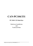
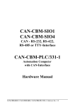
CAN - CSC595/2
CAN - PLC Interface Module
for
S5-90U, S5-95U and S5-100U
Hardware Manual
CAN-CSC595/2 Hardware Rev. 1.4
NOTE
The information in this document has been carefully checked and is believed to be entirely reliable. esd
makes no warranty of any kind with regard to the material in this document, and assumes no
responsibility for any errors that may appear in this document. esd reserves the right to make changes
without notice to this, or any of its products, to improve reliability, performance or design.
esd assumes no responsibility for the use of any circuitry other than circuitry which is part of a product
of esd gmbh.
esd does not convey to the purchaser of the product described herein any license under the patent rights
of esd gmbh nor the rights of others.
esd electronic system design gmbh
Vahrenwalder Str. 205
D-30165 Hannover
Germany
Tel:
Fax:
E-mail:
Internet:
+49-511-372-980
+49-511-633-650
[email protected]
http://www.esd-electronics.com
CAN-CSC595/2 Hardware Rev. 1.4
Document file:
I:\TEXTE\DOKU\MANUALS\CAN\CSC595.2\CSC0514H.EN6
Date of print:
16.11.98
PCB version:
CSC505-2
Changes in the chapters
The changes in the user’s manual listed below affect changes in the hardware as well as changes in the
description of the facts only.
Chapter
-
Changes versus previous version
First English version.
Technical details are subject to change without notice.
CAN-CSC595/2 Hardware Rev. 1.4
CAN-CSC595/2 Hardware Rev. 1.4
Contents
Page
1. Overview . . . . . . . . . . . . . . . . . . . . . . . . . . . . . . . . . . . . . . . . . . . . . . . . . . . . . . . . . . . . . . . . .
1.1 Module Description . . . . . . . . . . . . . . . . . . . . . . . . . . . . . . . . . . . . . . . . . . . . . . . . . . .
1.2 Front-Panel View With LEDs- and Connectors . . . . . . . . . . . . . . . . . . . . . . . . . . . . . .
1.3 Summary of Technical Data . . . . . . . . . . . . . . . . . . . . . . . . . . . . . . . . . . . . . . . . . . . . .
1.3.1 General Technical Data . . . . . . . . . . . . . . . . . . . . . . . . . . . . . . . . . . . . . . . . .
1.3.2 CAN-Interfaces of the CSC595/2 . . . . . . . . . . . . . . . . . . . . . . . . . . . . . . . . . .
1.3.3 PLC Unit . . . . . . . . . . . . . . . . . . . . . . . . . . . . . . . . . . . . . . . . . . . . . . . . . . . .
1.4 Software Support . . . . . . . . . . . . . . . . . . . . . . . . . . . . . . . . . . . . . . . . . . . . . . . . . . . . .
1.5 Order Information . . . . . . . . . . . . . . . . . . . . . . . . . . . . . . . . . . . . . . . . . . . . . . . . . . . .
3
3
4
5
5
6
7
7
9
2. Installation Notes . . . . . . . . . . . . . . . . . . . . . . . . . . . . . . . . . . . . . . . . . . . . . . . . . . . . . . . . . .
2.1 Installing the CSC595/2 Module into a SIMATIC-Automation Device . . . . . . . . . . . .
2.2 Connecting a Terminal . . . . . . . . . . . . . . . . . . . . . . . . . . . . . . . . . . . . . . . . . . . . . . . .
2.2.1 Terminal . . . . . . . . . . . . . . . . . . . . . . . . . . . . . . . . . . . . . . . . . . . . . . . . . . .
2.2.2 PC or Laptop with Terminal Program . . . . . . . . . . . . . . . . . . . . . . . . . . . . .
11
11
12
12
12
3. Component Print, Jumpers and Coding Switches . . . . . . . . . . . . . . . . . . . . . . . . . . . . . . . .
3.1 Component Print . . . . . . . . . . . . . . . . . . . . . . . . . . . . . . . . . . . . . . . . . . . . . . . . . . . .
3.2 Default Setting of Bridges and Coding Switches . . . . . . . . . . . . . . . . . . . . . . . . . . . . .
3.3 Description of Bridges and Coding Switches . . . . . . . . . . . . . . . . . . . . . . . . . . . . . . .
3.3.1 Operation of the 82527 with 10 MHz or 20 MHz (S202) . . . . . . . . . . . . . . .
3.3.2 Connection of Tx-signal of CAN controller 82527 to CAN interface
(S203) . . . . . . . . . . . . . . . . . . . . . . . . . . . . . . . . . . . . . . . . . . . . . . . . . . . . .
3.3.3 Activating the Bootstrap Loader (SL3) . . . . . . . . . . . . . . . . . . . . . . . . . . . .
3.3.4 Setting the Module No. via Coding Switch S301 . . . . . . . . . . . . . . . . . . . . .
13
13
15
16
16
4. Description of the Units . . . . . . . . . . . . . . . . . . . . . . . . . . . . . . . . . . . . . . . . . . . . . . . . . . . . .
4.1 PLC-Bus Interface . . . . . . . . . . . . . . . . . . . . . . . . . . . . . . . . . . . . . . . . . . . . . . . . . . .
4.2 CAN Bus Interface . . . . . . . . . . . . . . . . . . . . . . . . . . . . . . . . . . . . . . . . . . . . . . . . . . .
4.2.1 Bit Rate . . . . . . . . . . . . . . . . . . . . . . . . . . . . . . . . . . . . . . . . . . . . . . . . . . . .
4.2.2 Transmit and Receive Circuit of the CAN-Interface (Physical Layer) . . . . . .
4.3 Specification of the Serial Interface . . . . . . . . . . . . . . . . . . . . . . . . . . . . . . . . . . . . . .
4.4 LED Display . . . . . . . . . . . . . . . . . . . . . . . . . . . . . . . . . . . . . . . . . . . . . . . . . . . . . . .
19
19
20
20
20
21
22
5. Appendix . . . . . . . . . . . . . . . . . . . . . . . . . . . . . . . . . . . . . . . . . . . . . . . . . . . . . . . . . . . . . . . .
5.1 Connector Assignments . . . . . . . . . . . . . . . . . . . . . . . . . . . . . . . . . . . . . . . . . . . . . . .
5.1.1 PLC-Bus Connector P301 . . . . . . . . . . . . . . . . . . . . . . . . . . . . . . . . . . . . . .
5.1.2 Connector of CAN Bus Interface P3 (9-pin DSUB Male) . . . . . . . . . . . . . .
5.1.3 Serial Interface RS-232 at P2 (9-pin DSUB Female) . . . . . . . . . . . . . . . . . .
5.1.4 Connection Lines for CSC595/2 to PC (RS-232 Interface) . . . . . . . . . . . . . .
5.2 Circuit Diagrams . . . . . . . . . . . . . . . . . . . . . . . . . . . . . . . . . . . . . . . . . . . . . . . . . . . .
23
23
23
24
25
26
27
16
17
18
6. Correctly Wiring Electrically Insulated CAN Networks . . . . . . . . . . . . . . . . . . . . . . . . . . . 29
CAN-CSC595/2 Hardware Rev. 1.4
1
2
CAN-CSC595/2 Hardware Rev. 1.4
Overview
1. Overview
1.1 Module Description
Status LED
Configuration
Switch
RS232
DSUB9
RS232
Interface
+5V=
Status
DC/DC
CAN Bus
DSUB9
Phys.
CAN
Layer
CAN
µC
C167
PLC
Interface
PLC Bus
+5V=
electrical isolation
Option:
CAN
SRAM
FLASH
PROM
Intel
82527
Fig. 1.1.1: Block-circuit diagram of the CSC595/2
By means of the communication processor CAN-CSC595/2 SIEMENS PLCs of S5-90U, S5-95U or
S5-100U and esd-CAN-I/O modules or other CAN participants can be directly linked.
The module guarantees complete transparency of process data to the PLC programmer. No further
function or data components are required so that PLC programs can be run as usual.
The CAN-CSC595/2 uses the high performance microcontroller C167C with integrated CANcontroller and guarantees a bit rate of 1 Mbit/s without data loss even when the C167C is running as a
high-level-protocol master.
The physical CAN-layer corresponds to ISO 11898. Like all CAN-identifiers, the bit rate can be set via
the local RS-232 interface by means of the software.
This and other modules can be configured via the RS-232 interface. An automatic configuration of
other modules (after cold start) is also possible. The settings are stored into the local EEPROM.
The module is shipped in a plastic case which is compatible to SIEMENS S5 devices.
CAN-CSC595/2 Hardware Rev. 1.4
3
Overview
1.2 Front-Panel View With LEDs- and Connectors
CAN
P3 (9-pole DSUB Male):
CAN Bus Connector (ISO 11898)
State LED and Code Pin SL3
status
ID
RS-232
HEX Switch S301:
Module no.
P2 (9-pole DSUB Female):
Serial Interface (RS232)
CSC595/2
CAN
esd gmbh Hannover
4
CAN-CSC595/2 Hardware Rev. 1.4
Overview
1.3 Summary of Technical Data
1.3.1 General Technical Data
RS-232 interface
RS-232C interface at 9-pin female DSUB as input and
configuration interface and for loading new S-records for
software updates of the FLASH EPROM
Temperature range
0...50EC ambient temperature
Humidity
max. 90%, non-condensing
Power supply
CAN-module
fed via PLC bus,
nominal voltage 9V ±10%,
current (typical, at 20EC):
ca. 200 mA (without CAN-controller 82527)
Connectors
P301
P2 (DSUB9/female)
P3 (DSUB9/male)
Case
Siemens PLC-module case,
compatible to SIMATIC S5 bus module
Weight
ca. 250 g
-
PLC connection
RS-232 interface
CAN bus interface
Table 1.3.1: General data of the CSC595/2
CAN-CSC595/2 Hardware Rev. 1.4
5
Overview
1.3.2 CAN-Interfaces of the CSC595/2
Number of CAN-interfaces
one interface at connector P3
Controller components
C167 and 82527(option)
Use of the optional second
controller
reception and evaluation of RTR frames
CAN-identifiers
programmable via CAN- or RS232 interface
esd-module No.
can be set via coding switch in front panel or programmed via
CAN- or RS-232 interface
I²C-EEPROM
for storing the parameters
Physical layer
physical layer in accordance with ISO 11898, transmission rate
programmable from 10 kbit/s to 1 Mbit/s
Electrical insulation of the
CAN-interfaces from other units
insulation via optical couplers and DC/DC-converters
in accordance with German VDE regulation 0110b §8,
isolation group C and installation into cubicle): 300 V(DC),
250 V(AC)
Table 1.3.2: CAN-interfaces of the CSC595/2
6
CAN-CSC595/2 Hardware Rev. 1.4
Overview
1.3.3 PLC Unit
PLC link
compatible PLC units:
SIEMENS S5-90U
SIEMENS S5-95U
SIEMENS S5-100U
SIEMENS S5-102U
SIEMENS S5-103U
SIEMENS ET-100
Monitoring mode
monitoring the PLC bus:
transmission of all PLC data to the CAN bus
Table 1.3.3: PLC unit
1.4 Software Support
The complete EPROM-resident CAN-communication firmware for operating the CSC595/2 module is
contained in the product package. The software will be explained in the second part of the manual.
CAN-CSC595/2 Hardware Rev. 1.4
7
8
CAN-CSC595/2 Hardware Rev. 1.4
Order Information
1.5 Order Information
Type
Features
Order No.
interface CAN/Siemens S5-SPS
CAN-CSC595-2
product package:
device with CAN-controller C167 (82527 not
mounted) with plastic case, coding pin for bootstrap
loader, software and hardware manual
C.2902.02
CAN-CSC595/2-SDS
option: SDS master firmware
C.2902.50
CAN-CSC595/2-CoS
option: CANopen slave firmware
C.2902.52
CAN-CSC595/2-CoM
option: CANopen master firmware
C.2902.54
CAN-CSC595/2-MD
German manual
1*)
C.2902.20
CAN-CSC595/2-ME
English manual
1*)
C.2902.21
1*) If ordered together with the module, the manual is free of charge.
Table 1.5.1: Order information
CAN-CSC595/2 Hardware Rev. 1.4
9
10
CAN-CSC595/2 Hardware Rev. 1.4
Installation
2. Installation Notes
2.1 Installing the CSC595/2 Module into a SIMATIC-Automation Device
Please read the instructions in the SIMATIC-S5 manual carefully before taking the SIMATIC-S5
automation device into operation! The following steps relate only to the installation of the CSC595/2
module.
Way of procedure:
1.
Switch off (disconnect) the power supply of the SIMATIC central extension devices and of the
signal feeder and signal receiver.
2.
Select a free stack in the central device, plug CSC595/2 to board carrier of the SIMATIC and fix
by means of the recess screw accessible in the front panel.
3.
Connect CAN-interface.
The CAN-interface is connected via the 9-pin DSUB-connector in the front panel. Notes on wiring
the CAN-network can be taken from the chapter ‘Correctly Wiring Electrically Insulated
Networks’at the end of this manual.
4.
Connect terminal to RS232-interface.
You can either use a normal terminal (such as WYSE, FALCO) or a PC or Laptop with a terminal
program. The connection will be described separately in the following chapter ‘Connecting a
terminal’.
5.
Switch on central device, switch on the other CAN bus participants, switch on terminal (the
sequence is arbitrarily)
6.
If the driver software is already in the local Flash EPROM (default status when module is shipped),
the status LED of controller C167 (next to the coding connector) has to flash: green for 500 ms
and red for 100 ms. Doing this, the LED signalizes that the module status is OK and that the
module is operating by using the default parameters.
7.
Now the CSC595/2 module can be configured via a terminal. During the configuration various
parameters (such as bit rate, identifiers) can be changed. All configuration parameters can be
stored into the local EEPROM. The changed and stored parameters will only become active after
a RESET.
The configuration of the module will be described in the software manual. The you will also find a
complete list of default parameters with which the module is operating after being shipped.
CAN-CSC595/2 Hardware Rev. 1.4
11
Installation
2.2 Connecting a Terminal
The terminal is required to configure the CSC595/2 module. You can either use a normal terminal or
a PC with a terminal program. If users want to install new software updates themselves, a PC is
absolutely necessary.
The setting parameters of the interface (bit rate, etc.) Will be described in the chapter ‘Specification of
the serial Interface’, starting on page 21.
2.2.1 Terminal
During wiring the terminal should be switched off. The terminal is connected via the 9-pin female
DSUB connector (P2) in the front panel. The signal assignment has been chosen in a way that a
terminal can be directly connected without a null modem.
2.2.2 PC or Laptop with Terminal Program
During wiring the PC or Laptop should be switch off.
The port to which the module is connected during operation (configuration) depends on the terminal
program that is used. Normally, various ports are supported.
When connecting to a 9-pin mouse port a null modem has to be connected to the supply. If the PC or
Laptop is connected to a 25-pin DSUB-connector a null modem is not required. The signal assignment
of suitable connection lines will be listed in the appendix.
esd also offers manufactured connection cables with 9-pin connectors for which no null modem is
required.
12
CAN-CSC595/2 Hardware Rev. 1.4
Hardware Configuration
3. Component Print, Jumpers and Coding Switches
3.1 Component Print
Fig. 3.1.1: Position of configuration elements on the component layer of the PCB
CAN-CSC595/2 Hardware Rev. 1.4
13
Hardware Configuration
Fig. 3.1.2: Position of solder bridges on the bottom layer of the PCB
14
CAN-CSC595/2 Hardware Rev. 1.4
Hardware Configuration
3.2 Default Setting of Bridges and Coding Switches
The respective default setting of bridges, coding switches and of the plug contact at the time the board
is shipped, will be listed in the following figures.
Please refer to figure 3.1.1 for the position of the components on the top layer of the PCB. In the
following descriptions the components will be described as seen by the user with the board in a position
where the CAN bus connectors are pointing to the left.
The position of the solder bridges can be taken from figure 3.1.2. In the following descriptions the
solder bridges will be described as seen by the user with the board in a position where the CAN bus
connectors are pointing to the right (bottom layer view).
Summary of default settings when the module is shipped:
Solder bridge
Note:
Function
Setting
S200
memory capacity of SRAMs
256 kByte ( 2 x 128 kByte)
S202
operation of 82527 with
10 MHz or 20 MHz
82527 is pulsed with 20 MHz
S203
Tx-signal of the 82527 to CAN
interface
board without 82527: solder bridge open
board with 82527: bridge closed, i.e. Txsignal is connected to the CAN bus
interface
Solder bridge S200 will not be described again below, because the position of the bridge depends from the SMDmemory components (SRAMs) used. The SMD memories used are mounted at the factory and cannot be changed
afterwards. Therefore the user must not change the position of solder bridge S 200!
Plug contact/
coding switch
Plug contact
SL3
Function
Setting
activate bootstrap loader
not set, i.e. bootstrap loader is inactive
module No.
the module No. has always to be adjusted
to an available CAN network by the user,
therefore, there is no defined default
setting
Coding switch
S301
Table 3.2.1: Default setting of bridges and coding switches
CAN-CSC595/2 Hardware Rev. 1.4
15
Hardware Configuration
3.3 Description of Bridges and Coding Switches
3.3.1 Operation of the 82527 with 10 MHz or 20 MHz (S202)
By means of this solder bridge the pulse frequency of the 82527 controller can be set to 10 MHz or 20
MHz. When the module is shipped, the bridge is set to 20 MHz.
The position of this solder bridge is not to be changed by the user.
10 MHz
20 MHz
2
3
solder bridge open
1
solder bridge closed
to 82527
clock input
Example above: Setting of solder bridge for 20 MHz operation of controller 82527
3.3.2 Connection of Tx-signal of CAN controller 82527 to CAN interface (S203)
By means of this solder bridge the Tx-signal of the CAN controller 82527 is connected to the CAN
interface. The solder bridge is open, if the controller is not equipped.
The position of this solder bridge is not to be changed by the user.
from 82527
Tx-output
solder bridge open
2
1
solder bridge closed
to CAN
interface
Example above: CAN controller 82527 not equipped
16
CAN-CSC595/2 Hardware Rev. 1.4
Hardware Configuration
3.3.3 Activating the Bootstrap Loader (SL3)
In order to be able to download a software update via the serial interface into the local memory, the
bootstrap loader has to be enabled. It has been locked to prevent the local program code from being
overwritten accidentally.
In order to enable the bootstrap loader the coding pin, which is included in the product package, has to
be plugged into the socket SL3. The pin closes an internal contact and by doing so enables the
bootstrap loader. Now the loading procedure can be started via the operation software.
The coding pin makes a correct contact, when it is inserted as far as possible.
CAN-CSC595/2 Hardware Rev. 1.4
17
Hardware Configuration
3.3.4 Setting the Module No. via Coding Switch S301
The module No. with which the CSC595/2 module is selected via the CAN bus when operating by
means of the default parameters, consists of 8 bits. The module No. is required for the firmware to
identify the module.
By means of the four pin coding switch S301 in the front panel bits 0 to 3 of the CAN-module No. are
set. Bits 4 to 7 of the module No. have been fixed to ‘0'.
The assignment of coding switch position to module No. is therefore as follows:
Coding switch
position
Module-No. bit
[HEX]
0 (*)
1
2
:
E
F
00 (*)
01
02
:
0E
0F
Table 3.3.4: Assignment of coding switch position to module No.
(*) If the coding switch is set to ‘00' and a RESET is triggered (via Power Down), the module keeps
on operating by means of the default parameters after being switched on again. All previously changed
parameters are lost, even if they had been stored into the local I²C-EEPROM.
When the module is operating via the default parameters, the module No. which has been set at the
coding switch is active. The complete 8-bit module No. can be freely programmed via the firmware.
The programmed module No. replaces the module No. set via the coding switch immediately.
Programming the module No. will be described in the software manual of this module.
Attention: It is not possible to set and save new parameters of the module, while the coding
switch is set to ‘0’! This happens because, after a reset, that is necessary after the
programming of the module the new parameters will be overwriten by the default
parameters.
The setting of the coding switch at the moment the module is shipped has bot been determined, because
the user has to synchronize it with other module numbers in the CAN-network.
18
CAN-CSC595/2 Hardware Rev. 1.4
PLC-Interface
4. Description of the Units
4.1 PLC-Bus Interface
The CSC595/2 module has a PLC-interface which has been designed for the connection to Siemens
SIMATIC-S5 units. The interface is controlled by programmable logical components. The transmit and
receive data is buffered into SRAM memories. The following figure represents the structure of the
interface control.
P301
PLC-connector
U1
4043
Data OUT
+9V
2
VCC
S1
Q1
GND
EN
Data IN
3
4
1N4148
STST
13
INIT
9
11
SCLK
12
ENABLE*
14
15
U2
4010
1
5
GND
6
Fig. 4.2.1: Block-circuit diagram of the PLC-interface control
CAN-CSC595/2 Hardware Rev. 1.4
19
CAN-Interface
4.2 CAN Bus Interface
4.2.1 Bit Rate
The transmission speed of the CAN-interface can be varied between 10 kbit/s and 1.0 Mbit/s. The bit
rate is set by means of the local software. Further information on this can be taken from the software
manual of this module.
4.2.2 Transmit and Receive Circuit of the CAN-Interface (Physical Layer)
The C167C is used as a CAN-controller. The physical interface of the CAN bus is in accordance with
the ISO 11898 norm. The Si9200 or the 82C250 are used as CAN bus transceivers in the module. The
CAN-interface is supplied with power from the local +5V supply voltage by a DC/DC-converter. The
signals to the CAN bus are electrically insulated by optical couplers.
Notes on the wiring of the CAN-network:
The reference potential of the CAN bus (CAN_GND) has to be connected to the earth potential at
exactly one point in the CAN-network.
DCDC210
S7U-0505
VCC
+
5V
GND
5V
-
+5V
+
-
CAN_GND
RN201:B
CAN_TX
CAN_RX
U210
HCPL7101
U200
74HC08
&
Tx
VCCin
IN
to controller C167C
+5V
VCCout
ENABLE
GNDin
GNDout
TX0
RX0
to controller 82527
Rx
U211
HCPL7101
VCCout
OUT
+5V
VDD
RN201:C
VCC
P3
9-pole DSUB
U212
Si9200/
82C250
OUT
+5V
CAN_GND
TX
BUSL
CAN_L
RX
BUSH
CAN_H
GND
VCCin
IN
CAN transceiver
CAN_GND
3
2
7
6
ENABLE
GNDout
GNDin
optocoupler
+5V, VCC, GND, CANGND...
CAN_TX, CAN_RX...
TX0, RX0...
CAN_L, CAN_H...
Fig. 4.3.1:
local supply voltages
signals of CAN-controller C167C (U201)
signals of the optional CAN-controller 82527 (U205)
CAN bus signal lines
Functional circuit diagram of the CAN bus interface when using the interface
components Si9200 or 82C250
The connector assignment can be taken from the appendix.
20
CAN-CSC595/2 Hardware Rev. 1.4
RS-232 Interface
4.3 Specification of the Serial Interface
The RS-232 interface is specified as follows:
Parameters
Settings
baud rate
19200 baud
data bits
8 bits/character
stop bits
1 stop bit
parity bit
no parity
handshake
no handshake
(or, if this cannot be set: XON/XOFF)
Table 4.4.1: Parameters of the serial interface
The PC or terminal connected has to be set to the values specified above.
The connector assignment of the interface at P2 can be taken from the appendix.
CAN-CSC595/2 Hardware Rev. 1.4
21
LED Displays
4.4 LED Display
The status LED is next to the bootstrap plug.
Meaning of the LED status
LED status
constantly green
LED flashes:
short green,
short red
module is in RESET
status
module is in
bootstrap mode
module is in ‘normal’
operation
-
-
General status of the
nodule is OK
-
-
EEPROM error
-
Displaying the
bootstrap mode
-
-
-
Default status
(module is operating via
default parameters)
-
-
Module has been
configured as a CANopen
master, but the CANopen
network has not yet
started
Module is in RESET
-
-
(approx. 100 ms green, 100 ms red)
LED flashes:
short green,
short red
(approx. 200 ms green, 200 ms red)
LED flashes:
long green,
short red
(approx. 500 ms green, 100 ms red)
LED flashes:
short green,
short red,
short off
(330 ms green, 330 ms red, 330 ms off)
LED off
-...
22
This combination of operating status of the module and LED status does not exist.
CAN-CSC595/2 Hardware Rev. 1.4
Connector Assignment
5. Appendix
5.1 Connector Assignments
5.1.1 PLC-Bus Connector P301
Pin
Signal
1
2
3
4
5
6
7
8
9
10
11
12
13
14
15
GND
+9V
Data OUT
Data IN
GND
GND
INIT
SCLK
ENABLE*
STST-Bus
PE
PE
+9V, GND......
voltage supply
Data IN,
Data OUT......
data lines
STST-Bus......
start/stop signal of control unit
INIT..........
signal for initialisation sequence
SCLK..........
synchronous shift pulse
ENABLE*.......
enable input for bus
PE............
protection earth connection
'-'...........
not connected
CAN-CSC595/2 Hardware Rev. 1.4
23
Connector Assignment
5.1.2 Connector of CAN Bus Interface P3 (9-pin DSUB Male)
Pin Position:
Pin Assignment:
Signal
Pin
CAN_GND
6
CAN_H
7
reserved
8
reserved
9
Signal
1
reserved
2
CAN_L
3
CAN_GND
4
reserved
5
reserved
9-pin male DSUB connector
Signal Description:
CAN_L, CAN_H ... CAN-signal lines
CAN_GND ...
reference potential of the local CAN-physical layer
reserved ...
pins which are reserved for future applications
24
CAN-CSC595/2 Hardware Rev. 1.4
Connector Assignment
5.1.3 Serial Interface RS-232 at P2 (9-pin DSUB Female)
Pin Position:
Pin Assignment:
Signal
Pin
-
1
RxD
2
TxD
3
DTR
4
Signal
6
-
7
-
8
-
9
-
GND
5
9-pin female DSUB connector
Signal Description:
TxD ...
signal line: data output of the CSC595/2
RxD ...
signal lines: data input of the CSC595/2
DTR ...
handshake signal (output)
GND ...
reference potential
'-' ...
not connected
CAN-CSC595/2 Hardware Rev. 1.4
25
Connector Assignment
5.1.4 Connection Lines for CSC595/2 to PC (RS-232 Interface)
The following two figures show the required assignment for two RS-232 connection lines between PC
and CSC595/2.
Adapter cable 9-pin DSUB female to 9-pin DSUB male
1,5 m
P1
DSUB female
9-pole
5
4
9
3
8
2
7
1
1
6
2
6
3
7
4
5
8
P2
DSUB male
9-pole
9
P1:
P2:
(PC)
(CSC5x5)
1
1
RxD
2
TxD
3
4
2
RxD
3
TxD
4
GND
5
5
6
6
7
7
8
8
9
9
GND
local signal
names used
at CSC5x5
module
Adapter cable 25-pin DSUB female to 9-pin DSUB male
1,5 m
P1
DSUB female
25-pole
13 12 11 10
9
8
7
6
5
4
3
2
25 24 23 22 21 20 19 18 17 16 15 14
1
1
2
6
3
7
4
8
5
9
P1:
P2:
(PC)
(CSC5x5)
1
2
3
1
TxD
RxD
2
RxD
3
TxD
4
4
5
5
6
6
7
8
P2
DSUB male
9-pole
GND
7
GND
local signal
names used
at CSC5x5
module
8
9
25
26
CAN-CSC595/2 Hardware Rev. 1.4
Circuit Diagrams
5.2 Circuit Diagrams
CAN-CSC595/2 Hardware Rev. 1.4
27
28
CAN-CSC595/2 Hardware Rev. 1.4
Wiring
6. Correctly Wiring Electrically Insulated CAN Networks
Generally all instructions applying for wiring regarding an electromagnetic compatible installation,
wiring, cross sections of wires, material to be used, minimum distances, lightning protection, etc. have
to be followed.
The following general rules for the CAN wiring must be followed:
1.
A CAN net must not branch (exception: short dead-end feeders) and has to be
terminated by the wave impedance of the wire (generally 120 S ±10%) at both
ends (between the signals CAN_L and CAN_H and not at GND)!
2.
A CAN data wire requires two twisted wires and a wire to conduct the reference
potential (CAN_GND)!
For this the shield of the wire should be used!
3.
The reference potential CAN_GND has to be connected to the earth potential (PE)
at one point. Exactly one connection to earth has to be established!
4.
The bit rate has to be adapted to the wire length.
5.
Dead-end feeders have to kept as short as possible (l < 0.3 m)!
6.
When using double shielded wires the external shield has to be connected to the
earth potential (PE) at one point. There must be not more than one connection to
earth.
7.
A suitable type of wire (wave impedance ca. 120 S ±10%) has to be used and the
voltage loss in the wire has to be considered!
8.
CAN wires should not be laid directly next to disturbing sources. If this cannot be
avoided, double shielded wires are preferable.
Wire structure
Signal assignment of wire and connection of earthing and terminator
CAN wire with connectors
DSUB9 connector
(female or male)
pin designation
CAN_H
CAN_GND
120 Ohm
CAN_L
1
2
3
4
5
6
7
8
9
connector case
DSUB9 connector
(female or male)
pin designation
CAN_GND
(at wire shield)
n.c.
CAN_L
n.c.
n.c.
n.c.
n.c.
n.c.
n.c.
CAN_H
n.c.
n.c.
n.c.
n.c.
n.c.
n.c.
n.c.
n.c. = not connected
1
2
3
4
5
6
7
8
9
connector case
120 Ohm
Shielded wire with
transposed wires
earth (PE)
Fig.: Structure and connection of wire
CAN-CSC595/2 Hardware Rev. 1.4
29
Wiring
Cabling
• for devices which have only one CAN connector use T-connector and dead-end feeder (shorter than
0.3 m) (available as accessory)
CAN
Board
e.g. PCI/331,
ISA/331,
VME-CAN2, etc.
Net 1
Connecting
CAN_GND to
Protective Conductor PE
PE
Terminator
with PE Connector
CAN_H
Female Connector
CAN_L
Male Connector
CAN_GND
Male Terminator
Female Terminator
T-Connector
Net 2
l < 0,3 m
T-Connector
Terminator
l < 0,3 m
CAN
Module
CDIO16/16
CAN
Module
CMIO
CAN
Module
CAI810
CAN-SPS
Interface
CSC595/2
or
CAN-PC Board
CAN
Module
CDMS4
Fig.: Example for correct wiring (when using single shielded wires)
Terminal Resistance
•
use external terminator, because this CAN later be found again more easily!
•
9-pin DSUB terminator with male and female contacts and earth terminal are available as
accessories
Earthing
•
CAN_GND has to be conducted in the CAN wire, because the individual esd modules are
electrically insulated from each other!
•
CAN_GND has to be connected to the earth potential (PE) at exactly one point in the net!
•
each CAN user without electrically insulated interface works as an earthing, therefore: do not
connect more than one user without potential separation!
•
Earthing CAN e.g. be made at a connector
30
CAN-CSC595/2 Hardware Rev. 1.4
Wiring
Wire Length
•
Optocouplers are delaying the CAN signals. By using fast optocouplers and testing each board
at 1 Mbit/s, however, esd CAN guarantee a reachable length of 37 m at 1 MBit/s for most esd
CAN modules within a closed net without impedance disturbances like e.g. longer dead-end
feeders. (Exception: CANbloc-Mini-DIO8 and -AI4, this modules work only up to 10 m with
1 Mbit/s)
Bit rate
[kbit/s]
Typical values of reachable
wire length with esd
interface lmax [m]
CiA recommendations
(07/95) for reachable wire
lengths lmin [m]
37
59
80
130
180
270
420
570
710
1000
1400
2000
3600
5400
7300
25
50
100
250
500
650
1000
2500
5000
1000
800
666.6
500
333.3
250
166
125
100
66.6
50
33.3
20
12.5
10
Table: Reachable wire lengths depending on the Bit rate when using esd-CAN interfaces
Examples for Suitable Types of Wire
Manufacturer
Type of wire
U.I. LAPP GmbH & Co. KG
Schulze-Delitzsch-Straße 25
70565 Stuttgart / Germany
UNITRONIC ®-BUS LD,
UNITRONIC ®-BUS FD P LD
metrofunk
KABEL-UNION GmbH
Postfach 410109
12111 Berlin / Germany
LiYCY 2 x 0.38 mm², LiYCY 2 x 0.5 mm²,
LiYCY 2 x 0.75 mm², LiYCY 2 x 1.0 mm²,
1P x AWG 22 C, 1P x AWG 20 C
Alcatel Kabelmetal
Kabelkamp 20
30179 Hannover / Germany
DUE 4401, DUE 4001, DUE 4402
CAN-CSC595/2 Hardware Rev. 1.4
31