1
Embedded Solutions
20DC01-00 E4 – 2011-01-26
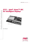
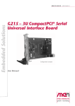
DC1 – Rugged Display
Computer
Configuration example
User Manual
®
Introduction to the DC1 – Rugged Display Computer
Introduction to the DC1 – Rugged Display Computer
The display computer DC1 is a rugged, fanless and maintenance-free panel PC for
harsh, mobile and mission-critical applications in transportation, avionics, medical
engineering and industrial automation. Its robust stainless enclosure is protected
against violent impacts and designed for a safeguarded use in direct contact with
humans, e.g. for infotainment purposes in trains, public buses or airplanes.
The DC1 is controlled by the Intel® Atom™ Z530 running at 1.6 GHz. It comes with 1
GB of DDR2 SDRAM and 4 GB of USB-driven Flash disk. The standard interfaces
comprise 2 Fast Ethernet and 2 USB ports as well as four binary inputs (with a fifth used
for key input functionality). Its two Ethernet interfaces have switch functionality to
provide Ethernet connection to subsequent intelligent displays. A temperature sensor
monitors and controls the display.
All I/O signals are concentrated at the bottom side of the DC1. The whole unit can
be directly mounted to a VESA mount or side-by-side or back-to-back with a
second display.
The standard version of the DC1 complies with the EN 50155, class Tx railway
standard (prepared for coating). It is thus for example equipped with an internal 24
VDC nom. (14.4 to 33.6 V) wide-range power supply and able to operate in a -40 to
+70°C environment (+85°C for 10 minutes; -30 to +70°C for the display panel with
automatic switch-off at excess temperatures).
MEN Mikro Elektronik GmbH
20DC01-00 E4 – 2011-01-26
2
Technical Data
Technical Data
CPU
• Intel® Atom™ Z530
- 1.6 GHz processor core frequency
- 533 MHz system bus frequency
• Chipset
- Intel® system controller hub US15W
Display
•
•
•
•
•
•
•
•
•
Screen size: 15"
Resolution: 1024 x 768 (XGA) with aspect ratio 4:3
Luminance (cd/m2): 450 cd/m2
Contrast: 700 typ.
Viewing angle: 160°/160° (preferred viewing angle 6 o'clock)
Backlight with brightness control: 2 CCFL min. 50,000 h
Interface: LVDS
Visible display area: 305.4 x 229.3 mm
Monitored and controlled by a temperature sensor
- Display is turned off at extreme temperatures
Memory
• 1 GB DDR2 SDRAM system memory
- Soldered
- 533 MHz memory bus frequency
• 4 GB Flash
I/O
• All I/O available at bottom of housing
- Invisible from the front
- Recessed within the housing
• USB
- Two USB 2.0 host ports
- Accessible via Series A connectors
- UHCI implementation
- Data rates up to 480 Mbits/s
• Ethernet
- Two 10/100Base-T Ethernet channels
- Accessible via M12 connectors
- Switch functionality
• 5 binary inputs
- 1 for key input functionality
- 4 universal inputs, e.g. for geographical addressing
MEN Mikro Elektronik GmbH
20DC01-00 E4 – 2011-01-26
3
Technical Data
Board Management Control
•
•
•
•
•
•
•
•
Supervision of input and internal voltages
Supervision of CPU and display temperature
Control of power sequencing and reset behavior of the Intel® Atom™ CPU
Emergency shutdown in case of failure
Wake on Time
Watchdog functionality for CPU with clock generator
Buffer functionality for RTC and BIOS CMOS
Accessible via SMBus
Electrical Specifications
• Isolation voltage:
- 1,500V DC between isolation groups
• Power consumption:
- 20 W typ.
• Supply voltage:
- 24 VDC nom. (14.4..33.6 V) according to EN 50155
• Key input functionality
• External power supply unit:
- 100..240 VAC in, 24 VDC out
Mechanical Specifications
•
•
•
•
•
•
•
Dimensions: 360 mm x 284 mm x 55.1 mm
Weight: 5.2 kg
Display covered with laminated glass
Aluminum enclosure
Prepared for wall mounting
Front, sides and top protected according to IP54
Back and bottom protected according to IP21
MEN Mikro Elektronik GmbH
20DC01-00 E4 – 2011-01-26
4
Technical Data
Environmental Specifications
• Temperature range (operation):
- -30 to +70°C for the display panel
(with automatic switch-off at excess temperatures)
- -40 to +70°C, with up to 85°C for 10 minutes according to class Tx
(EN 50155), for the computer
- Conductive cooling
- Fanless operation
• Temperature range (storage): -40..+85°C
• Relative humidity (operation): max. 95% non-condensing
• Relative humidity (storage): max. 95% non-condensing
• Altitude: -300 m to + 3,000 m
• Shock: according to EN 50155 (10.2.11)
• Vibration: according to EN 50155 (10.2.11)
MTBF
• 36,130 h @ +40°C according to IEC/TR 62380 (RDF 2000)
Safety
• PCB manufactured with a flammability rating of 94V-0 by UL recognized manufacturers
• Insulation according to EN 50155 (10.2.9.1)
• Withstand voltage according to EN 50155 (10.2.9.1)
• No edges and burrs
• Temperature gradient between housing and environment smaller than 15°C
EMC
• Conforming to EN 50155, EN 50121-3-2/EN 61000-4-5
Software Support
• Windows® XP Embedded image included (120-day trial version)
• For more information on supported operating system versions and drivers see
online data sheet.
MEN Mikro Elektronik GmbH
20DC01-00 E4 – 2011-01-26
5
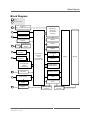
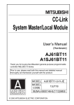
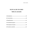
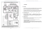
Block Diagram
Block Diagram
Options
R
R
Rear I/O Connector
Antenna (e.g. via SMA Connector)
R
R
PCI Express® Mini Card
for wireless functions
USB 2.0
USB 2.0
(Configurable Client)
USB 2.0
USB 2.0
USB 2.0
USB‐to‐Serial Bridge
R
COM
R
10/100Base‐T Ethernet
USB 2.0
R
10/100Base‐T Ethernet
‐
Intel® Atom™
Processor
and
Intel® System Controller Hub
2x USB 2.0
Display
Dual Ethernet Controller with Switch Functionality
System Memory
DDR2 SDRAM
R
HD Audio
Backlight Control
R
Power Supply
LVDS
Temperature
Sensor
SDVO
R
DVI‐D
MEN Mikro Elektronik GmbH
20DC01-00 E4 – 2011-01-26
Display
4GB Flash
SDVO‐to‐DVI Converter
SDVO‐to‐LVDS Converter
6
The DC Family: Flexible Concept – Easy Modification
The DC Family: Flexible Concept – Easy Modification
The DC1 is the first member of a whole family of display computers based on a
flexible modular configuration concept. The control electronics is directly attached
to the back of the screen, the standard display size being 15". Optional display and
housing sizes are 19", 17", and 12" (even smaller sizes possible on request). The
computer unit itself builds on the brand new Intel® ultra-mobile low-power
processor family starting with the Intel® Atom™ Z530 at 1.6 GHz or Z510 at 1.1
GHz. On request a serial interface can be added and the USB interfaces can be
individually configured up to a maximum of 5 ports (alternatively serial interfaces),
one of which a client port. A connection for a secondary display (on-board via
LVDS or external via DVI-D) can be made accessible, with then two displays able
to provide different and equal content at the same time. Additional I/O may
optionally comprise HD audio or field bus functions like IBIS. A PCI Express®
Mini card slot in combination with an external antenna can be used to incorporate
wireless functions like WIFI, WIMAX, GSM/GPRS, UMTS etc. The concept also
allows to use different input voltage ranges of the PSUs, for example 48 VDC nom.
(28.8 to 67.2V), 72 VDC nom. (43.2 to 100.8 V) or 110 VDC nom. (66 to 154 V)
for railway applications. With a typical power consumption of only 20 Watts for the
total system the design is always realized without fans, using conductive cooling
between the electronics and the display to spread the dissipated heat to the outside
of the housing. All electronic components are soldered to withstand shock and
vibration and prepared for conformal coating. The housing can be delivered vandalproof. This display computer series can be qualified according to the applicable
quality and security standards of the different markets it has been designed for.
MEN Mikro Elektronik GmbH
20DC01-00 E4 – 2011-01-26
7
Configuration Options
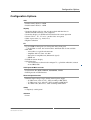
Configuration Options
CPU
• Intel® Atom™ Z530, 1.6 GHz
• Intel® Atom™ Z510, 1.1 GHz
Display
• Secondary display side-by-side or back-to-back with the first via
SDVO-to-LVDS converter (same computer)
• Secondary display via SVDO-to-DVI converter for remote operation
• Screen size 12", 15", 17" or 19" (smaller sizes on request)
• Other aspect ratios (e.g. 16:10, 15:9)
• Higher resolutions
I/O
• Up to 6 USB 2.0 host ports (or 5 host ports and 1 client port)
- If all USBs are used, the serial interface and Flash disk are not available
• HD audio
- Accessible via 9-pin D-sub connector
- Amplifier with 1.5 Vrms at 8 ohm
- Stereo line or amplified out (differential signal)
- SPDIF out
• DVI-D for remote display
• Serial interface
- 1 serial interface realized via SA-Adapter™, e.g. RS232 or RS422, isolated
or not, IBIS, GPS
PCI Express® Mini card slot
• For functions like WIFI, WIMAX, GSM/GPRS, UMTS
• PCI Express® or USB interface
Electrical Specifications
• Different input voltage ranges for the internal power supply
- 48 VDC nom. (28.8..67.2 V), 35W according to EN 50155
- 72 VDC nom. (43.2..100.8 V), 35W according to EN 50155
- 110 VDC nom. (66..154 V), 35W according to EN 50155
Safety
• Completely vandal-proof
Software
• Linux
MEN Mikro Elektronik GmbH
20DC01-00 E4 – 2011-01-26
8
Configuration Options
As the product concept is very flexible there are many other configuration
possibilities. Please contact our sales team if you do not find your required
function in the options.
For available standard configurations see online data sheet.
MEN Mikro Elektronik GmbH
20DC01-00 E4 – 2011-01-26
9
Product Safety
Product Safety
!
Handling Instructions
• Do not open the DC1. All repairs and changes to the system’s internals must be executed by authorized MEN personnel only.
• Do not drop the DC1. Although it is rugged, falls from a considerable height will
likely cause damage to the system.
• When mounting the DC1, read the instructions in this manual before consulting the
individual installation instructions for the mount used (see Chapter 2.1 Mounting
the DC1 using a Flat Display Panel Mounting Interface (VESA mount) on page
26).
• Do not install the DC1 near any heat sources (e.g. radiators, heat registers).
• Keep the DC1 away from liquids. Avoid exposure to dripping or splashing.
• Never handle the system or any connected cables with wet hands.
• Make sure that all peripheral devices are connected to the DC1 before connecting an external power supply and switching on the system.
• The heat sink on the rear of the DC1 may get warm after prolonged use. This is normal.
!
Electrostatic Discharge (ESD)
Computer boards and components contain electrostatic sensitive devices.
Electrostatic discharge (ESD) can damage components. To protect the board and
other components against damage from static electricity, you should follow some
precautions whenever you work on your computer.
• Power down and unplug your computer system when working on the inside.
• Hold components by the edges and try not to touch the IC chips, leads, or circuitry.
• Use a grounded wrist strap before handling computer components.
• Place components on a grounded antistatic pad or on the bag that came with the
component whenever the components are separated from the system.
• Store the board only in its original ESD-protected packaging. Retain the original
packaging in case you need to return the board to MEN for repair.
MEN Mikro Elektronik GmbH
20DC01-00 E4 – 2011-01-26
10
About this Document
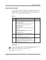
About this Document
This user manual describes the hardware functions of the board. It also provides
additional information for special applications and configurations of the board.
The manual does not include detailed information on individual components (data
sheets etc.). A list of literature is given in the appendix.
History
Edition
Comments
Date of Issue
E1
First edition
2008-08-06
E2
Major update of firmware section with final commands, removed SMBus On Acknowledge section
2008-12-19
Added information on
display operating tempe-rature/automatic switch-off
Corrected pinning of power supply connector
Removed mention of
second MAC address
Added chapter on the included Windows XP Embedded image
Standardized information regarding input voltage
ranges and serial interfaces
Corrected fuse type
Several minor corrections (incl. block diagram)
E3
Added information on Ethernet switch functionality
and audio interface
2008-10-27
Improved depiction of M12 connector
E4
Added GPS option
2011-01-26
Added warning regarding connection of both Ethernet ports to the same switch in powerless state
Consolidated Firmware Functions chapter, corrected
7-bit SMBus address of the PSU
Conventions
!
italics
bold
This sign marks important notes or warnings concerning proper functionality of the
product described in this document. You should read them in any case.
Folder, file and function names are printed in italics.
Bold type is used for emphasis.
MEN Mikro Elektronik GmbH
20DC01-00 E4 – 2011-01-26
11
About this Document
monospace
hyperlink
A monospaced font type is used for hexadecimal numbers, listings, C function
descriptions or wherever appropriate. Hexadecimal numbers are preceded by "0x".
Hyperlinks are printed in blue color.
The globe will show you where hyperlinks lead directly to the Internet, so you can
look for the latest information online.
IRQ#
/IRQ
Signal names followed by "#" or preceded by a slash ("/") indicate that this signal is
either active low or that it becomes active at a falling edge.
in/out
Signal directions in signal mnemonics tables generally refer to the corresponding
board or component, "in" meaning "to the board or component", "out" meaning
"coming from it".
Vertical lines on the outer margin signal technical changes to the previous edition of
the document.
MEN Mikro Elektronik GmbH
20DC01-00 E4 – 2011-01-26
12
About this Document
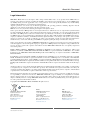
Legal Information
MEN Mikro Elektronik reserves the right to make changes without further notice to any products herein. MEN makes no
warranty, representation or guarantee regarding the suitability of its products for any particular purpose, nor does MEN assume
any liability arising out of the application or use of any product or circuit, and specifically disclaims any and all liability,
including without limitation consequential or incidental damages.
"Typical" parameters can and do vary in different applications. All operating parameters, including "Typicals" must be
validated for each customer application by customer's technical experts.
MEN does not convey any license under its patent rights nor the rights of others.
Unless agreed otherwise, MEN products are not designed, intended, or authorized for use as components in systems intended
for surgical implant into the body, or other applications intended to support or sustain life, or for any other application in which
the failure of the MEN product could create a situation where personal injury or death may occur. Should Buyer purchase or
use MEN products for any such unintended or unauthorized application, Buyer shall indemnify and hold MEN and its officers,
employees, subsidiaries, affiliates, and distributors harmless against all claims, costs, damages, and expenses, and reasonable
attorney fees arising out of, directly or indirectly, any claim of personal injury or death associated with such unintended or
unauthorized use, even if such claim alleges that MEN was negligent regarding the design or manufacture of the part.
Unless agreed otherwise, the products of MEN Mikro Elektronik are not suited for use in nuclear reactors and for application
in medical appliances used for therapeutical purposes. Application of MEN products in such plants is only possible after the
user has precisely specified the operation environment and after MEN Mikro Elektronik has consequently adapted and
released the product.
ESM™, MDIS™, MDIS4™, MENMON™, M-Module™, M-Modules™, SA-Adapter™, SA-Adapters™, UBox™ and
USM™ are trademarks of MEN Mikro Elektronik GmbH. PC-MIP® is a registered trademark of MEN Micro, Inc. and SBS
Technologies, Inc. MEN Mikro Elektronik®, ESMexpress® and the MEN logo are registered trademarks of MEN Mikro
Elektronik GmbH.
PowerPC® is a registered trademark of IBM Corp. Intel® Atom™ and Intel® Core™ are trademarks of Intel, Inc. Celeron®,
Intel®, Pentium® and Xeon® are registered trademarks of Intel, Inc. COM Express™ is a trademark of PCI Industrial
Computer Manufacturers Group. CompactPCI® is a registered trademark of PCI Industrial Computer Manufacturers Group.
Microsoft® and Windows® are registered trademarks of Microsoft Corp. Windows® Vista™ is a trademark of Microsoft Corp.
PCI Express® and PCIe® are registered trademarks of PCI-SIG. Phoenix® is a registered trademark of Phoenix Technologies
Ltd.
All other products or services mentioned in this publication are identified by the trademarks, service marks, or product names
as designated by the companies who market those products. The trademarks and registered trademarks are held by the
companies producing them. Inquiries concerning such trademarks should be made directly to those companies. All other brand
or product names are trademarks or registered trademarks of their respective holders.
Information in this document has been carefully checked and is believed to be accurate as of the date of publication; however,
no responsibility is assumed for inaccuracies. MEN Mikro Elektronik accepts no liability for consequential or incidental
damages arising from the use of its products and reserves the right to make changes on the products herein without notice to
improve reliability, function or design. MEN Mikro Elektronik does not assume any liability arising out of the application or
use of the products described in this document.
Copyright © 2011 MEN Mikro Elektronik GmbH. All rights reserved.
Please recycle
Germany
MEN Mikro Elektronik GmbH
Neuwieder Straße 5-7
90411 Nuremberg
Phone +49-911-99 33 5-0
Fax +49-911-99 33 5-901
E-mail [email protected]
www.men.de
MEN Mikro Elektronik GmbH
20DC01-00 E4 – 2011-01-26
France
MEN Mikro Elektronik SA
18, rue René Cassin
ZA de la Châtelaine
74240 Gaillard
Phone +33 (0) 450-955-312
Fax +33 (0) 450-955-211
E-mail [email protected]
www.men-france.fr
USA
MEN Micro, Inc.
24 North Main Street
Ambler, PA 19002
Phone (215) 542-9575
Fax (215) 542-9577
E-mail [email protected]
www.menmicro.com
13
Contents
Contents
1 System Overview . . . . . . . . . . . . . . . . . . . . . . . . . . . . . . . . . . . . . . . . . . . . . . .
1.1 Layout of the DC1 . . . . . . . . . . . . . . . . . . . . . . . . . . . . . . . . . . . . . . . .
1.2 External 100..240V AC Power Supply . . . . . . . . . . . . . . . . . . . . . . . .
1.3 Internal 24V DC Power Supply. . . . . . . . . . . . . . . . . . . . . . . . . . . . . .
1.4 Interfaces . . . . . . . . . . . . . . . . . . . . . . . . . . . . . . . . . . . . . . . . . . . . . . .
1.4.1
USB Interface . . . . . . . . . . . . . . . . . . . . . . . . . . . . . . . . . . . .
1.4.2
Ethernet Interface . . . . . . . . . . . . . . . . . . . . . . . . . . . . . . . . .
1.4.3
Binary Inputs. . . . . . . . . . . . . . . . . . . . . . . . . . . . . . . . . . . . .
1.4.4
DVI-D Interface (optional) . . . . . . . . . . . . . . . . . . . . . . . . . .
1.4.5
Serial interface (optional) . . . . . . . . . . . . . . . . . . . . . . . . . . .
1.4.6
HD Audio Interface (optional) . . . . . . . . . . . . . . . . . . . . . . .
1.4.7
Wireless interface (optional, e.g. SMA connector) . . . . . . . .
18
18
20
20
21
21
22
23
24
24
25
25
2 Getting Started . . . . . . . . . . . . . . . . . . . . . . . . . . . . . . . . . . . . . . . . . . . . . . . .
2.1 Mounting the DC1 using a Flat Display Panel
Mounting Interface (VESA mount). . . . . . . . . . . . . . . . . . . . . . . . . . .
2.2 Using the included External Power Supply . . . . . . . . . . . . . . . . . . . . .
2.3 Using a customized Power Supply . . . . . . . . . . . . . . . . . . . . . . . . . . .
2.4 Power Down . . . . . . . . . . . . . . . . . . . . . . . . . . . . . . . . . . . . . . . . . . . .
2.5 Installing Operating System and Driver Software. . . . . . . . . . . . . . . .
26
3 Firmware Functions . . . . . . . . . . . . . . . . . . . . . . . . . . . . . . . . . . . . . . . . . . . .
3.1 Onboard Microcontroller. . . . . . . . . . . . . . . . . . . . . . . . . . . . . . . . . . .
3.2 SMBus Functionality. . . . . . . . . . . . . . . . . . . . . . . . . . . . . . . . . . . . . .
3.2.1
SMBus Interface . . . . . . . . . . . . . . . . . . . . . . . . . . . . . . . . . .
3.2.2
Wake On Time. . . . . . . . . . . . . . . . . . . . . . . . . . . . . . . . . . . .
3.2.3
Watchdog. . . . . . . . . . . . . . . . . . . . . . . . . . . . . . . . . . . . . . . .
3.2.4
Status of Binary Inputs . . . . . . . . . . . . . . . . . . . . . . . . . . . . .
3.2.5
Key Input. . . . . . . . . . . . . . . . . . . . . . . . . . . . . . . . . . . . . . . .
3.2.6
Shutdown. . . . . . . . . . . . . . . . . . . . . . . . . . . . . . . . . . . . . . . .
3.2.7
Shutdown Delay . . . . . . . . . . . . . . . . . . . . . . . . . . . . . . . . . .
3.2.8
Voltage Supervision . . . . . . . . . . . . . . . . . . . . . . . . . . . . . . .
3.2.9
Temperature Supervision . . . . . . . . . . . . . . . . . . . . . . . . . . .
3.2.10 Display Backlight Power and Brightness Control . . . . . . . .
3.2.11 Optional Autonomous Brightness Control
with Photo Diode . . . . . . . . . . . . . . . . . . . . . . . . . . . . . . . . .
3.2.12 Miscellaneous Commands . . . . . . . . . . . . . . . . . . . . . . . . . .
26
26
26
27
27
28
28
29
29
29
30
31
31
31
32
34
34
35
36
36
4 Maintenance . . . . . . . . . . . . . . . . . . . . . . . . . . . . . . . . . . . . . . . . . . . . . . . . . . 37
4.1 Cleaning the Display . . . . . . . . . . . . . . . . . . . . . . . . . . . . . . . . . . . . . . 37
4.2 Fuse Protection . . . . . . . . . . . . . . . . . . . . . . . . . . . . . . . . . . . . . . . . . . 37
5 Appendix . . . . . . . . . . . . . . . . . . . . . . . . . . . . . . . . . . . . . . . . . . . . . . . . . . . . . 38
5.1 Literature and Web Resources . . . . . . . . . . . . . . . . . . . . . . . . . . . . . . . 38
MEN Mikro Elektronik GmbH
20DC01-00 E4 – 2011-01-26
14
Contents
5.2 Finding out the Display Computer’s Article Number, Revision
and Serial Number . . . . . . . . . . . . . . . . . . . . . . . . . . . . . . . . . . . . . . . . 38
MEN Mikro Elektronik GmbH
20DC01-00 E4 – 2011-01-26
15
Figures
Figure 1.
Figure 2.
Figure 3.
Figure 4.
Figure 5.
Figure 6.
MEN Mikro Elektronik GmbH
20DC01-00 E4 – 2011-01-26
The DC1 - front view . . . . . . . . . . . . . . . . . . . . . . . . . . . . . . . . . . . . . .
The DC1 - bottom view (shown with standard connectors only). . . . .
The DC1 - rear view . . . . . . . . . . . . . . . . . . . . . . . . . . . . . . . . . . . . . . .
Connectors at the bottom side of the DC1 . . . . . . . . . . . . . . . . . . . . . .
Microcontroller block diagram. . . . . . . . . . . . . . . . . . . . . . . . . . . . . . .
Label giving the board’s article number, revision
and serial number . . . . . . . . . . . . . . . . . . . . . . . . . . . . . . . . . . . . . . . . .
18
18
19
21
28
38
16
Tables
Table 1.
Table 2.
Table 3.
Table 4.
Table 5.
Table 6.
Table 7.
Table 8.
Table 9.
Table 10.
Table 11.
Table 12.
Table 13.
Table 14.
Table 15.
Table 16.
Table 17.
Table 18.
Table 19.
Table 20.
Table 21.
Table 22.
Table 23.
Table 24.
Table 25.
Table 26.
MEN Mikro Elektronik GmbH
20DC01-00 E4 – 2011-01-26
Pin assignment of the USB connectors. . . . . . . . . . . . . . . . . . . . . . . . .
Signal mnemonics of the USB connectors . . . . . . . . . . . . . . . . . . . . . .
Pin assignment of the Ethernet M12 connectors . . . . . . . . . . . . . . . . .
Pin assignment of the power supply/binary inputs
7W2 D-Sub connector . . . . . . . . . . . . . . . . . . . . . . . . . . . . . . . . . . . . .
Signal mnemonics of the binary inputs . . . . . . . . . . . . . . . . . . . . . . . .
Pin assignment of the DVI output . . . . . . . . . . . . . . . . . . . . . . . . . . . .
Signal mnemonics of the DVI output . . . . . . . . . . . . . . . . . . . . . . . . . .
Pin assignment of the HD audio interface . . . . . . . . . . . . . . . . . . . . . .
Signal mnemonics of the HD audio interface. . . . . . . . . . . . . . . . . . . .
SMBus commands for wake on time function . . . . . . . . . . . . . . . . . . .
SMBus commands XC02C_WOT_L / XC02C_WOT_H . . . . . . . . . .
SMBus commands for the watchdog function . . . . . . . . . . . . . . . . . . .
SMBus command XC02C_WDOG_TOUT . . . . . . . . . . . . . . . . . . . . .
SMBus commands for binary inputs status . . . . . . . . . . . . . . . . . . . . .
SMBus command for shutdown by software function . . . . . . . . . . . . .
SMBus commands for shutdown delay . . . . . . . . . . . . . . . . . . . . . . . .
SMBus command XC02C_STATUS . . . . . . . . . . . . . . . . . . . . . . . . . .
SMBus command XC02C_DOWN_DELAY . . . . . . . . . . . . . . . . . . .
SMBus command for Off delay function . . . . . . . . . . . . . . . . . . . . . . .
SMBus command XC02C_OFF_DELAY . . . . . . . . . . . . . . . . . . . . . .
SMBus command for Off acknowledge function. . . . . . . . . . . . . . . . .
SMBus command for voltage supervision function . . . . . . . . . . . . . . .
SMBus commands for temperature supervision. . . . . . . . . . . . . . . . . .
Temperature representation . . . . . . . . . . . . . . . . . . . . . . . . . . . . . . . . .
SMBus commands for display control . . . . . . . . . . . . . . . . . . . . . . . . .
SMBus commands for PSU ID and firmware revision number . . . . . .
21
21
22
23
23
24
24
25
25
29
29
30
30
31
31
32
32
32
33
33
33
34
35
35
36
36
17
System Overview
1
System Overview
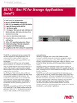
1.1
Layout of the DC1
Figure 1. The DC1 - front view
Figure 2. The DC1 - bottom view (shown with standard connectors only)
MEN Mikro Elektronik GmbH
20DC01-00 E4 – 2011-01-26
18
System Overview
Figure 3. The DC1 - rear view
MEN Mikro Elektronik GmbH
20DC01-00 E4 – 2011-01-26
19
System Overview
1.2
External 100..240V AC Power Supply
The DC1 usually comes with an external power supply (with a 100..240V AC to
24V DC converter) to power the system outside of custom installations (e.g. during
setup and testing). For more information see Chapter 2.2 Using the included
External Power Supply on page 26.
1.3
Internal 24V DC Power Supply
The DC1 usually comes with an internal 24VDC nom. (14.4 to 33.6V) wide-range
power supply. It is connected via a mixed 7W2 D-Sub connector that also provides a
binary input for key input functionality. Power supply units with other input voltage
ranges (up to 110V nom. for railway applications) are also available from MEN to
suit individual projects’ needs. Please refer to the Table 4, Pin assignment of the
power supply/binary inputs 7W2 D-Sub connector, on page 23 for further details.
MEN Mikro Elektronik GmbH
20DC01-00 E4 – 2011-01-26
20
System Overview
1.4
Interfaces
The DC1 offers a plethora of connections at the bottom side of the unit (from left to
right as depicted):
Figure 4. Connectors at the bottom side of the DC1
•
•
•
•
•
•
•
Power supply with 5 binary inputs (through mixed 7W2 D-Sub connector)
2x USB 2.0
2x Fast Ethernet
Serial interface (optional)
HD audio (optional)
DVI-D (optional)
Antenna connector (optional, e.g. SMA connector)
1.4.1
USB Interface
The DC1 comes with two USB 2.0 ports supporting data rates up to 480Mbits/s,
UHCI implementation and external PHY functions.
Table 1. Pin assignment of the USB connectors
1
2
3
4
1
+5V
2
USB_D-
3
USB_D+
4
GND
Table 2. Signal mnemonics of the USB connectors
Signal
Direction
+5V
out
+5 V power supply
GND
-
Digital ground
USB_D+, USB_D- in/out
MEN Mikro Elektronik GmbH
20DC01-00 E4 – 2011-01-26
Function
USB lines, differential pair
21
System Overview
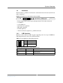
1.4.2
Ethernet Interface
The DC1 comes with two Fast Ethernet ports with switch functionality. They are
available through rugged M12 "D coding" female connectors of type Erni P/N
234041.
Both half and full duplex mode are supported. Switching functionality is provided
for forwarding of Ethernet frames to subsequent intelligent displays. The DC1 also
supports powerless forwarding of Ethernet frames: The unit’s onboard switch is
bypassed when the Ethernet circuit is not supplied with its intended voltage. Thus, a
switched off or defective DC1 unit does not interrupt the Ethernet traffic in a daisy
chain configuration.
!
Note that the two Ethernet ports are connected via a relay while the DC1 is in
powerless state, so connecting both to the same switch will likely jam the network.
Table 3. Pin assignment of the Ethernet M12 connectors
3
2
4
1
Pin
Name
Description
1
TX+
Transmitter positive output
2
RX+
Receiver positive input
3
TX-
Transmitter negative output
4
RX-
Receiver negative input
The Ethernet controller has its own EEPROM to store the MAC address etc.
!
The unique MAC address is set at the factory and should not be changed. Any
attempt to change this address may create node or bus contention and thereby render
the unit inoperable. The MAC address on the DC1 is:
• LAN0:
0x 00 C0 3A 85 xx xx
where "00 C0 3A" is the MEN vendor code, "85" is the MEN product code and
"xx xx" is the hexadecimal serial number of the DC1’s carrier board, e. g. "...
00 2A" for the serial number "000042".
Please note that due to the structure of the DC1, the serial number of the unit’s
carrier board is different from the serial number of the entire DC1 unit. For the
unit’s overall serial number please refer to Chapter 5.2 Finding out the Display
Computer’s Article Number, Revision and Serial Number on page 38.
MEN Mikro Elektronik GmbH
20DC01-00 E4 – 2011-01-26
22
System Overview
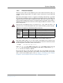
1.4.3
Binary Inputs
The mixed 7W2 D-Sub power supply connector of the DC1 provides five binary inputs.
The binary inputs are isolated from each other and the isolated system ground. The
input voltage range is from 0 V up to the input voltage. The nominal switching level
is 9 V. The current is 5 mA. This value is independent of the input voltage.
There are four inputs dedicated to the geographical addressing of the DC1 and one
key input. The state of the binary inputs can be read via the SMBus interface. See
Chapter 3.2.4 Status of Binary Inputs on page 31.
Table 4. Pin assignment of the power supply/binary inputs 7W2 D-Sub connector
A1
3
1
2
5
A2
1
POSITION_EXT[1]
2
POSITION_EXT[3]
3
PWR_ON_EXT
4
POSITION_EXT[2]
5
POSITION_EXT[4]
A1
I+24V
A2
IGND_3
Table 5. Signal mnemonics of the binary inputs
Signal
Function
PWR_ON_EXT
in
Key input
POSITION_EXT_[x]
in
Binary inputs for geographical adderssing
I+24V
in
+24V power supply
IGND_3
-
Analog ground
MEN Mikro Elektronik GmbH
20DC01-00 E4 – 2011-01-26
Direction
23
System Overview
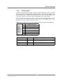
1.4.4
DVI-D Interface (optional)
The DC1 optionally offers a DVI-D connector that makes it possible to connect a
second display. The two displays can be used to show the same or different content
depending on the Windows XP Embedded display settings.
Table 6. Pin assignment of the DVI output
9
17
1
24
8
c3
c4
c1
c5
c2
17
TX0-
9
TX1-
1
TX2-
18
TX0+
10
TX1+
2
TX2+
19
GND
11
GND
3
GND
20
-
12
-
4
-
21
-
13
-
5
-
22
GND
14
DDCPOW
6
DDCL
23
TXC+
15
GND
7
DDCA
24
TXC-
16
DVIHP
8
-
C3
-
C1
-
C2
-
C5
C3
-
-
Table 7. Signal mnemonics of the DVI output
Signal
1
Direction
Function
DDCA
out
Display Data Channel data
DDCL
out
Display Data Channel clock
DDCPOW
out
Display Data Channel Power, +5V; currentlimited to 1.5A by a fuse1
DVIHP
in
DVI hot plug detect
GND
-
Digital ground
TX[0..2]+, TX[0..2]- out
Transmit data lines (TMDS), differential pairs
TXC+, TXC-
TX clocks (TMDS clock), differential pair
out
The DVI fuses used on the DC1 are PolyFuses and therefore need no maintenance
1.4.5
Serial interface (optional)
The Serial interface is an optional feature of the DC1 and is realized via an SAAdapter. You can use different types of SA-Adapters with the DC1, e.g. isolated and
non-isolated adapters for RS232 and IBIS master and slave interfaces. These
interfaces are accessible by means of a 9-pin D-Sub connector on the SA-Adapter
on the bottom side of the DC1. Another option is a GPS interface with a rugged
SMA connector.
!
Please note that SA-Adapters must be installed by authorized MEN personnel only.
Do not open the DC1!
MEN Mikro Elektronik GmbH
20DC01-00 E4 – 2011-01-26
24
System Overview
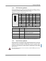
1.4.6
HD Audio Interface (optional)
The DC1 offers an optional HD audio output with an amplifier with 1.5 Vrms at 8
ohm via a 9-pin D-Sub connector. It provides both analog and digital audio.
Table 8. Pin assignment of the HD audio interface
9
6
5
1
9
AUDIO_IN_R
5
AUDIO_SPDIF
8
AUDIO_GND
4
AUDIO_IN_L
7
AUDIO_OUT_R+
3
AUDIO_OUT_R-
6
AUDIO_OUT_L-
2
AUDIO_GND
1
AUDIO_OUT_L+
Table 9. Signal mnemonics of the HD audio interface
Signal
Direction
Description
AUDIO_EXT_OUT_L±/R± out
Line out, left and right, differential signal
pairs
AUDIO_EXT_IN_L/R
in
Line in, left and right
AUDIO_EXT_GND
-
Analog ground
AUDIO_EXT_SPDIF
out
S/PDIF output
1.4.7
Wireless interface (optional, e.g. SMA connector)
A PCI Express Mini card can be used to incorporate wireless functions like WIFI,
WIMAX, GSM/GPRS or UMTS. In that case the DC1 is usually equipped with an
SMA antenna connector. The standard position for this connector is on the right side
at the bottom (other positions can be realized on request). A SIM card can be used
as the unit offers a SIM card slot inside.
!
Please note that PCI Express Mini cards and SIM cards must be installed by
authorized MEN personnel only. Do not open the DC1!
MEN Mikro Elektronik GmbH
20DC01-00 E4 – 2011-01-26
25
Getting Started
2
Getting Started
2.1
!
!
Mounting the DC1 using a Flat Display Panel Mounting
Interface (VESA mount)
The DC1 is designed for mounting using a Flat Display Mounting Interface
(commonly known as VESA mount). For the standard 15" DC1 the width and height
of the mounting hole pattern is 75x75 mm. Make sure to use four M6x1 10mm
screws to attach the DC1 to the VESA mount. Do not use the M4 screws that are
often included with VESA MIS-D 75 compliant mounts! Except for the
recommended screw size, follow the individual installation instructions for the
mount you are using.
Please note that depending on the size of the display used and the weight of the
system, different mounting hole patterns and sizes might apply for other models.
2.2
Using the included External Power Supply
The DC1 comes with an external power supply to allow for quick and easy setup
and testing. Simply attach the external power supply’s power cord to a standard
230V AC power outlet and the mixed 7W2 D-Sub plug to the power input of the
DC1. The DC1 will start up immediately, because the key input signal from the
external power supply is constantly active.
!
Make sure that all peripheral devices are connected to the DC1 before connecting
the external power supply!
If the external power supply remains active after a system shutdown, you can also
turn the DC1 on by Wake on time via the SMBus interface (see Chapter 3.2.2 Wake
On Time on page 29).
2.3
Using a customized Power Supply
When using a custom power supply soluton instead of the included external power
supply, you must be aware of the DC1’s key input functionality (see Chapter 3.2.5
Key Input on page 31). Simply supplying the internal 24VDC power supply with
power will not power up the system when there is no key input voltage present on
the binary input 3 of the power connector. To bypass the key input feature, connect
Vin with Keyin for a constantly active key input signal.
When the DC1 is connected to a customized power supply and supplied with 24V
DC, the system can be switched on in the following two ways:
• Key input (ignition key) via isolated binary input (see Chapter 3.2.5 Key Input
on page 31). The switching threshold is 9VDC.
• Wake on time via the SMBus interface (see Chapter 3.2.2 Wake On Time on
page 29).
!
Make sure that all peripheral devices are connected to the DC1 before switching on
the system!
MEN Mikro Elektronik GmbH
20DC01-00 E4 – 2011-01-26
26
Getting Started
2.4
Power Down
The DC1 can be switched off in the following three ways:
!
• Key input (ignition key) via isolated binary input. The system will shut down
without key input voltage (see Chapter 3.2.6.2 Shutdown by Key Input on page
32).
• Shutdown by application software: the shutdown can be signaled via an SMBus
command from application to host (see Chapter 3.2.6.1 Shutdown by Software
on page 31).
• Disconnecting the DC1 from any external power supply. Please note that Windows XP Embedded, the pre-installed operating system of the DC1, needs a controlled power down sequence. This means that using this method to power down
the DC1 can result in corrupted data. Make sure you shut down the operating
system before disconnecting any external power supply!
2.5
Installing Operating System and Driver Software
The DC1 comes with a 120-day trial version of Windows XP Embedded and all
necessary drivers pre-installed on its 4 GB USB-driven Flash disk. Please refer to
the respective software documentation for a detailed description and configuration
options.
During the first power up of the system, the First Boot Agent software will be
executed automatically. This will take approximately 45 minutes. No action on
behalf of the user is necessary at this time. The 120-day trial period starts the
moment the First Boot Agent finishes setting up the system.
Please note that the battery-powered internal clock of the DC1 is used to determine
how much of the trial period remains.
The following events can cause the trial period to end prematurely:
!
• The BIOS time is modified.
• The CPU is separated from the carrier board (the battery is located on the carrier
board, so the CPU’s internal clock is no longer buffered).
• A BIOS update has unforeseen side-effects.
Should any of this happen and render the trial version of Windows XP Embedded
unusable prematurely, please contact MEN.
A board support package (BSP) containing all the necessary, hardware-specific
components to create an individualized Windows XP Embedded will be made
available on MEN’s website. A complete log of the standard Windows XP
Embedded image used on the DC1 is available from MEN on request.
MEN Mikro Elektronik GmbH
20DC01-00 E4 – 2011-01-26
27
Firmware Functions
3
Firmware Functions
The functions of the XC02BC board controller described in the following chapter
depend on the firmware. This user manual describes the functions as realized in the
current MEN standard firmware. To access the functions described below from own
applications, MEN provides the Windows Installset 13XM01-77 and an OSindependent MDIS driver package, 13XC02-06. Please also refer to the general
MDIS documentation for details.
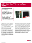
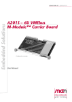
3.1
Onboard Microcontroller
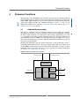
The DC1 is equipped with an intelligent internal power supply. Its onboard
microcontroller is used as a control and supervision device of the DC/DC converter,
the binary inputs of the DC1, its temperature and its display. Additionally, it is used
as a watchdog for the CPU and the microcontroller itself. The microcontroller is
connected to the CPU via SMBus. It is able to keep the power supply active even if
the external on/off-signal goes inactive. The microcontroller controls the reset signal
to be able to reset the CPU.
Windows XP Embedded, the pre-installed operating system of the DC1, needs a
controlled power down sequence. The power supply of the CPU can be kept active
via the SMBus even when the external on/off signal of the DC1 is inactive so that a
controlled power down of the operating system is possible. For further information
see Chapter 3.2.7.1 Off Delay on page 33.
Figure 5. Microcontroller block diagram
Voltage Supervision
Temperature Supervision
A/D Converter
SMBus
SMB Slave
Binary Inputs
In/Out Control
Control
Control
Out
Timer
MEN Mikro Elektronik GmbH
20DC01-00 E4 – 2011-01-26
28
Firmware Functions
3.2
SMBus Functionality
3.2.1
SMBus Interface
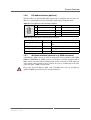
The DC1’s internal power supply supports SMBus slave device functionality. The 7bit SMBus address of the power supply unit is 0x09. Its microcontroller behaves
according to the SMBus Specification Version 2.0. The supported SMBus
commands and their functions are explained in the following chapters. The
commands are listed by their unique name. The "Data Range" column lists the valid
range of the data byte for the specific command code. The "Type" column specifies
the data direction for the specific command. 'r' specifies that the host can read the
data using the SMBus read-byte protocol. 'w' means the host can write data using
the SMBus write-byte protocol.
3.2.2
Wake On Time
The DC1 can be switched on/off by a programmable timer. The timer is included in
the internal power supply unit’s microcontroller and is programmable by the CPU
via SMBus commands (see Table 10, SMBus commands for wake on time function,
on page 29).
The behavior after power up by wake on time is identical to the behavior after power
up by key input. After the first wake on time event, the wake on time feature is
disabled.
Note: For the timer functionality it is necessary that the DC/DC converter and the
microcontroller are active, i.e. the power supply unit is connected to the DC/
DC converter, which is supplied with power. The DC1 will consume approx.
800 mW in this state.
Table 10. SMBus commands for wake on time function
Command
Code
Name
Data
Range
Type
Description
XC02C_WOT_L
0x00
0x00..
0xFF
r/w
Wake on time low byte
XC02C_WOT_H
0x01
0x00..
0xFF
r/w
Wake on time high byte
The wake on time delay can be configured via SMBus in a 16 bit counter to provide
the range according to the following table:
Table 11. SMBus commands XC02C_WOT_L / XC02C_WOT_H
Minimum
0 (OFF)
(default)
Maximum
Description
65,535 min
XC02C_WOT_L and XC02C_WOT_H build a
(45d 12h 15m) 16 bit value which represents the time in minutes
A user application that shall switch on the DC1 on a given date and time needs to
calculate the amount of minutes between shutdown and desired wake time.
MEN Mikro Elektronik GmbH
20DC01-00 E4 – 2011-01-26
29
Firmware Functions
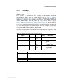
3.2.3
Watchdog
The internal power supply unit’s microcontroller is also used as a watchdog for
the DC1 system.
It is possible to enable/disable the watchdog by the SMBus command
XC02C_WDOG_STATE. After the XC02C_STATUS byte (see Table 16, SMBus
commands for shutdown delay, on page 32) signals a shutdown, the watchdog is
disabled by the firmware. The watchdog is triggered by cyclic SMBus commands
(XC02C_WDOG_TRIG) from the CPU. The time interval between trigger
commands is configurable via the SMBus command XC02C_WDOG_TOUT (see
Table 13, SMBus command XC02C_WDOG_TOUT, on page 30). The time interval
is set to its maximum value after DC1 power up and the watchdog is disabled. In
case of a missing trigger unit’s microcontroller resets the complete system. The
number of missing SMBus trigger command exceptions is incremented and can be
read via the SMBus command XC02C_WDOG_ERR.
After three exceptions, the microcontroller switches off the power output (Vout) and
switches off the display.
Table 12. SMBus commands for the watchdog function
Command
Code
Name
Data
Range
Type
Description
XC02C_WDOG_STATE
0x05
0x00,
0x01
r/w
Watchdog state
XC02C_WDOG_TRIG
0x06
0
w
Watchdog trigger
signal
XC02C_WDOG_TOUT
0x07
0x01..
0xFF
r/w
Watchdog timeout
in 100ms steps
XC02C_WDOG_ERR
0x08
0x00..
0x04
r
Number of missing
on watchdog
trigger signals
Table 13. SMBus command XC02C_WDOG_TOUT
Value
Watchdog Timeout
1
100 ms
2
200 ms
3
300 ms
...
255
MEN Mikro Elektronik GmbH
20DC01-00 E4 – 2011-01-26
25.5 s (default)
30
Firmware Functions
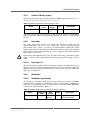
3.2.4
Status of Binary Inputs
The status of the binary inputs is also signaled via SMBus commands. See Table 14,
SMBus commands for binary inputs status, on page 31.
Table 14. SMBus commands for binary inputs status
Name
Command
Code
0x0E
XC02C_IN
Data
Range
Type
0x00..
0x1F
r
Description
State of binary inputs
The binary inputs represent the status of the key input and the 4 geographical
address inputs that allow a user application to find out e.g. where in a train a DC1 is
located.
3.2.5
Key Input
One of the binary inputs serves as an on/off input. When this signal is passive
(open) during power up of the input voltage, the system is not supplied with
power. When this signals goes active, the microcontroller switches the power
supply to provide the system with power. Regardless of the key input signal, the DC/
DC converter and the microcontroller are always supplied with power when the
input voltage is connected.
!
Note that key input functionality is only available when using a customized power
supply, as the key input signal from the included external power supply is always
active.
3.2.5.1
Key Input On
The microcontroller switches on the system power whenever the debounced state of
the key binary input switches from low to high state (On event). The microcontroller
debounces the key input in the following way: if the input is stable for 250ms, the
input state is interpreted.
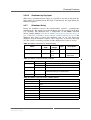
3.2.6
Shutdown
3.2.6.1
Shutdown by Software
At any time it is possible to shut down the power supply by software via SMBus
command XC02C_SWOFF. A shutdown by software is caused when an SMBus byte
write of 0x09 (command) and 0xA8 (magic value to avoid unintended shutdowns)
is done to the microcontroller’s address.
Table 15. SMBus command for shutdown by software function
Name
XC02C_SWOFF
MEN Mikro Elektronik GmbH
20DC01-00 E4 – 2011-01-26
Command
Code
0x09
Data
Range
0xA8
(magic)
Type
w
Description
Signal a software power
off from application
31
Firmware Functions
3.2.6.2
Shutdown by Key Input
When using a customized power supply, it is possible at any time to shut down the
power supply by switching off the key input. A shutdown by key input follows the
shutdown sequence.
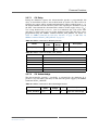
3.2.7
Shutdown Delay
During the shutdown sequence the microcontroller provides a programmable
shutdown delay. The default state of the shutdown delay after power up of the DC1
is 0 (disabled). The shutdown delay is configurable via the SMBus command
XC02C_DOWN_DELAY, see Table 16, SMBus commands for shutdown delay, on
page 32 and Table 18, SMBus command XC02C_DOWN_DELAY, on page 32. The
shutdown delay timer is started after shutdown event. At any time during the
shutdown delay the shutdown sequence can be stopped by an On event (key input
on). The system is in running state then and the shutdown delay timer is cleared.
Table 16. SMBus commands for shutdown delay
Command
Code
Name
Data
Range
Type
Description
XC02C_DOWN_DELAY 0x0B
0x00..
0x07
r/w
Shutdown delay
0x0D
0x00..
0x01
r
Signal PSU status
to application
XC02C_STATUS
Table 17. SMBus command XC02C_STATUS
Bit
0
1
2..7
Value
Description
0
Shutdown event not signaled
1
Signal shutdown event
0
Normal operation
1
Display in protect state
(over/under-voltage or temperature)
0
Reserved
Table 18. SMBus command XC02C_DOWN_DELAY
Value
0
0 min
1
1 min
2
2 min
3
4 min
4
8 min
5
16 min
6
32 min
7
64 min
MEN Mikro Elektronik GmbH
20DC01-00 E4 – 2011-01-26
Shutdown Delay
32
Firmware Functions
3.2.7.1
Off Delay
During the shutdown sequence the microcontroller provides a programmable Off
delay. As default this feature is not enabled (mode 0). In this case there will be no
Off delay, the supply will be switched off immediately. When enabled (mode 1…5),
the microcontroller starts the Off delay timer after signaling the shutdown event to
the CPU. After timeout the microcontroller switches off the supply voltage (Vout).
Vout is kept disabled for at least 1 s, even if an immediate On event occurs. This
guarantees a proper power on reset of the supplied system. The Off delay can be
programmed using the SMBus command XC02C_OFF_DELAY, for details see
Table 19, SMBus command for Off delay function, on page 33 and Table 20,
SMBus command XC02C_OFF_DELAY, on page 33.
Table 19. SMBus command for Off delay function
Command
Code
Name
XC02C_OFF_DELAY
0x0C
Data
Range
Type
0x00..
0x05
r/w
Description
Off delay
Table 20. SMBus command XC02C_OFF_DELAY
Mode value
Off Delay
0
Feature off (no Off delay, default)
1
1 min
2
2 min
3
4 min
4
8 min
5
16 min
3.2.7.2
Off Acknowledge
The microcontroller provides a possibility to acknowledge the shutdown. It is
possible at any time during Off delay to shut down the power supply by the SMBus
command XC02C_OFFACK.
Table 21. SMBus command for Off acknowledge function
Name
XC02C_OFFACK
MEN Mikro Elektronik GmbH
20DC01-00 E4 – 2011-01-26
Command
Code
0x0A
Data
Range
0
Type
w
Description
Signal Off acknowledge
33
Firmware Functions
3.2.8
Voltage Supervision
Input and output voltage are supervised by the microcontroller. The microcontroller
supervises the 12 V output voltage of the DC/DC converter by applying it through a
voltage divider to one ADC channel. The supervision ranges are set by the
commands XC02C_VOLT_HIGH and XC02C_VOLT_LOW. These values are
written with MDIS descriptors and are not to be changed during normal operation.
When the voltage is exceeding this range, the display is switched off for protection.
The output voltage is measured using the microcontroller internal ADC function.
The ADC value which represents the output voltage can be read via the SMBus
command XC02C_VOLT (see Table 22, SMBus command for voltage supervision
function, on page 34. With an ADC reference voltage of 3.00 volts the returned
value from this command is to be interpreted as
ADC
U mon = ------------- x3000mV
255
so that for example a returned value of 0xD5 corresponds to (0xD5/255)*3000mV =
2.506V. This value results from the voltage divider tap between a 10k and 2.7k
resistor (factor 0.212), so the real output voltage of the DC/DC converter is 2.506V/
0.212 = 11.8V. This would be a typical output under load.
Table 22. SMBus command for voltage supervision function
Name
Command
Code
Data
Range
Type
Description
XC02C_VOLT
0x14
0x00..
0xFF
r
DC/DC output (voltage
divider factor = 0,212)
XC02C_VOLT_LOW
0x22
0x00..
0xFF
r/w
Minimum allowed
display supply voltage
XC02C_VOLT_HIGH 0x21
0x00..
0xFF
r/w
Maximum allowed
display supply voltage
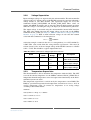
3.2.9
Temperature Supervision
The microcontroller is able to determine the temperature inside the DC1. The CPU
can read the current temperature via the SMBus command XC02C_TEMP. This is
independent from the temperature sensor and supervision functionality of the DC1’s
embedded system core itself.
The temperature supervision is carried out by the temperature sensor LM50. The
LM50 is a precision integrated-circuit temperature sensor that can sense a -40°C to
+125°C temperature range. It converts its temperature to an analog voltage
according to the formula below:
OUTPUT
Vout=(10mV/°C x Temp °C) + 500 mV
Vout=+1.750mV at +125°C
Vout=+750mV at +25°C
Vout=+100mV at -40°C
MEN Mikro Elektronik GmbH
20DC01-00 E4 – 2011-01-26
34
Firmware Functions
This voltage is also converted as explained in Chapter 3.2.8 Voltage Supervision, but
directly attached to the ADC channel since it is within the maximum ADC range of
3,000V. The Table 24. Temperature representation shows some values (which are
derived by (Vout/3000mV) x 0xFF).
Table 23. SMBus commands for temperature supervision
Name
Command
Code
Data
Range
Type
Description
XC02C_TEMP
0x12
0x00..
0xFF
r
Converted
temperature
XC02C_TEMP_LOW
0x18
0x00..
0xFF
r/w
Minimum
temperature value
XC02C_TEMP_HIGH
0x13
0x00..
0xFF
r/w
Maximum
temperature value
The default values are -10 to +60° and can be changed at MEN depending on the
display type.
!
When changing these settings manually do not exceed the panel’s maximum
operating temperature range of -30 to +70°C!
Table 24. Temperature representation
Value
Temperature
0x22
-10°C
0x2a
0°C
0x55
+50°C
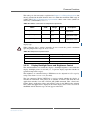
3.2.10
Display Backlight Power and Brightness Control
The microcontroller can control the display’s backlight brightness and switch the
display backlight power on and off (i.e., to prevent display operation outside its
specified temperature ranges).
The brightness is controlled using a PWM that can be adjusted in 0.5% steps by
using values from 0x00 to 0xC8 (0 to 200).
The last command, XC02C_INIT_DS, is used to control whether the display is
switched on immediate after power on or whether it remains dark until the user
application switches it on with a XC02C_SW_DISP command. This "silent boot"
feature allows application testing and entering values in the BIOS of the onboard
CPU. When the application is deployed, the initial display state can be set to off so
that BIOS and OS boot messages do not appear in the field.
MEN Mikro Elektronik GmbH
20DC01-00 E4 – 2011-01-26
35
Firmware Functions
Table 25. SMBus commands for display control
Command
Code
Name
Data
Range
Type
Description
XC02C_SET_BR
0x17
0x00..
0xC8
r/w
Set/get brightness level
XC02C_SW_DISP
0x20
0x00..
0x01
r/w
Switch display on (1)
or off (0)
XC02C_BR_SRC
0x19
0x00..
0x01
r/w
Brightness source:
SMB command = 0
Photo diode = 1
XC02C_INIT_DS
0x25
0x00..
0x01
r/w
Initial display state
at powerup:
on = 0
off = 1
3.2.11
Optional Autonomous Brightness Control with Photo
Diode
When the DC1 is equipped with a photo diode for light detection the firmware
allows to pass brightness control to it. The command XC02C_BR_SRC switches
control from brightness setting with the SMB command XC02C_SET_BR to
autonomous setting. In this case the value is updated every 5s so short coverages of
the diode don't affect brightness.
To keep the same version of the firmware for all DC1 variants, its also possible to
switch to autonomous brightness control when there no photo diode is present. In
that case the brightness will always stay the same.
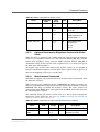
3.2.12
Miscellaneous Commands
The firmware supports some commands that are useful to retrieve information about
the build date and time.
With each call to the command XC02C_TIMESTAMP the firmware returns one
character of the build timestamp string that is stored in the microcontroller’s internal
EEPROM. This helps to identify the firmware version. The values returned are
concatenated in the MDIS driver and logged when the MDIS device that represents
the microcontroller is opened.
The command XC02C_ID returns a fixed value 0xC2 that is used to identify the
underlaying carrier board type. See Table 26, SMBus commands for PSU ID and
firmware revision number, on page 36.
Table 26. SMBus commands for PSU ID and firmware revision number
Name
XC02C_ID
Command
Code
0xFE
XC02C_TIMES 0x20
TAMP
MEN Mikro Elektronik GmbH
20DC01-00 E4 – 2011-01-26
Data
Range
Type
Description
0xC2
r
Fixed firmware ID
0x00..
0x01
r
Build date string, one
character at a time
36
Maintenance
4
Maintenance
4.1
Cleaning the Display
Please clean the display of the DC1 with a moist, soft cloth. Do not use abrasive
detergents in order to avoid damaging the laminated glass that protects the display.
4.2
!
Fuse Protection
The DC/DC converter inside the Power Supply Unit is protected by a fuse. This
fuse is not intended to be exchanged by the customer. Your warranty for the
Power Supply Unit will cease if you exchange the fuse on your own. Please send
your unit to MEN for repair if a fuse blows.
• Current rating:
- 1A for a 72 and 110V PSU
- 2.5A for a 48V PSU
- 5A for a 24V PSU (standard)
• Type: fast
• Size: 4.5 x 12.1
• MEN part number: 5675-0006 (1A), 5675-0010 (2.5A), 5675-0009 (5A)
MEN Mikro Elektronik GmbH
20DC01-00 E4 – 2011-01-26
37
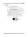
Appendix
5
Appendix
5.1
Literature and Web Resources
• DC1 data sheet with up-to-date information and documentation:
www.men.de/products/09DC01-.html
5.2
Finding out the Display Computer’s Article Number,
Revision and Serial Number
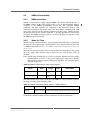
MEN user documentation may describe several different models and/or hardware
revisions of the DC1. You can find information on the article number, the board
revision and the serial number on two labels attached to the board.
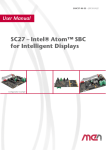
• Article number: Gives the unit’s family and model. This is also MEN’s ordering
number. To be complete it must have 9 characters.
• Revision number: Gives the hardware revision of the Display Computer.
• Serial number: Unique identification assigned during production.
If you need support, you should communicate these numbers to MEN.
Figure 6. Label giving the board’s article number, revision and serial number
Complete article number
Article No.:
09DC01-00
Serial No.:
012345
Rev. 00.00.00
Serial number
Revision number
MEN Mikro Elektronik GmbH
20DC01-00 E4 – 2011-01-26
38