1
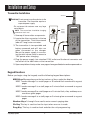
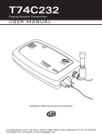
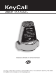
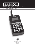
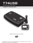
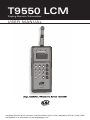
T9550 LCM
Paging System Transmitter
U S E R M A N UA L
T9550LCM
1
2
3
MSG
4
5
6
MSG
7
8
9
MSG
CLR
0
PROG
1
2
3
MSG
4
Long Range Systems
www.pager.net
U sa g e , I n sta l l at i o n , Warr an ty a n d S e rv i ce I n fo rm a ti o n
Long Range Systems UK Ltd | Link House | Leek Road | Milton | Stoke on Trent | Staffordshire | ST2 7AH | 01782 537000
www.lrspagers.co.uk | www.pagers.co | www.hospitalpagers.co.uk
Table Of Contents
Long Range Systems . . . . . . . . . . . . . . . . . . . . . . . . . . . . . . . . . . .
2
General Information . . . . . . . . . . . . . . . . . . . . . . . . . . . . . . . . . . .
2
Installation and Setup . . . . . . . . . . . . . . . . . . . . . . . . . . . . . . . . . .
3
Transmitter Installation . . . . . . . . . . . . . . . . . . . . . . . . . . . . . . . . . . . . .
3
Keypad Functions . . . . . . . . . . . . . . . . . . . . . . . . . . . . . . . . . . . . . . . . .
3
Basic Paging Operation Guide . . . . . . . . . . . . . . . . . . . . . . . . . . . .
4
Feature Setup Procedures . . . . . . . . . . . . . . . . . . . . . . . . . . . . . . .
5
Maintenance Functions . . . . . . . . . . . . . . . . . . . . . . . . . . . . . . . . .
6
Coaster/Pager Programming . . . . . . . . . . . . . . . . . . . . . . . . . . . . .
7
System Specifications . . . . . . . . . . . . . . . . . . . . . . . . . . . . . . . . . .
8
T9550 . . . . . . . . . . . . . . . . . . . . . . . . . . . . . . . . . . . . . . . . . . . . . . . . . . .
8
Rechargeable Pagers . . . . . . . . . . . . . . . . . . . . . . . . . . . . . . . . . . . . . .
8
Troubleshooting . . . . . . . . . . . . . . . . . . . . . . . . . . . . . . . . . . . . . .
9
Transmitter Display does not light when a key is pressed . . . . . . . .
9
Transmitter Display is okay, but the pager does not receive the page 9
Pager Charge Lights do not come on . . . . . . . . . . . . . . . . . . . . . . . . .
9
Service Questions and Answers . . . . . . . . . . . . . . . . . . . . . . . . . . 10
Warranty . . . . . . . . . . . . . . . . . . . . . . . . . . . . . . . . . . . . . . . . . . . . 11
Long Range Systems
1
T9550 LCM User Manual
Long Range Systems
Thank you for choosing Long Range Systems to provide your on-premise paging solution.
We provide cutting edge products and first-rate service to satisfy your needs for years to
come. Please familiarize yourself and your staff with the contents of this instruction in
order to properly operate and maintain your system. For help operating your system or
for any service problems, please call:
(800) 437-4996.
NOTE: Please keep this instruction in a safe place that is available to managers and key staff
General Information
This is an on-premise system used to increase efficiency by alerting people of immediate
needs. The pagers used with the system can vibrate, beep and display messages.
NOTICE: Operation is subject to the following:
• This device may not cause interference
• This device will accept any interference including interference that may cause
undesired operation of the unit.
Coaster Call
Guest Pagers
T9550LCM
1
1
4
2
3
MSG
1
1
Star Pager
Staff Pagers
2
3
4
4
5
6
MSG
7
8
9
MSG
CLR
0
PROG
800.437.4996
www.pager.net
2
3
Adverteaser
Guest Pager
MSG
4
1
ger
Star Pa
2
Long Range Systems
3
www.pager.net
4
.437.499
Long Range Systems
2
6
800
t
ager.ne
www.p
T9550 LCM User Manual
Installation and Setup
Transmitter Installation
Antenna
!
CAUTION:: Do not connect any other devices to the
transmitter. The transmitter requires a
separate power supply.
- Do not mount the antenna near any large
metal objects
T9550LCM
10 Vac
Power
Supply
NOTE: The transmitter should be charging
whenever not in use.
1. Unwrap all transmitter components.
CONDOR
(408)745-7141
CLASS 2 TRANSFORMER
INPUT: AC 12OV 60Hz 19w
OUTPUT: AC 9V 1800mA
P/N: A91A8
UL
2. Locate the silver connector in the top
of the transmitter. Twist the antenna
(about 3" long) onto connector.
3. The transmitter is transportable and
battery powered and will also run
when connected to the charger.
Mount the power supply in convenient location where there is access to
110V power when charging.
RoHS
LISTED
C
1
UL
MODEL: 48A -9- 1800
EIA 363 0635 S
MADE IN CHINA
2
3
MSG
1
4
5
6
MSG
7
8
9
MSG
CLR
0
PROG
2
3
MSG
4
Long Range Systems
Keypad
Transmitter
www.pager.net
4. Plug the power supply into standard 110V outlet and the barrel connector end
into either of the side holes on the transmitter.
5. Upon completion of setup make sure pagers have good batteries and are powered on.
Keypad Functions
Before you begin using the keypad, read the following keypad descriptions.
MSG Keys Message keys are the last column of keys under the display.
MSG 1 sends message 1 to a staff pager or 30 second flash command to a guest
pager.
MSG 2 sends message 2 to a staff pager or 5 minute flash command to a guest
pager.
MSG 3 sends message 3 to a staff pager or a 5-minute flash, vibe, and beep command to a guest pager.
MSG 4 sends message 4 to a staff pager or 5-minute glow command to a guest
pager.
Number Keys 1 through 0 are used to enter numeric paging data.
Clr Key This key is used to clear the input when an error is made
Prog Key. This key is used to check and alter the unit programming.
Long Range Systems
3
T9550 LCM User Manual
Basic Paging Operations
After all components have been charged the system is ready for use. The following describes the basic operation of the T9550.
Paging Staff Pagers (for units set for staff paging)
1. Enter the pager number
2. Press MSG button (MSG 1= pager indicator 1, MSG 2 = indicator 2, MSG 3 = indicator 3, or MSG 4 = indicator 4).
Paging Guest Coasters and Paddles (for units set for guest paging)
1. Enter the pager number
2. Press MSG button
• MSG 1 causes guest pager to flash/vibrate for 30-seconds
• MSG 2 causes guest pager to flash/vibrate for 5-minutes
• MSG 3 causes guest pager to flash/vibrate, and beep for 5-minutes
• MSG 4 causes guest pager to glow mode for 5-minutes
Page All Call
If all staff pagers need to be called simultaneously:
1. Press 0 - 0 - 0
2. Press a message key
Long Range Systems
4
T9550 LCM User Manual
FEATURE SETUP PROCEDURES
Set to Page Staff Pagers
For units that have been set to page guest pagers, enter 9 1 7 and press Prog key
Set to Page Guest Pagers
To set units to page guest coasters, enter 9 1 6 and press Prog key
Set Message Mode (Staff Pagers Only)
Set the Vibration as Station ID Regardless of Message Sent
To set the pagers to vibrate 1, 2, or 3 times dependent upon the calling station, enter 9 1 5
and press Prog key. The message lights will still be 1, 2, 3, or 4.
Set the Vibration Same as the Message Sent
To set the pagers to vibrate the same number of times as the message light displayed,
enter 9 1 4 and press Prog key. Note. Message 4 will have only 3 vibrations.
Long Range Systems
5
T9550 LCM User Manual
MAINTENANCE CHECKS
The performance of the T9550 may be checked and adjusted
Change System ID
This function is used where neighboring establishments use LRS equipment and may interfere with each other. Pagers and Transmitter MUST be on the same ID.
1. Press 9 0 X (X = ID 0, 1, 2, or 3).
2. Press Prog
Change Station ID
This function is used where more than one transmitter is used in one establishment. This
allows the staff pager to vibrate 1, 2 or 3 times (for station 1, 2, or 3).
1. Press 9 9 X (X =1, 2, or 3).
2. Press Prog
Checking the Battery
If operating on battery power, disconnect the transmitter from the adapter and press Prog.
The unit will show a number from 0 to 5
• If the unit shows 4 or above the charge is adequate for normal use
• If the unit shows 3, it is ok for short term use (1 or 2 hours)
• If the unit shows 2 or less (including blank) it must be recharged before use.
Reset to Default Paging Mode.
For units that may have had the battery completely discharged.
1. Connect the charger.
2. Press the reset button on the side of the transmitter and charge for 24 hours.
3. Enter 0 0 0 and press Prog key
Range Test
Range test is used to determine if there are areas of your establishment where the pagers
are not reliably paged. Usually moving a fixed transmitter a few feet solves this problem.
Mobile transmitters may sometimes be blocked by metal kitchen equipment. To perform
a range test:
1. Remove a pager(s) from the charger.
2. Press 9 1 2 Prog. The transmitter will show a 0 in the display that moves right to
left. All pagers will receive this message.
3. Move the pager(s) and Transmitter to different locations to determine if any dead
spots exist
Long Range Systems
6
T9550 LCM User Manual
COASTER/PAGER PROGRAMMING
The T95XXLCM will program the pagers and coasters.
1. Set the Mode for the type of pager/coaster being programmed
• 9 1 6 Prog for Guest
• 9 1 7 Prog for Star Pager (staff pagers).
2. Select the System ID (0, 1, 2, or 3).
3. Set Vibrator On/Off (Coaster Call Only)
• 9 2 0 Prog to set the Vibrator Motor On.
• 9 1 9 Prog to set the coaster to be silent when paged.
4. Remove the Coaster/Pager to be programmed from the charger.
5. When the pager/coaster stops flashing, press the pager number to program followed by Prog
6. After the pager/coaster responds by glowing and fading away, page the unit with
message 1 to be sure it programmed as desired and set aside.
7. Repeat steps 4 – 6 for the remaining units to be programmed.
Long Range Systems
7
T9550 LCM User Manual
System Specifications
Notice: Operation is subject to the following:
• This device may not cause interference.
• This device will accept any interference including interference that may cause
undesired operation of the unit.
T9550
Required Voltage: One-110V outlet for the transmitter keypad.
Operating Frequency: 467.750MHz
Radiated Power: <4900 micro-volts/meter
Operating Range: Dependent upon the paging environment.
Rechargeable Pager
Required voltage: (1) 110V outlet for 10VAC pager charger adapter.
Batteries: Nickel Metal Hydride (NiMH). Rechargeable. Lifetime of Batteries: Approximately 3-5 years
Battery life of pager: Approximately 48 hours (dependant on usage). Recharge time:
12 hours minimum from completely “dead”.
Long Range Systems
8
T9550 LCM User Manual
Troubleshooting
Transmitter Display does not light when a key is pressed
• Begin a battery charge procedure and check after 30-minutes.
• If the unit still is blank, check the charging power by substituting it with the
charging supply used for the pagers.
• If the supply is good, call LRS, if the supply is bad, either go to your local Radio
Shack and purchase Radio Shack # 273-1611 power supply as a replacement or
call LRS.
Transmitter Display is okay, but the pager does not receive the page.
• Perform a system reset.
• If the page still doesn’t work, be sure the Restaurant ID matches the pagers (see
page 6).
• Call LRS.
Pager Charge Lights do not come on:
1. When placed in charger, do all pagers have a single red charge light lit up?
• If no pagers have a charge light, skip to 2.
• If only some pagers have a charge light that is lit, skip to 3
• If all pagers have the charge light lit up, skip to 4 or 5.
2. You have probably blown the power supply.
3. Please remember that only 30 pagers can be on one 10V power supply. If you
have more than 30 pagers, call Long Range Systems.
4. You probably have a jumper wire that is not connected. Look on the side of your
chargers and verify all wires are connected properly. If they are connected, then
you may have dirty pagers contacts. Using a damp rag, clean the 2 metal contacts
on the back of each pager.
5. The cleaning crew may be disconnecting the pagers after hours. You may also
have the pagers on a circuit that automatically shuts off after hours. Please be
sure that all pagers are plugged in and charging when not in use.
Long Range Systems
9
T9550 LCM User Manual
Service Questions and Answers
Should your paging system ever fail or should you need additional paging equipment, call
Long Range Systems at (800) 437-4996.
Normal Business Hours
Monday – Friday 8:30 am to 5:00 pm Central Time.
Weekend or Evening Emergencies:
• Long Range Systems provides 24/7 live technical support.
• Please keep in mind that options are limited over the weekend.
Long Range Systems
10
T9550 LCM User Manual
Warranty
Long Range Systems, Inc. warrants this product against any defects that are due to faulty material or workmanship for
a two-year period after the original date of consumer purchase. This warranty does not include damage to the product
resulting from accident, misuse or improper electrical connection. If this product should become defective within the warranty period, we will repair or replace it with an equivalent product, free of charge. LRS will return your product via UPS
ground shipping. All warranty claims must be initiated through our customer service department.
Copyright © August 2008, Long Range Systems, Inc. All Rights Reserved
This manual contains proprietary information of Long Range Systems, Inc. (LRS) and is intended for use only by its employees or customers. None of the material contained herein may be copied, reproduced, republished, downloaded, displayed, posted, or transmitted in any form or by any means, including but not limited to, electronic, mechanical,
photocopying, recording, or otherwise without the prior written permission of LRS. Additional copies of this manual may
be obtained by contacting LRS.
Screen displays, keyboard layouts, hardware descriptions, or software are proprietary to LRS and are subject to copyright and other intellectual property rights of LRS and shall be treated in accordance with the previous paragraph.
All attempts have been made to make the information in this document complete and accurate. LRS is not responsible
for any direct or indirect damages or loss of business resulting from inaccuracies or omissions. Specifications and other
information contained within this document are subject to change without notice.
Long Range Systems, Inc. reserves the right to make changes without further notice to any products herein. LRS, Inc.
makes no warranty, representation or guarantee regarding the suitability of its products for any particular purpose, nor
does LRS, Inc. assume any liability arising out of the application or use of any product or circuit, and specifically disclaims
any and all liability, including without limitation consequential or incidental damages. “Typical” parameters that may be
provided in LRS, Inc. data sheets and/or specifications can and do vary in different applications and actual performance
may vary over time. All operating parameters, including “Typicals”, must be validated for each customer application by
customer’s technical experts. LRS, Inc. products are not designed, intended, or authorized for use as components in systems intended to support or sustain life, or for any other application in which the failure of the LRS, Inc. product could
create a situation where personal injury or death may occur. Should Buyer purchase or use LRS, Inc. products for any
such unintended or unauthorized application, Buyer shall indemnify and hold LRS, Inc. and its officers, employees, subsidiaries, affiliates, and distributors harmless against all claims, costs, damages, and expenses, and reasonable attorney
fees arising out of, directly or indirectly, any claim of personal injury or death associated with such unintended or unauthorized use, even if such claim alleges that LRS, Inc. was negligent regarding the design or manufacture of the part, device or system.
EU DECLARATION OF CONFORMITY
We, Long Range Systems hereby declare under our sole responsibility that the T9550 paging transmitters and on-site
pagers comply with the essential requirements in the European RE&TTE Directive 1999/5/EC of the European Parliament
of the Council of 9 March 1999 on radio equipment and telecommunication terminal equipment and the mutual recognition of their conformity. The following standards were utilized:
ETS 300 224: 1998
EN 301 489-2: 2002
EN61000-3-2: 1998
EN 61000-3-3: 1995
EN 60950: 1992 with A1, A2, & A
Long Range Systems
XU-0007 092509
11
T9550 LCM User Manual
Long Range Systems UK Ltd | Link House | Leek Road | Milton | Stoke on Trent | Staffordshire | ST2 7AH | 01782 537000
www.lrspagers.co.uk | www.pagers.co | www.hospitalpagers.co.uk