1
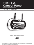
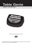
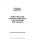
T12C/R1201
Seating Management System
U S E R M A N UA L
U sa g e , I n sta l l at i o n , Warr an ty a n d S e rv i ce I n fo rm a ti o n
Long Range Systems UK Ltd | Link House | Leek Road | Milton | Stoke on Trent | Staffordshire | ST2 7AH | 01782 537000
www.lrspagers.co.uk | www.pagers.co | www.hospitalpagers.co.uk
Table Of Contents
Long Range Systems . . . . . . . . . . . . . . . . . . . . . . . . . . . . . . . . . . . . . . . . . . . . .
2
General Information . . . . . . . . . . . . . . . . . . . . . . . . . . . . . . . . . . . . . . . . . . . . . .
2
T12C/R1201F Host Computer Table Management System Diagram . . . . . . . . . . . .
2
Installation and Setup . . . . . . . . . . . . . . . . . . . . . . . . . . . . . . . . . . . . . . . . . . . .
3
T12C Kyppad Functions . . . . . . . . . . . . . . . . . . . . . . . . . . . . . . . . . . . . . . . . . . .
4
Key Functions . . . . . . . . . . . . . . . . . . . . . . . . . . . . . . . . . . . . . . . . . . . . . . . . . . . . . . . .
4
Test and Resest Functions . . . . . . . . . . . . . . . . . . . . . . . . . . . . . . . . . . . . . . . . . . . . . .
4
T12C Specifications . . . . . . . . . . . . . . . . . . . . . . . . . . . . . . . . . . . . . . . . . . . . . .
5
Service Questions and Answers . . . . . . . . . . . . . . . . . . . . . . . . . . . . . . . . . . . . .
5
Warranty
6
......................................................
Long Range Systems
1
T12C User Manual
Long Range Systems
Thank you for choosing Long Range Systems to provide your on-premise paging solution. We provide cutting edge products and first-rate service to satisfy your needs for years to come. Please familiarize yourself
and your staff with the contents of this instruction in order to properly operate and maintain your system.
For help operating your system or for any service problems, please call:
(800) 437-4996
NOTE: Please keep this instruction in a safe place that is available to managers and key staff.
General Information
The Table Management Systems are on-premise systems used to increase efficiency by alerting staff of the
seating availability within the establishment. The base unit can be alerted from one or more hand held units
within the facility.
· The current status of each table is always available to the hostess station.
· Status can be changed from the floor or the hostess station.
· The R1201F base unit receiver is updated directly through a radio transmitter located in the T12C
hand held keypad.
NOTICE: Operation is subject to the following:
• This device may not cause interference
• This device will accept any interference including interference that may cause undesired operation of
the unit.
T12C/R1201F Host Computer Table Management System Diagram
888
1
4
7
SEAT
0
TRNSFR
CLR
CONDOR
(408)745-7141
CLASS 2 TRANSFORMER
INPUT: AC 12OV 60Hz 19w
OUTPUT: AC 9V 1800mA
P/N: A91A8
UL
3
OPEN
R1
20
FC
C ID
:M
74T
740
0
BUS
.pager.n
1F
RS
-23
2
et
R1201 F Base
Station Receiver
10V Power
Supply
Table Management Host
Computer System
Long Range Systems
UL
6
ENTER
T12C
Hand Held
Transmitter
C
9VAC
9
TEST
www
RoHS
LISTED
MODEL: 48A -9- 1800
EIA 363 0635 S
MADE IN CHINA
Rec
eive
Tran
sm
Pow
it
er
6
99 et
.4 r.n
37 ge
0.4 a
80 w.p
w
w
CLOSE
2
5
8
Table Status
Data
RS232
Interface Cable
2
T12C User Manual
Installation and Setup
Transmitter Installation
!
CAUTION: Do not mount the T12C transmitter or R1201F receiver antennas near any large metal objects.
NOTE: The T12C transmitter should be charging whenever not in use.
1. Unwrap all T12C transmitter and R1201F receiver components.
2. The T12C transmitter is portable and battery powered. It is charged in the same power charger
used for LRS paddle and star pagers.
3. Connect the antenna (about 3” long) onto the connector on the back of the receiver. It is best to
mount the antenna pointing straight up, perpendicular to the ground.
4. Mount the receiver convenient to a 110/220V power and near the host computer.
5. Plug the power supply into standard 110V/220V outlet and the barrel connector end into the side
hole on the R1201F receiver.
6. Connect the RS-232 cable from the R1201F receiver to the host computer.
7. Upon completion, perform the initialization on the host computer system (per manufacturer’s
specifications).
Long Range Systems
3
T12C User Manual
T12C Keypad Functions
Before you begin programming the transmitter, read the following keypad descriptions.
Functions Keys
The Function keys are described below.
Seat – clear the table from the Host Receiver list.
Open – list the table as ready on the Host Receiver.
Close – send the hold command to the Host Receiver.
Transfer – transfer guests from one table to another (Table# - Transfer - Table # - Enter).
Bus – send the Bus command to the Host receiver.
CLR – clear the input and restart
Test – check the % of battery life remaining (0 – 100%).
Enter – complete the Transfer function.
Number Keys
The number keys (1 – 0) are used to enter numeric data.
Test and Reset Functions
Version Check
Press 5 then the TEST key to check the version. The version as of this
publication is 1.12.
Battery Check
Press the TEST key to check the battery. The display shows a number to
indicate the battery charge (100 is fully charged and 1 is very weak).
Transmitter Reset
If the battery has been allowed to totally discharge, it may be necessary
to reset the transmitter for it to function properly. To reset the
transmitter:
1. Put the transmitter on charge.
2. After the transmitter is charged, enter 0-7-6 on the keypad.
3. Press the Test button.
Recharge
When the unit is on charge, the display flashes to show the charge level
• If the battery is fully discharged the unit will flash 0
• As the unit charges the number will increase in steps of 1%.
• At full charge the display will show 100 and the light on the charger will blink.
Range Test
The operating range of the unit can be checked by sending continuous open and close commands to the receiver while moving around the test area. To start the test, press 1-2-3 TEST. To end the test press Cancel.
Long Range Systems
4
T12C User Manual
T12C SPECIFICATIONS
The basic power and space requirements necessary for using the system are:
Required voltage: One 110/220V outlet for the R120F Receiver and Charger for T12C Transmitter .
Operating Frequency: 448.000MHz
Transmit Power: 10 mW
Operating Range: Approximately 1/4 mile (unobstructed)
SERVICE QUESTIONS AND ANSWERS
My System is malfunctioning - What do I do?
Should your seating system ever fail to function properly:
Call Long Range Systems at (800) 437-4996
Monday through Friday 8:30 am to 5:00 PM Central Time.
• After hours, please leave a message on the technical support line. LRS technicians are on call
and will return you call as soon as possible.
• Please keep in mind that options are limited over the weekend.
What about repairing my system after the warranty expires?
We suggest calling Long Range Systems before sending a non-warranty item in for repair.
** Out of warranty items will be repaired and sent back C.O.D.
Long Range Systems
5
T12C User Manual
Warranty
Long Range Systems, Inc. warrants this product against any defects that are due to faulty material or workmanship for
a two-year period after the original date of consumer purchase. This warranty does not include damage to the product
resulting from accident, misuse or improper electrical connection. If this product should become defective within the warranty period, we will repair or replace it with an equivalent product, free of charge. LRS will return your product via UPS
ground shipping. All warranty claims must be initiated through our customer service department.
Copyright © August 2008, Long Range Systems, Inc. All Rights Reserved
This manual contains proprietary information of Long Range Systems, Inc. (LRS) and is intended for use only by its employees or customers. None of the material contained herein may be copied, reproduced, republished, downloaded, displayed, posted, or transmitted in any form or by any means, including but not limited to, electronic, mechanical,
photocopying, recording, or otherwise without the prior written permission of LRS. Additional copies of this manual may
be obtained by contacting LRS.
Screen displays, keyboard layouts, hardware descriptions, or software are proprietary to LRS and are subject to copyright and other intellectual property rights of LRS and shall be treated in accordance with the previous paragraph.
All attempts have been made to make the information in this document complete and accurate. LRS is not responsible
for any direct or indirect damages or loss of business resulting from inaccuracies or omissions. Specifications and other
information contained within this document are subject to change without notice.
Long Range Systems, Inc. reserves the right to make changes without further notice to any products herein. LRS, Inc.
makes no warranty, representation or guarantee regarding the suitability of its products for any particular purpose, nor
does LRS, Inc. assume any liability arising out of the application or use of any product or circuit, and specifically disclaims
any and all liability, including without limitation consequential or incidental damages. “Typical” parameters that may be
provided in LRS, Inc. data sheets and/or specifications can and do vary in different applications and actual performance
may vary over time. All operating parameters, including “Typicals”, must be validated for each customer application by
customer’s technical experts. LRS, Inc. products are not designed, intended, or authorized for use as components in systems intended to support or sustain life, or for any other application in which the failure of the LRS, Inc. product could
create a situation where personal injury or death may occur. Should Buyer purchase or use LRS, Inc. products for any
such unintended or unauthorized application, Buyer shall indemnify and hold LRS, Inc. and its officers, employees, subsidiaries, affiliates, and distributors harmless against all claims, costs, damages, and expenses, and reasonable attorney
fees arising out of, directly or indirectly, any claim of personal injury or death associated with such unintended or unauthorized use, even if such claim alleges that LRS, Inc. was negligent regarding the design or manufacture of the part, device or system.
EU DECLARATION OF CONFORMITY
We, Long Range Systems hereby declare under our sole responsibility that the T12C paging transmitters and on-site
pagers comply with the essential requirements in the European RE&TTE Directive 1999/5/EC of the European Parliament
of the Council of 9 March 1999 on radio equipment and telecommunication terminal equipment and the mutual recognition of their conformity. The following standards were utilized:
ETS 300 224: 1998
EN 301 489-2: 2002
EN61000-3-2: 1998
EN 61000-3-3: 1995
EN 60950: 1992 with A1, A2, & A3
XU-0059 021610
Long Range Systems
6
T12C User Manual
Long Range Systems UK Ltd | Link House | Leek Road | Milton | Stoke on Trent | Staffordshire | ST2 7AH | 01782 537000
www.lrspagers.co.uk | www.pagers.co | www.hospitalpagers.co.uk