1
Part No. IB025911
Mar. 2013
USER’S MANUAL
EARTH CONTINUITY TESTER
TOS6200
TOS6210
Use of Operation Manual
There are four TOS6200/6210 Manuals listed as follows.
• Setup Guide (PDF)
This manual is intended for first-time users of this product. It provides an overview of the product and
notes on usage. It also explains how to set up the product for testing the DUT. Always read this manual
before using the product.
• Quick Reference
This manual explains Panel description and operation briefly.
• Safety Information
This document contains general safety precautions for this product. Keep them in mind and make sure to
observe them.
• User’s Manual (this manual)
This manual is intended for first-time users of this product. It provides an overview of the product and
notes on usage. It also explains how to configure the product, operate the product, remotely controlling
the product, perform maintenance on the product, and so on.
TOS6200/6210 Manuals are intended for users of the Earth Continuity Tester and their instructors. Explanations are given under the presumption that the reader has knowledge about the electrical aspects of electrical safety testing.
Every effort has been made to ensure the accuracy of this manual. However, if you have any questions, or
find any errors or omissions, please contact your Kikusui agent or distributor.
If you find any misplaced or missing pages in this manual, it will be replaced. If the manual gets lost or
soiled, a new copy can be provided for a fee. In either case, please contact your Kikusui agent or distributor, and provide the “Kikusui Part No.” given on the cover.
After you have finished reading manuals, store them so that you can use it for reference at any time.
Disposing of used Kikusui products in the EU
Under a law adopted by member nations of the European Union (EU), used electric and electronic products
carrying the symbol below must be disposed of separately from general household waste.
This includes the power cords and other accessories bundled with the products. When
disposing of a product subject to these regulations, please follow the guidance of your
local authority, or inquire with your Kikusui distributor/agent where you purchased the
product.
The symbol applies only to EU member nations.
Disposal outside the EU
When disposing of an electric or electronic product in a country that is not an EU member, please contact
your local authority and ask for the correct method of disposal.
The company names and product names that appear in this manual are the trademarks or registered trademarks of the respective manufacturers.
Reproduction and reprinting of this operation manual, whole or partially, without our permission is prohibited.
Both unit specifications and manual contents are subject to change without notice.
Copyright© 2005-2013 Kikusui Electronics Corporation
Safety Symbols
For the safe use and safe maintenance of this product, the following
symbols are used throughout this manual and on the product. Understand the meanings of the symbols and observe the instructions they
indicate (the choice of symbols used depends on the products).
or
DANGER
Indicates that a high voltage (over 1000 V) is used here. Touching
the part causes a possibly fatal electric shock. If physical contact
is required by your work, start work only after you make sure that
no voltage is output here.
Indicates an imminently hazardous situation which, if ignored, will
result in death or serious injury.
WARNING
Indicates a potentially hazardous situation which, if ignored,
could result in death or serious injury.
CAUTION
Indicates a potentially hazardous situation which, if ignored, may
result in damage to the product and other property.
Shows that the act indicated is prohibited.
Is placed before the sign “DANGER,” “WARNING,” or “CAUTION”
to emphasize these. When this symbol is marked on the product,
see the relevant sections in this manual.
Protective conductor terminal.
Chassis (frame) terminal.
On (supply)
Off (supply)
In position of a bi-stable push control
Out position of a bi-stable push control
TOS6200/6210
Safety Symbols
I
Safety Precautions
The following safety precautions must be observed to avoid fire hazard,
electrical shock, accidents, and other failures. Keep them in mind and
make sure that all of them are observed properly.
Use of the product in a method not specified in this manual may impair the protection functions of the product.
Users
• This product must be used only by qualified personnel who understand the contents of this operation manual.
• If it is handled by disqualified personnel, personal injury may result. Be sure to handle it under supervision of qualified personnel (those who have electrical knowledge.)
tion
Opera
l
Manua
Purposes of use
• Do not use the product for purposes other than those described in the operation
manual.
• This product is not designed or manufactured for household use or for general consumers.
Line
Voltage
Input power
• Always connect the product to an electrical outlet meeting the input rating of the
product.
• For applying power, use the AC power cord provided.
• The product is designed as equipment of Overvoltage Category II in the IEC Standards (energy-consuming equipment to be supplied from fixed installation).
Fuse
• The fuse can be replaced with a new one. When replacing a fuse, use the one
which has appropriate shape, ratings, and specifications.
Cover
• There are parts inside the product which may cause physical hazards. Do not
remove the external cover.
II
Safety Precautions
TOS6200/6210
L N G
Grounding
• The product is equipment of Safety Class I of the IEC Standards (equipment with
a protective conductor terminal). To avoid electrical shock, connect the protective
conductor terminal to electrical ground (safety ground).
Installation
• The product is designed to be safe when used indoors. Be sure to use it indoors
only.
• When installing products be sure to observe 2.2, “Precautions for Installation”
described in this manual.
Relocation
• Turn off the power switch and then disconnect all cables when relocating the
product.
• Be sure the operation manual be included when the product is relocated.
Operation
?
ck
Che
• Check that the AC input voltage setting and the fuse rating are satisfied and that
there is no abnormality on the surface of the power cord. Be sure to unplug the
power cord before checking.
• If any abnormality or failure is detected in the products, stop using it immediately.
Unplug the power cord or disconnect the power cord from the switchboard. Be
careful not to allow the product to be used before it is completely repaired.
• For output wiring, use connection cables with larger current capacity.
• Do not disassemble. If it must be modified, contact Kikusui distributor/agent.
Maintenance and checking
• To avoid electrical shock, be absolutely sure to unplug the power cord before performing maintenance or checking.
• Do not remove the cover when performing maintenance or checking.
• To maintain performance and safe operation of the product, it is recommended
that periodic maintenance, checking, cleaning, and calibration be performed.
Service
• Internal service is to be done by Kikusui service engineers. If the product must be
adjusted or repaired, contact Kikusui distributor/agent.
TOS6200/6210
Safety Precautions
III
Contents
Safety Symbols _____________________________________________ I
Safety Precautions _________________________________________ II
Chapter 1 General ________________________________________ 1-1
1.1
1.2
Overview of the Manual - - - - - - - - - - - - - - - - - - - - - - - - - - - - - - - - - - 1-2
Introduction and Features - - - - - - - - - - - - - - - - - - - - - - - - - - - - - - - - - 1-2
1.3
Options
- - - - - - - - - - - - - - - - - - - - - - - - - - - - - - - - - - - - - - - - - - - - - 1-5
Chapter 2 Installation and Preparation for Use __________________ 2-1
2.1
Unpacking Checks - - - - - - - - - - - - - - - - - - - - - - - - - - - - - - - - - - - - - - 2-2
2.2
2.3
2.4
Precautions for Installation - - - - - - - - - - - - - - - - - - - - - - - - - - - - - - - - 2-3
Precautions for Moving - - - - - - - - - - - - - - - - - - - - - - - - - - - - - - - - - - 2-5
Checking the Line Voltage - - - - - - - - - - - - - - - - - - - - - - - - - - - - - - - - 2-5
2.5
Connecting the AC Power Cord - - - - - - - - - - - - - - - - - - - - - - - - - - - - - 2-6
2.6
Grounding
2.7
Connecting the Test Leads - - - - - - - - - - - - - - - - - - - - - - - - - - - - - - - - 2-8
2.7.1 Supplied Test Lead TL11-TOS/TL12-TOS - - - - - - - - - - - - - - - - 2-8
2.7.2 Optional Test Probe LP01-TOS/LP02-TOS - - - - - - - - - - - - - - - 2-10
2.7.3 Other Leads - - - - - - - - - - - - - - - - - - - - - - - - - - - - - - - - - - - - 2-11
2.7.4 Measurements Using Four Terminals - - - - - - - - - - - - - - - - - - - 2-12
2.7.5 Measurements Using Two Terminals - - - - - - - - - - - - - - - - - - - 2-12
2.7.6 Connecting to the DUT - - - - - - - - - - - - - - - - - - - - - - - - - - - - 2-13
Preliminary Inspection - - - - - - - - - - - - - - - - - - - - - - - - - - - - - - - - - - 2-14
2.8
- - - - - - - - - - - - - - - - - - - - - - - - - - - - - - - - - - - - - - - - - - - 2-7
Chapter 3 Part Names and Functions _________________________ 3-1
3.1
Front Panel - - - - - - - - - - - - - - - - - - - - - - - - - - - - - - - - - - - - - - - - - - - 3-2
3.2
Rear Panel
- - - - - - - - - - - - - - - - - - - - - - - - - - - - - - - - - - - - - - - - - - - 3-6
Chapter 4 Basic Operation __________________________________ 4-1
IV
Contents
4.1
Turning on the power - - - - - - - - - - - - - - - - - - - - - - - - - - - - - - - - - - - - 4-2
4.2
Setting the Test Conditions - - - - - - - - - - - - - - - - - - - - - - - - - - - - - - - - 4-3
4.2.1 Test Current - - - - - - - - - - - - - - - - - - - - - - - - - - - - - - - - - - - - - 4-4
4.2.2 Test Frequency - - - - - - - - - - - - - - - - - - - - - - - - - - - - - - - - - - - 4-5
4.2.3 Upper Reference Value - - - - - - - - - - - - - - - - - - - - - - - - - - - - - - 4-5
4.2.4 Lower Reference Value - - - - - - - - - - - - - - - - - - - - - - - - - - - - - 4-8
4.2.5 Test Time - - - - - - - - - - - - - - - - - - - - - - - - - - - - - - - - - - - - - - 4-10
4.2.6 Offset Canceling Function - - - - - - - - - - - - - - - - - - - - - - - - - - 4-11
4.3
Starting and Ending Test - - - - - - - - - - - - - - - - - - - - - - - - - - - - - - - - - 4-13
4.3.1 Starting a Test - - - - - - - - - - - - - - - - - - - - - - - - - - - - - - - - - - - 4-13
4.3.2 Ending the Test - - - - - - - - - - - - - - - - - - - - - - - - - - - - - - - - - - 4-14
4.4
System Setup
4.5
Interface Setup
- - - - - - - - - - - - - - - - - - - - - - - - - - - - - - - - - - - - - - - - 4-16
- - - - - - - - - - - - - - - - - - - - - - - - - - - - - - - - - - - - - - - 4-20
TOS6200/6210
4.5.1
4.5.2
GPIB Address - - - - - - - - - - - - - - - - - - - - - - - - - - - - - - - - - - - 4-20
RS-232C Protocol - - - - - - - - - - - - - - - - - - - - - - - - - - - - - - - - 4-21
4.6
Panel Memory - - - - - - - - - - - - - - - - - - - - - - - - - - - - - - - - - - - - - - - 4-22
4.6.1 Storing in the Panel Memory - - - - - - - - - - - - - - - - - - - - - - - - - 4-22
4.6.2 Recalling the Panel Memory - - - - - - - - - - - - - - - - - - - - - - - - - 4-23
4.7
Program - - - - - - - - - - - - - - - - - - - - - - - - - - - - - - - - - - - - - - - - - - - 4.7.1 Recalling the Program - - - - - - - - - - - - - - - - - - - - - - - - - - - - 4.7.2 Creating or Editing the Program - - - - - - - - - - - - - - - - - - - - - - 4.7.3 Running the Program - - - - - - - - - - - - - - - - - - - - - - - - - - - - 4.7.4 Suspending the Program - - - - - - - - - - - - - - - - - - - - - - - - - - - 4.7.5 PASS/FAIL Judgment During Program Execution - - - - - - - - - 4.7.6 Ending the Program - - - - - - - - - - - - - - - - - - - - - - - - - - - - - - Key Lock - - - - - - - - - - - - - - - - - - - - - - - - - - - - - - - - - - - - - - - - - - Checking the Test Conditions - - - - - - - - - - - - - - - - - - - - - - - - - - - - 4.9.1 Setting Output out of the Operation Range - - - - - - - - - - - - - - 4.9.2 Upper Reference Value <= Lower Reference Value (UP <= LOW)
4-24
4-25
4-25
4-27
4-27
4-27
4-27
4-28
4-28
4-28
4-30
4.10 Protection Fuction - - - - - - - - - - - - - - - - - - - - - - - - - - - - - - - - - - - - 4.10.1 Time Limitation with Respect to Output (OVER HEAT) - - - - - 4.10.2 Overheating Protection (OVER HEAT) - - - - - - - - - - - - - - - - 4.10.3 Overload Protection (OVER LOAD) - - - - - - - - - - - - - - - - - - 4.10.4 Output Voltage Limitation (VOLT LIMIT) - - - - - - - - - - - - - - 4.10.5 Change in ENABLE Signal (SIGNAL I/O) - - - - - - - - - - - - - - -
4-31
4-31
4-32
4-32
4-33
4-33
4.8
4.9
4.11 Initialize
- - - - - - - - - - - - - - - - - - - - - - - - - - - - - - - - - - - - - - - - - - - 4-34
Chapter 5 REMOTE and SIGNAL I/O _________________________ 5-1
5.1
REMOTE Terminal - - - - - - - - - - - - - - - - - - - - - - - - - - - - - - - - - - - - - 5-2
5.2
SIGNAL I/O Connector - - - - - - - - - - - - - - - - - - - - - - - - - - - - - - - - - 5.2.1 SIGNAL I/O Connector Specifications - - - - - - - - - - - - - - - - - 5.2.2 Starting a Test - - - - - - - - - - - - - - - - - - - - - - - - - - - - - - - - - - - 5.2.3 Recalling a Panel Memory and Program - - - - - - - - - - - - - - - - - 5.2.4 Examples of Use - - - - - - - - - - - - - - - - - - - - - - - - - - - - - - - - -
5-3
5-4
5-6
5-7
5-8
Chapter 6 GPIB and RS-232C_______________________________ 6-1
TOS6200/6210
6.1
Interface - - - - - - - - - - - - - - - - - - - - - - - - - - - - - - - - - - - - - - - - - - - - 6-2
6.1.1 GPIB Interface - - - - - - - - - - - - - - - - - - - - - - - - - - - - - - - - - - - 6-2
6.1.2 RS-232C Interface - - - - - - - - - - - - - - - - - - - - - - - - - - - - - - - - - 6-2
6.2
Message and Terminator - - - - - - - - - - - - - - - - - - - - - - - - - - - - - - - - 6.2.1 Messages - - - - - - - - - - - - - - - - - - - - - - - - - - - - - - - - - - - - - - 6.2.2 Terminator - - - - - - - - - - - - - - - - - - - - - - - - - - - - - - - - - - - - 6.2.3 Special Symbols and Characters - - - - - - - - - - - - - - - - - - - - - - -
6.3
Device Messages - - - - - - - - - - - - - - - - - - - - - - - - - - - - - - - - - - - - - - - 6-7
6.3.1 Register-Related and General-Purpose Messages - - - - - - - - - - - - 6-7
6.3.2 System-Related Messages - - - - - - - - - - - - - - - - - - - - - - - - - - 6-13
6.3.3 Messages Relating to Test Conditions and Test Execution - - - - 6-18
6.3.4 Messages Relating to the Tester Status - - - - - - - - - - - - - - - - - - 6-26
Contents
6-4
6-4
6-6
6-6
V
6.3.5
6.3.6
Memory-Related Messages - - - - - - - - - - - - - - - - - - - - - - - - - - 6-29
Program-Related Messages - - - - - - - - - - - - - - - - - - - - - - - - - - 6-32
6.4
Registers
- - - - - - - - - - - - - - - - - - - - - - - - - - - - - - - - - - - - - - - - - - - 6-36
6.5
List of Device Messages - - - - - - - - - - - - - - - - - - - - - - - - - - - - - - - - - 6-40
6.6
Example Programs - - - - - - - - - - - - - - - - - - - - - - - - - - - - - - - - - - - - - 6-45
Chapter 7 Maintenance ____________________________________ 7-1
7.1
7.2
Cleaning - - - - - - - - - - - - - - - - - - - - - - - - - - - - - - - - - - - - - - - - - - - - 7-2
Inspection - - - - - - - - - - - - - - - - - - - - - - - - - - - - - - - - - - - - - - - - - - - - 7-2
7.3
Checking and Replacing the Fuse - - - - - - - - - - - - - - - - - - - - - - - - - - - - 7-3
7.4
7.5
Replacing the Cooling Fan and Backup Battery - - - - - - - - - - - - - - - - - - 7-4
Calibration - - - - - - - - - - - - - - - - - - - - - - - - - - - - - - - - - - - - - - - - - - - 7-4
7.6
In Case of Problems - - - - - - - - - - - - - - - - - - - - - - - - - - - - - - - - - - - - - 7-5
Chapter 8 Specifications ___________________________________ 8-1
8.1
Basic Performance - - - - - - - - - - - - - - - - - - - - - - - - - - - - - - - - - - - - - - 8-2
8.2
Interface and Other Functions
8.3
General Specifications
8.4
External Dimensions
- - - - - - - - - - - - - - - - - - - - - - - - - - - - - - 8-4
- - - - - - - - - - - - - - - - - - - - - - - - - - - - - - - - - - - 8-6
- - - - - - - - - - - - - - - - - - - - - - - - - - - - - - - - - - - - 8-8
Appendix _______________________________________________ A-1
A.1
A.2
Operational Principle - - - - - - - - - - - - - - - - - - - - - - - - - - - - - - - - - - - -A-1
ASCII Codes 20H to 7EH - - - - - - - - - - - - - - - - - - - - - - - - - - - - - - - - -A-2
A.3
Initial Settings of the Memory - - - - - - - - - - - - - - - - - - - - - - - - - - - - - -A-3
A.4
Summary of the Safety Standards for Earth Continuity Testing - - - - - - - -A-4
Index ___________________________________________________ I- 1
VI
Contents
TOS6200/6210
1
Chapter 1 General
Gives an overview of the tester and describes its features and various options.
TOS6200/6210
1-1
1.1
Overview of the Manual
This operation manual is for the TOS6200/6210 earth continuity tester.
■ Firmware version of products applied
This Operation Manual applies to products with version 1.0x firmware installed.
The ROM version number is displayed in the opening screen displayed immediately
after power is switched ON. You can also obtain the ROM version number with the
*IDN? message. For information on the *IDN? message, see 6.3.1, "RegisterRelated and General-Purpose Messages."
Before making product inquiries, please have ready the tester ROM version number
and serial number indicated on the rear panel of your tester.
TOS6200
EARTH CONTINUITY TESTER
Ver.
1.01
KIKUSUI ELECTRONICS CORP.
Fig.1-1
1.2
Opening screen for firmware version 1.01
(Example of TOS6200)
Introduction and Features
This tester is used to perform earth continuity tests required for class-I devices for
various safety standards, including the IEC, EN, UL, VDE, BS, JIS, and the Electrical Appliance and Material Control Law of Japan.
The tester must be used under the following conditions:
Test current value
TOS6200
TOS6210
3A to 30 A AC
6A to 60 A AC
Output terminal voltage
1-2
General
5.4 V or less
Resistance value
1.2 or less
0.6 or less
Maximum power
150 VA or less
220 VA or less
TOS6200/6210
1. Making test current constant
The test current for earth continuity tests has been made constant. This eliminates
the need to alter the test current, even if the resistance of the DUT (device under
test) changes.
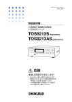
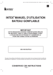
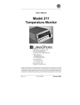
2. Safety output voltage
The constant current/constant voltage circuit provides fast response, preventing generation of excessive output voltage even when output is interrupted during testing.
The tester complies with the limitations on no-load output voltages (6 V or less,
12 V or less, and so on) required by many safety standards.
CH1: Voltage waveform
CH1: Voltage waveform
CH2: Current
waveform
Short circuit
CH1: 5 V/div
CH2: 50 A/div
TOS6210
CH2:Current waveform Open
10 ms/div
CH1: 5 V/div
CH2: 50 A/div
TOS6210
10 ms/div
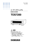
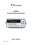
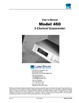
3. Reduced cycle time
A test current is a constant current value set within approximately 100 ms.
Earth continuity tests can be conducted even at 1-second intervals. This enables the
instrument to perform tests in production lines that require reduced cycle times.
CH1: Current waveform
TOS6210
CH1: 50 A/div
20 ms/div
4. Compact and lightweight
A new high-efficiency power supply (achieving a power conversion efficiency of
65%) and large output (TOS6200: 150 VA, TOS6210: 220 VA) makes possible a
tester that is remarkably compact and lightweight, about half the size and weight of
our conventional testers.
5. Excellent measurement accuracy
The tester is equipped with an ohmmeter of +/-(2% of reading + 0.003 ) that calculates resistance values based on measured current and voltage.
6. Offset canceling function
The tester has an offset canceling function that cancels values for contact resistance
at alligator clip connections, the contact resistance of measuring leads in measurements using two terminals, and other resistance components.
TOS6200/6210
General
1-3
7. Contact check function
The tester is provided with a contact check function that verifies the connection of
the DUT (by current detection) before initiating testing.
8. Voltage judgment function (TOS6210 only)
This function allows either a resistance value or a voltage drop value (voltage
between the SAMPLING terminals) to be selected as the reference value for judgment criteria.
It also allows voltage drop value-based testing to be conducted, which is required by
safety standards such as UL 60950-1 and IEC 60950-1.
9. Simple operations
Tester functions are fast and easily controlled, with an intuitive control method that's
easy to pick up, even for first-time users.
For example, test conditions are set simply by selecting an item displayed on the
LCD with the cursor keys and turning the rotary knob to set/select a value.
Any items you wish to set up can be assigned to the function keys.
10. Stores up to 100 types of test conditions
The tester allows you to store and name up to 100 test conditions involving parameters such as test current, determined resistance value, and test time. For example,
you can store test conditions for a specific safety standard under the name of the
standard, or store test conditions under the name of the destination of the DUT.
When test conditions need to be modified due to changes in the destination of the
product or revised safety standards, you can recall a set of test conditions simply by
entering a memory number, making necessary modifications to the pre-existing
standard.
Assigning specific names allows test conditions to called up by name. This function
is available through both the front panel and the remote control.
11. Programming of test conditions
A combination of stored test conditions allows automatic execution of tests consisting of several programs of up to 100 steps each.
Although the total number of steps is limited to 500, 100 types of programs can be
stored and recalled from the front panel or the remote control.
12. GPIB and RS-232C interfaces
The tester is provided with standard GPIB and RS-232C interfaces. It is therefore
not necessary to buy additional GPIB and RS-232C boards.
An interface cable and PC or sequencer allows remote control of test conditions
such as test current, determined resistance value, and testing time. Measured values
and test results can also be read back.
13. Supplied test leads
The tester comes with alligator clip test leads, letting you start testing immediately.
14. Memo function
The tester has a memo function that can store up to 20 characters per line on 3 lines,
which can be used to store serial numbers, calibration dates, and/or comments.
1-4
General
TOS6200/6210
1.3
Options
The following options are available for the tester.
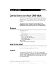
■ RC01-TOS/RC02-TOS Remote Control Box
When connected to the REMOTE terminal on the front panel, remote control boxes
are used to control tester start/stop functions.
The RC01-TOS has one START switch, while the RC02-TOS has two START
switches. For the RC02-TOS, a test starts only when both switches are pressed
simultaneously.
Functions
OPERATE switch
Test switches are enabled only when this switch is set to the ON position.
When it is set to the OFF position, a test in progress will be stopped.
START switch
With the OPERATE switch set to ON and the tester in ready status, press this
switch to start testing.
STOP switch
Used to shut off output voltage or cancel a FAIL status; has the same function
as the STOP switch located on the tester.
RC01-TOS:
200mm(W) x 70mm(H) x 39mm(D)
TOS6200/6210
RC02-TOS:
330mm(W) x 70mm(H) x 39mm(D)
General
1-5
■ LP01-TOS/LP02-TOS Test Probe
This probe lets you use the switches located on the probe to control tester starting
test/stopping test operations. Connect it to the OUTPUT and REMOTE terminals
on the tester's front panel.
Maximum rating: LP01-TOS
30 A
LP02-TOS
60 A
Cable length:
2m
Accessory:
LOW Test Lead (LP01-TOS/LP02-TOS) 2 m
LP01-TOS:
28 mm(W) x 45.5 mm(H) x 226 mm(D)
LP02-TOS:
28 mm(W) x 45.5 mm(H) x 226 mm(D)
LOW Test Lead
1-6
General
TOS6200/6210
2
Chapter 2 Installation and
Preparation for Use
Describes the steps from unpacking to installation to preparation required before
switching on POWER.
TOS6200/6210
2-1
2.1
Unpacking Checks
Upon receiving the product, make sure the package contains the necessary accessories, and that the product has not been damaged during transportation.
If any damage or imperfection is found, contact Kikusui distributor/agent.
The power cord that is provided varies depending on
the destination for the product at the factory-shipment.
or
AC power cord, 1
PLUG: NEMA5-15
or
PLUG: CEE7/7
[85-10-0840]
PLUG: GB1002
[85-10-0790]
[85-AA-0003]
Installed between
the OUTPUT and
SAMPLING terminals
Inserted in the
AC LINE connector
Spare fuse, 1
Test leads, 1 set
6.3 A 250 V
TOS6200: TL11-TOS 1.5 m
TOS6210: TL12-TOS 1.5 m
[99-02-0019]
Setup Guide (1 pc.)
[Z1-005-760]
Quick Reference
Japanese: 1 pc. [Z1-005-750]
English: 1 pc. [Z1-005-752]
Short-circuit bars, 2
[E3-300-032]
Safety Information
(1 pc.)
[Z1-005-040]
CD-ROM (1 pc.) ᳕SA-6061᳗
Fig.2-1
List of Accessories
SIGNAL I/O, GPIB interface, and RS-232C interface cables are not supplied with
the product and must be purchased separately.
For information on connecting those cables, see 5.2, “SIGNAL I/O Connector” and
Chapter 6, “GPIB and RS-232C.”
NOTE
2-2
• Packing materials may be used for later transport of the product, so it is recommended that they be retained.
Installation and Preparation for Use
TOS6200/6210
2.2
Precautions for Installation
The product should be installed indoors, observing the following precautions.
Precautions for installation location
■ Do not use the product in a flammable atmosphere.
To prevent explosion or fire, do not use the product near alcohol, thinner, or other
combustible materials, or in an atmosphere containing such vapors.
■ Avoid locations where the product is exposed to high temperatures or direct sunlight.
Do not locate the product near a heater or in areas subject to drastic temperature
changes.
Operating temperature range: 5C to 35C (41 F to 95 F)
Storage temperature range: -20C to +70C (-4 F to +158 F)
■ Avoid humid environments.
Do not locate the product in a high-humidity environment - near a boiler, humidifier,
or water supply.
Operating humidity range: 20% to 80% R.H (no dew condensation is allowed)
Storage humidity range: 90% R.H or less (no dew condensation is allowed)
Condensation may occur even within the operating humidity range. In that case, do
not start using the product until condensation dries up completely.
■ Do not place the product in a corrosive atmosphere.
Do not locate the product in a corrosive atmosphere or one containing sulfuric acid
mist or the like. This may cause corrosion of various conductors and imperfect contact with connectors, leading to malfunction and failure, or in the worst case, a fire.
■ Do not locate the product in a dusty environment.
Dirt and dust in the product may cause electrical shock or fire.
■ Do not use the product where ventilation is poor.
The product employs a forced-air cooling system. Provide sufficient space around
the product so that air is able to flow through the intake ports on the sides and the
exhaust port at the rear.
■ Do not place any object on the product.
Particularly a heavy one, as doing so could result in a malfunction.
■ Do not place the product on a tilted surface or in a location
subject to vibrations.
The product may fall or tip over causing damages and injuries.
TOS6200/6210
Installation and Preparation for Use
2-3
■ Do not use the product in locations affected by strong magnetic or electric fields.
Operation in a location subject to magnetic or electric fields may cause the product
to malfunction, resulting in electrical shock or fire.
■ Secure adequate space around the power plug.
Do not insert the power plug to an outlet where accessibility to the plug is poor.
And, do not place objects near the outlet that would result in poor accessibility to
the plug.
■ Use the product in an industrial environment.
This product may cause interference if used in residential areas. Such use must be
avoided unless the user takes special measures to reduce electromagnetic emissions
to prevent interference to the reception of radio and television broadcasts
Use of the feet
Used to raise the front panel of the meter to get a better view of the LCD screen or
improve the operability of the keys.
Pull the provided feet forward onto the floor until you hear them click.
Fig. 2-2
How to use the feet
CAUTION • Do not use the rubber strips on the sides as feet. Use of the product in an
upright position with a rubber strip at the bottom may cause the product to
fall down, resulting in damage to the tester or injury to the user.
2-4
Installation and Preparation for Use
TOS6200/6210
2.3
Precautions for Moving
When moving or transporting the product to an installation site, observe the following precautions.
■ Turn the POWER switch off.
Moving the product with the power on may result in electrical shock or damage.
■ Remove all wirings connected.
Moving the product with cables connected may break the cables or cause the product to fall, resulting in injury.
■ For transportation, use the special packing material for the
product.
Transport the product in its original package to prevent vibration and falls, which
may damage the product.
2.4
Checking the Line Voltage
The product is designed as equipment of Overvoltage Category II in the IEC Standards (energy-consuming equipment to be supplied from fixed installation).
Before connecting the AC power cord, check the tester’s line voltage.
Its input rating is indicated on the rear panel.
CAUTION • Using the tester outside the permitted range will result in erratic function or
failure. Operate the product with the supply voltage within the voltage
range required.
TOS6200
LINE VOLTAGE
RANGE
●
85-132V
170-250V
FUSE (250V)
FREQUENCY
RANGE
UL198G
IEC60127
47-63Hz
6.3A SLOW
6.3A (T)
VA
MAX
450
330
The ● symbol indicates the allowable line voltage range. If this symbol is placed by
both line voltage ranges, the tester may be used at either line voltage.
The line voltage range for the table above is as follows:
Allowable line voltage range: 85 V to 132 V AC
Allowable frequency range: 47 to 63 Hz
TOS6210
TOS6200/6210
FUSE (250V)
LINE VOLTAGE
RANGE
FREQUENCY
RANGE
UL198G
IEC60127
VA
MAX
85-250V
47-63Hz
6.3A SLOW
6.3A (T)
420
Installation and Preparation for Use
2-5
2.5
Connecting the AC Power Cord
The power cord that is provided varies depending on the destination for the product
at the factory-shipment.
WARNING • The AC power cord for 100 V system shown in Fig. 2-3 has a rated voltage
of 125 VAC. If this AC power cord is used at the line voltage of a 200 V system, replace the AC power cord with that satisfying that line voltage.
An appropriate AC power cord must be selected by qualified personnel. If
it is difficult to obtain the AC power cord, consult your Kikusui distributor/
agent.
NOTE
• The AC power cord incorporates a disconnecting device capable of isolating the
product from the AC power line should such become necessary. Connect it to an
easily accessible electrical outlet.
• Do not use the AC power cord provided with the product as a AC power cord for
other instruments.
[85-AA-0003]
PLUG:NEMA5-15
[85-10-0840]
PLUG:CEE7/7
Power cord for 100 V system
Rated voltage: 125 VAC
Rated current: 10 A
Power cord for 200 V system
Rated voltage: 250 VAC
Rated current: 10 A
[85-10-0790]
PLUG:GB1002
Fig. 2-3
AC power cord
Procedure
1.
Check that the power supply falls within the input line voltage range
indicated on the tester.
2.
Check that the POWER switch of the tester is set to OFF.
3.
Connect the AC power cord to the AC LINE connector on the rear panel
of the tester.
Use the provided power code or power code that is selected by qualified personnel.
4.
Connect the other end of the AC power cord to an electrical outlet.
For details on the rear panel, see 3.2, “Rear Panel.”
2-6
Installation and Preparation for Use
TOS6200/6210
2.6
Grounding
WARNING • The product is equipment of Safety Class I of the IEC Standards (equip-
ment with a protective conductor terminal). Be sure to connect the protective conductor terminal of the product to an electrical ground (safety
ground) to prevent electric shock.
CAUTION • If no grounding is provided, a malfunction may result from external noise
and/or the product may generate a large amount of noise.
There are two ways to ground the tester, as given below.
● Connect the AC power cord to a
three-contact grounded electrical
outlet.
Grounded three-contact
electrical outlet
● Connect the protective conductor terminal on the rear panel of the tester directly
to ground.
Selection, preparation, and installation of grounding leads must be performed by qualified personnel.
To ground
directly
TOS6200/6210
Installation and Preparation for Use
2-7
2.7
Connecting the Test Leads
WARNING • This product carries a maximum current flow of 30 A or 62A. Always check
to make sure that no connections are loose. Loose connection will result in
overheating of the OUTPUT terminals or the DUT (Device Under Test),
which may then result in burns or injury.
• Never connect the voltage measurement cable (thin wire) of the supplied
test leads or optional test probe to the OUTPUT terminals. The nominal
sectional area of this wire is inadequate for such currents, and burning
may result.
CAUTION • This product carries a large current and consequently generates a strong
magnetic field. Make sure that no articles that may be affected by magnetic fields are located near the test leads or current output lines.
For example, images on a CRT positioned close by may be significantly
distorted.
2.7.1
Supplied Test Lead TL11-TOS/TL12-TOS
1.
Remove the short-circuit bars connecting the OUTPUT and SAMPLING
terminals.
TOS6200
TOS6210
Take care not to get your finger
caught between the output
terminals when turning the knobs.
2-8
Installation and Preparation for Use
TOS6200/6210
2.
Connect the current output line on the crimp terminal side of the test
lead (black or white) to the LOW side of the OUTPUT terminals; connect the voltage measurement line on the banana plug side to the LOW
side of the SAMPLING terminals. Check that the connections are
secure.
3.
Connect the current output line on the crimp terminal side of the test
lead (red) to the HIGH side of the OUTPUT terminals; connect the voltage measurement line on the banana plug side to the HIGH side of the
SAMPLING terminals. Check that the connections are secure.
WARNING • Improper terminal connections can result in inaccurate measurements and
burns or injury resulting from heat generated by contact resistance at the
terminals.
Connecting example of TOS6200
4.
Connect the alligator clip of the test lead (black or white) to the protective conductor terminal of the DUT.
5.
Connect the alligator clip of the test lead (red) to a test point of the DUT.
For details, see 2.7.6, “Connecting to the DUT.”
CAUTION • Make sure that the alligator clip connections are secure.
Improper connections may result in clip disconnection, causing sparking
and potentially damaging the DUT.
TOS6200/6210
Installation and Preparation for Use
2-9
2.7.2
Optional Test Probe LP01-TOS/LP02-TOS
WARNING • Never connect the voltage measurement cable (thin wire) of the optional
LP01/LP02-TOS test probe to the OUTPUT terminals. Its nominal sectional area is inadequate for such currents, and burning may occur.
• The rated current of the LP01-TOS and LP02-TOS test probes are up to
30 A and 60 A, respectively. Do not attempt to pass a current exceeding
the rated current.
• Improper terminal connections can result in inaccurate measurements and
burns or injury resulting from heat generated by contact resistance at the
terminals.
1.
Turn off the POWER switch of the Tester.
2.
Remove the short-circuit bars connecting the OUTPUT and SAMPLING
terminals.
3.
Connect the LOW test lead to the LOW terminal of the Tester.
4.
Connect the each cable of the test probe to the HIGH and REMOTE terminal of the Tester.
Figure shows connections of the
TOS6210 with the LP02-TOS.
TOS6210
To SAMPLING
LOW terminal
To OUTPUT
LOW terminal
To the REMOTE terminal
To SAMPLING
HIGH terminal
To OUTPUT
HIGH terminal
2-10
Installation and Preparation for Use
TOS6200/6210
2.7.3
Other Leads
WARNING • If you use a lead wire other than those supplied with the product, select
wires of the nominal sectional areas meeting the test current.
CAUTION • To avoid generating excessive heat at the connections, use crimp termi-
nals appropriate for the sectional area of the current output line.
Select wires on the basis of the following criteria.
Test Current (I)
Required Nominal Sectional Areas of Wire
I30 A
5.5 mm2 or more
30 < I60 A
14 mm2 or more
Resistance values with respect to the nominal sectional areas of wires are as follows:
Use lead wires within a total lead length of 10 m or less.
TOS6200/6210
Nominal Sectional Areas of Wire
Resistance Value per Meter
5.5 mm2
3.5 m
14 mm2
1.5 m
Installation and Preparation for Use
2-11
2.7.4
Measurements Using Four Terminals
Four-terminal measurements allow the tester to measure the resistance of the DUT,
excluding the minute resistance of the leads, contact resistance of the OUTPUT terminals, and other non-essential characteristics.
OUTPUT
LOW
HIGH
r1
R1
r2
LOW
r5
r6
R2
Remove the short-circuit bars connecting the OUTPUT and SAMPLING terminals and connect the
leads as shown in Fig. 2-4.
Sampling the voltage between A and B allows the
tester to measure the resistance between A and B
without interference from the effects of contact resistance r1 to r8 and resistance components R1 to R4 of
the leads.
HIGH
SAMPLING
R3
R4
r7
r8
r3 A
r1 to r8: Contact resistance
R1 to R4: Resistance of the leads
r4
B
DUT: Device Under Test
Fig. 2-4
2.7.5
Four-Terminal Connection
Measurements Using Two Terminals
Perform two-terminal measurements if four-terminal measurements can't be made.
Note that measurements using two terminals will include the resistance components
of the leads and the contact resistance of the OUTPUT terminals.
OUTPUT
LOW
HIGH
r1
r2
R1
R2
LOW
Install the short-circuit bars between the OUTPUT
and SAMPLING terminals and connect the leads as
shown in Fig. 2-5. The tester measures the total
resistance value of contact resistance r1 to r4, resistance components R1 and R2 of the leads, and the
resistance between A and B.
HIGH
SAMPLING
r3 A
B
r4
r1 to r4: Contact resistance
R1 to R2: Resistance of the leads
DUT: Device Under Test
Fig. 2-5
Two-Terminal Connection
Two-terminal measurements can be performed with the resistance components (R1,
R2) of the leads and the contact resistances (r1 to r4) of the OUTPUT terminals subtracted beforehand. For more information, see 4.2.6, “Offset Canceling Function.”
2-12
Installation and Preparation for Use
TOS6200/6210
2.7.6
Connecting to the DUT
Connect to the DUT when the tester status is either of the following:
• Ready (“READY” displayed on the LCD)
• Waiting during a contact check (TEST LED blinking)
WARNING • To avoid burns, do not inadvertently touch the testing point or the end of
the test probe or lead during the test or immediately after test, since they
are at high temperature.
■ Testing from the protective conductor terminal of the AC
power inlet
Connect one of the test leads to the protective conductor terminal of the AC power
inlet of the DUT; connect the other test lead to a test point.
■ Testing from the protective conductor terminal on the enclosure
Connect one of the test leads to the protective conductor terminal of the DUT; connect the other test lead to a test point.
TOS6200/6210
Installation and Preparation for Use
2-13
■ Testing from the ground contact of the AC power cord
Connect one of the test leads to the ground contact of the AC power cord of the
DUT; connect the other test lead to a test point.
NOTE
2.8
• Some safety standards specify excluding the resistance value of the AC power
cord protective ground wire from testing. Check the appropriate safety standard
to determine if this is the case.
Preliminary Inspection
Always inspect the following four points before testing.
• Check that the test lead covers are free of cracks or tears.
• Check that there are no breaks in the test leads.
• Short-circuit the ends of the test leads and test at a specified current to check for
abnormalities.
• Perform the test with the OUTPUT terminals opened. This test must result in a
FAIL judgement.
2-14
Installation and Preparation for Use
TOS6200/6210
3
Chapter 3 Part Names and
Functions
Gives the names and functions of switches, keys, indications, connectors, and other
parts on the front and rear panels.
TOS6200/6210
3-1
3.1
Front Panel
[4] OUTPUT
[5] SAMPLING
Setup keys (see Fig. 3-2)
[3] START
[6] LCD
EARTH CONTINUITY TESTER
OUTPUT
TOS6210
TEST
PASS
FAIL
PROTECTION
HIGH
LOW
FUNCTION
MAX
60A
[2] STOP
GPIB
MAIN
SYSTEM
LOCAL
OFFSET
I/F
KEY LOCK
RMT
ON 10min / OFF 10min
REMOTE
AUTO
MEMORY
RECALL
ENTRY
[1] POWER
ENTER
MAX
20V
EDIT
STORE
CURSOR
MAX
10V
HIGH
LOW
SAMPLING
F1
F2
F3
F4
F5
F1
F2
F3
F4
F5
[8] REMOTE
SHIFT
POWER
[9] Function keys
[7] Feet
Fig.3-1
[1]
Front Panel (example of TOS6210)
POWER
Turns the tester power ON/OFF. When power is turned ON ( | ), the tester starts
under the test conditions set when power was turned OFF ( O ).
Turning the power ON with the SHIFT key held down initializes the tester to factory-set settings. For initialization, see 4.11, “Initialize,” and for turning the power
ON, see 4.1, “Turning on the Power.”
NOTE
• Initializing clears the contents of all panel memories and programs stored. Check
all data in memories and programs before initializing.
[2]
STOP
This switch is used to stop a test.
Press this switch to cancel a PASS, FAIL, or PROTECTION status.
Pressing this switch places the tester in ready status.
[3]
START
This switch is used to start a test.
Press this switch when "READY" is displayed on the LCD to begin testing.
During testing, the TEST LED indicator lights and a "TEST" indication appears on
the LCD.
3-2
Part Names and Functions
TOS6200/6210
[4]
OUTPUT
These current output terminals are used to connect current output wires for testing.
CAUTION • The maximum input voltage between the OUTPUT terminals and chassis
is 20 V AC/DC or less. Do not apply an external voltage exceeding this
limit.
[5]
SAMPLING
These voltage input terminals are used to connect voltage measuring wires for fourterminal measurements.
CAUTION • The maximum input voltage between the SAMPLING terminals is 10 V AC/
DC or less. Do not apply external voltage exceeding this limit.
[6]
LCD
Displays information, including the range of set values and measured values.
[7]
Feet
Used to raise the front panel of the tester to get a better view of the LCD screen or
improve the operability of the keys.
For usage of the feet, see 2.2, “Precautions for Installation.”
[8]
REMOTE
This terminal is used to connect an optional remote control box or dedicated test
probe.
[9]
Function keys
Provide functions corresponding to the F1 to F5 menus displayed on the LCD.
TOS6200/6210
Part Names and Functions
3-3
[16] Indicators
S6210
TEST
[10] SYSTEM / I/F
PASS
FAIL
PROTECTION
FUNCTION
GPIB
MAIN
SYSTEM
LOCAL
OFFSET
I/F
KEY LOCK
[11] MAIN / OFFSET
[17] LOCAL / KEYLOCK
RMT
[12] MEMORY
AUTO
MEMORY
RECALL
ENTRY
ENTER
[13] AUTO / EDIT
EDIT
STORE
CURSOR
[18] Rotary knob
SHIFT
[14] SHIFT
Fig. 3-2
[15] CURSOR
Setup keys (example of TOS6210)
[10] SYSTEM / I/F
This key is used to make the system settings of the tester.
Pressing this key causes its LED lights up and displays the system setup screen on
the LCD (SYSTEM).
Pressing this key with the SHIFT key held down displays the interface setup screen
(INTERFACE) on the LCD.
[11] MAIN / OFFSET
Pressing this key causes its LED lights up and displays the test conditions setup
screen (MAIN) on the LCD. Generally, testing is performed from this screen.
Pressing this key with the SHIFT key held down displays the offset measurement
screen (OFFSET).
[12] MEMORY
•
•
3-4
RECALL/STORE key
Press this key to recall panel memory.
Change the memory number using the rotary knob, then press the ENTER key
next to this key. This recalls the contents of the specified memory number.
Pressing this key with the SHIFT key held down enables test conditions to be
stored to memory. The procedure is the same as for recall.
ENTER key
Used to accept an entered memory number when recalling panel memory or
when saving test conditions to panel memory.
Part Names and Functions
TOS6200/6210
[13] AUTO / EDIT
Pressing this key causes its LED lights up and displays the program execution
screen on the LCD (AUTO READY).
Pressing this key with the SHIFT key held down displays the program editing
screen (AUTO EDIT) to enable program editing.
[14] SHIFT
Switches the function of each key. Pressing a key without the SHIFT key held down
activates the function indicated on the upper part of that key, while pressing the key
with the SHIFT key held down activates the function indicated (in blue) on the
lower part of that key.
[15] Cursor keys
Used to move the cursor when setting test conditions or other parameters.
▲
▲
Pressing the ▲▼ key with the SHIFT key held down allows you to change the LCD
contrast.
For TOS6210, pressing the
key with the SHIFT key held down activates a
function moving the system screen backward (PREV) or one page forward (NEXT).
[16] Indicators
•
•
•
•
TEST
This LED indicates that testing is underway.
Blinks for contact checks when the contact check is set to ON standby.
PASS
This LED gives the test result.
When the test result has been judged as PASS, this LED lights up.
For tests that do not use the timer function, a pass/fail judgement is not made.
FAIL
This LED gives the test result.
When the test result has been judged as FAIL, this LED lights up.
PROTECTION
This LED indicates that an internal protection function has been tripped.
For the protection function, see 4.10, “Protection Function.”
[17] LOCAL / KEYLOCK
Pressing this key while the tester is being controlled remotely through the
GPIB or RS-232C interface restores local control.
Pressing this key with the SHIFT key held down under local control activates the
key lock function. In the key lock status, "KEYLOCK" appears on the LCD. Under
remote control, the LED to the right of this key lights.
[18] Rotary knob
In ready status: Used to set test conditions and other parameters displayed on the
LCD.
During testing: Used to change the test current.
TOS6200/6210
Part Names and Functions
3-5
3.2
Rear Panel
[23] GPIB
[21] Handle
[22] SIGNAL I/O
[24] RS-232C
[25] Fan
[26] Cord holders
[20]
[19] AC LINE
Fig. 3-3
Rear Panel (example of TOS6210)
[19] AC LINE
This is the connector for AC power cord that supplies power to the tester.
Connect the supplied AC power cable here. The fuse holder is also found here.
For connection of the AC power cord, see, 2.5 “Connecting the AC Power Cord,”
and for fuse replacement, see, 7.3 “Checking and Replacing the Fuse.”
[20]
This is the protective conductor terminal.
For more information regarding grounding, see 2.6, “Grounding.”
[21] Handle
Used to carry the tester.
[22] SIGNAL I/O
This D-sub 25-pin connector is used for remote control of testing start and stop
operations, or to check the tester status according to an output signal.
For more information, see 5.2, “SIGNAL I/O Connector.”
[23] GPIB
This connector is used to connect a GPIB cable for remote control of the tester
through a PCvia the GPIB interface.
[24] RS-232C
This connector connects an RS-232C cable for remote control of the tester is remote
through a PC via the RS-232C interface.
3-6
Part Names and Functions
TOS6200/6210
[25] Fan
Used to cool the tester interior.
CAUTION • Provide adequate space at the air intakes on the side panels and fan
exhaust port to allow sufficient air flow.
[26] Cord holders
Used to wind the AC power cord when the tester is not in use.
CAUTION • Never use the tester in an upright position. Use of the product with the cord
holders serving as feet causes the tester to fall down, which may result in
damage to the tester or injury to the user.
TOS6200/6210
Part Names and Functions
3-7
3-8
Part Names and Functions
TOS6200/6210
4
Chapter 4 Basic Operation
Describes basic operations such as setting test conditions and starting a test.
TOS6200/6210
4-1
4.1
Turning on the power
CAUTION • Once you have turn off the POWER switch, wait several seconds before
turning it back on. Rapidly turning it off and on may damage the tester.
1.
Check that the AC power cord is connected properly.
To check it, see 2.4, “Checking the Line Voltage” and 2.5, “Connecting the AC
Power Cord.”
2.
Connect the AC power cord to an electrical outlet.
3.
Turn on the tester POWER switch.
Following the opening screen that displays the ROM version and other information on the LCD, the screen displayed when you last turned the POWER
switch off appears. When the switch is turned on for the first time after purchase, the following test conditions setup screen (MAIN) is displayed.
ON/OFF status of lower limit judgment
Screen title
Test frequency
Offset ON/OFF status
READY
MAIN
FREQ
50Hz
LOWER OFF OFFSET OFF
25.0 A
CURRENT
UPPER
LOWER
LOWER
0.100
UPPER
Test current value
TIMER OFF
60.0 s
TIMER
Test status or test result
Test time ON/OFF
status
Test time
Function menus
Judgment value or measured value
Status of indication of set reference values
4-2
Basic Operation
TOS6200/6210
4.2
Setting the Test Conditions
■ Test Conditions setup screen
The test conditions are set in the test conditions setup screen (MAIN).
If another screen is displayed, press the MAIN key. The MAIN screen appears on
the LCD, and the LED on the MAIN key lights.
■ Moving to a desired item
▲
▲
Use the ▲▼
keys to move the cursor to a desired item.
If functions are displayed above the F1 to F5 keys, they may be used to move a cursor directly to a desired item. Holding down with the SHIFT key, press any of keys
F1 to F5 to activate the operation indicated above the key.
■ Settings corresponding to safety standards
At factory shipment, settings corresponding to various safety standards are written
to memory. For the memory, see 4.6, “Panel Memory” and Appendix A.3, “Initial
Settings of the Memory.” Also, for the safety standards, see A.4, “Summary of the
Safety Standards for Earth Continuity Testing.”
NOTE
TOS6200/6210
• “A.4 Summary of the Safety Standards for Earth Continuity Testing” is a summary of the safety standards. Before performing actual testing, check the test conditions match your appropriate safety standard.
Basic Operation
4-3
4.2.1
Test Current
Set the maximum current value flowing through the DUT as follows:
TOS6200: 3.0 to 30.0 A AC
TOS6210: 6.0 to 62.0 A AC (resolution: 0.1A)
READY
MAIN
FREQ
50Hz
LOWER OFF OFFSET OFF
25.0 A
CURRENT
UPPER
0.100
LOWER
UPPER
F2
F3
F1
TIMER ON
60.0 s
TIMER
F4
F5
2.
Use the
3.
Set a test current value with the rotary knob.
▲
▲
▲
Press the F1 (CURRENT) key to move the cursor to the test current
value if it is not already there (you can also move the cursor using the
▲▼
keys).
▲
1.
keys to move the cursor below a digit to be set.
“OVER VOLT” blinks on the LCD.
A value obtained by multiplying the test current value by the upper reference value
has exceeded 5.4 V. Test cannot begin under the current conditions. Change the setting referring to “OVER VOLT” in 4.9.1, “Setting Output out of the Operation
Range.”
“OVER VA” blinks on the LCD.
The setting has exceeded the maximum rated output. Test cannot begin under the
current conditions. Change the setting referring to “OVER VA” in 4.9.1, “Setting
Output out of the Operation Range.”
“OVER RESI” blinks on the LCD. (TOS6210 only)
A value obtained by dividing the upper reference value by the test current value has
exceeded 0.6 . Test cannot begin under the current conditions. Change the setting
referring to “OVER RESI (TOS6210 only)” in 4.9.1, “Setting Output out of the
Operation Range.”
The current value may be changed even during testing.
To avoid rapid changes, current value must be changed by increasing or decreasing
the least significant digit (the cursor is fixed at the least significant digit).
If the test current is changed when the resistance value is close to the upper reference value, a FAIL status may occur.
“OVER LOAD” blinks on the LCD during testing.
If the output power exceeds a maximum power rating, the power limitation safety
function is tripped and protection status occurs.
Change the setting referring to 4.10.3, “Overload Protection (OVER LOAD).”
4-4
Basic Operation
TOS6200/6210
4.2.2
Test Frequency
Select the frequency of the test current, 50 or 60 Hz.
READY
MAIN
FREQ
50Hz
LOWER OFF OFFSET OFF
25.0 A
FREQ
50/60Hz
UPPER
0.100
LOWER
ON/OFF
OFFSET
ON/OFF
F2
F3
F1
TIMER ON
60.0 s
TIMER
ON/OFF
F4
F5
SHIFT
You can set the test frequency using the SHIFT + F1 key combination (pressing the
F1 key while holding down the SHIFT key.) Pressing SHIFT + F1 toggles between
50 Hz and 60 Hz settings.
▲
4.2.3
▲
keys to move the cursor to the test frequency indiYou can also use the ▲▼
cation.
With the cursor at the test frequency indication, use the rotary knob to set.
Turning the knob clockwise:
60 Hz
Turning the knob counterclockwise: 50 Hz
Upper Reference Value
If the measured value exceeds the set reference value, the test is judged FAIL.
The following judgment methods are available:
Judgment Method
Resistance value-based judgment
Sampled voltage value-based judgment
TOS6200
TOS6210
Available
Available (either may
be selected)
Not available
■ Selection of the judgment method (TOS6210 only)
The TOS6210 allows you to select resistance value-based judgment or sampled
voltage value-based judgment.
Press the SHIFT and F4 keys together to switch between judgment methods. Each
time you press the SHIFT and F4 keys, the upper reference value alternates between
a resistance value and voltage value.
Sampled voltage value-based judgment
Resistance value-based judgment
READY
MAIN
FREQ
50Hz
25.0 A
FREQ
50/60Hz
F1
LOWER OFF OFFSET OFF
UPPER
0.100
FREQ
60.0 s
LOWER
ON/OFF
OFFSET
ON/OFF
JUDGE
R/V
TIMER
ON/OFF
F2
F3
F4
F5
READY
MAIN
TIMER ON
Press the SHIFT
and F4 keys
together.
50Hz
25.0 A
FREQ
50/60Hz
LOWER OFF OFFSET OFF
UPPER
LOWER
ON/OFF
2.50V
OFFSET
ON/OFF
TIMER ON
60.0 s
JUDGE
R/V
TIMER
ON/OFF
SHIFT
TOS6200/6210
Basic Operation
4-5
Resistance value-based judgment
Set an upper reference value as follows:
TOS6200: 0.001 to 1.200 (resolution: 0.001 )
TOS6210: 0.001 to 0.600 (resolution: 0.001 )
READY
MAIN
FREQ
50Hz
LOWER OFF OFFSET OFF
25.0 A
CURRENT
F1
UPPER
TIMER ON
0.100
LOWER
UPPER
F2
F3
60.0 s
TIMER
F4
F5
2.
Use the
3.
Use the rotary knob to set an upper reference value.
▲
▲
▲
Press the F3 (UPPER) key if the upper reference value is not displayed
keys to move the cursor
on the LCD. (You can also use the ▲▼
when the upper reference value is displayed.)
▲
1.
keys to move the cursor to the desired digit.
“UP <= LOW” blinks on the LCD.
If an upper reference value less than the lower reference value is set when lower
limit judgment is ON, the “READY” indication in the upper right of the LCD
changes to blink “UP <= LOW,” informing you that testing cannot begin under the
current conditions. In this case, increase the upper reference value or reduce the
lower reference value.
“OVER VOLT” blinks on the LCD.
A value obtained by multiplying the test current value by the upper reference value
has exceeded 5.4 V. Test cannot begin under the current conditions. Change the setting referring to “OVER VOLT” in 4.9.1, “Setting Output out of the Operation
Range.”
“OVER VA” blinks on the LCD.
The setting has exceeded the maximum rated output. Test cannot begin under the
current conditions. Change the setting referring to “OVER VA” in 4.9.1, “Setting
Output out of the Operation Range.”
“OVER LOAD” blinks on the LCD during testing.
If the output power exceeds a maximum power rating, the power limitation safety
function is tripped and protection status occurs.
Change the setting referring to 4.10.3, “Overload Protection (OVER LOAD).”
4-6
Basic Operation
TOS6200/6210
Sampled voltage value-based judgment (TOS6210 only)
Set the upper reference value in the range of 0.01 V to 5.40 V (resolution: 0.01 V).
READY
MAIN
FREQ
50Hz
LOWER OFF OFFSET OFF
25.0 A
CURRENT
F1
UPPER
TIMER ON
2.50V
LOWER
UPPER
F2
F3
60.0 s
TIMER
F4
F5
2.
Use the
3.
Use the rotary knob to set an upper reference value.
▲
▲
▲
Press the F3 (UPPER) key if the upper reference value is not displayed
keys to move the cursor
on the LCD. (You can also use the ▲▼
when the upper reference value is displayed.)
▲
1.
keys to move the cursor to the desired digit.
“UP <= LOW” blinks on the LCD.
If an upper reference value less than the lower reference value is set when lower
limit judgment is ON, the “READY” indication in the upper right of the LCD
changes to blink “UP <= LOW,” informing you that testing cannot begin under the
current conditions. In this case, increase the upper reference value or reduce the
lower reference value.
“OVER VA” blinks on the LCD.
The setting has exceeded the maximum rated output. Test cannot begin under the
current conditions. Change the setting referring to “OVER VA” in 4.9.1, “Setting
Output out of the Operation Range.”
“OVER RESI” blinks on the LCD. (TOS6210 only)
A value obtained by dividing the upper reference value by the test current value has
exceeded 0.6 . Test cannot begin under the current conditions. Change the setting
referring to “OVER RESI (TOS6210 only)” in 4.9.1, “Setting Output out of the
Operation Range.”
“OVER LOAD” blinks on the LCD during testing.
If the output power exceeds a maximum power rating, the power limitation safety
function is tripped and protection status occurs.
Change the setting referring to 4.10.3, “Overload Protection (OVER LOAD).”
TOS6200/6210
Basic Operation
4-7
4.2.4
Lower Reference Value
If the measured value is less than the set reference value, the test is judged FAIL.
You can select whether to make lower limit judgment. To perform lower limit judgment, set the LOWER indication to ON in the lower reference value setup screen.
The following judgment methods are available:
Judgment Method
Resistance value-based judgment
Sampled voltage value-based judgment
TOS6200
TOS6210
Available
Available (either may
be selected)
Not available
ON/OFF of Lower Limit Judgment
To also use the lower reference value for judgment of the test results, set the
LOWER indication to ON.
READY
MAIN
FREQ
50Hz
LOWER OFF OFFSET OFF
25.0 A
FREQ
50/60Hz
LOWER
0.100
LOWER
ON/OFF
OFFSET
ON/OFF
F2
F3
F1
TIMER ON
60.0 s
TIMER
ON/OFF
F4
F5
SHIFT
Pressing the SHIFT and F2 keys together allows you to toggle the lower limit judgment function ON/OFF. Pressing SHIFT + F2 toggles between ON and OFF.
▲
▲
keys to move the cursor to the ON/OFF indication
You can also use the ▲▼
for the lower limit judgment function. With the cursor at the LOWER indication,
use the rotary knob to set.
Turning the knob clockwise:
ON
Turning the knob counterclockwise: OFF
■ Selection of the judgment method (TOS6210 only)
The TOS6210 allows you to select resistance value-based judgment or sampled
voltage value-based judgment.
Press the SHIFT and F4 keys together to switch between judgment methods. Each
time you press the SHIFT and F4 keys, the judgment reference value alternates
between a resistance value and voltage value.
Sampled voltage value-based judgment
Resistance value-based judgment
READY
MAIN
FREQ
50Hz
25.0 A
FREQ
50/60Hz
F1
LOWER OFF OFFSET OFF
LOWER
0.100
FREQ
60.0 s
LOWER
ON/OFF
OFFSET
ON/OFF
JUDGE
R/V
TIMER
ON/OFF
F2
F3
F4
F5
READY
MAIN
TIMER ON
Press the SHIFT
and F4 keys
together.
50Hz
25.0 A
FREQ
50/60Hz
LOWER OFF OFFSET OFF
LOWER
LOWER
ON/OFF
2.50V
OFFSET
ON/OFF
TIMER ON
60.0 s
JUDGE
R/V
TIMER
ON/OFF
SHIFT
4-8
Basic Operation
TOS6200/6210
Resistance value-based judgment
Set a lower reference value as follows:
TOS6200: 0.001 to 1.200 (resolution: 0.001 ).
TOS6210: 0.001 to 0.600 (resolution: 0.001 ).
READY
MAIN
FREQ
50Hz
LOWER ON
25.0 A
CURRENT
LOWER
OFFSET OFF
0.003
LOWER
UPPER
F2
F3
F1
TIMER ON
60.0 s
TIMER
F4
F5
2.
Use the
3.
Use the rotary knob to set a lower reference value.
▲
▲
▲
Press the F2 (LOWER) key if the lower reference value is not displayed
keys to move the cursor
on the LCD. (You can also use the ▲▼
when the lower reference value is displayed.)
▲
1.
keys to move the cursor to the desired digit.
“UP <= LOW” blinks on the LCD.
If a lower reference value more than the upper reference value is set when lower
limit judgment is ON, the “READY” indication in the upper right of the LCD
changes to blink “UP <= LOW,” informing you that testing cannot begin under the
current conditions. In this case, increase the upper reference value or reduce the
lower reference value.
Sampled voltage value-based judgment (TOS6210 only)
Set the lower reference value in the range of 0.01 V to 5.40 V (resolution: 0.01 V).
READY
MAIN
FREQ
50Hz
LOWER ON
25.0 A
CURRENT
F1
LOWER
OFFSET OFF
TIMER ON
0.07V
LOWER
UPPER
F2
F3
60.0 s
TIMER
F4
F5
2.
Use the
3.
Use the rotary knob to set a lower reference value.
▲
▲
▲
Press the F2 (LOWER) key if the lower reference value is not displayed
keys to move the cursor
on the LCD. (You can also use the ▲▼
when the lower reference value is displayed.)
▲
1.
keys to move the cursor to the desired digit.
“UP <= LOW” blinks on the LCD.
If a lower reference value more than the upper reference value is set when lower
limit judgment is ON, the “READY” indication in the upper right of the LCD
changes to blink “UP <= LOW,” informing you that testing cannot begin under the
current conditions. In this case, increase the upper reference value or reduce the
lower reference value.
TOS6200/6210
Basic Operation
4-9
4.2.5
Test Time
If the measured value is within the range of the lower reference and upper reference
values after the specified time has elapsed from the start of test, the test result will
be judged PASS, completing the test.
Whether or not to set a test duration is selectable. To set a test duration, set the
TIMER indication to ON in the test duration setup screen. If no test duration is set,
testing will continue until the test result is judged FAIL or you press the STOP
switch.
Timer ON/OFF Settings
To run the test with a specified test duration, set the TIMER indication to ON.
READY
MAIN
FREQ
50Hz
LOWER OFF OFFSET OFF
25.0 A
FREQ
50/60Hz
F1
UPPER
TIMER ON
0.100
LOWER
ON/OFF
OFFSET
ON/OFF
F2
F3
60.0 s
TIMER
ON/OFF
F4
F5
SHIFT
Pressing the SHIFT and F5 keys together allows you to toggle the timer function
ON/OFF. Pressing SHIFT + F5 toggles between ON and OFF.
▲
▲
You can also use the ▲▼
keys to move the cursor to the timer function ON/
OFF indicator. With the cursor at the TIMER indication use the rotary knob to set.
Turning the knob clockwise:
ON
Turning the knob counterclockwise: OFF
Setting the Test Time
You can set a testing duration anywhere in the range 0.3 s to 999 s (resolution of
0.1 s for 0.3 s to 99.9 s and 1s for 100 s to 999 s).
READY
MAIN
FREQ
50Hz
LOWER OFF OFFSET OFF
25.0 A
CURRENT
F1
UPPER
TIMER ON
0.100
LOWER
UPPER
F2
F3
60.0 s
TIMER
F4
F5
2.
Use the
3.
Use the rotary knob to set the test duration.
Basic Operation
▲
4-10
▲
▲
Press the F5 (TIMER) key to move the cursor if the cursor is not below
keys).
the timer (you can also move the cursor using the ▲▼
▲
1.
keys to move the cursor to the desired digit.
TOS6200/6210
4.2.6
Offset Canceling Function
The offset canceling function displays the measured value after subtracting a prestored offset value from it. This function is useful for cases where a surplus resistance component (such as a test-lead resistance component or the OUTPUT terminal’s contact resistance) is to be canceled from the measured value in two-terminal
measurements.
To use the offset canceling function, you need to measure the surplus resistance
component (offset value) in advance using this tester.
Offset Canceling Function ON/OFF Settings
To use the offset canceling function, set the OFFSET indication to ON.
READY
MAIN
50Hz
FREQ
25.0 A
FREQ
50/60Hz
F1
LOWER OFF OFFSET ON
UPPER
TIMER ON
0.100
LOWER
ON/OFF
OFFSET
ON/OFF
F2
F3
60.0 s
TIMER
ON/OFF
F4
F5
SHIFT
Pressing the SHIFT and F3 keys together allows you to toggle the offset canceling
function ON/OFF. Pressing the SHIFT + F3 toggles between ON and OFF.
▲
▲
You can also use the ▲▼
keys to move the cursor to the offset function ON/
OFF indicator. With the cursor at the OFFSET indication use the rotary knob to set.
Turning the knob clockwise:
ON
Turning the knob counterclockwise: OFF
Measurement of an offset value
1.
Connect the lead wires whose resistance components are to be measured to the OUTPUT terminals.
2.
Short-circuit the ends of the leads connected to the LOW and HIGH terminals of the OUTPUT terminals.
3.
Press the SHIFT + MAIN/OFFSET keys (press the MAIN key while
holding down the SHIFT key) to invoke the offset measurement screen
(OFFSET).
In the OFFSET screen, the test current, test frequency, and timer indicate the
values shown before switching screens.
READY
OFFSET
FREQ 50Hz
25.0 A
CURRENT
4.
TOS6200/6210
TIMER ON
0.003
60.0 s
TIMER
If necessary, set test current, test frequency, and timer values.
Basic Operation
4-11
5.
When "READY" (ready status) is displayed in the OFFSET screen,
press the START switch. This begins offset measurement.
TEST
OFFSET
FREQ 50Hz
25.0 A
TIMER ON
0.002
2.5 s
When you press the STOP switch or when the time set in the timer elapses, the tester stores the offset value of that time in memory. When offset measurement ends,
the tester reverts to ready status.
Press the MAIN key to display the MAIN screen. Check that the offset function is
ON, then begin the test.
To check the offset value, display the OFFSET screen by pressing the MAIN/OFFSET key again while holding down the SHIFT key.
To adjust OFFSET (TOS6210 only)
A measured OFFSET value can be finely adjusted using either the SHIFT and F2
(ADJ+) keys or the SHIFT and F3 (ADJ-) keys together.
“OVER VOLT” blinks on the LCD.
A value obtained by multiplying the test current value by the upper reference value
has exceeded 5.4 V. Test cannot begin under the current conditions. Change the setting referring to “OVER VOLT” in 4.9.1, “Setting Output out of the Operation
Range.”
“OVER VA” blinks on the LCD.
The setting has exceeded the maximum rated output. Test cannot begin under the
current conditions. Change the setting referring to “OVER VA” in 4.9.1, “Setting
Output out of the Operation Range.”
4-12
Basic Operation
TOS6200/6210
4.3
Starting and Ending Test
NOTE
4.3.1
• No test can begin when the tester is in protection status. For more information on
the protection function, see 4.10, “Protection Function.”
• If the STOP switch has been pressed, a test cannot be started. (This includes stop
signals sent from the remote control.)
• When DOUBLE ACTION is set to ON, you can begin the test by pressing the
STOP switch, then pressing the START switch within approximately a half-second. Otherwise, the test cannot be started. For information on DOUBLE
ACTION, see 4.4, “System Setup.”
• When MOMENTARY is set to ON, the tester performs the test only while the
START switch is being held down. For more information on MOMENTARY, see
4.4, “System Setup.”
Starting a Test
To begin the test:
To begin testing, press the START switch while the MAIN screen indicates ready.
In the ready status, the upper right part of the LCD indicates “READY”.
READY
MAIN
FREQ
50Hz
LOWER OFF OFFSET OFF
25.0 A
CURRENT
LOWER
LOWER
0.002
UPPER
TIMER ON
60.0 s
TIMER
When the test starts:
When the test starts, the LCD screen changes to display the following:
During testing, "TEST" appears in the upper right part of the LCD and the TEST
LED lights up.
TEST
MAIN
FREQ
60Hz
3.00 V
25.0 A
LOWER OFF OFFSET OFF
NORM
0.120
TIMER ON
1.4 s
DISP
The time indicated after start of the test differs with the timer function set to ON or
OFF.
When the timer is ON: The time remaining of the set time is indicated.
When the timer is OFF: The elapsed test duration is indicated.
(Note: When the time exceeds 999 seconds, “999”
blinks.)
TOS6200/6210
Basic Operation
4-13
Changing the test current during the test:
You can change the test current with the rotary knob during a test. Note that the
value should fall within the upper and lower limits.
The test current cannot be changed if the key lock function is activated.
NOTE
• Changing the test current when the resistance value is close to the upper reference
value may precipitate a FAIL status.
Switching the screen during the test:
During testing, you can change the screen display as follows using the F5 (DISP)
key.
Standard display
Large numbers display
TEST
MAIN
FREQ
50Hz
3.00 V
25.0 A
LOWER OFF OFFSET OFF
NORM
0.120
TIMER ON
1.4 s
Press
the F5 key.
DISP
3.00 V
25.0 A
1.4 s
NORM
TEST
0.120
DISP
To stop the test:
To stop the test, press the STOP switch.
4.3.2
Ending the Test
Test will be terminated if any of the following conditions is established:
• A test time has elapsed (with the timer ON) [PASS judgment].
• A measured value out of the range of the set reference values has been detected
[FAIL judgment].
• The STOP switch was pressed.
• The tester has entered protection status.
■ PASS judgment
When the lower limit judgment function is ON and the measured value falls
between the upper and lower reference values, the tester returns a PASS judgment.
When the lower limit judgment function is OFF, the tester returns a PASS judgment
for the measured value if the value is less than the upper reference value.
PASS
MAIN
FREQ
50Hz
3.00 V
25.0 A
LOWER OFF OFFSET OFF
NORM
0.120
TIMER ON
1.4 s
When a PASS judgment is returned for the measured value, "PASS" appears in the
upper right part of the LCD, the PASS LED indicator lights, and the buzzer sounds.
The PASS judgment is generally displayed for about 0.2 seconds (default value).
You can set the PASS judgment display time in the range 0.2 s to 10.0 s or to HOLD.
For information on altering this setting, see 4.4, “System Setup.”
4-14
Basic Operation
TOS6200/6210
When the timer is ON
After the time set in the timer elapses, the tester returns a PASS judgment and
reverts to ready status. The measurement result is displayed while "PASS" is displayed.
When the timer is OFF
The test continues as long as the measured value meets the conditions set for a PASS
judgment.
To stop the test, press the STOP switch. If the test is terminated by pressing the
STOP switch, no judgment is returned for the measured value, and "PASS" is not
displayed.
■ FAIL judgment
If the lower limit judgment function is ON and the measured value falls outside the
range between the upper and lower reference values, the tester returns a FAIL judgment.
When the lower limit judgment function is OFF, the tester returns a FAIL for the
measured value if the value exceeds the upper reference value.
FAIL
MAIN
FREQ
50Hz
3.50 V
25.0 A
LOWER OFF OFFSET OFF
NORM
0.140
TIMER ON
0.3 s
The " FAIL" appears in the upper right part of the LCD when the measured value
is below the lower reference value, and the " FAIL" appears in the same part of the
LCD when the measured value is above the upper reference value. The FAIL LED
indicator also lights, and the buzzer sounds.
To remove a FAIL judgment, press the STOP switch.
The measurement result is displayed until you press the STOP switch.
In case of FAIL, the test duration indicates the elapsed time regardless of the timer
ON/OFF setting.
TOS6200/6210
Basic Operation
4-15
4.4
System Setup
Press the SYSTEM key to display the system setup screen (SYSTEM). The LED on
the SYSTEM key will also light.
You can set or enter the following nine items in the SYSTEM screen.
• Setting the measurement mode (MAX., NORMAL)
• Setting the PASS hold time
• ON/OFF for momentary
• ON/OFF for fail mode
• ON/OFF for double action
• ON/OFF for contact check
• Setting the buzzer volume
• Setting the contrast
• Entering comments
SYSTEM 1
MEAS MODE
PASS HOLD
OFF
ON
MOMENTARY
FAIL MODE
DOUBLE ACTION
CONTACT CHECK
: NORM
: 10.0s
MEAS
PASS
F1
F2
<NEXT>
F3
F4
F5
Setting the Measurement Mode (MAX, NORM)
Select a measurement mode for resistance:
NORM: Normal measurement mode
MAX: Retains a peak value
2.
Use the rotary knob to select either MAX or NORM.
Turning the knob clockwise:
MAX
Turning the knob counterclockwise: NORM
▲
Press the F1 (MEAS) key, or use the ▲▼
to MEAS MODE.
▲
1.
keys to move the cursor
Setting the PASS Hold Time
Set a hold time for PASS judgment between 0.2 s and 10.0 s (resolution: 0.1 s), or
set to HOLD.
When PASS HOLD is set to HOLD, the tester retains the PASS judgment until you
press the STOP switch.
2.
Use the rotary knob to set a hold time for a PASS judgment.
Basic Operation
▲
Press the F2 (PASS) key, or use the ▲▼
to PASS HOLD.
▲
4-16
1.
keys to move the cursor
TOS6200/6210
ON/OFF for Momentary
▲
When MOMENTARY is set to ON, the tester performs a test only as long as the
START switch remains depressed. Pressing the SHIFT and F1 keys together allows
you to set the momentary setting. Pressing the SHIFT + F1 keys toggles between
ON and OFF settings. Here,
appears to the left of MOMENTARY.
▲
When
is displayed to the left of MOMENTARY, you can also use the rotary knob
to enter ON/OFF settings.
Turning the knob clockwise:
ON
Turning the knob counterclockwise: OFF
SYSTEM 1
MEAS MODE
PASS HOLD
OFF
ON
MOMENTARY
FAIL MODE
DOUBLE ACTION
CONTACT CHECK
: NORM
: 10.0s
MOMEN
TARY
FAIL
MODE
DOUBLE
ACTION
CONTACT
ON/OFF
F1
F2
F3
F4
F5
SHIFT
NOTE
• Releasing the START switch when MOMENTARY is set to ON is the same as
pressing the STOP switch. If the step interval has been set to HOLD for programmed automatic testing, the program cannot proceed to the next step.
ON/OFF for Fail Mode
▲
With FAIL MODE set to ON, FAIL judgment and protection status cannot be cancelled by a stop signal from the remote control (you can still cancel by pressing the
front panel STOP switch).
Pressing the SHIFT and F2 keys together allows you to set the fail mode. Pressing
the SHIFT + F2 keys toggles between ON and OFF settings. Here,
appears to
the left of FAIL MODE. When
is displayed to the left of FAIL MODE, you can
also use the rotary knob to enter ON/OFF settings.
Turning the knob clockwise:
ON
Turning the knob counterclockwise: OFF
▲
TOS6200/6210
Basic Operation
4-17
ON/OFF for Double Action
▲
When DOUBLE ACTION is set to ON, you must press the START key within
approximately a half-second after the STOP key is pressed to start testing. (The
"READY" indication will go out approximately a half-second after the STOP key is
pressed.)
Pressing the SHIFT and F3 keys together allows you to set double action. Pressing
the SHIFT + F3 keys toggles between ON and OFF settings. Here,
appears to
the left of DOUBLE ACTION.
▲
When
is displayed to the left of DOUBLE ACTION, you can also use the rotary
knob to enter ON/OFF settings.
Turning the knob clockwise:
ON
Turning the knob counterclockwise: OFF
ON/OFF for Contact Check
▲
With CONTACT CHECK set to ON, the tester can start testing by monitoring current flow through the OUTPUT terminals.
When you press the START switch with the OUTPUT terminals opened, a "TEST"
indication appears on the LCD, and the TEST LED on the front panel blinks, and
the tester enters current monitoring status. When the probe contacts the DUT and
causes current to flow, the TEST LED on the panel lights and the tester begins testing, continuing the test until the set time elapses or the STOP switch is pressed.
Pressing the SHIFT and F4 keys together allows you to set the contact check. Pressing the SHIFT + F4 keys toggles between ON and OFF settings. Here,
appears
to the left of CONTACT CHECK.
▲
When
is displayed to the left of CONTACT CHECK, you can also use the rotary
knob to enter ON/OFF settings.
Turning the knob clockwise:
ON
Turning the knob counterclockwise: OFF
CAUTION • After testing starts, sparking will occur if the probe is separated from the
DUT and then recontacts it, potentially damaging the DUT or probe. Separate the probe from the DUT only after pressing the STOP switch.
Setting the Buzzer Volume
You can set the volume for the buzzer that sounds in case of a FAIL judgment in the
range from 0 to 10 (resolution: 1). The volume of the buzzer for a PASS judgment
is approximately half that of a FAIL judgment.
4-18
Basic Operation
▲
If BUZZER VOL is not indicated on the LCD, press the F4 (NEXT) or F5
(PREV) function key to display the SYSTEM2 screen.
For the TOS6210, the display can also be switched by pressing the SHIFT and
keys together.
▲
1.
TOS6200/6210
2.
Press the F1 (BUZZER) key, or use the ▲▼ keys to move the cursor to
BUZZER VOL. Press the F1 (BUZZER) key to hear the buzzer sound
set.
3.
Use the rotary knob to set the buzzer volume.
SYSTEM 2
BUZZER VOL.
CONTRAST
:
:
4
6
<PREV> <NEXT>
BUZZER CONTRAST
F1
F2
F3
F4
F5
Setting the Contrast
You can set the LCD screen contrast in the range from 0 to 10 (resolution: 1).
2.
Press the F2 (CONTRAST) key, or use the ▲▼ keys to move the cursor to CONTRAST.
3.
Use the rotary knob to set contrast.
▲
If CONTRAST is not indicated on the LCD, press the F4 (NEXT) or F5
(PREV) function key to display the SYSTEM2 screen.
For the TOS6210, the display can also be switched by pressing the SHIFT and
keys together.
▲
1.
You can set contrast with the SHIFT + ▲▼ key combination (pressing the ▲ or ▼
key with the SHIFT key held down) in any screen.
Entering Comments
You can enter up to 20 characters per line x 3 lines worth of comments (ASCII
codes 20H to 7EH; see Appendix A.2).
2.
Use the ▲▼
keys to move the cursor to the position where you
wish to enter a comment.
3.
Use the rotary knob to select characters.
▲
▲
▲
If COMMENT is not indicated on the LCD, press the F4 (NEXT) or F5
(PREV) function key to display the SYSTEM3 screen.
For the TOS6210, the display can also be switched by pressing the SHIFT and
keys together.
▲
1.
SYSTEM 3
COMMENT
<PREV>
TOS6200/6210
Basic Operation
4-19
4.5
Interface Setup
Press the SHIFT + SYSTEM / I/F key combination (pressing the SYSTEM key with
the SHIFT key held down) turns on the LED for the SYSTEM / I/F key lights up and
displays the interface setup screen (INTERFACE).
You can set the following items in the INTERFACE screen.
GPIB address
RS-232C protocol
• Communication rate
• Data length
• Parity bit
• Stop bit
INTERFACE
GPIB ADDRESS : 3
SPEED : 19200
DATA : 8bit
4.5.1
PARITY : NONE
STOP : 2bit
GPIB
SPEED
DATA
PARITY
STOP
F1
F2
F3
F4
F5
GPIB Address
Set the GPIB address of the tester in the range from 0 to 30.
1.
Press the F1 (GPIB) key, or use the ▲▼
to GPIB ADDRESS.
2.
Use the rotary knob to set the GPIB address.
Basic Operation
▲
4-20
• The GPIB address set is not effective until the tester is restarted.
▲
NOTE
keys to move the cursor
TOS6200/6210
4.5.2
RS-232C Protocol
Setting the communications rate
Select a communications rate from the three following choices.
• 38400 bps
• 19200 bps
• 9600 bps
2.
Use the rotary knob to select 38400, 19200, or 9600 bps.
▲
Press the F2 (SPEED) key, or use the ▲▼
sor to SPEED.
▲
1.
keys to move the cur-
Setting the Data Length
Select a data length from the following two choices:
• 7 bit
• 8 bit
2.
Use the rotary knob to select either 7 or 8.
▲
Press the F3 (DATA) key, or use the ▲▼
to DATA.
▲
1.
keys to move the cursor
Setting the Parity Bit
Select a parity bit from the following three choices:
• NONE
• ODD
• EVEN
2.
Use the rotary knob to select NONE, ODD, or EVEN.
▲
Press the F4 (PARITY) key, or use the ▲▼
sor to PARITY.
▲
1.
keys to move the cur-
Setting the Stop Bit
Select a stop bit from the following two choices:
• 1 bit
• 2 bit
2.
Use the rotary knob to select either 1 or 2.
▲
Press the F5 (STOP) key, or use the ▲▼
to STOP.
▲
TOS6200/6210
1.
keys to move the cursor
Basic Operation
4-21
4.6
Panel Memory
The tester can store up to 100 currently set test conditions in its internal memory,
allowing you to store test conditions for the following six items.
•
•
•
•
•
•
Test current
Frequency
Lower reference value (including ON/OFF setting)
Upper reference value
Timer (including ON/OFF setting)
Measured offset value (including ON/OFF setting)
Panel memory operation status
Memory number Panel memory name
MAIN
FREQ
RCL 00 : --UNTITLED--
50Hz
LOWER OFF OFFSET OFF
25.0 A
CURRENT
UPPER
LOWER
0.100
UPPER
TIMER OFF
60.0 s
TIMER
On shipment from the factory, settings corresponding to a variety of safety standards
are written to memory. For these settings, see Appendix A.3, “Initial Settings of the
Memory.”
4.6.1
Storing in the Panel Memory
NOTE
1.
Press the MAIN key to display the MAIN screen and set test conditions.
2.
Press the RECALL/STORE key with the SHIFT key held down. This
displays the indication "STO **: --UNTITLED--" to the right of the screen
title.
3.
Use the rotary knob to set the memory number (from 00 to 99) to which
test conditions are to be stored.
4.
Press the
5.
Use the rotary knob to enter a memory name.
ASCII code characters from 20 H to 7EH are valid. (See Appendix A.2.)
Basic Operation
▲
4-22
• To store test conditions, first determine the memory number, then enter the name
as shown below. Moving the cursor to the memory number after setting a name
restores the entered name to the previous name.
key to move the cursor to "--UNTITLED--."
TOS6200/6210
6.
Press the ENTER key to store the test conditions to this memory number.
After the conditions are stored, the letters "STO" will change on the LCD to
"MEM."
Moving the cursor to another area before pressing the ENTER key will abort the
storage operation.
MAIN
FREQ
STO 04 : IEC60204-1
50Hz
LOWER ON
10.0 A
CURRENT
4.6.2
UPPER
LOWER
OFFSET ON
0.100
UPPER
TIMER ON
10.0 s
TIMER
Recalling the Panel Memory
MAIN
FREQ
RCL 05 : IEC60335-1
50Hz
LOWER ON
25.0 A
CURRENT
UPPER
LOWER
OFFSET ON
0.100
UPPER
TIMER ON
1.0 s
TIMER
1.
Press the RECALL key to display "RCL memory number: memory
name" to the right of the screen title.
2.
Use the rotary knob to specify the memory number to be recalled (00 to
99).
3.
Press the ENTER key. This recalls the test conditions for that memory
number.
Moving the cursor to another area of the screen before pressing the ENTER key
aborts the recall operation. Modifying the test conditions recalled causes the memory number to disappear. It will not be redisplayed even if the original test conditions are restored.
TOS6200/6210
Basic Operation
4-23
4.7
Program
A combination of test conditions stored in memory allows you to set 100 programs.
Up to 100 steps may be set as a single program. Note that the number of steps that
can be set for programs is up to 500 in total. For additional information on memory,
see 4.6, “Panel Memory.”
Press the AUTO key to turn on the AUTO key LED and display the program screen
(AUTO).
Program number
Program name
Repeat setting
Step number
AUTO
READY
PRG 00 : --UNTITLED--
00 MEM01-9.9 s
01 MEM02-HOLD
02 MEM03- 0 s
END
TOTAL:10
Running step
Total number of
steps
Steps waiting to be run
Program example:
Flow of programmed testing
Memory 1
Interval of 9.9 s
Step 00
Memory 2
Interval of HOLD
Step 01
Memory 3
Interval of 0s
END
Step 02
Enter the following settings to create a program like the one above:
00
MEM01-9.9 s
01
MEM02-HOLD
02
MEM03-0s
END
Description of the program example:
The program performs a test of memory 01 in step 00 and then that of memory 02 in
step 01 9.9 seconds after that. Because the interval time of step 01 is set to HOLD,
the test of memory 3 in step 02 does not start unless you press the START switch.
After the START switch is pressed and the test in step 02 is complete, the tester
enters the ready status.
Replacing END at the end of the program with RET instructs the program to repeat
testing from step 00.
4-24
Basic Operation
TOS6200/6210
4.7.1
Recalling the Program
Use the rotary knob to specify the program number to be recalled on the AUTO
screen.
(A program number is displayed to indicate that the program has been called up.)
4.7.2
Creating or Editing the Program
Call up the number of the program you wish to create or edit in the program
(AUTO) screen. Press the SHIFT + AUTO/EDIT key combination (pressing the
AUTO key with the SHIFT key held down) to display the program edit screen.
"EDIT" appears in the upper right portion of the LCD. Changes are saved as soon as
the program is edited or created.
The program requires that the following items be set.
• Program name
• Memory number (step setting)
• Interval time
• Repeat setting
Step number
Program display
Program status
Program number
AUTO
EDIT
PRG 00 : --UNTITLED--
▲
02 MEM00-9.9s
03 MEM00-9.9s
04 MEM00-9.9s
▼
INS
Program name
Setting display window
Repeat setting
NAME
CURRENT
LOW-UP
TIMER
OFFSET
: --UNTITLED--
:
:
:
:
30.0A 50Hz
0.002 -0.010
10.0s
0.002
DEL
Deletes a program step
Inserts a program step
Setting a Program Name
Enter the name of a program to create (up to 12 characters) as follows:
2.
Use the
keys to move the cursor to a location below the field
where a character is to be entered.
3.
Use the rotary knob to select the desired characters. You can enter
ASCII codes 20H to 7EH as characters (see Appendix A.2).
4.
Press the SHIFT and F1 keys together to complete setting a program
name.
▲
Press the SHIFT + F1 key combination (pressing the F1 key with the
SHIFT key held down) to move the cursor to the program name.
▲
TOS6200/6210
1.
Basic Operation
4-25
Setting a Memory Number and Interval
NOTE
• When TIMER in test conditions of the set memory number is set to OFF, the programmed testing is not completed. The step is completed by pressing the STOP
switch, but the program cannot proceed to the next step.
For each step, set the memory number of the test conditions to use and the interval
time up to the next step. The program will perform testing in the order of the step
numbers.
Once the cursor is positioned at the step number, scroll through values with the
rotary knob. You can also scroll using the ▲▼ keys is possible regardless of cursor
position.
END or RET is displayed at the end of the steps.
Press the SHIFT + F1 key combination (pressing the F1 key with the
SHIFT key held down) to move the cursor to the step indication.
2.
Move the cursor to the step immediately below the position of a step to
be inserted.
3.
Press the F1 (INS) key to add the step. (MEM00-1.0s is added to the
end of the list.)
4.
Press the
number.
5.
Use the rotary knob to set a memory number.
6.
Use the
key to move the cursor to the interval time to the right of the
memory number.
▲
1.
key to move the cursor to MEM to the right of the step
▲
7.
Use the rotary knob to set an interval time (0 to 9.9 s, HOLD).
When HOLD is specified for a certain interval time, pressing the START key
while the specified step is in HOLD status starts the next step.
To delete a step, move the cursor to the appropriate step number and press the F2
(DEL) key.
To change a memory number or interval time for a step, move the cursor to the
appropriate location and enter a new value with the rotary knob.
Repeat Setting
You can set program repeat using the SHIFT + F2 key combination (pressing the F2
key with the SHIFT key held down) regardless of cursor position.
Press the SHIFT + F2 keys toggles between END and RET.
END: Ends the program; the program enters ready status at the beginning
of the steps.
RET: Causes the program to return to the beginning of the steps and
repeat the test.
4-26
Basic Operation
TOS6200/6210
4.7.3
Running the Program
NOTE
• Releasing the START switch when momentary is ON is equivalent to pressing the
STOP switch. If a step interval has been set to HOLD in programmed automatic
testing, the program cannot proceed to the next step.
Program execution is performed in the program screen (AUTO).
In the program screen, the cursor cannot be moved to any item other than the program number.
AUTO
TEST
PRG 05 : KIKUSUI
01 MEM00-9.9s
02 MEM00-9.9s
03 MEM00-9.9s
04 MEM00-9.9s
▼
NAME : --UNTITLED--
0.6V
30.0A
MAX
0.020
10.0s
TOTAL:10
1.
Press the AUTO key to display the program screen (AUTO).
2.
Specify the number of a program to recall (run) using the rotary knob. In
this case, the name of the selected program is displayed to the right of
the program number.
3. Press the START switch to run the program.
During the test, the tester indicates "TEST" on the upper right corner of the LCD,
and the TEST LED indicator lights up. A running step will be displayed in reverse
video.
4.7.4
Suspending the Program
Press the STOP switch to halt testing during program execution.
Press the START switch again to run the program from the beginning.
4.7.5
PASS/FAIL Judgment During Program Execution
■ PASS judgment
PASS judgment is made with respect to the entire program only when the setting for
program repeat is END.
At the end of the programmed test, the tester returns a PASS judgment and reverts to
ready status.
■ FAIL judgment
If the tester returns a value FAIL judgment during program execution, it halts the
program. Check the step where the problem occurred and press the STOP switch.
Press the START switch to run the program again from the beginning.
4.7.6
Ending the Program
To exit the program mode and return to normal status, press the MAIN key.
This turns off the LED for the AUTO key and redisplays the MAIN screen.
TOS6200/6210
Basic Operation
4-27
4.8
Key Lock
The key lock function protects accidental changing of the test conditions.
Press the SHIFT + LOCAL/KEY LOCK key combination (pressing the LOCAL
key with the SHIFT key held down) to lock the panel settings.
In this case, only the START and STOP switches are available on the front panel.
When key lock is in effect, "KEY LOCK" is indicated on the LCD. To cancel key
lock, press the SHIFT + LOCAL/KEY LOCK keys again.
READY
MAIN
FREQ
50Hz
25.0 A
LOWER OFF OFFSET OFF
UPPER
0.100
TIMER ON
60.0 s
KEY LOCK
4.9
Checking the Test Conditions
This tester checks if the values set as the test conditions are valid or not. If an invalid
value is set, the tester displays the cause of it on the LCD, informing you that testing
cannot be conducted unless it is changed.
The following four causes are displayed:
LCD Indication in
the Event of Invalid Setting
Cause of Invalid Value
OVER VOLT
OVER VA
Setting of output out of the operation range
OVER RESI*
UP <= LOW
Upper reference value lower reference value
*: TOS6210 only
4.9.1
Setting Output out of the Operation Range
The testers meet the following test current setting range when the output is within
the maximum rated output and the resistance is such that voltage at the output terminal is 5.4 V or below.
TOS6200: 3.0 A to 30.0 A AC
TOS6210: 6.0 A to 62.0 A AC
The following figures show the operation range of the testers.
If a test condition out of this range is set, the LCD displays the cause of it.
4-28
Basic Operation
TOS6200/6210
1.2
1.0
1.0
0.8
5.4 V
0.6
a
OVER VOLT
(27.7 A, 0.194 Ω)
0.4
OVER VA
b
0.2
(30 A, 0.166 Ω)
Upper reference value, Ω
Upper reference value, Ω
(4.5 A)
1.2
0.8
OVER RESI
(9 A)
0.6
5.4 V
0.4
OVER VOLT
a
0.2
OVER VA
b
c
10
0
20
25
(40.7 A, 0.132 Ω)
(60 A, 0.061 Ω)
c
30
20
0
Test current, A
40
50
60
Test current, A
TOS6200 Operation Range
TOS6210 Operation Range
OVER VOLT
If a setting meeting the following equation (a setting exceeding the operation range
b ) is made, the “READY” indication in the upper right of the LCD changes to
blink “OVER VOLT,” informing you that testing cannot be conducted under the current conditions.
Test current value x upper reference value (resistance value) > 5.4 V
OVER VOLT
MAIN
FREQ
50Hz
LOWER OFF OFFSET OFF
25.0 A
CURRENT
UPPER
LOWER
0.220
UPPER
TIMER ON
60.0 s
TIMER
In such a case, set the test current value and upper reference value so that the setting
falls within the operation range b .
If the offset canceling function is ON, the upper reference value inclusive of the offset value is checked. If a sampled voltage value is set to the upper reference value in
the TOS6210, OVER VOLT check is not performed.
OVER VA
If a setting meeting the following equation (setting exceeding the operation range
c ) is made, the “READY” indication in the upper right of the LCD changes to
blink “OVER VA,” informing you that testing cannot be conducted under the current
conditions.
TOS6200
(Test current value)2 x upper reference value (resistance value) > 150 VA
TOS6210
(Test current value)2 x upper reference value (resistance value) > 220 VA
Test current value x upper reference value (voltage value) > 220 VA
TOS6200/6210
Basic Operation
4-29
OVER VA
MAIN
50Hz
FREQ
LOWER OFF OFFSET OFF
35.0 A
CURRENT
UPPER
LOWER
0.220
UPPER
TIMER ON
60.0 s
TIMER
In such a case, set the test current value and upper reference value so that the setting
falls within the operation range c . If the offset canceling function is ON, the upper
reference value inclusive of the offset value is checked.
OVER RESI (TOS6210 only)
If a setting meeting the following equation (a setting exceeding the operation range
a ) is made, the “READY” indication in the upper right of the LCD changes to
blink “OVER RESI,” informing you that testing cannot be conducted under the current conditions.
Upper reference value (voltage value) / test current value > 0.6
OVER RESI
MAIN
50Hz
FREQ
LOWER OFF OFFSET OFF
6.0 A
CURRENT
UPPER
LOWER
4.50V
UPPER
TIMER ON
60.0 s
TIMER
In such a case, set the test current value and upper reference value so that the setting
falls within the operation range a . If a resistance value is set to the upper reference
value, OVER RESI check is not made.
4.9.2
Upper Reference Value <= Lower Reference Value
(UP <= LOW)
If a lower reference value more than the upper reference value is set when lower
limit judgment is ON, the “READY” indication in the upper right of the LCD
changes to blink “UP <= LOW,” informing you that testing cannot begin under the
current conditions.
UP<=LOW
MAIN
FREQ
50Hz
LOWER ON
25.0 A
CURRENT
LOWER
LOWER
OFFSET OFF
1.100
UPPER
TIMER ON
60.0 s
TIMER
In this case, increase the upper reference value or reduce the lower reference value.
4-30
Basic Operation
TOS6200/6210
4.10 Protection Fuction
In the following five cases, the tester activates an internal protection circuit and
enters protection status.
When it enters protection status, the PROTECTION LED indicator lights and the
test is halted. The LCD displays the cause of bringing the tester to protection status.
LCD Indication Given in
Protection Status
Cause of Bringing
the Tester to Protection Status
Time limit with respect to output
Overheat protection
Overload protection
Output voltage limitation
ENABLE signal change
OVER HEAT
OVER LOAD
VOLT LIMIT
SIGNAL I/O
4.10.1 Time Limitation with Respect to Output (OVER HEAT)
The heat radiation capacity at the output section of the tester is designed to be onethird of the rated output by taking into account size, weight, cost, and other factors.
Use the tester within the limitations given in the table below. If the tester is used in a
way that causes the tester to exceed the limitations, the output section temperature
will rise, which may cause the tester to enter protection status.
If protection status is triggered and the “OVER HEAT” indication blinks on the
LCD, stop testing for approximately the pause time specified in the table below and
then press the STOP key. If the output section temperature has returned to the normal level, the tester will return to ready status.
Output Time Limitation
Test Current I (A)
Pause Time
Equal to or longer
15 < I 30
than test time
Ambient Temp. t (°C)
TOS6200
At t 40C
I 15
Not required
40 < I 60
Equal to or longer
than test time
Equal to or longer
than test time
20 < I 40
TOS6210
I 20
Not required
Max. Test Time
30 minutes or less
Continuous output
available
10 minutes or less
30 minutes or less
Continuous output
available
Time
Test time
A
Pause time
B
OVER HEAT
MAIN
FREQ
50Hz
LOWER OFF OFFSET OFF
25.0 A
CURRENT
TOS6200/6210
UPPER
LOWER
0.100
UPPER
TIMER OFF
999s
TIMER
Basic Operation
4-31
4.10.2 Overheating Protection (OVER HEAT)
If the tester's internal temperature rises to unusual levels due to a blocked air intake
or exhaust port, broken fan, use in hot conditions, or other reasons, the overheating
protection function is tripped and an "OVER HEAT" indication blinked on the LCD.
OVER HEAT
MAIN
FREQ
50Hz
LOWER OFF OFFSET OFF
25.0 A
CURRENT
UPPER
LOWER
0.100
UPPER
TIMER OFF
999s
TIMER
Internal temperatures will fall to normal levels in approximately 10 minutes if no
parts are failure. Once temperatures return to normal, press the STOP switch to cancel overheating protection.
If the overheating protection function is set off frequently, the fan or some other unit
component may be failure.
4.10.3 Overload Protection (OVER LOAD)
This protective function limits output power. Even for settings for which the product of the test current and upper reference value (including offset value) is 5.4 V or
less and a test can be performed, the overload protection function is tripped if the
output power exceeds the following maximum rated output during testing. This
causes the "OVER LOAD" indication to blink on the LCD.
TOS6200: 150 VA
TOS6210: 220 VA
OVER LOAD
MAIN
FREQ
50Hz
LOWER OFF OFFSET OFF
30.0 A
CURRENT
UPPER
LOWER
0.170
UPPER
TIMER ON
60.0 s
TIMER
For example, when the test current of TOS6200 is 30 A, if the load resistance
(including the resistance of the DUT, the test leads, and any other associated items)
from the perspective of the output terminals exceeds 0.166 ( 150/302), the output
power exceeds 150 VA, causing an overload. This disables testing.
Similarly, if the test current exceeds 27.7 A ( 150/5.4), an overload may occur, disabling testing.
The test current and resistance to be measured should fall within the power limitations.
Press the STOP switch to cancel overload protection.
4-32
Basic Operation
TOS6200/6210
4.10.4 Output Voltage Limitation (VOLT LIMIT)
This protective function limits the output voltage. If the output terminal voltage
exceeds 5.6 V when the measured value is not judged FAIL during a test, the output
voltage limitation function is tripped and the "VOLT LIMIT" indication is blinked
on the LCD.
VOLT LIMIT
MAIN
FREQ
50Hz
LOWER OFF OFFSET OFF
25.0 A
CURRENT
UPPER
LOWER
0.200
UPPER
TIMER ON
60.0 s
TIMER
Since no test can be performed for settings for which the product of the test current
and upper reference value (including offset value) exceeds 5.4 V, the output terminal
voltage will generally not exceed 5.6 V and the output voltage limitation function is
rarely tripped. However, for measurements using four terminals that use high-resistance lead wires, or for two-terminal measurements with the offset canceling function activated, the output terminal voltage may exceed 5.6 V in some cases, tripping
this function. This causes the tester to enter protection status.
For example, assume that the DUT with 0.190 is tested with the test current set to
25 A and upper reference value set to 0.200 . If the leads connected to the DUT
are long and four-terminal measurements are made using leads exceeding 0.034
both coming and going, the combined resistance from the perspective of the output
terminals becomes 0.224 or greater, tripping the output voltage limit function for
5.6 V and disabling the test.
If the product of the test current and a combined resistance from the perspective of
the output terminals is closer to 5.6 V, use leads with lower resistance values.
Press the STOP switch to cancel output voltage limitation.
4.10.5 Change in ENABLE Signal (SIGNAL I/O)
If the level of the ENABLE signal of the SIGNAL I/O connector's pin 23 changes,
the signal I/O is tripped and the “SIGNAL I/O” indication blinked on the LCD.
To clear this protection, press the STOP switch.
SIGNAL I/O
MAIN
FREQ
50Hz
LOWER OFF OFFSET OFF
25.0 A
CURRENT
TOS6200/6210
UPPER
LOWER
0.100
UPPER
TIMER ON
60.0 s
TIMER
Basic Operation
4-33
4.11 Initialize
NOTE
• Initializing clears the contents of the programs stored in memory. Before initialization, make sure that the data in memory can be erased safely.
Settings corresponding to the various safety standards are stored in memory. For
information on these settings, see Appendix A.3, “Initial Settings of the Memory.”
To initialize, press the POWER switch with the SHIFT key held when starting the
tester. This restores tester settings to factory-set values. (Press the SHIFT key until
the characters "KIKUSUI ELECTRONICS CORP." disappear.)
■ Factory-shipped settings
TOS6200
TOS6210
3.0 A
6.0 A
Test conditions set up screen (MAIN)
Test current (CURRENT)
Frequency (FREQ)
50 Hz
Lower limit judgment (LOWER)
OFF
0.001
Lower reference value (LOWER)
—
0.01 V
0.100
Upper reference value (UPPER)
—
0.60 V
Offset (OFFSET)
OFF
Timer (TIMER)
OFF
Timer set value (TIMER)
1.0 s
Offset screen (OFFSET)
Offset value (OFFSET)
0.000
System screen (SYSTEM)
MEAS MODE
NORM
PASS HOLD
0.2 s
MOMENTARY
OFF
FAIL MODE
OFF
DOUBLE ACTION
OFF
CONTACT CHECK
OFF
BUZZER VOL
4
CONTRAST
6
COMMENT
cleared
Interface screen (INTERFACE)
GPIB ADDRESS
19200
DATA
8 bit
PARITY
STOP
4-34
Basic Operation
3
SPEED
NONE
2 bit
TOS6200/6210
5
Chapter 5 REMOTE and
SIGNAL I/O
Describes the REMOTE terminal (for connecting optional equipment) and
the SIGNAL I/O connector (for input/output signals).
TOS6200/6210
5-1
5.1
REMOTE Terminal
The REMOTE terminal is a 5-pin DIN connector located on the front panel.
This connector is used to connect the optional RC01-TOS or RC02-TOS remote
control boxes or the LP01-TOS or LP02-TOS test probe.
When you connect an option, the START and STOP switches on the option and
those on the front panel are both available.
Fig.5-1
5-2
REMOTE and SIGNAL I/O
REMOTE Terminal
TOS6200/6210
5.2
SIGNAL I/O Connector
WARNING • To avoid electric shocks, always turn off the power supply of the related
equipment when connecting or disconnecting a cable from the SIGNAL I/O
connector.
The SIGNAL I/O connector is a D-SUB 25-pin connector located on the rear panel
used to control testing start and stop or to monitor the status of the tester.
Fig. 5-2
SIGNAL I/O Connector
Connector on the tester side
Omron Corp. XM3B-2522 D-SUB 25-pin female connector, Screw M2.6 x 0.45
Connection cable
D-SUB 25-pin male to D-SUB 25-pin male, straight cable
Controller-side connector
Omron Corp. XM3D-2521 D-SUB 25-pin female connector or equivalent
NOTE
TOS6200/6210
• To avoid malfunctions caused by noise, use a shielded D-SUB 25-pin connector
and cable less than 3 m in length.
REMOTE and SIGNAL I/O
5-3
5.2.1
SIGNAL I/O Connector Specifications
■ Input signal
Active-low control input
High-level input voltage:
Low-level input voltage:
Low-level input current:
Input time width:
11 to 15 V
0 to 4 V
-5 mA maximum
5 ms minimum
■ Output signal
Open collector output
Output withstand voltage: 30 V DC
Output saturation voltage: Approximately 1.1 V (at 25C)
Maximum output current: 400 mA (total )
■ Pin configuration
PM7
PM6
PM5
PM4
PM3
PM2
PM1
PM0
STB
N.C
N.C
N.C
COM
13 12 11 10 9 8 7 6 5 4 3 2 1
25 24 23 22 21 20 19 18 17 16 15 14
COM
+24V
ENABLE
STOP
START
PROTECTION
Fig. 5-3
TEST ON
TEST
PASS
UPPER FAIL
LOWER FAIL
READY
SIGNAL I/O Pin Configuration
CAUTION • To avoid damage to internal circuits, take care to avoid short circuiting +24
V at pin 24 to the chassis or circuit common.
5-4
REMOTE and SIGNAL I/O
TOS6200/6210
Table 5-1
No.
Signal name
SIGNAL I/O Pin Configuration
I/O
Description of signal
1
PM0
I
2
PM1
I
3
PM2
I
4
PM3
I
5
PM4
I
6
PM5
I
7
PM6
I
8
PM7
I
9
STB
I
10
N.C
11
N.C
12
N.C
13
COM
14
TEST ON
O
ON during test.
15
TEST
O
ON during test (not including the period of a current/voltage rise.)
16
PASS
O
ON for approximately 0.2s or more when a measured value is judged
PASS. It is continuously ON when PASS HOLD is set to ON.
17
UPPER FAIL
O
Continuously ON if a measured value is the upper reference value or
greater and judged FAIL.
18
LOWER FAIL
O
Continuously ON if a measured value is the lower reference value or less
and judged FAIL.
19
READY
O
ON while the tester is in ready status.
20
PROTECTION
O
ON if PROTECTION status arises.
21
START
I
Start signal input terminal.
22
STOP
I
Stop signal input terminal.
23
ENABLE
I
Start signal’s ENABLE signal input terminal.
24
+24 V
O
+24V internal power output terminal. Maximum output current is 100
mA.
25
COM
TOS6200/6210
LSB
LSD
MSD
2-digit BCD active-low input
Panel memory or program select signal input terminal.
This select signal is latched at the rise of a strobe
signal to recall the panel memory or program.
MSB
Panel memory or program strobe signal input terminal.
Circuit common
Circuit common
REMOTE and SIGNAL I/O
5-5
■ Internal configuration
The input and output signal circuits share the same common.
Because the input signal circuit is pulled up to +12 V, opening the input terminals is
equivalent to inputting a high-level signal.
Output signal 1
Output
signal
control
block
Output signal 2
・
・
・
Input
signal
control
block
+12 V
+12 V
Input signal 1
Input signal 2
・
・
・
COM
Fig. 5-4
5.2.2
Internal Configuration of the SIGNAL I/O Connector
Starting a Test
To start a test by using the SIGNAL I/O connector, set the ENABLE signal to a low
level first. After a lapse of 10 ms or more from the READY signal has turned to a
low level, set the START signal to a low level for 5 ms or more. The READY signal
turns to a high level after the effective START signal has been detected.
When the ENABLE signal is the low level, the START signal for the SIGNAL I/O
connector and the START input for the REMOTE terminal is enabled. At the same
time, the START switch on the panel are disabled.
ENABLE (IN)
READY (OUT)
5 ms or more
START (IN)
10 ms or
more
Fig. 5-5
5-6
REMOTE and SIGNAL I/O
START Signal
TOS6200/6210
5.2.3
Recalling a Panel Memory and Program
Ready status, PM, and STB signals are handled according to the following timing.
Be sure that a READY signal set LOW.
Table 5-2 gives the relation of PM0 to PM7 signals to the panel memory number or
program number to be recalled:
READY (OUT)
PM0-PM7 (IN)
5 ms or
more
STB (IN)
10 ms or
10 ms or
more 10 ms or more more
The next signal input requires an
interval of 10 ms or more.
Fig. 5-6
Table 5-2
Strobe Signal
PM Signals and Panel Memory or Program Number to be Recalled
MSD
LSD
MAIN
AUTO
H
Recalls panel memory 0
Recalls program 0
H
L
Recalls panel memory 1
Recalls program 1
H
L
H
Recalls panel memory 2
Recalls program 2
.
.
.
.
.
.
.
.
.
.
.
.
.
.
.
.
.
.
L
L
H
H
H
Recalls panel memory 98
Recalls program 98
L
L
H
H
L
Recalls panel memory 99
Recalls program 99
PM7
PM6
PM5
PM4
PM3
PM2
PM1
PM0
H
H
H
H
H
H
H
H
H
H
H
H
H
H
H
H
H
H
.
.
.
.
.
.
.
.
.
.
.
.
L
H
H
L
H
H
TOS6200/6210
REMOTE and SIGNAL I/O
5-7
5.2.4
Examples of Use
■ Input signal
Example of control with a make contact
This example makes the input terminal level Low using a
make contact such as a relay, switch, or another element.
S1
COM
Example of control with logic element
This example uses a logic element such as transistors instead
of a switch in the above example.
Configure the circuit so that a collector current ic of 5 mA or
greater passes through the transistor.
ic
COM
■ Output signal
Example of driving a relay
This example drives a relay with an output signal.
Relay
400 mA or less
30 V or less
COM
Example of getting the "L" level of
digital signal
This example gets the "L" level of digital signal with respect to an output signal.
R
A
"L" when output
signal is produced
30 V or less
COM
5-8
REMOTE and SIGNAL I/O
TOS6200/6210
6
Chapter 6 GPIB and RS-232C
Describes the device messages used to create a program for remote control of the
tester via GPIB or RS-232C.
WARNING • To avoid electric shocks, always turn off the power supply of the related
equipment when connecting or disconnecting a cable from the interface
connector.
TOS6200/6210
6-1
6.1
Interface
This tester is provided with two interfaces: GPIB and RS-232C. If the tester is to be
remotely controlled, one of them must be used.
6.1.1
GPIB Interface
To use the GPIB interface, set a GPIB address on the tester. To set a GPIB address,
see 4.5, “Interface Setup.”
GPIB cables are available from Kikusui. Contact Kikusui distributor/agent.
GPIB cable 1 m (code: 92080)
GPIB cable 2 m (code: 92070)
GPIB cable 4 m (code: 92090)
6.1.2
RS-232C Interface
To use the RS-232C interface, make the following settings:
For settings, see 4.5, “Interface Setup.”
• Communications rate
• Data length
• Parity bit
• Stop bit
Control communication via RS-232C using flow control or acknowledgment messages. One-way transmission may make proper communication difficult. For
acknowledgment messages, see 6.2.1, “Messages.”
For an RS-232C interface cable, use a D-sub 9-pin female-female AT cross type.
6-2
GPIB and RS-232C
TOS6200/6210
RS-232C pin configuration
1: CD (Carrier detector)
2: RXD (Received data)
3: TXD (Transmitted data)
4: DTR (Data terminal ready)
5: GND (Signal ground)
9: RI (Ring indicator)
8: CTS (Clear to send)
7: RTS (Request to send)
6: DSR (Data set ready)
1
2
3
4
5
6
7
8
9
D-sub pin-9 female
D-sub pin-9 female
Cross cable (example)
Controller side
Fig.6-1
1
2
3
4
5
6
7
8
9
Pin-9 AT-type connector
RS-232C flow control
By executing Xon/Xoff, communication among the tester can be controlled. For
control, DC (device control) codes are used.
Function
ASCII code
DC1
Request transmission
11 h
DC3
Request termination of transmission
13 h
Control of transmission from the RS-232C terminal to the tester
RXD
DC3
Stop temporarily
DC1
Resume transmission
TXD
Up to
three characters
The tester temporarily stops transmission within
three characters after receiving a DC3.
Control of transmission from the tester to the RS-232C terminal
TXD
DC3
Stop temporarily
DC1
Resume transmission
RXD
Up to
10 characters
The RS-232C terminal must temporarily stop transmission
within 10 characters after receiving a DC3.
Fig. 6-2
TOS6200/6210
Control of transmission between the RS-232C terminal and
the tester
GPIB and RS-232C
6-3
6.2
Message and Terminator
This section provides terminology and details concerning communication between
the personal computer (controller) and the tester (devices).
6.2.1
Messages
Information sent and received between the controller and the device is referred to as
a “device message.” Device messages include commands sent from the controller to
the device and responses sent from the device to the controller.
Each message consists of a message header and data sections.
Command
Commands include settings and queries.
Setting
Used to execute a specified function of a device and to alter settings.
Query
Used to inquire about the settings and status of a device.
A query ends its message with the question mark (?) at the end.
Response
Messages sent from the device to the controller or another device are responses.
A response tells the controller the status of the device or a measured value.
6-4
GPIB and RS-232C
TOS6200/6210
Writing messages
•
Provide a space (ASCII: 20h) between the message header and the data.
Message header
•
Space (ASCII: 20h)
Data
When there is more than one piece of data, connect them using “,” (ASCII:
2Ch).
,
Message header
•
Space (ASCII: 20h)
Data
To connect one message to another, use “;” (ASCII: 3Bh).
;
Message
NOTE
• To describe data using hexadecimal numbers, add “#H.”
Example: To describe the decimal number “10” using a hexadecimal number,
write “#H0A.”
• When “@” is added to the end of a message, the hold-off status is retained until
execution of the message is completed.
However, in the event of a message terminator with only EOI, use '@@'.
Acknowledgment messages (RS-232C)
The acknowledgment message is peculiar to the RS-232C interface. This message is
sent from the tester to a controller. It indicates that a program message has been processed.
Acknowledgement
header
An acknowledgment message is a character string of ASCII code which is composed only of a header. There are two types such messages:
• OK:
Normally terminated
• ERROR:Abnormality occurring, such as a syntax error
Through the use of a SILENT command, it can be specified whether to return an
acknowledgment message.
TOS6200/6210
GPIB and RS-232C
6-5
6.2.2
Terminator
A terminator indicating the end of a message is called a “command terminator.” A
terminator indicating the end of a response is referred to as a “response terminator.”
Command terminators
One of the following may be used. No preliminary settings are required.
• LF
• EOI
• LF+EOI
• CR+EOI
Response terminators
CR+LF+EOI is set by default. Using a TRM command message, it can be changed
to one of the following:
• CR+LF+EOI
• EOI
• LF+EOI
• CR+EOI
6.2.3
Special Symbols and Characters
The special symbols and characters used throughout this manual for describing messages are defined as follows:
Symbol/Character
6-6
GPIB and RS-232C
Description
<>
A character string within these brackets represents program data.
Do not use these brackets when writing comments.
{}
Characters or numbers separated by “|” within these brackets indicate that you can choose between/among them.
Do not use these brackets when writing comments.
<NR1>
This represents an integer.
It is described in “IEEE Standards 488.2 Standard Digital Interface
for Programmable Instrumentation” in detail.
<NR2>
This represents a real number.
It is described in “IEEE Standards 488.2 Standard Digital Interface
for Programmable Instrumentation” in detail.
<NR3>
This represents an exponent.
It is described in “IEEE Standards 488.2 Standard Digital Interface
for Programmable Instrumentation” in detail.
<HEX>
This represents a hexadecimal.
It is described in “IEEE Standards 488.2 Standard Digital Interface
for Programmable Instrumentation” in detail.
TOS6200/6210
6.3
Device Messages
This section describes each device message supported by the tester. An item
enclosed within parentheses beside a device message name is the abbreviation of
that device message.
6.3.1
Register-Related and General-Purpose Messages
The following describes the device messages used to set, clear, or inquire about each
register and general-purpose device messages used to specify of a terminator and
other items.
*CLS
Clears of the status byte register, event status register, device status register, protection register, fail register, invalid setting register and error register.
For details on each register, see 6.4, “Registers.”
Message
Setting:
*CLS
*ESR?
Returns the value of the event status register, then clears it.
For details on the event status register, see 6.4, “Registers.”
Message
Query:
*ESR?
Response
Returns the contents of the event status register to *ESR?.
(Example) If Bit 5 of the event status register is set, “32” is returned.
TOS6200/6210
GPIB and RS-232C
6-7
*IDN?
Inquiries about the model name and firmware version of the tester.
Message
Query:
*IDN?
Response
Returns the model name of the tester to *IDN? in the following manner:
KIKUSUI ELECTRONICS CORP., TOS6200, 0, 1.00
Company name
Model name
Serial No. (not
Version No.
used)
*RST
Initializes the tester (to original factory-set settings). Note that settings in the
INTERFACE screen will not be initialized.
For details on initializes, see 4.11, “Initialize”
Message
Setting:
*RST
*SRE
Used to set or reset each bit of the service request enable register.
Also used to inquire about the contents of the service request enable register.
For details on the service request enable register, see 6.4, “Registers.”
Message
Setting:
Query:
Program data
Set value:
Resolution:
(Example) *SRE #H01
*SRE <NR1>
*SRE <HEX>
*SRE?
0 to 255
(default is 112)
00H to FFH (default is 70H)
1
Response
Returns the contents of the service request enable register to *SRE?.
(Example) If Bit 5 of the service request enable register is set, “32” is returned.
6-8
GPIB and RS-232C
TOS6200/6210
*STB?
Used to inquire about the contents of the status byte register.
For details on the status byte register, see 6.4, “Registers.”
Message
Query:
*STB?
Response
Returns the contents of the status byte register to *STB?.
(Example) If Bit 4 of the status byte register is set, “16” is returned.
CLR
Clears the all registers exclusive of enable register and sets STOP flag.
The same processing is performed as when the GPIB bus line message DCL or SDC
has been received. Also used to perform the same processing as is performed by a
DCL message from the RS-232C.
Message
Set value:
CLR
DSE
Used to set or reset each bit of the device status enable register.
Also used to inquire about the contents of the device status enable register.
For details on the device status enable register, see 6.4, “Registers.”
Message
Setting:
Query:
Program data
Set value:
Resolution:
(Example) DSE #H01
DSE <NR1>
DSE <HEX>
DSE?
0 to 255
(default is 128)
00H to FFH (default is 80H)
1
Response
Returns the contents of the device status enable register to DSE?.
(Example) If Bit 5 of the device status enable register is set, “32” is returned.
TOS6200/6210
GPIB and RS-232C
6-9
DSR?
Used to inquire about the contents of the device status register.
For details on the device status register, see 6.4, “Registers.”
Message
Query:
DSR?
Response
Returns the current test status in response to DSR?.
1
Ready
8
Test on
64
Stop
2
Inv Set
16
Pass
128
Protection
4
Test
32
Fail
(Example) When the current status is ready
A value of 1 is returned.
(Example) When a test is being made
A value of 12 is returned. (4:Test + 8:Test on)
(Example) When contact check is ON
A value of 8 is returned.
ERR?
Used to inquire about the contents of the error register.
For details on the error register, see 6.4, “Registers.”
Message
Query:
ERR?
Response
Returns the contents of the error register to ERR?.
(Example) If Bit 1 of the error register is set, “2” is returned.
6-10
GPIB and RS-232C
TOS6200/6210
FAIL?
Used to inquire about the contents of the fail register.
For details on the fail register, see 6.4, “Registers.”
Message
Query:
Fail?
Response
Returns the contents of the fail register to FAIL?.
(Example) If Bit 2 (UPPER FAIL) of the fail register is set, “4” is returned.
INVALID? (INV?)
Used to inquire about the contents of the invalid setting register.
For details on the invalid setting register, see 6.4, “Registers.”
Message
Query:
INV?
Response
Returns the contents of the invalid setting register to INV?.
(Example) If Bit 0 (OVER VOLT) of the invalid setting register is set, “1” is
returned.
PROTECTION? (PROT?)
Used to inquire about the contents of the protection register.
For details on the protection register, see 6.4, “Registers.”
Message
Query:
PROT?
Response
Returns the contents of the protection register to PROT?.
(Example) If Bit 2 (OVER LOAD) of the protection register is set, “4” is returned.
TOS6200/6210
GPIB and RS-232C
6-11
SILENT (SIL)
Used in control via RS-232C to specify whether to return an acknowledgment message to a message divided by the response terminator. Also used to inquire about the
set value that specifies whether to return an acknowledgment message.
As an acknowledgment message, either “OK” or “ERROR” is returned.
If an acknowledgment message is to be received, the RS-232C must be set at full
duplex communication.
Full duplex communication: The transmission of data in two directions simultaneously. For full duplex settings, see the manual for
your PC.
Message
Setting:
Query:
Program data
Set value:
SIL {0|1}
SIL?
0
1
Return an acknowledgement message.
Do not return an acknowledgement message (default).
Response
The set value for the SILENT message is returned to SIL?.
(Example) If settings are made so that an acknowledgment message will not be
returned, the message “1” is returned.
TRM
Used to set the response terminator, then inquire about the set value it. Note that the
GPIB uni-line message “EOI” is effective only in GPIB communication.
Message
Setting:
Query:
Program data
Set value:
TRM{0|1|2|3}
TRM?
0
1
2
3
CR/LF + EOI (default)
LF + EOI
EOI
CR + EOI
Response
The response terminator currently set is returned to TRM?.
(Example) If the response terminator is set at LF+EOI, the message “1” is returned.
6-12
GPIB and RS-232C
TOS6200/6210
6.3.2
System-Related Messages
This subsection explains the device messages for items to be set on the tester SYSTEM screen.
BUZZERVOL (BVOL)
Sets or inquires about the buzzer volume.
Message
Setting:
Query:
Program data
Set value:
Resolution:
(Example) BVOL 2
BVOL <NR1>
BVOL?
1 to 10 (default is 4)
1
Response
Returns the buzzer set volume in response to BVOL?.
(Example) When the volume is set to 3
A value of 3 is returned.
TOS6200/6210
GPIB and RS-232C
6-13
COMMENT (COM)
Inputs comments or inquires about its contents.
This message is cleared by the *RST command.
Message
Setting:
Query:
Program data
Set value:
COM “<DATA>”,“<DATA>”,“<DATA>”
COM?
20, maximum number of characters
ASCII code 20H to 7EH
22H (“), 27H (‘), 2CH (,), and 40H (@) cannot be used.
For more information, see A.2, “ASCII Codes 20H to
7EH.”
(Example) COM "KIKUSUI","TOS6210","!#$%&()*+"
Response
Returns the contents of the comments in response to COM?.
This fills blank entries with spaces so that each line has 20 characters, then returns
this as the result.
(Example) If "KIKUSUI" is entered in the 1st line, no data is entered in the 2nd
line, and "123456789ABCDEFGHIJK" is in the 3rd line, the response
message returns the following result: (_ = space)
KIKUSUI_____________,____________________,1
23456789ABCDEFGHIJK
CONTACTCHECK (CCH)
Sets the contact check function to ON/OFF, or inquires about its ON/OFF status.
Message
Setting:
Query:
Program data
Set value:
CCH {0|1|OFF|ON}
CCH?
0, OFF
1, ON
Contact check function OFF (default)
Contact check function ON
Response
Returns the ON/OFF status of the contact check function in response to CCH?.
(Example) When the contact check function is ON
A value of 1 is returned.
6-14
GPIB and RS-232C
TOS6200/6210
CONTRAST (CON)
Sets the contrast or inquires about the value set for contrast.
Message
Setting:
Query:
Program data
Set value:
Resolution:
(Example) CON 5
CON <NR1>
CON?
0 to 10
1
(default is 6)
Response
Returns the set value of contrast in response to CON?.
(Example) When contrast is set to 3
A value of 3 is returned.
DOUBLEACTION (DAC)
Sets ON/OFF for start double action or inquires about ON/OFF status.
Message
Setting:
Query:
Program data
Set value:
DAC {0|1|OFF|ON}
DAC?
0, OFF
1, ON
Start double action OFF (default)
Start double action ON
(Example) DAC 0
Response
Returns the set value of start double action in response to DAC?.
(Example) When the start double action has been set to ON
A value of 1 is returned.
TOS6200/6210
GPIB and RS-232C
6-15
FAILMODE (FMOD)
Sets ON/OFF for the fail mode or inquires about ON/OFF status.
Message
Setting:
Query:
Program data
Set value:
FMOD {0|1|OFF|ON}
FMOD?
0, OFF
1, ON
Fail mode OFF (default)
Fail mode ON
Response
Returns the ON/OFF status of the fail mode in response to FMOD?.
(Example) When fail mode is ON
A value of 1 is returned.
MEASMODE (MMOD)
Sets or inquires about the measurement mode.
Message
Setting:
Query:
Program data
Set value:
MMOD {NORM|MAX}
MMOD?
NORM
MAX
Normal measurement mode (NORMAL)
(default)
Measurement mode that holds the maximum value
Response
Returns the measurement mode in response to MMOD?.
(Example) When the measurement mode is NORM
A value of NORM is returned.
6-16
GPIB and RS-232C
TOS6200/6210
MOMENTARY (MOM)
Sets ON/OFF for the momentary or inquires about ON/OFF status.
NOTE
• Releasing the START switch when momentary is ON is equivalent to pressing the
STOP switch. If the interval of a step has been set to HOLD in a programmed
automatic test, the program cannot proceed to the next step.
Message
Setting:
Query:
Program data
Set value:
MOM {0|1|OFF|ON}
MOM?
0, OFF
1, ON
Momentary OFF (default)
Momentary ON
Response
Returns the ON/OFF status of the momentary in response to MOM?.
(Example) When the momentary is ON
A value of 1 is returned.
PASSHOLD (PHOL)
Sets the PASS hold time or inquires about the value set for PASS hold time.
Message
Setting:
Query:
Program data
Set value:
Resolution:
Unit:
PHOL {<NR2>|HOLD}
PHOL?
0.2 to 10.0 (default is 0.2)
HOLD
Sets the PASS hold time to HOLD.
0.1
s
Response
Returns the set value of PASS hold time in response to PHOL?.
(Example) When the PASS hold time has been set to 2 seconds
A value of 2.0 is returned.
(Example) When the PASS hold time has been set to HOLD
A value of HOLD is returned.
TOS6200/6210
GPIB and RS-232C
6-17
6.3.3
Messages Relating to Test Conditions and Test
Execution
This subsection describes device messages associated with test condition settings
and testing start/stop.
CURRENT (CUR)
Sets the test current of the tester or inquires about its set value.
Message
Setting:
Query:
Program data
Set value:
Resolution:
Unit:
CUR <NR2>
CUR?
TOS6200
TOS6210
0.1
A
3.0 to 30.0 (default is 3.0)
6.0 to 62.0 (default is 6.0)
Response
Returns the set value of test current in response to CUR?.
(Example) When the set test current is 10.0 A
A value of 10.0 is returned.
“OVER VOLT” blinks on the LCD.
A value obtained by multiplying the test current value by the upper reference value
has exceeded 5.4 V. Test cannot begin under the current conditions. Change the setting referring to “OVER VOLT” in 4.9.1, “Setting Output out of the Operation
Range.”
“OVER VA” blinks on the LCD.
The setting has exceeded the maximum rated output. Test cannot begin under the
current conditions. Change the setting referring to “OVER VA” in 4.9.1, “Setting
Output out of the Operation Range.”
“OVER RESI” blinks on the LCD. (TOS6210 only)
A value obtained by dividing the upper reference value by the test current value has
exceeded 0.6 . Test cannot begin under the current conditions. Change the setting
referring to “OVER RESI (TOS6210 only)” in 4.9.1, “Setting Output out of the
Operation Range.”
The current value may be changed even during testing.
To avoid rapid changes, current value must be changed by increasing or decreasing
the least significant digit (the cursor is fixed at the least significant digit).
If the test current is changed when the resistance value is close to the upper reference value, a FAIL status may occur.
6-18
GPIB and RS-232C
TOS6200/6210
“OVER LOAD” blinks on the LCD during testing.
If the output power exceeds a maximum power rating, the power limitation safety
function is tripped and protection status occurs.
Change the setting referring to “4.10.3 Overload Protection (OVER LOAD).”
FREQUENCY (FREQ)
Sets the test frequency or inquires about its set value.
Message
Setting:
Query:
Program data
Set value:
FREQ {50|60}
FREQ?
50
60
50 Hz (default)
60 Hz
Message
Returns the set value of test frequency in response to FREQ?
(Example) When the test frequency is 50 Hz
A value of 50 is returned.
RJUDGE (RJUD) (TOS6210 only)
Sets ON/OFF of resistance value-based judgment or inquires about its ON/OFF status.
Message
Setting:
Query:
Program data
Set value:
RJUD {0|1|OFF|ON}
RJUD?
0, OFF
1, ON
Resistance value-based judgment OFF
(Sampled voltage value-based judgment)
Resistance value-based judgment ON
(default)
Response
Returns the ON/OFF status of resistance value-based judgment to RJUD?.
(Example) When resistance value-based judgment is ON
“1” is returned.
NOTE
TOS6200/6210
• RJUD ON and VJUD OFF are the same setting.
RJUD OFF and VJUD ON are the same setting.
GPIB and RS-232C
6-19
VJUDGE (VJUD) (TOS6210 only)
Sets ON/OFF of sampled voltage value-based judgment or inquires about its ON/
OFF status.
Message
Setting:
Query:
Program data
Set value:
VJUD {0|1|OFF|ON}
VJUD?
0, OFF
1, ON
Sampled voltage value-based judgment
OFF
(Default: resistance value-based judgment)
Sampled voltage value-based judgment ON
Response
Returns the ON/OFF status of sampled voltage value-based judgment to VJUD?.
(Example) When sampled voltage value-based judgment is ON
“1” is returned.
NOTE
• RJUD ON and VJUD OFF are the same setting.
RJUD OFF and VJUD ON are the same setting.
LOWER (LOW)
Sets a resistance value-based lower reference value and ON/OFF of the lower limit
judgment function or inquires about the ON/OFF status of the lower limit judgment
function.
When you perform sampled voltage value-based judgment in TOS6210, use of this
setting command causes resistance value-based judgment to be automatically
selected.
Message
Setting:
Query:
Program data
Set value:
LOW <NR2>,{0|1|OFF|ON}
LOW?
<NR2>
Lower reference value
0.001 to 1.200 (TOS6200) (default is 0.001)
0.001 to 0.600 (TOS6210) (default is 0.001)
Resolution:
0.001
Unit:
OHM
Program data
{0|1|OFF|ON}
Lower limit judgment function
Set value:
0, OFF
Lower limit judgment function OFF
(default)
1, ON
Lower limit judgment function ON
(Example) When the lower reference value is 0.5 and the lower limit judgement
is ON
LOW 0.5, 1
6-20
GPIB and RS-232C
TOS6200/6210
Response
Returns the lower reference value and ON/OFF status for the lower limit judgement
function in response to LOW?.
(Example) When the lower reference value is 0.5 and the lower limit judgement
is OFF
A value of 0.500,0 is returned.
“UP <= LOW” blinks on the LCD.
If a lower reference value more than the upper reference value is set when lower
limit judgment is ON, the “READY” indication in the upper right of the LCD
changes to blink “UP <= LOW,” informing you that testing cannot begin under the
current conditions. In this case, increase the upper reference value or reduce the
lower reference value.
VLOWER (VLOW) (TOS6210 only)
Sets a sampled voltage value-based lower reference value and ON/OFF of the lower
limit judgment function or inquires about the ON/OFF status of the lower limit
judgment function.
When you perform resistance value-based judgment, use of this setting command
causes sampled voltage value-based judgment to be automatically selected.
Message
Setting:
Query:
Program data
Set value:
Resolution:
Unit:
Program data
Set value:
VLOW <NR2>,{0|1|OFF|ON}
VLOW?
<NR2>
Lower reference value
0.01 to 5.40 (default is 0.01)
0.01
V
{0|1|OFF|ON}
Lower limit judgment function
0, OFF
Lower limit judgment function OFF (default)
1, ON
Lower limit judgment function ON
(Example) When setting the lower reference value to 3.0 V and the lower limit
judgment function to ON
VLOW 3.0, 1
Response
Returns the lower reference value and the ON/OFF status of the lower limit judgment function to VLOW?.
(Example) When the lower reference value is 3.0 V and the lower limit judgment
function is ON
“3.00, 0” is returned.
“UP <= LOW” blinks on the LCD.
If a lower reference value more than the upper reference value is set when lower
limit judgment is ON, the “READY” indication in the upper right of the LCD
changes to blink “UP <= LOW,” informing you that testing cannot begin under the
current conditions. In this case, increase the upper reference value or reduce the
lower reference value.
TOS6200/6210
GPIB and RS-232C
6-21
UPPER (UPP)
Sets a resistance value-based upper reference value or inquires about its set value.
When you perform sampled voltage value-based judgment in TOS6210, use of this
setting command causes resistance value-based judgment to be automatically
selected.
Message
Setting:
Query:
Program data
Set value:
Resolution:
Unit:
UPP <NR2>
UPP?
0.001 to 1.200 (TOS6200) (default is 0.001)
0.001 to 0.600 (TOS6210) (default is 0.001)
0.001
OHM
Response
Returns the upper reference value to UPP?.
(Example) When the upper reference value is 0.1
“0.100” is returned.
“UP <= LOW” blinks on the LCD.
If an upper reference value less than the lower reference value is set when lower
limit judgment is ON, the “READY” indication in the upper right of the LCD
changes to blink “UP <= LOW,” informing you that testing cannot begin under the
current conditions. In this case, increase the upper reference value or reduce the
lower reference value.
“OVER VOLT” blinks on the LCD.
A value obtained by multiplying the test current value by the upper reference value
has exceeded 5.4 V. Test cannot begin under the current conditions. Change the setting referring to “OVER VOLT” in 4.9.1, “Setting Output out of the Operation
Range.”
“OVER VA” blinks on the LCD.
The setting has exceeded the maximum rated output. Test cannot begin under the
current conditions. Change the setting referring to “OVER VA” in 4.9.1, “Setting
Output out of the Operation Range.”
“OVER LOAD” blinks on the LCD during testing.
If the output power exceeds a maximum power rating, the power limitation safety
function is tripped and protection status occurs.
Change the setting referring to 4.10.3, “Overload Protection (OVER LOAD).”
6-22
GPIB and RS-232C
TOS6200/6210
VUPPER (VUPP) (TOS6210 only)
Sets a sampled voltage value-based upper reference value or inquires about its set
value.
When you perform resistance value-based judgment, use of this setting command
causes sampled voltage value-based judgment to be automatically selected.
Message
Setting:
Query:
Program data
Set value:
Resolution:
Unit:
VUPP <NR2>
VUPP?
0.01 to 5.40 (default is 0.60)
0.01
V
Response
Returns the upper reference value to UPP?.
(Example) When the upper reference value is 0.6V
“0.60” is returned.
“UP <= LOW” blinks on the LCD.
If an upper reference value less than the lower reference value is set when lower
limit judgment is ON, the “READY” indication in the upper right of the LCD
changes to blink “UP <= LOW,” informing you that testing cannot begin under the
current conditions. In this case, increase the upper reference value or reduce the
lower reference value.
“OVER VA” blinks on the LCD.
The setting has exceeded the maximum rated output. Test cannot begin under the
current conditions. Change the setting referring to “OVER VA” in 4.9.1, “Setting
Output out of the Operation Range.”
“OVER RESI” blinks on the LCD. (TOS6210 only)
A value obtained by dividing the upper reference value by the test current value has
exceeded 0.6 . Test cannot begin under the current conditions. Change the setting
referring to “OVER RESI (TOS6210 only)” in 4.9.1, “Setting Output out of the
Operation Range.”
“OVER LOAD” blinks on the LCD during testing.
If the output power exceeds a maximum power rating, the power limitation safety
function is tripped and protection status occurs.
Change the setting referring to 4.10.3, “Overload Protection (OVER LOAD).”
TOS6200/6210
GPIB and RS-232C
6-23
OFFSET (OFF)
Sets ON/OFF for offset cancel function or inquires about ON/OFF status.
Message
Setting:
Query:
Program data
Set value:
OFF {0|1|OFF|ON}
OFF?
0, OFF
1, ON
Offset cancel function OFF (default)
Offset cancel function ON
Response
Returns the ON/OFF status of the offset cancel function in response to OFF?.
(Example) When offset cancel function is ON
A value of 1 is returned.
TIMER (TIM)
Sets or inquires about the test time and the timer ON/OFF setting.
Message
Setting:
Query:
Program data
Set value:
Resolution:
TIM <timer>, {0|1|OFF|ON}
TIM?
<timer NR2>
Test time
0.3 to 999 (default is 1.0)
0.3 to 99.9 0.1
100 to 999 1
Unit:
s
Program data
{0|1|OFF|ON}
Timer function’s ON/OFF
Set value:
0, OFF
Timer function OFF (default)
1, ON
Timer function ON
Even when the timer function is set to OFF, you must enter a test time.
In this case, enter any value (Example: maximum value).
(Example) TIM 999,0
Response
Returns the test time and ON/OFF status for the timer function in response to TIM?.
(Example) When the test time is 60 s and the timer function is ON
A value of 60.0,1 is returned.
6-24
GPIB and RS-232C
TOS6200/6210
START(STAR)
Starts testing. While a test program is running, it shifts the program from the step
suspended due to a HOLD setting in the interval to the next step.
This command message is valid only in the test conditions set up (MAIN), offset
measurement (OFFSET), or program (AUTO) screens. Switch screens using the
FUNCTION message.
Message
Setting:
STAR
STOP
Stops a test or cancels fail, pass (hold) and protection status.
Message
Setting:
TOS6200/6210
STOP
GPIB and RS-232C
6-25
6.3.4
Messages Relating to the Tester Status
This subsection describes device messages used to check the status of the tester or
measured values.
FUNCTION (FUN)
Shifts the LCD to each mode (setting screen) or inquires about the current mode
(displayed screen).
Message
Setting:
Query:
Program data
Set value:
Fun{0|1|2|3|4}
FUN?
0
1
2
3
4
5
Test conditions setup screen (MAIN)
Program screen (AUTO)
Program edit screen (AUTO EDIT)
System setup screen (SYSTEM1)
Offset screen (OFFSET)
Those other than 1 to 4 above (not available)
Response
Returns the current mode (displayed screen) in response to FUN?.
(Example) When the current mode (displayed screen) is any figure other than 0 to 4
A value of 5 is returned.
IDATA? (IDAT?)
Inquires about the present measured current value.
Message
Query:
IDAT?
Response
Returns the present measured current value in response to IDAT?
It returns the current value being measured during a test or the measured current
value obtained immediately before when the test was completed.
(Example) When the present measured current value is 25.0 A
A value of 25.0 is returned.
6-26
GPIB and RS-232C
TOS6200/6210
MON?
Inquires about the current monitored values.
It returns the current measured value during a test or the measured value obtained
immediately before when the test was completed.
Message
Query:
MON?
Response
Returns the monitored values of the tester in response to MON? in the following
order.
For resistance value-based judgment
Values of device status register (DSR?)
Measured voltage value (VDATA?): unit: V
Measured current value (IDATA?): unit: A
Maximum measured resistance value (RDATA?): unit:
Normal measured resistance value (RDATA?): unit:
Elapsed time or Remaining time (TIME?): unit: s
Returns the elapsed time if the timer is OFF.
Returns the remaining time if the timer is ON.
(Example) When the device status register: TEST and TEST ON (bit 2, 3 are 1),
measured voltage value: 4.50 V, measured current value: 25.0 A, maximum measured resistance value: 0.182 , measured resistance value:
0.180 , and elapsed time: 5.0 s
A value of 12,4.50,25.0,0.182,0.180,5.0 is returned.
For sampled voltage value-based judgment (TOS6210 only)
Values of device status register (DSR?)
Measured resistance value (RDATA?): unit:
Measured current value (IDATA?): unit: A
Maximum measured voltage value (VDATA?): unit: V
Normal measured voltage value (VDATA?): unit: V
Elapsed time or Remaining time (TIME?): unit: s
Returns the elapsed time if the timer is OFF.
Returns the remaining time if the timer is ON.
(Example) When the device status register: TEST and TEST ON (bit 2, 3 are 1),
measured resistance value: 0.180 , measured current value: 25.0 A,
maximum measured voltage value: 4.55 V, measured resistance value:
4.50 , and elapsed time: 5.0 s
A value of 12,0.180,25.0,4.55,4.50,5.0 is returned.
TOS6200/6210
GPIB and RS-232C
6-27
RDATA? (RDAT?)
Inquires for the present measured resistance value.
If the measurement mode is MAX in resistance value-based judgment, it returns the
maximum measured resistance value.
It returns the resistance value measured during a test, or the measured resistance
value obtained immediately before when the test has been completed.
Message
Query:
RDAT?
Response
Returns the present measured resistance value in response to RDAT?
(Example) When the present measured resistance value is 0.003
A value of 0.003 is returned.
TIME?
Inquires about the elapsed test time if the timer is OFF or the remaining time if the
timer is ON.
Message
Query:
TIME?
Response
Returns the elapsed or remaining time of the test in response to TIME?
(Example) When the timer function is ON and the remaining time is 10 seconds
A value of 10 is returned.
VDATA? (VDAT?)
Inquires for the present measured voltage value.
If the measurement mode is MAX in sampled voltage value-based judgment, it
returns the maximum measured voltage value. (TOS6210 only)
It returns the voltage value measured during a test, or the measured voltage value
obtained immediately before when the test has been completed.
Message
Query:
VDAT?
Response
Returns the present measured voltage value in response to VDAT?
(Example) When the present measured voltage value is 3.50 V
A value of 3.50 is returned.
6-28
GPIB and RS-232C
TOS6200/6210
6.3.5
Memory-Related Messages
This subsection describes device messages associated with memory for test conditions and their storage in memory.
On shipment from the factory, settings corresponding to various safety standards are
written to memory. For information on these settings, see Appendix A.3, “Initial
Settings of the Memory.”
MEMORY (MEM)
Sets memory contents according to resistance value-based judgment or inquires
about memory contents.
Messages
Setting:
Query:
Program data
Parameter
Memory no.
MEM <memory no.>, “<memory name>,” <test
current value>, <upper reference value>,
<lower reference value>, <test time>,
<test frequency>, <lower limit judgment>, <offset>, <timer>
MEM? <memory no.>
Sets the memory contents in the following order.
Set value
TOS6200 TOS6210
0 to 99
Memory name*1
20H to 7EH
Test current value
Upper reference
value
Lower reference
value
3.0 to 30.0 6.0 to 62.0
0.001 to
0.001 to
1.200
0.600
0.001 to
0.001 to
1.200
0.600
0.3 to 99.9
100 to 999
50, 60
Test time
Test frequency
lower limit
judgment
Offset
Timer
Resolution
1
Unit
<NR1>
ASCII code, maximum number of
characters: 12
<NR2>
0.1
A
0.001
OHM
<NR2>
0.001
OHM
<NR2>
0.1
1
s
s
Hz
<NR2>
OFF of lower limit
judgment
ON of lower limit
judgment
OFF of offset
ON of offset
OFF of timer
ON of timer
0, OFF
1, ON
0, OFF
1, ON
0, OFF
1, ON
*1: 22H """, 27H "'", 2CH ",", and 40H "@" may not be used.
NOTE
TOS6200/6210
• All parameters must be entered, even when the lower limit judgment is set to OFF.
Enter any value into the lower reference value field (the minimum value, for example).
GPIB and RS-232C
6-29
(Example) To set memory name TEST1, test current 10 A, upper reference value 0.100
, lower reference value 0.001 , test time 0.3 s, test frequency 50 Hz,
lower limit judgment OFF, offset OFF, and timer OFF to memory no. 01:
MEM 1,"TEST1",10.0,0.100,0.001,0.3,50,0,0,0
Response
Returns the memory contents in response to MEM? <momory no.>
(Example) When memory contents 10 is memory name TEST1, test current 30.0 A,
upper reference value 1.200 , lower reference value 0.001 , test time
999 s, test frequency 50 Hz, lower limit judgment ON, offset ON, and
timer ON in "MEM? 10"
A value of the TEST1,30.0,1.200,0.001,999,50,1,1,1 is
returned.
VMEMORY (VMEM) (TOS6210 only)
Sets memory contents in sampled voltage value-based judgment.
NOTE
• VMEMORY (VMEM) has no query.
To inquire about the memory contents set using VMEM, use MEMORY?
(MEM?). In this case, the voltage value is returned to the upper and lower reference values.
Messages
Setting:
Program data:
Parameter
Memory no.
VMEM <memory no.>, “<memory name>,” <test
current value>, <upper reference value>,
<lower reference value>, <test time>,
<test frequency>, <lower limit judgment>,
<offset>, <timer>
Set the memory contents in the following order.
Set value
0 to 99
Memory name*1
20H to 7EH
Test current value
Upper reference value
Lower reference value
6.0 to 62.0
0.01 to 5.40
0.01 to 5.40
0.3 to 99.9
100 to 999
50,60
Test time
Test frequency
Resolution
1
0.1
0.01
0.01
0.1
1
Unit
A
V
V
s
s
Hz
0,OFF
lower limit judgment
1,ON
0,OFF
1,ON
0,OFF
Timer
1,ON
*1: 22H """, 27H "'", 2CH ",", and 40H "@" may not be used.
Offset
6-30
GPIB and RS-232C
<NR1>
ASCII code, maximum number of characters: 12
<NR2>
<NR2>
<NR2>
<NR2>
OFF of lower limit
judgment
ON of lower limit
judgment
OFF of offset
ON of offset
OFF of timer
ON of timer
TOS6200/6210
NOTE
• All parameters must be entered, even when the lower limit judgment is set to OFF.
Enter any value into the lower reference value field (the minimum value, for
example).
(Example) To set memory name TEST1, test current 10 A, upper reference value
5.00 V, lower reference value 0.05 V, test time 0.3 s, test frequency 50
Hz, lower limit judgment OFF, offset OFF, and timer OFF to memory
no. 01:
VMEM 1,"TEST1",10.0,5.00,0.05,0.3,50,0,0,0
Response
Returns the memory contents in response to MEM? <memory no.>
(Example) When memory contents 10 is memory name TEST1, test current 62.0 A,
upper reference value 5.4 V, lower reference value 0.05 V, test time 999
s, test frequency 50 Hz, lower limit judgment ON, offset ON, and timer
ON in "MEM? 10".
A value of the TEST1,60.0,5.40,0.05,999,50,1,1,1 is
returned.
RECALL (REC)
Recalls memory contents.
Message
Setting:
Program data
Set value:
Resolution:
(Example)REC 5
REC <NR1>
0 to 99
1
STORE(STOR)
Saves the present test conditions to memory.
Note that the memory name is not stored. (Memory names at storage destinations
will not be changed.)
Message
Setting:
Program data
Set value:
Resolution:
(Example) STOR 5
TOS6200/6210
STOR <NR1>
0 to 99
1
GPIB and RS-232C
6-31
6.3.6
Program-Related Messages
This subsection explains device messages associated with items set in the program
screen (AUTO).
PRGDEL(PDEL)
Deletes a program step.
This device message is the equivalent to the F2 (DEL) key on the program edit
screen.
Message
Setting:
PDEL <program number>, <step number>
Program data
<program number NR1>, <step number NR1>
Set value:
0 to 99
Resolution:
1
(Example) To delete step 10 in program number 1:
PDEL 1,10
PRGEDIT(PED)
Overwrites a currently set step with a new step, adds a step in a program, or inquires
about the contents of the step.
Message
Setting:
Query:
Program data
Set value:
Resolution:
Program data
Set value:
Resolution:
Unit:
6-32
GPIB and RS-232C
PED <program number>, <step number>,
<memory number>,<interval time>
PED? <program number>, <step number>
<program number NR1>, <step number NR1>,
<memory number NR1>
0 to 99
1
<interval time NR2>
0 to 9.9
HOLD
Sets the interval time to HOLD.
0.1
s
TOS6200/6210
NOTE
• All parameters must be entered. Enter even values that do not need to be changed.
• You cannot skip numbers while setting step numbers. You must either overwrite a
currently set step with a new step or add it to the end of a list of steps.
• Sending a PRGEDIT (PED) command while the AUTO TEST screen is displayed
automatically brings up the AUTO EDIT screen.
• Up to 500 steps can be allotted to a program. For example, if 100 steps each are
allotted to programs 0 to 4, no steps can be allotted to program 5.
(Example) To assign memory number 5 to step 10 in program number 1 and set the
interval time to HOLD:
PED 1,10,5,HOLD
Response
Returns the contents of the step in response to PED? <program number>, <step
number>.
(Example) When "PED? 5,1" inquires about the contents of step 1 in program 5 and
step 1 is configured as memory 11 and an interval time of 5 seconds
A value of the 11,5 is returned.
PRGINS(PIN)
Inserts a step in a program and sets a memory number for the step.
During step insertion, the interval time is set to 1.0 s.
Message
Setting:
Program data
Set value:
Resolution:
NOTE
PIN <program number>, <step number>,
<memory number>
<program number NR1>, <step number NR1>,
<memory number NR1>
0 to 99
1
• You cannot skip numbers while setting step numbers. You must either insert a
new step in a program or add it to the end of a list of steps.
• Up to 500 steps can be allotted to a program. For example, if 100 steps each are
allotted to programs 0 to 4, no steps can be allotted to program 5.
(Example) To assign memory number 5 to step between 9 and 10 in program number 1
PIN 1,10,5
TOS6200/6210
GPIB and RS-232C
6-33
PRGNAME(PNAM)
Assigns a name to a program (up to 12 characters), or inquires about the program
name.
Message
Setting:
Query:
Program data
Set value:
Resolution:
Program data
Set value:
PNAM <program number>,”<program name>”
PNAM? <program number>
<program number NR1>
0 to 99
1
<program name>
Maximum number of characters, 12
ASCII Code 20H to 7EH
22H """, 27H "'", 2CH ",", and 40H "@" may not be
used. See Appendix A.2, “ASCII Codes 20H to 7EH.”
(Example) To assign a name of TEST1 to program number 1
PNAM 1,"TEST1"
Response
Returns the name of the program in response to PNAM? <program number>
(Example) When program 1 named TEST1 is inquired about with a "PNAM? 1"
A value of the TEST1 is returned.
PRGNEW (PNEW)
Clears the contents of the program corresponding to a program number.
Message
Setting:
PNEW <NR1>
Program data
Set value:
0 to 99
Resolution:
1
(Example) To clear the contents of program 5
PNEW 5
PRGRETURN (PRET)
Sets ON/OFF for the repeat setting, or inquires about its ON/OFF status. (IF RET is
set to OFF, END is assigned to the end of the program.)
Message
Setting:
Query:
6-34
GPIB and RS-232C
PRET <program number>,{0|1|OFF|ON}
PRET? <program number>
TOS6200/6210
Program data
Set value:
Resolution:
Program data
Set value:
<program number NR1>
0 to 99
1
0,OFF
1,ON
OFF of RET (END) : End the program
ON of RET: Causes the program to return
to the beginning of the steps
and repeat the test.
(Example) PRET 5,1
Response
Returns the ON/OFF setting for repeat setting in response to PRET? <program number>.
(Example) When program 5 with RET set to ON is inquired about by a "PRET? 5"
A value of the 1 is returned.
PRGTEST (PTES)
Recalls program contents.
Message
Setting:
Program data
Set value:
Resolution:
PTES <NR1>
0 to 99
1
PRGTOTAL?(PTOT?)
Inquires about the number of steps corresponding to the program number.
Message
Query:
Program data
Set value:
Resolution:
PTOT? <NR1>
0 to 99
1
Program number
Response
Returns the number of steps in the program in response to PTOT? <NR1>.
(Example) When a program 1 with 50 steps is inquired about by a "PTOT? 1"
A value of the 50 is returned.
The total number of steps for programs is limited to 500. To check the total number
of steps, get the number of steps for each program with a PTOT? and sum the numbers of steps.
TOS6200/6210
GPIB and RS-232C
6-35
6.4
Registers
The following shows the structure of status data:
7
6
5
4
OVER
RESI*
Invalid setting register
7
6
5
6
4
3
≤
*: TOS6210 only
OR
UPPER LOWER
FAIL
FAIL
0
OR
Read using FAIL?
CURR REN
VL
Protection register
PROT STOP
UP
LOW
Read using INV?
Fail register
7
OVER
VA*
OLP OHTP OHP
OR
Read using PROT?
FAIL PASS TEST ON TEST
INV
SET READY
Device status register
Read using DSR?
OR
PROT STOP
FAIL PASS TEST ON TEST
Each bit of each register indicates that it
is set when it is 1 and reset when 0.
The contents of the enable register are
not backed up.
INV
SET READY Read using DSE?
Device status enable register (Initial value 80H)
7
6
CME
EXE
3
2
1
0
OR
Event status register
Read using *ESR?
Read by serial polling
RQS
Service request
issued
7
ESB DSB
3
2
1
0
MSS
Status byte
register
Read using
*STB?
OR
Service-request
enable register
(Initial value 70H)
7
Fig. 6-3
6-36
GPIB and RS-232C
6
ESB DSB
3
2
1
0
Set using *SRE
Read using SRE?
Structure of status data
TOS6200/6210
Status Byte Register, Service Request Enable Register
Bit
Descriiption
7
Not used in the tester
6 RQS(Request)
Indicates that a service request has been issued. Reset when read
using a serial poll.
MSS
(Master Summary Status)
ORed result of the status byte register and service request enable register, which is ready by running *STB.
5 ESB
(Standard Event Status Bit)
Indicats that a bit of the event status register has been set.
4 DSB(Device Status Bit)
Indicats that a bit of the device status register has been set.
3
Not used in the tester
2
Not used in the tester
1
Not used in the tester
0
Not used in the tester
Event Status Register
Bit
Descriiption
7
Not used in the tester
6
Not used in the tester
5 CME(Command Error)
Indicates that a syntax, data, or out-of-range error has occurred.
4 EXE(Execution Error)
Indicates that an invalid device message has been received during
testing or while in protection status.
3
Not used in the tester
2
Not used in the tester
1
Not used in the tester
0
Not used in the tester
TOS6200/6210
GPIB and RS-232C
6-37
Device Status Register, Device Status Enable Register
Bit
Descriiption
7 PROT(Protection)
Protection status
6 STOP
Stop the test
5 FAIL
FAIL judgment
4 PASS
PASS judgment
3 TEST ON
Status in which the contact check is set to ON standby and a test
current flows.
2 TEST
Status in which a test current is flowing.
1 INV SET(Invalid setting)
Status in which the LCD indicates "UP LOW", "OVER VOLT",
“OVER VA”* or “OVER RESI.”*
0 READY
Ready status
*: TOS6210 only
Contact Check
TEST
TEST ON
Fig. 6-4
Relation of TEST (Bit 2) to TEST ON (Bit 3)
Protection Register
Bit
Descriiption
7
Not used in the tester
6
Not used in the tester
5
CURR(Current Error)*1
When output current is more than ±10% of the set value for
current
4 REN(Remote Enable)
Change in the ENABLE signal of the SIGNAL I/O connector
3 VL(Voltage Limit)
Output voltage limitation (5.6 V limitation)
2 OLP(Over Load Protection)
Overload protection*2
1 OHTP(Over Heat Timer Protection) Overheat protection*3
0 OHP(Over Heat Protection)
Overheat protection (abnormal internal temperature)
*1: TOS6210 only
*2: Limit based on the maximum rated output
TOS6200: 150 VA
TOS6210: 220 VA
*3: Time limitation with respect to the output
TOS6200: 15 A for 30 minutes
TOS6210: 10 minutes for > 40 A or 30 minutes for > 20 A
6-38
GPIB and RS-232C
TOS6200/6210
Fail Register
Bit
Descriiption
7
Not used in the tester
6
Not used in the tester
5
Not used in the tester
4
Not used in the tester
3
Not used in the tester
2 UPPER FAIL
Indicates that the result has been judged as FAIL, exceeding the
upper reference limit.
1 LOWER FAIL
Indicates that the result has been judged as FAIL, exceeding the
lower reference limit.
0
Not used in the tester
Invalid Setting Register
Bit
Descriiption
7
Not used in the tester
6
Not used in the tester
5
Not used in the tester
4
Not used in the tester
3 OVER RESI(Over Resistance)*
Indicates that the setting exceeds the resistance measurement
range.
2 OVER VA(Over Volt-Amp)*
Indicates that setting exceeds the power limit.
1 UP LOW
Indicates that the set value for lower limit judgement exceeds
the upper reference value.
0 OVER V(Over Voltage)
Indicates that the test voltage has exceeded 5.4 V.
*: TOS6210 only
Error Register
Bit
Descriiption
7
Not used in the tester
6
Not used in the tester
5
Not used in the tester
4
Not used in the tester
3 Invalid device message
Indicates that an invalid device message was generated.
2 Out-of-range error
Indicates occurrence of out-of-range error.
1 Data error
Indicates occurrence of data error.
0 Syntax error
Indicates occurrence of header error.
TOS6200/6210
GPIB and RS-232C
6-39
6.5
List of Device Messages
About 1 and 2 at the right end of the List of Device Messages
1: Device messages available even during testing are indicated by a check (✓);
those not available are indicated by a cross (✗).
2: Device messages available even in the protection status are indicated by a check
(✓); those not available are indicated by a cross (✗).
Header
Data
ResoSet value
lution
Unit
1 *CLS
2 *ESR?
3 *IDN?
4 *RST
5
6
7
8
*SRE
*SRE?
*STB?
BUZZERVOL
(BVOL)
9 BUZZERVOL?
(BVOL?)
10 CLR
11 COMMENT(COM)
0 to 255
1 to 10
1
20H to 7EH
20H to 7EH
6-40
0|1|OFF|ON
0 to 10
1
3.0 to 30.0
0.1
0|1|OFF|ON
0 to 255
GPIB and RS-232C
1
2
✓ ✓
Clears the status byte register, event status register,
device status register, protection register, fail register,
invalid setting register, and error register.
Returns the value of the event status register, then
clears it.
Returns the tester model name and ROM version.
Initializes the tester (to factory-shipped settings. Note
that interface settings are not initialized.)
Setting for the service request enable register
Returns the value of the service request enable register.
Returns the value of the status byte register.
Setting for the buzzer volume
✗
✓
✓
✗
Returns the value set for the buzzer volume.
✓ ✓
✓ ✓
✓ ✓
✓ ✓
✗
✓
✓
✗
Clears the input buffer and has it wait for a device mes- ✓ ✓
sage. Equivalent to DCL and SDC.
1st comment (memo) line
ASCII codes """, "'", ✗ ✗
",", and "@" cannot
2nd comment (memo) line
be used in comments;
20 characters maxi3rd comment (memo) line
mum.
20H to 7EH
12 COMMENT?
13 CONTACTCHECK
(CCH)
14 CONTACTCHECK?
(CCH?)
15 CONTRAST(CON)
16 CONTRAST?(CON)
17 CURRENT(CUR)
18 CURRENT?(CUR?)
19 DOUBLEACTION
(DAC)
20 DOUBLEACTION?
(DAC?)
21 DSE
22 DSE?
23 DSR?
24 ERR?
25 FAIL?
Function and response data
A
Returns the comment (memo) contents.
Setting for contact check.
(Test starts when a load is connected.)
Returns the ON/OFF status for the contact check.
✓ ✓
✗ ✗
Setting for contrast.
Returns the value set for contrast.
Setting for test current
Returns the value set for test current.
Setting for start double action.
✗
✓
✓
✓
✗
Returns the ON/OFF status for start double action.
✓ ✓
Setting for device status enable register.
Returns the value of the device status enable register.
Returns the value of the device status register.
Returns the value of the error register.
Returns the value of the fail register
✗
✓
✓
✓
✓
✓ ✓
✗
✓
✗
✓
✗
✗
✓
✓
✓
✓
TOS6200/6210
Header
26 FAILMODE(FMOD)
27 FAILMODDE?
(FMOD?)
28 FREQUENCY
(FREQ)
29 FREQUENCY?
(FREQ?)
30 FUNCTION(FUN)
31 FUNCTION?
(FUN?)
32 IDATA?(IDAT?)
33 INVALID?(INV?)
34 LOWER(LOW)
Data
ResoSet value
lution
0|1|OFF|ON
50|60
0.001
39 MEMORY?(MEM?)
TOS6200/6210
1
2
Setting for test frequency
✗
Returns the value set for test frequency.
✓ ✓
Mode switching
✗
0:MAIN
1:AUTO
2:AUTO EDIT
3:SYSTEM 1
4:OFFSET
Returns the current mode (displayed screen)
Returns a measured current value.
Returns the value of the invalid setting register.
OHM Setting for the lower reference value.
✗
✗
✓ ✓
✓ ✓
✓ ✓
✗ ✗
ON/OFF setting for the lower limit judgment function.
Returns the value set for the lower reference value.
✓ ✓
Returns the ON/OFF status for the lower limit judgment function.
Setting for the measurement mode.
✗ ✗
35 LOWER?(LOW?)
36 MEASMODE
(MMOD)
37 MEASMODE?
(MMOD?)
38 MEMORY(MEM)
Function and response data
Setting for fail mode.
✗ ✗
(To clear a FAIL or PROTECTION condition, press the
STOP switch.)
Returns the ON/OFF status for fail mode.
✓ ✓
Hz
0|1|2|3|4
0.001 to 1.200
(TOS6200)
0.001 to 0.600
(TOS6210)
0|1|OFF|ON
Unit
NORM|MAX
0 to 99
20H to 7EH
1
3.0 to 30.0
0.001 to 1.200
0.001 to 1.200
0.3 to 999
0.1
0.001
0.001
0.1, 1
50|60
0|1|OFF|ON
0|1|OFF|ON
0|1|OFF|ON
0 to 99
1
Returns the setting status of the measured result indica- ✓ ✓
tion.
Memory number
✗ ✗
Memory name (maximum of 12 characters; ASCII
codes """, "'", ",", and "@" cannot be used.)
A
Current value
OHM Upper reference value
OHM Lower reference value
s
Test time
Resolution: “0.1” if the set value is from 0.3 to 99.9
“1” if the set value is from 100 to 999
Hz Frequency
ON/OFF for the lower reference value
ON/OFF for the offset function
ON/OFF for the timer function
✓ ✓
Reads the contents of a corresponding memory and
returns the memory name, currnet value, upper reference value, lower reference value, test time, frequency
set value, ON/OFF status for the lower limit judgment
function, ON/OFF status for the offset function, and
ON/OFF status for the timer function.
GPIB and RS-232C
6-41
Header
40 MOMENTARY
(MOM)
41 MOMENTARY?
(MOM?)
42 MON?
43 OFFSET(OFF)
44 OFFSET?(OFF?)
45 PASSHOLD
(PHOL)
46 PASSHOLD?
(PHOL?)
47 PRGDEL(PDEL)
48 PRGEDIT(PED)
49 PRGEDIT?(PED?)
50 PRGINS(PIN)
51 PRGNAME(PNAM)
52 PRGNAME?
(PNAM?)
53 PRGNEW(PNEW)
54 PRGRETURN
(PRET)
55 PRGRETURN?
(PRET?)
56 PRGTEST(PTES)
57 PRGTOTAL?
(PTOT?)
58 PROTECTION?
(PROT?)
6-42
Data
ResoSet value
lution
0|1|OFF|ON
Unit
Setting for the start momentary function.
0|1|OFF|ON
0.2 to 10|HOLD
0.1
0 to 99
0 to 99
0 to 99
0 to 99
0 to 99
0 to 9.9|HOLD
0 to 99
0 to 99
1
1
1
1
1
0.1
1
1
0 to 99
0 to 99
0 to 99
0 to 99
20H to 7EH
1
1
1
1
0 to 99
1
0 to 99
1
0 to 99
0|1|OFF|ON
1
0 to 99
1
0 to 99
0 to 99
1
1
GPIB and RS-232C
Function and response data
s
s
1
2
✗
✗
Returns the ON/OFF status for the start momentary
✓ ✓
function.
For resistance value-based judgment, returns the value ✓ ✓
of the device status register, measured voltage and current values, the peak and normal values of a measured
resistance value, and elapsed (or remaining) time.
For sampled voltage value-based judgment, returns the
value of the device status register, measured resistance
and current values, the peak and normal values of a
measured voltage value, and elapsed (or remaining)
time.
ON/OFF for the offset function
✗ ✗
Returns the ON/OFF status for the offset function.
✓ ✓
Setting for PASS holding time
✗ ✗
Returns the value set for PASS holding time.
✓ ✓
Program number
Step number
Program number
Step number
Memory number
Interval time up to the next step
Program number
Step number
Returns the contents of the step corresponding to the
step number in program number.
Program number
Step number
Memory number
Program number
Setting for program name (maximum of 12 characters;
""", "'", ",", and "@" cannot be used.)
Returns the program name corresponding to the program number.
Clears the program corresponding to the program number.
Program number
Setting for program return
OFF, 0: END
ON, 1: RET
Returns the setting status corresponding to the program
number.
Recalls a program.
Returns the number of steps in the program corresponding to the program number.
Returns the value of the protection register.
✗
✗
✗
✗
✓ ✓
✓ ✓
✗
✗
✓ ✓
✗
✗
✗
✗
✓ ✓
✗ ✗
✓ ✓
✓ ✓
TOS6200/6210
Header
59 RDATA?(RDAT?)
60 RECALL(REC)
61 RJUDGE(RJUD)
TOS6210 only
62 RJUDGE?(RJUD?)
TOS6210 only
63 SILENT(SIL)
64
65
66
67
SILENT?(SIL?)
START(STAR)
STOP
STORE(STOR)
Data
ResoSet value
lution
0 to 99
0|1|OFF|ON
1
68 TIME?
69 TIMER(TIM)
0.3 to 999
0.1,1
0|1|OFF|ON
70 TIMER?(TIM?)
71 TRM
72 TRM?
73 UPPER(UPP)
74 UPPER?(UPP?)
75 VDATA?(VDAT?)
76 VJUDGE(VJUD)
TOS6210 only
77 VJUDGE?(VJUD?)
TOS6210 only
78 VLOWER(VLOW)
TOS6210 only
79 VLOWER?
(VLOW?)
TOS6210 only
TOS6200/6210
0 to 3
1
0.001 to 1.200
(TOS6200)
0.001 to 0.600
(TOS6210)
0.001
Returns the ON/OFF status of resistance value-based
judgment (TOS6210 only).
Switching of acknowledge message during RS-232C
communications
Returns the value specified by SILENT.
Starts a test.
Stops a test.
Saves the current test conditions to memory.
(Note that the memory name is not changed)
Returns the elapsed test time when TIMER is set to
OFF.
Returns the remaining test time when TIMER is set to
ON.
s
Setting for the test time value.
Resolution: 0.1 for 0.3 to 99.9
1 for 100 to 999
ON/OFF for the timer function
Returns the test time and the ON/OFF status for the
timer function.
Setting for response message terminator
Returns a current response message terminator.
OHM Setting for upper reference value
0|1|OFF|ON
0.01 to 5.40
0|1|OFF|ON
0.01
Function and response data
Returns a measured resistance value.
Recalls memory contents.
ON/OFF of resistance value-based judgment
1
0|1
0 to 99
Unit
V
1
2
✓ ✓
✗ ✗
✗ ✗
✓ ✓
✗
✗
✓
✗
✓
✗
✓
✗
✓
✗
✓ ✓
✗
✗
✓ ✓
✗ ✗
✓ ✓
✗ ✗
Returns the upper reference value.
Returns a measured voltage value.
ON/OFF of sampled voltage value-based judgment
✓ ✓
✓ ✓
✗ ✗
Returns the ON/OFF status of sampled voltage valuebased judgment.
Setting for lower reference value
ON/OFF of lower limit judgment function
Returns the set value of the lower reference value and
the ON/OFF status of the lower limit judgment function.
✓ ✓
GPIB and RS-232C
✗
✗
✓ ✓
6-43
Header
80 VMEMORY
(VMEM)
TOS6210 only
Data
ResoSet value
lution
0 to 99
1
20H to 7EH
3.0 to 30.0
0.01 to 5.40
0.01 to 5.40
0.3 to 999
81 VUPPER(VUPP)
TOS6210 only
82 VUPPER?(VUPP?)
TOS6210 only
6-44
50|60
0|1|OFF|ON
0|1|OFF|ON
0|1|OFF|ON
0.01 to 5.40
GPIB and RS-232C
0.1
0.01
0.01
0.1, 1
Unit
A
V
V
s
Hz
0.01
V
Function and response data
1
2
Memory number
Memory name (ASCII codes; 12 characters maximum;
“, ‘, ,, and @ are unavailable)
Current value
Upper reference value
Lower reference value
Test time
Resolution: 0.1 when the set value is 0.3 to 99.9
1 when the set value is 100 to 999
Frequency
ON/OFF of lower limit judgment
ON/OFF of offset
ON/OFF of timer
Sets the upper reference value.
✗
✗
✗
✗
Returns the upper reference value.
✓ ✓
TOS6200/6210
6.6
Example Programs
This section shows remote programming examples that use GPIB or RS-232C interface.
The example programs introduced here require the following environment.
• Windows 98/NT/2000/XP and Microsoft Visual Basic (VER6.0)
• GPIB board (one of the following boards)
National Instruments NI-488.2M-compatible board
Agilent Technologies HP-IB board
CONTEC GPIB board
Interface GPIB board
• VISA (Virtual Instrument Software Architecture) library
To use VISA library with Visual Basic, the following steps are needed.
1.
Obtain a copy of VISA library.
KI-VISA
This library can be downloaded from the Kikusui website
(http://www.kikusui.co.jp).
It is recommended that the TOS6200/6210 ActiveX driver also
be downloaded. Note that the sample program does not use the
TOS6200/6210 ActiveX driver. If you use this ActiveX driver,
refer to the guidebook available at the same download page.
NI-VISA
2.6 or later
Agilent VISA 2.x
2.
Install the VISA Library.
3.
Add VISA32.BAS and VPPTYPE.BAS to your Visual Basic project.
Normally these files are placed in the c:¥vxipnp¥winnt¥include folder
(though winnt portion differs depending on OS version).
Although the examples use GPIB, you can replace the string passed to viOpen function with "ASRL1"or "ASRL2" to switch the programs using serial COM1 or
COM2 port respectively.
TOS6200/6210
GPIB and RS-232C
6-45
Sample program 1
This program sets test conditions for the TOS6200/6210 via the GPIB interface, performs testing, and displays test results on the message box. Commands used with
the RS-232C interface are given as comments.
Private Sub Command1_Click()
'Writing style is based on VISA 1.20 or 2.01
'------------------------------------------Dim vi As Long, tos As Long
Dim vs As Long
'Initialize VISA library
vs = viOpenDefaultRM(vi)
'Initializes the VISA library.
'Open GPIB or COM1 port for tos
vs = viOpen(vi, "GPIB::3", vbNull, 10, tos)
'vs = viOpen(vi, "ASRL1", vbNull, 10, tos)
'Opens the port.
'Opens the GPIB port. Address 3
'Opens the COM1 port. When
'using the RS-232C interface,
'remove the comment from this
'line and add it to the line
of 'GPIB.
'Sets attributes if RS232
Dim lIntfType As Long
vs = viGetAttribute(tos, VI_ATTR_INTF_TYPE, lIntfType)
If lIntfType = VI_INTF_ASRL Then
vs = viSetAttribute(tos, VI_ATTR_ASRL_BAUD, 9600)
vs = viSetAttribute(tos, VI_ATTR_ASRL_PARITY, VI_ASRL_PAR_NONE)
vs = viSetAttribute(tos, VI_ATTR_ASRL_DATA_BITS, 8)
vs = viSetAttribute(tos, VI_ATTR_ASRL_STOP_BITS, VI_ASRL_STOP_TWO)
vs = viSetAttribute(tos, VI_ATTR_ASRL_FLOW_CNTRL, VI_ASRL_FLOW_XON_XOFF)
End If
'Enter communication settings
'for the RS-232C interface.
Const
Const
Const
Const
Const
'Definition of the device
'status register.
'Definition of the fail register.
'Definition of the protection
'register.
DSR_READY = 1:
DSR_PASS = 16:
LOWER_FAIL = 2:
OHP = 1:
REN = 16
Const
Const
Const
Const
DSR_INVSET = 2: Const DSR_TEST = 4: Const DSR_TESTON = 8
DSR_FAIL = 32: Const DSR_STOP = 64: Const DSR_PROTECTION = 128
UPPER_FAIL = 4
OHTP = 2:
Const OVLD = 4:
Const VL = 8
Dim r As Long, c As Long
Dim strCommand As String, strRdBack As String, DSR As Integer, Result As String
strRdBack = Space(255)
'Device Clear
vs = viClear&(tos)
'Device clear.
'Device clear performed when
'using GPIB.
'RS-232C command.
'The RS-232C interface uses
'the CLR command.
'strCommand = "SILENT 1" + vbCrLf: vs = viWrite(tos, strCommand, Len(strCommand), r)
'strCommand = "CLR" + vbCrLf:
vs = viWrite(tos, strCommand, Len(strCommand), r)
'FREQUENCY 50Hz,CURRENT 25A,UPPER 0.1ohm LOWER 0.015ohm ON,OFFSET OFF TOMER 60sec ON
'-------------------------------------------------------------------------------------
strCommand
strCommand
strCommand
strCommand
strCommand
=
=
=
=
=
"FUNCTION 0" + vbCrLf:
"FREQ 50" + vbCrLf:
"CURRENT 25.0" + vbCrLf:
"UPPER 0.100" + vbCrLf:
"LOWER 0.015,1" + vbCrLf:
vs
vs
vs
vs
vs
=
=
=
=
=
viWrite(tos,
viWrite(tos,
viWrite(tos,
viWrite(tos,
viWrite(tos,
strCommand,
strCommand,
strCommand,
strCommand,
strCommand,
Len(strCommand),
Len(strCommand),
Len(strCommand),
Len(strCommand),
Len(strCommand),
r)
r)
r)
r)
r)
strCommand
strCommand
strCommand
strCommand
=
=
=
=
"OFFSET OFF" + vbCrLf:
"TIMER 60.0,1" + vbCrLf:
"PASSHOLD HOLD" + vbCrLf:
"DSE #HFF" + vbCrLf:
vs
vs
vs
vs
=
=
=
=
viWrite(tos,
viWrite(tos,
viWrite(tos,
viWrite(tos,
strCommand,
strCommand,
strCommand,
strCommand,
Len(strCommand),
Len(strCommand),
Len(strCommand),
Len(strCommand),
r)
r)
r)
r)
6-46
GPIB and RS-232C
'Switches to the MAIN screen.
'Test frequency 50 Hz.
'Test current 25.0 A.
'Upper reference value 0.100.
'Lower reference value 0.015
', ON.
'Offset function OFF.
'Timer function 60.0s, ON.
'PASS holding function HOLD.
'Sets the device enable status
'enable register to FFH.
TOS6200/6210
Do
strCommand = "DSR?" + vbCrLf: vs = viWrite(tos, strCommand, Len(strCommand), r)
vs = viRead(tos, strRdBack, 255, c)
Loop While (Val(strRdBack) <> DSR_READY)
'Checks the device enable
'register and awaits a "Ready"
'status.
strCommand = "START" + vbCrLf: vs = viWrite(tos, strCommand, Len(strCommand), r)
'Starts the test on receiving a
'"Ready."
Do
'Uses the MON? command to read
'out a DSR value, measured
'values, and other parameters.
'Extracts a DSR value.
'Places other measured values
'into variables.
'Exits loop when the STOP
'switch is pressed.
'Repeats steps until the test
ends.
'Displays the test result.
strCommand = "MON?" + vbCrLf: vs = viWrite(tos, strCommand, Len(strCommand), r)
vs = viRead(tos, strRdBack, 255, c)
DSR = Val(Left$(strRdBack, InStr(1, strRdBack, ",") - 1))
Result = Left$(strRdBack, c - 2)
If DSR = DSR_STOP Then Exit Do
Loop While (DSR = DSR_READY Or DSR = DSR_TESTON Or DSR = DSR_TEST + DSR_TESTON)
Select Case DSR
Case DSR_STOP
MsgBox ("USER CANCEL! " + Result)
Case DSR_PASS
MsgBox ("PASS! " + Result)
Case DSR_FAIL
strRdBack = Space(255)
strCommand = "FAIL?" + vbCrLf: vs = viWrite(tos, strCommand, Len(strCommand), r)
vs = viRead(tos, strRdBack, 255, c)
If Val(strRdBack) = LOWER_FAIL Then MsgBox ("LOWER FAIL! " + Result)
If Val(strRdBack) = UPPER_FAIL Then MsgBox ("UPPER FAIL! " + Result)
Case DSR_PROTECTION
strRdBack = Space(255)
strCommand = "PROT?" + vbCrLf: vs = viWrite(tos, strCommand, Len(strCommand), r)
vs = viRead(tos, strRdBack, 255, c)
If Val(strRdBack) = OHP Then MsgBox ("OVER HEAT PROTECTION! " + Result)
If Val(strRdBack) = OHTP Then MsgBox ("OVER HEAT TIMER PROTECTION! " + Result)
If Val(strRdBack) = OVLD Then MsgBox ("OVER LOAD PROTECTION! " + Result)
If Val(strRdBack) = VL Then MsgBox ("VOLT LIMIT PROTECTION! " + Result)
If Val(strRdBack) = REN Then MsgBox ("SIGNAL I/O PROTECTION! " + Result)
Case Else
MsgBox ("ERROR!!")
End Select
strCommand = "STOP" & vbCrLf: vs = viWrite(tos, strCommand, Len(strCommand), r)
'Closes the port
vs = viClose(tos)
'Finalize VISA library
vs = viClose(vi)
'STOP switch was pressed
'during testing.
'Displays the PASS test result.
'Reads the contents of the fail
'register to determine which
'reference value was violated.
'Displays the LOWER FAIL test
'result.
'Displays the UPPER FAIL test
'result.
'Reads the protection register
'to determine the reason for
'protection.
'Overheat protection was
'tripped.
'A current greater than 15 A
'was detected for 30 minutes.
'The overload protection (150
'VA) was tripped.
'The voltage limitation was
'tripped.
'The ENABLE signal for the
'SIGNAL I/O connector varied.
'Check results and press the
'STOP switch.
'Closes the port.
'Closes the VISA library.
End Sub
•
TOS6200/6210
The protection circuit is activated at 150 VA for TOS6200 or 220 VA for
TOS6210.
GPIB and RS-232C
6-47
Sample program 2
This program sets test conditions for three TOS6200/6210 memory addresses via
the GPIB interface, sets memory numbers to program memory, and prepares for
AUTO execution of testing.
Option Explicit
Private Sub Command1_Click()
'Writing style is based on VISA 1.2
'---------------------------------Dim vi As Long, tos As Long
Dim vs As Long
'Initialize VISA library
'Initializes the VISA
'library.
vs = viOpenDefaultRM(vi)
'Open GPIB or COM1 port for tos
vs = viOpen(vi, "GPIB::3", vbNull, 10, tos)
'vs = viOpen(vi, "ASRL1", vbNull, 10, tos)
'Sets attributes if RS232
Dim lIntfType As Long
vs = viGetAttribute(tos, VI_ATTR_INTF_TYPE, lIntfType)
If lIntfType = VI_INTF_ASRL Then
vs = viSetAttribute(tos, VI_ATTR_ASRL_BAUD, 9600)
vs = viSetAttribute(tos, VI_ATTR_ASRL_PARITY, VI_ASRL_PAR_NONE)
vs = viSetAttribute(tos, VI_ATTR_ASRL_DATA_BITS, 8)
vs = viSetAttribute(tos, VI_ATTR_ASRL_STOP_BITS, VI_ASRL_STOP_TWO)
vs = viSetAttribute(tos, VI_ATTR_ASRL_FLOW_CNTRL, VI_ASRL_FLOW_XON_XOFF)
End If
'Opens the port.
'Opens the GPIB port.
'Address 3.
'Opens the COM1 port.
'When using the RS-232C
'interface, remove the
'comment from this line
'and add it to the line of
'GPIB.
'Enter communication
'settings for the RS-232C
'interface.
Dim r As Long
Dim strCommand As String
'Device Clear
vs = viClear&(tos)
'strCommand = "silent 1" & vbCrLf: vs = viWrite(tos, strCommand, Len(strCommand), r)
'strCommand = "CLR" & vbCrLf: vs = viWrite(tos, strCommand, Len(strCommand), r)
'Device clear.
'Device clear performed
'when using GPIB.
'RS-232C command.
'The RS-232C interface
'uses the CLR command.
strCommand = "FUNCTION 0" + vbCrLf: vs = viWrite(tos, strCommand, Len(strCommand), r)
strCommand = "MEMORY 20," + Chr$(34) + "TEST1" + Chr$(34) + ",25.0,0.1,0.020,60.0,50,ON,OFF,ON" + vbCrLf'
vs = viWrite(tos, strCommand, Len(strCommand), r)
Sets test conditions to 'MEM20.
strCommand = "MEMORY 21," + Chr$(34) + "TEST2" + Chr$(34) + ",10.0,0.1,0.020,4.0,50,ON,OFF,ON" + vbCrLf
vs = viWrite(tos, strCommand, Len(strCommand), r)
Sets test conditions to 'MEM21.
strCommand = "MEMORY 22," + Chr$(34) + "TEST3" + Chr$(34) + ",10.0,0.2,0.020,4.0,50,ON,OFF,ON" + vbCrLf
vs = viWrite(tos, strCommand, Len(strCommand), r)
Sets test conditions to 'MEM22.
strCommand = "FUNCTION 2" + vbCrLf: vs = viWrite(tos, strCommand, Len(strCommand), r)
strCommand = "PRGNEW 10" + vbCrLf: vs = viWrite(tos, strCommand, Len(strCommand), r)
strCommand = "PRGNAME 10," + Chr$(34) + "TEST_SAMPLE" + Chr$(34) + vbCrLf
vs = viWrite(tos, strCommand, Len(strCommand), r)
6-48
GPIB and RS-232C
'Switches to AUTO EDIT
'screen.
'Clears the 10th program.
'Names the 10th program.
TOS6200/6210
strCommand = "PRGEDIT 10,0,20,0.5" + vbCrLf: vs = viWrite(tos, strCommand, Len(strCommand), r) 'Stores MEM20, MEM21, and
strCommand = "PRGEDIT 10,1,21,1.5" + vbCrLf: vs = viWrite(tos, strCommand, Len(strCommand), r) 'MEM22 into the 10th
strCommand = "PRGEDIT 10,2,22,2.5" + vbCrLf: vs = viWrite(tos, strCommand, Len(strCommand), r) 'program.
'Close the port
vs = viClose(tos)
'Finalize VISA library
vs = viClose(vi)
'Closes the port.
'Closes the VISA library.
End Sub
TOS6200/6210
GPIB and RS-232C
6-49
Sample program 3
This program runs AUTO execution of the 10th program created in sample program
2 and displays the results in the message box.
Option Explicit
Private Sub Command1_Click()
'Writing style is based on VISA 1.20 or 2.01
'------------------------------------------Dim vi As Long, tos As Long
Dim vs As Long
'Initialize VISA library
vs = viOpenDefaultRM(vi)
'Initializes the VISA library.
'Open GPIB or COM1 port for tos
vs = viOpen(vi, "GPIB::3", vbNull, 10, tos)
'vs = viOpen(vi, "ASRL1", vbNull, 10, tos)
'Opens the port.
'Opens the GPIB port. Address 3
'Opens the COM1 port. When
'using the RS-232C interface,
'remove the comment from this
'line and add it to the line of
'GPIB.
'Enter communication settings
'for the RS-232C interface.
'Sets attributes if RS232
Dim lIntfType As Long
vs = viGetAttribute(tos, VI_ATTR_INTF_TYPE, lIntfType)
If lIntfType = VI_INTF_ASRL Then
vs = viSetAttribute(tos, VI_ATTR_ASRL_BAUD, 9600)
vs = viSetAttribute(tos, VI_ATTR_ASRL_PARITY, VI_ASRL_PAR_NONE)
vs = viSetAttribute(tos, VI_ATTR_ASRL_DATA_BITS, 8)
vs = viSetAttribute(tos, VI_ATTR_ASRL_STOP_BITS, VI_ASRL_STOP_TWO)
vs = viSetAttribute(tos, VI_ATTR_ASRL_FLOW_CNTRL, VI_ASRL_FLOW_XON_XOFF)
End If
Const DSR_READY = 1: Const DSR_INVSET = 2: Const DSR_TEST = 4: Const DSR_TESTON = 8
'Definition of the device
'status register.
Const DSR_PASS = 16: Const DSR_FAIL = 32: Const DSR_STOP = 64: Const DSR_PROTECTION = 128
Const LOWER_FAIL = 2: Const UPPER_FAIL = 4
Const OHP = 1:
Const REN = 16
Const OHTP = 2:
Const OVLD = 4:
Const VL = 8
'Definition of the fail
'register.
'Definition of the protection
'register.
Dim r As Long, c As Long
Dim strCommand As String, strRdBack As String, DSR As Integer, Result As String
strRdBack = Space(255)
'Device Clear
vs = viClear&(tos)
'strCommand = "SILENT 1" + vbCrLf:
vs = viWrite(tos, strCommand, Len(strCommand), r)
'strCommand = "CLR" + vbCrLf:
vs = viWrite(tos, strCommand, Len(strCommand), r)
strCommand
strCommand
strCommand
strCommand
=
=
=
=
"FUNCTION 1" & vbCrLf:
"PRGTEST 10" & vbCrLf:
"PASSHOLD HOLD" + vbCrLf:
"DSE #HFF" + vbCrLf:
vs
vs
vs
vs
=
=
=
=
viWrite(tos,
viWrite(tos,
viWrite(tos,
viWrite(tos,
strCommand,
strCommand,
strCommand,
strCommand,
Len(strCommand),
Len(strCommand),
Len(strCommand),
Len(strCommand),
Do
strCommand = "DSR?" + vbCrLf: vs = viWrite(tos, strCommand, Len(strCommand), r)
vs = viRead(tos, strRdBack, 255, c)
6-50
GPIB and RS-232C
r)
r)
r)
r)
'Device clear.
'Device clear performed when
'using GPIB.
'RS-232C command.
'The RS-232C interface uses
'the CLR command.
'Switches to AUTO screen.
'Recalls the 10th program.
'Sets PASS HOLD time to HOLD.
'Sets the device status enable
'register to FFH.
'Checks the device status
'register and awaits a "Ready"
'setting.
TOS6200/6210
Loop While (Val(strRdBack) <> DSR_READY)
strCommand = "START" + vbCrLf: vs = viWrite(tos, strCommand, Len(strCommand), r)
Do
strCommand = "MON?" + vbCrLf: vs = viWrite(tos, strCommand, Len(strCommand), r)
vs = viRead(tos, strRdBack, 255, c)
DSR = Val(Left$(strRdBack, InStr(1, strRdBack, ",") - 1))
Result = Left$(strRdBack, c - 2)
If DSR = DSR_STOP Then Exit Do
Loop While (DSR = DSR_READY Or DSR = DSR_TESTON Or DSR = DSR_TEST + DSR_TESTON)
Select Case DSR
Case DSR_STOP
MsgBox ("USER CANCEL! " + Result)
Case DSR_PASS
MsgBox ("PASS! " + Result)
Case DSR_FAIL
strRdBack = Space(255)
strCommand = "FAIL?" + vbCrLf: vs = viWrite(tos, strCommand, Len(strCommand), r)
vs = viRead(tos, strRdBack, 255, c)
If Val(strRdBack) = LOWER_FAIL Then MsgBox ("LOWER FAIL! " + Result)
If Val(strRdBack) = UPPER_FAIL Then MsgBox ("UPPER FAIL! " + Result)
Case DSR_PROTECTION
strRdBack = Space(255)
strCommand = "PROT?" + vbCrLf: vs = viWrite(tos, strCommand, Len(strCommand), r)
vs = viRead(tos, strRdBack, 255, c)
If Val(strRdBack) = OHP Then MsgBox ("OVER HEAT PROTECTION! " + Result)
If Val(strRdBack) = OHTP Then MsgBox ("OVER HEAT TIMER PROTECTION! " + Result)
If Val(strRdBack) = OVLD Then MsgBox ("OVER LOAD PROTECTION! " + Result)
If Val(strRdBack) = VL Then MsgBox ("VOLT LIMIT PROTECTION! " + Result)
If Val(strRdBack) = REN Then MsgBox ("SIGNAL I/O PROTECTION! " + Result)
Case Else
MsgBox ("ERROR!!")
End Select
strCommand = "STOP" & vbCrLf: vs = viWrite(tos, strCommand, Len(strCommand), r)
'Closes the port
vs = viClose(tos)
'Finalize VISA library
vs = viClose(vi)
'Starts the test because
'"Ready" was received.
'Uses MON? command to read out
'the DSR value, measured
'values, and other parameters.
'Extracts the DSR value.
'Places the other measured
'values into variables.
'Exits the loop when STOP
'switch is pressed.
'Repeats steps until the test
'ends.
'Displays the test result.
'STOP switch was pressed
'during testing.
'Displays the PASS test result.
'Reads the contents of the fail
'register to determine which
'reference value was violated.
'Displays the LOWER FAIL test
'result.
'Displays the UPPER FAIL test
'result.
'Reads the protection register
'to determine the reason for
'protection.
'The overheat protection was
'tripped.
'A current greater than 15 A
'was detected for 30 minutes.*
'The overload protection (150
'VA) was tripped.*
'The voltage limitation was
'tripped.
'The ENABLE signal for the
'SIGNAL I/O connector varied.
'Check the result and press the
'STOP switch.
'Closes the port.
'Closes the VISA library.
End Sub
•
TOS6200/6210
The protection circuit is activated at 150 VA for TOS6200 or 220 VA for
TOS6210.
GPIB and RS-232C
6-51
6-52
GPIB and RS-232C
TOS6200/6210
7
Chapter 7 Maintenance
Explains tester maintenance and inspection of the tester.
To maintain high performance for an extended period, perform maintenance and
inspect the tester regularly.
TOS6200/6210
7-1
7.1
Cleaning
If the panel surface is stained, lightly wipe the stain using a soft cloth with a waterdiluted neutral detergent.
WARNING • Before cleaning, be sure to turn OFF the POWER switch and to unplug the
power cord.
CAUTION • Do not use volatile substances such as thinner or benzene for cleaning, as
they may cause discoloration or erase printed characters, clouded display
and so on.
7.2
Inspection
WARNING • Any break or cracking in the covering greatly increases the risk of electric
shock or fires. If you find any breaks or cracks, immediately discontinue
any use of the tester.
To purchase accessories, please contact your Kikusui distributor/agent.
■ AC power cord
Check for tears in the cable coating, looseness and fracture of the plug, and breakage of the cable.
■ Test leads
Check the cable coating for tears, fissures, and breakage.
7-2
Maintenance
TOS6200/6210
7.3
Checking and Replacing the Fuse
WARNING • To avoid electric shock, always turn off the POWER switch and unplug the
AC power cord from an electrical outlet before performing inspections or
replacing the fuse.
• To avoid electric shock, make sure that the replacement fuse is of the correct shape, rating, and characteristics for tester specifications. Never use
a fuse having a different rating; never short-circuit the fuse holder.
1.
Turn off the POWER switch and unplug the AC power cord from the
electrical outlet.
2.
Disconnect the AC power cord from the AC LINE connector on the rear
panel.
3.
Use a screwdriver to remove the fuse holder, as shown in Fig. 7-1.
Fuse
Spare fuse
Fig. 7-1
Removing the Fuse Holder
TOS6200
LINE VOLTAGE
RANGE
●
85-132 V
FUSE (250 V)
FREQUENCY
RANGE
UL198G
IEC60127
47-63 Hz
6.3 A SLOW
6.3 A (T)
170-250 V
VA
MAX
450
330
TOS6210
NOTE
TOS6200/6210
FUSE (250 V)
LINE VOLTAGE
RANGE
FREQUENCY
RANGE
UL198G
IEC60127
VA
MAX
85-250 V
47-63 Hz
6.3 A SLOW
6.3 A (T)
420
• UL and IEC standards provide different designations for pre-arcing time-current characteristics of fuses. Use a fuse that complies with one or both of these standards.
Maintenance
7-3
7.4
Replacing the Cooling Fan and Backup
Battery
WARNING • Since replacement of the cooling fan or backup battery involves removing
the cover, all such work should be performed by our service personnel.
If replacement is necessary, please contact Kikusui distributor/agent.
■ Cooling fan
The cooling fan within the tester is rated for a service life of 60,000 hours.
(The cooling fan adjusts its rotational rate depending on the internal temperatures of
the tester, and actual service life will vary depending on the tester's service conditions.)
However, we recommend replacing the fan roughly every 60,000 hours. We also
recommend regular internal inspections and cleaning at the same interval.
■ Backup battery
The tester uses a lithium battery for memory backup.
If the battery is exhausted, the memory is unable to retain test conditions and other
data.
(The battery life varies depending on the operating environment.)
We recommend that the battery be replaced every three years from the purchase date
as a guide, taking the opportunity to conduct an internal inspection and cleaning.
7.5
Calibration
Regular calibration is required to maintain long-term accuracy of any measurement
instrument.
Please request our calibration service to have calibration performed.
7-4
Maintenance
TOS6200/6210
7.6
In Case of Problems
The following problems do not necessarily indicate failures. Please make the following inspections before requesting repairs.
Symptom
Check Item
Chapter/section to be referred to
Page
number
The tester does not start
when the POWER
switch is pressed.
Check that the AC power code is connected.
2.5, “Connecting the AC Power Cord”
2-6
Check that the fuse is blown.
7.3, “Checking and Replacing the Fuse”
7-3
The LCD screen does
not appear even when
the POWER switch is
pressed.
Make sure that the contrast adjustment
is correct.
4.4, “System Setup”
4-16
Make sure that ambient temperatures
are not below the recommended operational limits.
8.3, “General Specifications”
8-6
The keys on the front
panel do not work.
Make sure that the key lock function is
off.
4.8, “Key Lock”
4-28
The START key does
not function.
LOCAL key
Make sure that the tester is not being
controlled remotely via the GPIB or RS232C interface.
3-5
Check that no stop signal is being input. Chapter 5 “REMOTE and SIGNAL I/O”
5-1
Check that the tester is not in PROTECTION, PASS, or FAIL status.
4.10, “Protection Fuction”
4-31
“ON/OFF for Double Action”
4-18
Check that “OVER VOLT” is not blinking in the upper right of the LCD.
“OVER VOLT ” in 4.9.1, “Setting Output
out of the Operation Range ”
4-29
Check that “OVER VA” is not blinking
in the upper right of the LCD.
“OVER VA ” in 4.9.1, “Setting Output out
of the Operation Range ”
4-29
Check that “OVER RESI” is not blinking in the upper right of the LCD.
“OVER RESI (TOS6210 only) ” in 4.9.1,
“Setting Output out of the Operation
Range ”
4-30
Check that “UP<= LOW” is not blinking in the upper right of the LCD.
4.9.2, “Upper Reference Value <= Lower
Reference Value (UP <= LOW) ”
4-30
Check that the tester is not in the midst
of system setup, interface setup, or program editing.
Check that the tester is not currently
saving or recalling information from
panel memory.
Make sure that the double action function is off.
Check that the "READY" indication is
displayed on the LCD.
The fan does not run.
TOS6200/6210
The fan adjusts its rotational rate
depending on the tester's internal temperatures; if the internal temperatures
are sufficiently low, the fan will not run.
If "OVER HEAT" appears on the LCD
and the fan is not running, the tester is
defective.
Maintenance
7-5
7-6
Maintenance
TOS6200/6210
8
Chapter 8 Specifications
Gives electrical and mechanical specifications for the product.
Unless otherwise specified, the specifications contained in this chapter are based on
the following settings and conditions:
• Warm-up time: 30 minutes
• Temperature: 5C to 35C
• Humidity: 20% to 80% R.H (no condensation)
• “xx% of reading” represents xx% of the meter reading.
• “xx% of setting” represents xx% of the set value.
TOS6200/6210
8-1
8.1
Basic Performance
Item
TOS6200
TOS6210
3.0 to 30.0 A AC
(With respect to resistance resulting in
output power of the maximum rated
Output or less and an output terminal
voltage of 5.4 V or less)
0.1 A
(1% of setting + 0.2A)
150 VA (at output terminals)
2% or less (with respect to 0.1 pure
resistance load of 10 A or greater)
50/60 Hz, sine wave (selectable)
200 ppm
6 Vrms or less
PWM switching method
6.0 to 62.0 A AC
(With respect to resistance resulting in
output power of the maximum rated
Output or less and an output terminal
voltage of 5.4 V or less)
Output block
Current setting range *1
Resolution
Accuracy
Maximum rated output
Distortion factor
Frequency
Accuracy
Open terminal voltage
Output method
Output ammeter
Measurement range
Resolution
Accuracy
Response
Hold function
Output voltmeter
Measurement range
Resolution
Offset cancel function
Accuracy
Response
Hold function
Ohmmeter *2
Measurement range
Resolution
Offset cancel function
Accuracy
Hold function
Pass/fail judgment function *3
Resistance value-based judgment
Setting range for the upper reference value (UPPER)
Setting range for the lower reference value (LOWER)
Resolution
Judgment accuracy
8-2
Specifications
(1% of setting + 0.4A)
220 VA (at output terminals)
2% or less (with respect to 0.1 pure
resistance load of 20 A or greater)
0.0 to 33.0 A AC
0.0 to 66.0 A AC
0.1 A
(1% of reading + 0.2 A)
(1% of reading + 0.4 A)
Mean value response/rms value display (response time: 200 ms)
The current measured at the end of test is held during the PASS or FAIL inteval
0.00 to 6.00 V AC
0.01 V
Not provided
0.00 to 5.40 V
(Offset ON/OFF function provided)
(1 % of reading + 0.02 V)
Mean value response/rms value display (response time: 200 ms)
The voltage measured at the end of test is held during the PASS or FAIL inteval
0.001 to 1.200
0.001 to 0.600
0.001
0.000 to 1.200
0.000 to 0.600
(Offset ON/OFF function provided)
(Offset ON/OFF function provided)
(2 % of reading + 0.003 )
The resistance measured at the end of test is held during the PASS or FAIL inteval
Window comparator system
If a resistance value equal to or greater than the upper reference value is detected,
a FAIL determination is returned.
If a resistance value equal to or less than the lower reference value is detected, a
FAIL determination is returned.
If a resistance value has been judged as FAIL, the tester shuts off the output and
generates a FAIL signal.
If the set time elapses without abnormalities, the tester shuts off the output and
generates a PASS signal.
0.001 to 1.200
0.001 to 0.600
0.001 to 1.200
0.001 to 0.600
0.001
(2% of UPPER + 0.003 )
TOS6200/6210
Item
Pass/fail judgment function (continued) *3
Sampled voltage value-based judgment
TOS6200
TOS6210
Not provided
Window comparator system
If a voltage value equal to or greater
than the upper reference value is
detected, a FAIL determination is
returned.
If a voltage value equal to or less than
the lower reference value is detected, a
FAIL determination is returned.
If a voltage value has been judged as
FAIL, the tester shuts off the output and
generates a FAIL signal.
If the set time elapses without abnormalities, the tester shuts off the output
and generates a PASS signal.
Setting range for the upper refer0.01 to 5.40 V
ence value (UPPER)
Setting range for the lower refer0.01 to 5.40 V
ence value (LOWER)
Resolution
0.01 V
Judgment accuracy
(2% of setting + 0.05 V)
Calibration
Calibration is performed with the rms value of the sine wave, using a pure resistance load.
LED
PASS
Lights for approximately 0.2 sec when the measured value has been judged as
PASS. It is lit continuously when the PASS holding time is set to HOLD.
UPPER FAIL
Lights if a resistance value equal to or Lights if a resistance or voltage value
greater than the upper reference value is equal to or greater than the upper referdetected and judged FAIL.
ence value is detected and judged FAIL.
LOWER FAIL
Lights if the resistance value equal to or Lights if the resistance or voltage value
less than the lower reference value is
equal to or less than the lower reference
detected and judged FAIL.
value is detected and judged FAIL.
Buzzer
The buzzer sounds for the pass holding time has been set if the measured value
has been judged as PASS.
The buzzer sounds continuously under the following condition:
The measured value has been judged as PASS when the PASS holding time is
set to HOLD.
The measured value has been judged as UPPER FAIL.
The measured value has been judged as LOWER FAIL.
The buzzer volume for FAIL or PASS judgment are adjustable.
Note that it cannot be adjusted individually since setting is shared with the setting
for PASS.
Time
Test time
Setting range
0.3 to 999 s Timer ON/OFF function is available.
Accuracy
± (100 ppm of setting + 20 ms)
*1
Time limitation with respect to output
The heat radiation capacity at the output block of the tester is designed to be one-third of the rated output, accounting for size, weight,
cost, and other factors. Always use the tester within the limitation values given below. Use of the tester beyond these limits will cause
the temperature of the output block to rise excessively, potentially tripping the internal protection circuit. In this case, suspend testing for
approximately 30 minutes, then press the STOP switch. When temperatures fall to normal levels, the tester will revert to ready status.
Output time limitation
Ambient
temperature (C)
TOS6200
t 40C
TOS6210
Test current
I (A)
15 < I 30
I 15
40 I 60
20 I 40
I 20
Pause time
Equal to or greater than the test time
Not required
Equal to or greater than the test time
Equal to or greater than the test time
Not required
Maximum allowable
continuous test time
30 minutes
Continuous output possible
10 minutes
30 minutes
Continuous output possible
*2
About ohmmeter’s response time
A resistance value is instantaneously obtained, calculated using the measured voltage and current values. The response time of the
ohmmeter complies with the response times of the voltmeter and ammeter.
*3
Resistance value-based and sampled voltage value-based judgments cannot be simultaneously conducted.
TOS6200/6210
Specifications
8-3
8.2
Interface and Other Functions
Item
REMOTE
5-pin DIN connector on the front panel
Function
An option may be connected to provide remote-controlled tester start/stop functions.
Connectable options
Remote controller: RC01-TOS or RC02-TOS
Test probe: LP01-TOS or LP02-TOS
SIGNAL I/O
Input specifications
Output specifications
D-SUB 25-pin connector on the rear panel
For connector pin configuration, see Table 1 (attached).
High-level input voltage
11 to 15 V
Low-level input voltage
0 to 4 V
Low-level input current
-5 mA maximum
Input time width
5 ms minimum
Output method
Open collector output (4.5 to 30 V DC)
Output withstand
voltage
30 V DC
Output saturation
voltage
Approximately 1.1 V (at 25C)
Maximum output current
400 mA (TOTAL)
RS-232C
All input signals are controlled in active Low.
The input terminal is pulled up to +12 V with a resistor.
Leaving the input terminals open is equivalent to inputting
a high-level signal.
D-SUB 9-pin connector on the rear panel (compliant with EIA-232-D)
Function
All functions except for the POWER switch and KEY LOCK function may be
controlled remotely.
Baud rate
9600, 19200, or 38400 bps
GPIB
Complies with IEEE Std.488-1978
Function
Display
All functions except for the POWER switch and KEY LOCK function may be
controlled remotely.
For the interface function, see Table 2 (attached).
240 x 64 dots LCD, which displays set values, measured values, judgment
results, and other information.
Test function
Memory function
AUTO
Performs testing (maximum 100 steps) under different test conditions.
MAIN
Performs a single earth continuity test.
AUTO
Provides programming of up to 100 different tests, each consisting of a maximum of 100 steps. (Note that the total number of steps is 500.)
MAIN
100 maximum
Backup battery life
TEST MODE
8-4
Specifications
3 years or more (at 25C)
PASS HOLD
Allows a PASS judgment to be held for a specified holding time.
MOMENTARY
Allows testing only while the START switch is pressed.
FAIL MODE
Disables cancellation of FAIL or PROTECTION status using a stop signal from
the remote control.
DOUBLE ACTION
Allows testing only when the START switch is pressed within a half-second
after the STOP switch is released.
CONTACT CHECK
Enables the tester to detect a current flowing through the output terminals to
begin testing.
Specifications
TOS6200/6210
Table 1 SIGNAL I/O Connector Pin Configuration
No.
1
2
3
4
5
6
7
8
9
10
11
12
13
14
15
Signal name
PM0
PM1
PM2
PM3
PM4
PM5
PM6
PM7
STB
N.C
N.C
N.C
COM
TEST ON
TEST
I/O
I
I
I
I
I
I
I
I
I
16
PASS
O
17
U FAIL
O
18
L FAIL
O
19
20
21
22
23
24
25
READY
PROTECTION
START
STOP
ENABLE
+24 V
COM
O
O
I
I
I
O
O
O
Description of signals
LSB
LSD
2-digit BCD active-low input
Input terminal of a panel memory/program select signal
This select signal is latched at the rise of a strobe signal to
recall the panel memory or program.
MSD
MSB
Input terminal of a panel memory/program strobe signal
Circuit common
ON during testing
ON during testing (not including the period of a current/voltage rise)
ON for approximately 0.2 sec when a measured value has been judged as PASS. It
is ON continuously when the PASS holding time is set to HOLD.
Continuously ON if a measured value equal to or greater than the upper reference
value is detected and judged FAIL.
Continuously ON if a measured value equal to or below the lower reference value
is detected and judged FAIL.
ON while the tester is in ready status
ON when PROTECTION status is in effect
Start signal input terminal
Stop signal input terminal
Start signal's ENABLE signal input terminal
+24 V internal power output terminal. Maximum output current is 100 mA.
Circuit common
Table 2 GPIB Interface Function
Function
Subset
Description
Source handshake
SH1
All functions operable
Acceptor handshake
AH1
All functions operable
Talker
T6
All functions operable, except for the talk-only function
Extended talker
TE0
No functions operable
Listener
L4
All functions operable, except for the listen-only function
Extended listener
LE0
No functions operable
Service request
SR1
All functions operable
Remote local
RL1
All functions operable
Parallel poll
PP0
No functions operable
Device clear
DC1
All functions operable
Device trigger
DT0
No functions operable
Controller
C0
No functions operable
Electrical interface
E1
Open collector
TOS6200/6210
Specifications
8-5
8.3
General Specifications
Item
TOS6200
TOS6210
Environment
Operating environment
Indoor use, Overvoltage Category II
Warranty
range
Temperature
5 to 35C (41 to 95 F)
Humidity
20 to 80 %RH (non condensing)
Operating
range
Temperature
0 to 40C (32 to 104 F)
Humidity
20 to 80 %RH (non condensing)
Storage
range
Temperature
-20 to +70 C (-4 to +158 F)
Humidity
90 %RH or less (non condensing)
Altitude
Up to 2000 m
Power requirement
Allowable voltage range
100 V model: 85 to 132 V AC
100 V/200 V model: 85 to 132 V AC/
170 to 250 V AC
85 to 250 V AC
Power consumption
At no load
(READY)
100 V model: 70 VA or less
100 V/200 V model: 60 VA or less
60 VA or less
At rated load
100 V model: 450 VA max.
100 V/200 V model: 330 VA max.
420 VA max.
Allowable frequency range
47Hz to 63Hz
Insulation resistance
30M min. (500 V DC), between AC line and chassis
Withstanding voltage
1390 V AC (2 seconds), between AC line and chassis
Earth continuity
25 A AC/0.1 max.
Safety *4
Conforms to the requirements of the following directive and standard.
Low Voltage Directive 2006/95/EC
EN 61010-1 (Class I*5, Pollution degree 2)
Electromagnetic compatibility
(EMC) *4
Conforms to the requirements of the following directive and standard.
EMC Directive 2004/108/EC
EN 61326-1 (Class A*6)
EN 55011 (Class A*6, Group 1*7)
EN 61000-3-2
EN 61000-3-3
Under following conditions
1. Used test leadwire (TL11-TOS for TOS6200, TL12-TOS for TOS6210)
which is supplied.
2. Used the shielded cable which length is less than three meters when the SIGNAL I/O is used.
*4
*5
*6
*7
8-6
Only on models that have CE marking on the panel. Not applicable to custom order models.
This instrument is a Class I equipment. Be sure to ground the protective conductor terminal of the instrument. The
safety of the instrument is not guaranteed unless the instrument is grounded properly.
This is a Class A equipment. This product is intended for use in an industrial environment. This product may cause
interference if used in residential areas. Such use must be avoided unless the user takes special measures to reduce
electromagnetic emissions to prevent interference to the reception of radio and television broadcasts.
This is a Group I equipment. This product does not generate and/or use intentionally radio-frequency energy, in the
form of electromagnetic radiation, inductive and/or capacitive coupling, for the treatment of material or inspection/
analysis purpose.
Specifications
TOS6200/6210
Item
TOS6200
Physical dimensions (maximum)
See 8.4, “External Dimensions”
Weight
Approx. 9 kg (19.84 lbs)
TOS6210
Approx. 11 kg (24.25 lbs)
Accessories
AC power cord
1 piece
Test leadwire
TL11-TOS 1 set
Short bar
2 pieces. (These are inserted between the OUTPUT and SAMPLING terminals.)
AC power fuse
2 pieces (2, including one spare in the fuse holder)
Operation manual
1 copy
TOS6200/6210
TL12-TOS 1 set
Specifications
8-7
MAX
35 (1.4)
270 (10.63)
External Dimensions
MAX345 (13.58)
8.4
MAX140
(5.51)
MAX455 (17.91)
430 (16.93)
Unit: mm (inch)
270 (10.63)
TOS6200 external dimensions
MAX
40
(1.57)
MAX350 (13.78)
Fig. 8-1
MAX15 (0.59)
88 (3.46)
MAX10
(0.39)
MAX140
MAX455 (17.91)
430 (16.93)
88 (3.46)
MAX
10 (0.39)
(5.51)
Unit: mm (inch)
MAX15 (0.59)
Fig. 8-2
8-8
Specifications
TOS6210 external dimensions
TOS6200/6210
Appendix
Explains basic tester principles; provides a table for ASCII codes 20H to 7EH and
excerpts from various earth continuity test safety standards.
A.1
Operational Principle
(3) Output transformer
(1) Sine-wave
generator circuit
HIGH
(2) Power
amplifier circuit
(4) Current
transformer
LOW
2.2 k
(5) Output current
control circuit
(6) Output voltage
control circuit
(7) CPU circuit
KEY ROTARY KNOB
BUZZER LED LCD GPIB RS-232C SIGNAL I/O REMOTE
Table A-1
Block Diagram
(1) Sine-wave generator circuit
Generates a reference sine wave of 50 or 60 Hz, controlled according to output voltage.
(2) Power amplifier circuit
Power-amplifies the reference sine wave in response to output.
This compact, lightweight PWM sine-wave inverter is capable of a maximum output
of 150 VA (TOS6200)/220 VA (TOS6210), achieving a power conversion efficiency
of 90%.
(3) Output transformer
This step-down transformer generates a rated output of 6 V/25 A (TOS6200)/6 V,
40A (TOS6210), for which the secondary side is approximately 6 V when the primary side is 30 V.
TOS6200/6210
Appendix
A-1
(4) Current transformer
This transformer voltage-converts the output current and delivers the converted output to the current control circuit.
(5) Output current control circuit
Sends detected output current information to the power amplifier circuit for constant
current flow at the output terminals. It also DC-converts the detected output current
and displays averaged data as measurement values on the LCD.
(6) Output voltage control circuit
Sends the detected output voltage to the power amplifier circuit for constant voltage
at the output terminals. It also DC-converts the detected output voltage and displays
averaged data as measured values on the LCD.
(7) CPU circuit
Controls the output current, output voltage, resistance value, pass/fail judgment, test
duration, buzzer, and others based on input information through panel key operations, the REMOTE terminal, SIGNAL I/O connector, GPIB connector, or RS-232C
connector. Also handles signal output to and communications with external devices.
A.2
ASCII Codes 20H to 7EH
NOTE
A-2
Appendix
• In the tester, 22H“””, 27H“‘”, 2CH“,” and 40H“@” are unavailable.
TOS6200/6210
A.3
Initial Settings of the Memory
Memory
number
LOWER OFFSET
ON
ON
TIMER
ON
Memory name CURRENT UPPER LOWER TIMER
FREQ
1
UL60950-1(1)
40 A
2.50 V
0.03 V
120 s
60 Hz
0
0
1
-
2
UL60950-1(2)
60 A
2.50 V
0.03 V
120 s
60 Hz
0
0
1
1
3
IEC60065(1)
25 A
0.1
0.001
60 s
50 Hz
0
0
1
2
4
IEC60065(2)
10 A
0.1
0.001
1s
50 Hz
0
0
1
3
5
IEC60065(3)
10 A
0.2
0.001
1s
50 Hz
0
0
1
4
6
IEC60204-1
10 A
0.1
0.001
10 s
50 Hz
0
0
1
5
7
IEC60335-1
25 A
0.1
0.001
1s
50 Hz
0
0
1
6
8
IEC60601-1
25 A
0.1
0.001
5s
50 Hz
0
0
1
7
9
IEC60950
25 A
0.1
0.001
1s
50 Hz
0
0
1
8
10
IEC61010-1
25 A
0.1
0.001
60 s
50 Hz
0
0
1
9
11
UL1492
20 A
0.1
0.001
1s
60 Hz
0
0
1
10
12
UL1950
25 A
0.1
0.001
1s
60 Hz
0
0
1
11
13
UL2601-1(1)
25 A
0.1
0.001
5s
60 Hz
0
0
1
12
14
UL2601-1(2)
25 A
0.2
0.001
5s
60 Hz
0
0
1
13
15
UL3111-1
25 A
0.1
0.001
60 s
60 Hz
0
0
1
14
16
UL6500
25 A
0.1
0.001
60 s
60 Hz
0
0
1
15
17
EAMCL
15 A
0.1
0.001
1s
50 Hz
0
0
1
16
18
JIS T 1001
25 A
0.1
0.001
5s
50 Hz
0
0
1
17
19
JIS T 1002
25 A
0.1
0.001
5s
50 Hz
0
0
1
18
20
JIS T 1022
25 A
0.1
0.001
1s
50 Hz
0
0
1
TOS
6200
TOS
6210
-
The preceding initial set values for memory are examples of test conditions set
under the following conditions, based on each safety standard.
• Test current: The maximum value of the standardized range
• Frequency: 60 Hz for UL standard or 50 Hz for other standards
• Test duration: The minimum value of the standardized range (1 sec if not specified in the standard)
TOS6200/6210
Appendix
A-3
A.4
Summary of the Safety Standards for Earth
Continuity Testing
Standard
IEC 60065 1998
Audio, Video, and similar electronic apparatus - Safety requirements
IEC 60204-1 1997
Safety of machinery - Electrical
equipment of machines - Part 1:
General requirement
Main test points (between A and B)
A
B
Type test (Test certifying
Between the following sections
Protective conductor terminal or proconformity to the standard) of class-I devices requiring
tective grounding pin
Routine test (100% test con- grounding
Protective grounding pin for AC inlet
ducted in the production pro- 1. Accessible conducting parts on the device side (for devices with
2. Protective shielding
cess)
removable AC power cords)
3. Metal barriers
Protective grounding pin for the
power plug (for devices with fixed
AC power cords)
No distinction
Between all accessible conduct- External protective conductor termiing parts of class-I devices
nal
requiring grounding
Type test/routine test
IEC 60335-1 1994
Household and similar electrical
appliances - Safety - Part 1: General requirements
No distinction
Between class-0 and -I devices
and all accessible conducting
parts of class-I devices
Protective conductor terminal or protective grounding pin
IEC 60601-1 1995
Medical electrical equipment Part 1: General requirements for
safety
IEC 60950 1997
Safety of Information Technology
Equipment
No distinction
Between all accessible conducting parts of class-I devices
requiring grounding
Protective conductor terminal or protective grounding pin
No distinction
Protective conductor terminal or protective grounding pin
IEC 60950-1 2001
Information technology equipment - Safty - Part1: general
requirements
No distinction
Between the following sections
of class-I devices requiring
grounding
1. Accessible conducting parts
2. Protective shielding
3. Metal barriers
Between the following sections
of class-I devices requiring
grounding
1. Accessible conducting parts
2. Protective shielding
3. Metal barriers
Between the following sections
of class-I devices requiring
grounding
1. Accessible conducting parts
2. Protective shielding
3. Metal barriers
Protective conductor terminal or protective grounding pin
Between all accessible conducting parts of class-I devices
requiring grounding
Grounding pin for an AC inlet or
power plug on the device side or protective grounding terminal of permanently installed equipment
IEC 61010-1 2001
Type test
Safety requirements for electrical
equipment for measurement, control and laboratory use - Part
1:General requirements
Routine test
A-4
Appendix
Protective conductor terminal or protective grounding pin
TOS6200/6210
Test current
Allowable
resistance value
Test time
25 A AC or DC
(30 A in Canada)
0.1 or less
1 minute
Order of 10 A AC
0.1 or less
0.2 or less
1 to 4 sec
10 A or greater
(50 or 60 Hz)
See Remarks (0.1
or equivalent provided that the test
current is 10 A).
10 sec or
longer
Remarks
• Test voltage must be 12 V or less.
• Calculate a resistance value from the flowing current and voltage
drop.
• In measurements of resistance, do not include the value for the AC
power cord's protective grounding wire.
• Use a power supply with a no-load voltage of 12 V or less.
• Exercise care so that test results are not affected by the contact
resistance between a tester's probe and the metal part being tested.
The measured voltage value at a test point must not exceed the following values.
When the effective sectional area of protective conductor is
1.0 mm2 or less: 3.3 V maximum
1.5 mm2 or less: 2.6 V maximum
2.5 mm2 or less: 1.9 V maximum
4.0 mm2 or less: 1.4 V maximum
0.1 or less
Not specified
25 A (50 or 60 Hz) or
0.1 or less
1.5 times the rated device current,
whichever is greater.
1.5 times the current capacity of
0.1 or less
circuits generating dangerous voltages.
Note that this should be 25 A or
less AC or DC.
5 to 10 sec
1.
2.
25 A DC or 25 A AC or
1.5 times the rated device current,
whichever is greater.
1.
2.
Not specified
• The test voltage must be 12 V or less.
• In measurements of resistance, do not include the value for the AC
power cord's protective grounding wire.
• The test voltage must be 12 V or less.
• Calculate a resistance value from the voltage drop.
• In measurements of resistance, do not include the value for the AC
power cord's protective grounding wire.
• The test voltage must be 12 V or less.
• The voltage drop in the protective bonding conductor must not
exceed 2.5 V.
• In measurements of resistance, do not include the value for the AC
power cord's protective grounding wire.
• In measurements of resistance, do not include the value for the AC
power cord's protective grounding wire.
If the rating of the test circuit is 16
A or less, 1.5 times the test circuit
rating.
0.1 or less
60 sec
If the rating of the test circuit is
more than 16 A, 2 times the test
cirsuit rating.
See Remarks.
2 minutes
25 A DC or 25 A AC (at the
0.1 or less
rated frequency of the power
supply)
2. 2 times the rated device current,
whichever is greater.
For permanently installed equipSee Remarks.
ment, a current twice that of the
overcurrent prevention means specified by the installation manual.
Not specified
See Remarks.
1.
TOS6200/6210
6.0 mm2 or less: 1.0 V maximum
• Use an AC or DC power supply with a no-load voltage of 12 V or less.
• In case of doubts, continue testing until a steady state is attained.
• Resistance measurements should not include the value for the AC
power cord.
• Exercise care so that the test results are not affected by the contact
resistance between the end of a measuring probe and a metal part.
• The no-load voltage must be 6 V or less.
1 minute
1 minute
• The voltage drop should not exceed 10 V DC or AC.
Not specified
• Continuity should be detected during earth continuity testing.
Appendix
A-5
Standard
Type test/routine test
Main test points (between A and B)
A
B
Between accessible conducting
Method of protective grounding for a
parts of class-I devices requiring product
grounding
The part of the device to which the
UL1492 1993
Audio-Video Products and accessories
(UL1492 1993 will be withdrawn
on Jan. 01, 2006; it will replace to
UL6500 1999)
Type test
Routine test
Between all accessible conducting parts of class-I devices
requiring grounding
UL1950 1998
Safety of Information Processing
Equipment
No distinction
Between the following sections
of class-I devices requiring
grounding
1. Accessible conducting parts
2. Protective shielding
3. Metal barriers
Protective conductor terminal or protective grounding pin
UL60950-1 2003
Information Technology Equipment - Safety - Part1: General
requirements
No distinction
Between the following sections
of class-I devices requiring
grounding
1. Accessible conducting parts
2. Protective shielding
3. Metal barriers
Protective conductor terminal or protective grounding pin
UL2601-1 1997
Medical Electrical Equipment Part 1: General Requirement for
Safety
No distinction
Between accessible metal parts
of class-I devices
UL3111-1 1994
Electrical Measuring and Test
Equipment - Part 1: General
Requirements
Type test
Between the following sections
of class-I devices requiring
grounding
1. Accessible conducting parts
2. Protective shielding
3. Metal barriers
Protective conductor terminal
(devices without AC power cords)
Grounding pin for AC inlet on the
device side (for equipment with
removable AC power cords)
Protective grounding pin for the
power plug (for equipment with a
fixed AC power cord)
Protective conductor terminal or protective grounding pin
Routine test
Between all accessible conducting parts of class-I devices
requiring grounding
No distinction
Between all accessible conducting parts requiring grounding
Electrical Appliance and Material
Safety Law
A-6
Appendix
grounding wire of the AC power cord
is connected
AC power plug grounding pin
Grounding pin for an AC inlet or
power plug on the device side or the
protective grounding terminal of permanently installed equipment
Grounding terminal or grounding pin
for a power plug
TOS6200/6210
Test current
Allowable
resistance value
Test time
Not specified
0.1 or less
60 Hz, 20 A
0.1 or less
Not specified
See Remarks.
1.5 times the current capacity of a
circuit generating dangerous voltages.
Note that this should be 25 A or
less AC or DC.
0.1 or less
Test current: 500 A or less
Twice the rating of the circuit
under test
If the rating of the cir- See
cuit under test is 16 A Remarks.
or less:
• 0.1 or less
• A resistance value
is calculated from
a voltage drop.
If the rating of the circuit under test
exceeds 16 A:
• The voltage drop
of protective bonding conductors
must not exceed
2.5 V.
25 A (50 or 60 Hz) or current 1.5
times the rated device current
0.1 or less
0.2 or less
25 A DC or 25 A AC (at power 0.1 or less
supply's rated frequency) or
2. 2 times the rated device current,
whichever is greater.
For permanently installed equipSee Remarks.
ment, a current twice that of the
overcurrent prevention means
specified by the installation manual
Not specified
See Remarks.
1.
15 A
TOS6200/6210
See Remarks. (0.1
or equivalent, provided that the test
current is 15 A)
Not specified
Not specified
Not specified
Not specified
5 sec or
more to 10
sec inclusive
Remarks
• If resistance exceeds 0.1 , perform the test at 60 Hz, 20 A.
• The no-load voltage must be 12 V or less.
• Obtain a resistance value by the dividing voltage drop by flowing
current.
• In measurements of resistance, do not include the value for the AC
power cord's protective grounding wire.
• Continuity should be detected during earth continuity testing using
an ohmmeter, or a combination of battery and buzzer.
• The test voltage must be 12 V or less.
• Calculate a resistance value from the flowing current and voltage
drop.
• In measurements of resistance, do not include the value for the AC
power cord's protective grounding wire.
• Exercise care so that the test results are not affected by the contact
resistance between the end of a measuring probe and the metal
part being tested.
• The test voltage should be 12 V or less.
• In measurements of resistance, do not include the value for the AC
power cord's protective grounding wire.
• Exercise care so that the test results are not affected by the contact
resistance between the end of a measuring probe and the metal
part being tested.
Test time:
Rating of the circuit under test is 30 A or less: 2 minutes
Rating of the circuit under test is over 30 A to 60 A inclusive: 4
minutes
Rating of the circuit under test is over 60 A to 100 A inclusive: 6
minutes
Rating of the circuit under test is over 100 A to 200 A inclusive: 8
minutes
Rating of the circuit under test is over 200 A to 500 A inclusive: 10
minutes
• The no-load voltage must be 6 V or less.
1 minute
• In measurements of resistance, do not include the value for the AC
power cords protective grounding wire.
1 minute
• Voltage drop should not exceed 10 V DC or AC.
Not specified
• Continuity should be detected in earth continuity testing.
Not specified
• The test voltage must be 30 V or less.
• The measured voltage drop must be 1.5 V or less.
Appendix
A-7
Standard
Type test/routine test
JIS T 1001 1992
General Requirements for Safety
of Medical Electrical Equipment
JIS T 1002 1992
General Rules of Testing Methods
for Safety of Medical Electrical
Equipment
No distinction
JIS T 1022 1996
Safety Requirements of Electrical
Installations for Medically Used
Rooms in Hospitals and Clinics
Main test points (between A and B)
A
B
Between all accessible conduct- Protective grounding terminal (for
ing parts requiring grounding
equipment without AC power cord)
Protective grounding pin for AC inlet
on the device side (for equipment
with removable AC power cord)
Protective grounding pin for the
power plug (for equipment with fixed
AC power cord)
Between a grounding pin receiver Medical grounding center
of medical electrical outlet or terminal block of medical grounding terminals
Between a conducting part provided with equivalent potential
grounding
A-8
Type test:
Test certifying conformity to the standard
Routine test:
100% test conducted in the production process
Class-I devices:
Devices or equipment with primary insulation
Devices or equipment that prevent electric shock by connecting parts with potentially
dangerous voltages to the protective conductor terminals of indoor wiring in the event
of breakage of primary insulation
Protective conductor terminal:
Protective bonding conductor
NOTE
• The table A.4 provides a summary of safety standards. Before performing actual
testing, check the latest version of the applicable safety standard.
Appendix
TOS6200/6210
Test current
50 or 60 Hz, 10 A or greater to 25
A, inclusive
Allowable
resistance value
0.1 or less
Test time
5 sec or
more
TOS6200/6210
0.1 or less
• The no-load voltage must be 6 V or less.
• Measure current and voltage by a voltage drop method to calculate
a resistance value.
• For measurement conductors, use conductors with a sectional area
of 3.5 mm2 or greater; make them as short as possible.
• For connections between the measuring circuit, accessible metal
parts, and protective grounding terminals, crimp or fix the connections to ensure adequately low contact resistance.
0.2 or less
10 A to 25 A
Remarks
Not specified
Appendix
A-9
A-10
Appendix
TOS6200/6210
Index
A
AC LINE 3-6
AC power cord 2-2
Accessories 2-2
ASCII codes 20H to 7EH A-2
AUTO 4-25
AUTO / EDIT 3-5
B
Backup battery 7-4
Buzzer volume 4-18
C
Calibration 7-4
Change in ENABLE signal 4-33
Cleaning 7-2
Comments 4-19
Communications rate 4-21
Connecting to the DUT 2-13
Contact check 4-18
Contrast 4-19
Cooling fan 7-4
Cord holders 3-7
Creating or editing the program 4-25
Cursor keys 3-5
Feet 3-3
Firmware version 1-2
Firmware version of products applied 1-2
Front panel 3-2
Function keys 3-3
Fuse 2-2 7-3
G
GPIB 3-6
GPIB Address 4-20
GPIB interface 8-5
Grounding 2-7
H
Handle 3-6
I
Indicators 3-5
Initial settings of the memory 4-34
Initialize 4-34
Inspection 7-2
Installation 2-3
Interface 4-20
Interval 4-26
J
D
Date length 4-21
DISP1 4-14
DISP2 4-14
Double Action 4-18
Judgment method 4-5 4-8
K
KEY LOCK 4-28
Key lock 4-28
E
L
Ending the test 4-14
Excerpts from the safety standards A-4
LCD 3-3
Line voltage 2-5
LOCAL / KEYLOCK 3-5
Lower limit judgment 4-8
Lower reference value 4-8
LP01-TOS 1-6 2-10
LP02-TOS 1-6 2-10
F
FAIL judgment 4-15 4-27
Fail Mode 4-17
Fan 3-7 7-4
TOS6200/6210
Index
I-1
M
R
MAIN 4-2
MAIN / OFFSET 3-4
Measurement mode 4-16
Measurement of an offset value 4-11
Measurements using four terminals 2-12
Measurements using two terminals 2-12
MEMORY 3-4
Momentary setting 4-17
Moving 2-5
RC01-TOS 1-5 1-6
RC02-TOS 1-5
Ready status 4-13
Rear panel 3-6
Recalling a panel memory and program 5-7
Recalling the memory 4-23
Recalling the program 4-25
REMOTE 3-3 5-1
Remote control box 1-5
REMOTE terminal 5-2
Repeat setting 4-26
Rotary knob 3-5
RS-232C 3-6
Running the program 4-27
O
Offset 4-11
Opening screen 4-2
Operation range 4-28
Options 1-5
OUTPUT 3-3
Output voltage limitation 4-33
OVER HEAT 4-31 4-32
OVER LOAD 4-32
OVER RESI 4-30
OVER VA 4-29
OVER VOLT 4-29
Overheating protection 4-32
Overload protection 4-32
P
Panel memory 4-3 4-22
Parity 4-21
PASS hold time 4-16
PASS judgment 4-14 4-27
PASS/FAIL Judgment During Program Execution 427
Pause time 4-31
POWER 3-2
Preliminary inspection 2-14
Program 4-24
Program name 4-25
Program screen 4-25
Protection fuction 4-31
Protection status 4-31
I-2
Index
S
SAMPLING 3-3
Sefety standards 4-3
Setting the test conditions 4-3
Setting the test current value 4-4
SHIFT 3-5
SIGNAL I/O 3-6 4-33 5-1
START 3-2
START signal 5-6
Starting a test 4-13 5-6
STOP 3-2
Stop Bit 4-21
Storing in the memory 4-22
Strobe signal 5-7
Suspending the program 4-27
SYSTEM 4-16
SYSTEM / I/F 3-4
System setup 4-16
T
Test conditions setup screen 4-2
Test current 4-4
Test frequency 4-5
Test leads 2-8
Test probe 1-6 2-10
Test time 4-10
Time limitation with respect to output 4-31
TOS6200/6210
Timer 4-10
TL11-TOS 2-2 2-8
TL12-TOS 2-8
Turning on the power 4-2
U
Unpacking 2-2
UP<=LOW 4-30
Upper reference value 4-5
V
VOLT LIMIT 4-33
TOS6200/6210
Index
I-3