1
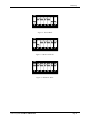
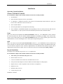
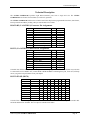
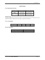
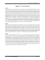
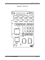
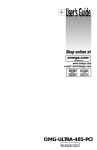
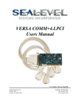
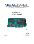
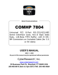
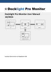
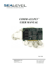
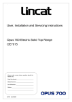
ULTRA COMM+8.PCI
Users Manual
Part Number 7804
Sealevel Systems, Inc.
PO Box 830
Liberty, SC 29657 USA
Telephone: 864.843.4343
Fax: 864.843.3067
www.sealevel.com
Contents
INTRODUCTION ........................................................................................................................ 1
OVERVIEW .............................................................................................................................................. 1
WHAT IS INCLUDED................................................................................................................................. 1
CARD SETUP ............................................................................................................................ 2
ADDRESS AND IRQ SELECTION ............................................................................................................... 2
CLOCK MODES ........................................................................................................................................ 2
BAUD RATES AND OSCILLATOR VALUE................................................................................................... 2
ELECTRICAL INTERFACE SELECTION ....................................................................................................... 3
LINE TERMINATION ................................................................................................................................. 3
RS-485 ‘ECHO’....................................................................................................................................... 3
INSTALLATION ......................................................................................................................... 5
OPERATING SYSTEM INSTALLATION ....................................................................................................... 5
Windows 95/98/ME/NT/2000/XP....................................................................................................... 5
Linux ................................................................................................................................................... 5
QNX .................................................................................................................................................... 5
PHYSICAL INSTALLATION ........................................................................................................................ 5
TECHNICAL DESCRIPTION....................................................................................................... 6
RS-422/485 (CA-145 DB-9) CONNECTOR PIN ASSIGNMENTS ................................................................ 6
RS-232 (CA-145 DB-9) CONNECTOR PIN ASSIGNMENTS ....................................................................... 6
RS-232/422/485 (DB-78) ....................................................................................................................... 6
SPECIFICATIONS ...................................................................................................................... 7
ENVIRONMENTAL SPECIFICATIONS ......................................................................................................... 7
MANUFACTURING ................................................................................................................................... 7
POWER CONSUMPTION ............................................................................................................................ 7
PHYSICAL DIMENSIONS ........................................................................................................................... 7
APPENDIX A - TROUBLESHOOTING ......................................................................................... 8
APPENDIX B - HOW TO GET ASSISTANCE .............................................................................. 9
APPENDIX C - ELECTRICAL INTERFACE ............................................................................... 10
RS-232 ................................................................................................................................................. 10
RS-422 ................................................................................................................................................. 10
RS-485 ................................................................................................................................................. 10
APPENDIX D - ASYNCHRONOUS COMMUNICATIONS ............................................................ 11
APPENDIX E - SILK-SCREEN.................................................................................................. 12
APPENDIX F - COMPLIANCE NOTICES .................................................................................. 13
FEDERAL COMMUNICATIONS COMMISSION STATEMENT ....................................................................... 13
EMC DIRECTIVE STATEMENT ............................................................................................................... 13
WARRANTY ............................................................................................................................ 14
©Sealevel Systems, Inc.
SL9068 Revision 5/2007
Sealevel Systems, Incorporated. All rights reserved.
Introduction
Introduction
Overview
The Sealevel ULTRA COMM+8.PCI is an eight channel RS-232/485/422 PCI Bus serial I/O adapter supporting
data rates up to 921.6Kbps.
The RS-232 compatibility allows for connection to devices utilizing the RS-232 electrical interface, such as
modems, data-entry terminals, and plotters.
RS-422 provides excellent communications for long distance device connections up to 4000ft., where noise
immunity and high data integrity are essential.
RS-485 is optimized for ‘Multi-Drop’ or ‘Party-line’ operations selecting data from multiple peripherals (as many as
31 devices can be connected on an RS-485 bus).
In both RS-485 and RS-422 modes, the card works seamlessly with the standard operating system serial driver. In
RS-485 mode, our special auto-enable feature allows the RS-485 ports to be viewed by the operating system as a
COM: port. This allows the standard COM: driver to be utilized for RS-485 communications. Our on-board
hardware automatically handles the RS-485 driver enable.
The ULTRA COMM+8.PCI also features Universal Bus (3.3 and 5.0V) operation.
What is Included
The ULTRA COMM+8.PCI is shipped with the following items. If any of these items is missing or damaged,
contact the supplier.
•
•
•
ULTRA COMM+8.PCI Serial I/O Adapter
CA145
Sealevel Software CD
Sealevel Systems ULTRA COMM+8.PCI
Page 1
Card Setup
Card Setup
Address and IRQ selection
The ULTRA COMM+8.PCI is automatically assigned I/O addresses and IRQs by your motherboard BIOS or by a
‘Plug-n-Play’ Operating System. Adding or removing other hardware or moving the adapter to another slot may
change the assignment of I/O addresses and IRQs.
Clock Modes
The Ultra COMM+8.PCI employs a unique clocking option that allows the end user to select from divide by 8 and
divide by 1 clocking modes. This mode is selected at S9.
To select the Baud rates commonly associated with COM: ports (i.e. 2400, 4800, 9600, 19.2,…115.2K Bps) place
the switch to the divide by 8 (Silkscreen - D8). In this mode the standard 14.7456 MHz oscillator is divided by 8
resulting in 1.8432Mhz, which provides standard COM: port frequencies.
To select the higher data rates place the switch to the divide by 1 (Silkscreen – D1). In this position all data rates
are 8 times the configured rate.
Baud Rates and Oscillator value
The following table shows some common data rates and the rates you should choose to achieve them when using
the ULTRA COMM+8.PCI in the D1 mode. If the O/S of choice is Windows 95/98/ME/2000/NT/XP, the
oscillator value (14.7456 MHz) should entered into the ‘Advanced Tab’ on 95/98/Me/2000/XP Device Manager
applet. When using Windows NT, the ‘Advanced Ports’ applet in the Control Panel should be launched and the
oscillator value may be entered in the ‘Advanced’ tab. When using any other OS (i.e. Linux, or QNX) the following
tables should be used.
For this Data Rate
1200 bps
2400 bps
4800 bps
9600 bps
19.2K bps
38.4K bps
115.2K bps
230.4K bps
460.8K bps
921.6K bps
Choose this Data Rate
150 bps
300 bps
600 bps
1200 bps
2400 bps
4800 bps
14.4K bps
28.8K bps
57.6 K bps
115.2 K bps
If your communications package allows the use of Baud rate divisors, choose the appropriate divisor from the
following table:
For this Data Rate
Choose this Divisor
1200 bps
768
2400 bps
384
4800 bps
192
9600 bps
96
19.2K bps
48
38.4K bps
24
57.6K bps
16
115.2K bps
8
230.4K bps
4
460.8K bps
2
921.6K bps
1
Sealevel Systems ULTRA COMM+8.PCI
Page 2
Card Setup
Electrical Interface Selection
Each of the eight ports on the ULTRACOMM+8.PCI can be individually configured as an RS-232, RS-422, or
RS-485 interface. This is selectable via the port DIP-switch, each is labeled with its port number (i.e. S1 = Port1, S2
= Port2 etc.)
Switch 1 (Silk M1)
OFF
OFF
ON
ON
Switch 2 (Silk M0)
OFF
ON
OFF
ON
Mode Select
232
422
485 With Echo
458 No Echo
Line Termination
Typically, each end of the RS-485 bus must have line-terminating resistors (RS-422 terminates at the receive end
only). A 120-ohm resistor is across each RS-422/485 input in addition to a 1K-ohm pull-up/pull-down combination
that biases the receiver inputs. Switch SW1 allows customization of this interface to specific requirements. Each
switch position corresponds to a specific portion of the interface. If multiple ULTRA COMM+8.PCI adapters are
configured in an RS-485 network, only the boards on each end should have switches T, P & P ON. Refer to the
following table for each position’s operation:
Switch
3
4
5
6
7
Name
T
PU
PD
L
L
Function
Adds or removes the 120 ohm termination.
Adds or removes the 1K ohm pull-up resistor in the RS-422/RS-485 receiver circuit
Adds or removes the 1K ohm pull-down resistor in the RS-422/RS-485 receiver circuit
Connects the TX- to RX- for RS-485 two-wire operation.
Connects the TX+ to RX+ for RS-485 two-wire operation.
RS-485 ‘Echo’
The RS-485 ‘Echo’ is the result of connecting the receiver inputs to the transmitter outputs. Every time a character
is transmitted; it is also received. This can be beneficial if the software can handle echoing (i.e. using received
characters to throttle the transmitter) or it can confuse the system if the software does not. An RS-485 ‘No Echo’
option is selected by placing both Mode switches (M0, M1) in the ‘On’ position.
ON
1 2 3 4 5 6 7
Figure 1 - RS-232 Mode
Sealevel Systems ULTRA COMM+8.PCI
Page 3
Card Setup
ON
1 2 3 4 5 6 7
Figure 2 - RS-422 Mode
ON
1 2 3 4 5 6 7
Figure 3 - RS-485 with 'Echo'
ON
1 2 3 4 5 6 7
Figure 4 - RS-485 No 'Echo'
Sealevel Systems ULTRA COMM+8.PCI
Page 4
Installation
Installation
Operating System Installation
Windows 95/98/ME/NT/2000/XP
Do not install the Adapter in the machine until the software has been fully installed.
1.
Start Windows.
2.
Insert the Sealevel Systems CD in to your CD drive.
3.
If ‘Auto-Start’ is enabled for this drive the software will automatically launch. Otherwise, point your
browser to the ‘Index.htm’ on the root of the CD
4.
Select ‘Install Software’.
5.
Select the part number for your adapter from the listing.
6.
Select ‘Windows 95/98/ME/NT/2000/XP’ then (depending on the OS version) select the ‘Run from the
current location’ or ‘Open’ option. Follow the information presented on the screens that follow.
Linux
Refer to D:\software\seacom\Other\Linux\Linux.Serial.Readme (where D: = your CDROM driver letter) found on
the Sealevel Systems CD. This file contains valuable information on installing your adapter in the various Linux
releases. Also in this sub-directory is the Linux SerialHOWTO. This series of files explains typical Linux serial
implementations, as well as informing the user to Linux syntax and preferred practices.
QNX
Refer to D:\software\seacom\Other\QNX6\Install.readme (where D: = your CDROM driver letter) found on the
Sealevel Systems CD. This file contains valuable information on installing your adapter in the QNX6 Neutrino OS,
as well as the files required to ensure a flawless implementation. Also provided on the Sealevel Systems CD are
implementation instructions for QNX4. These are found in D:\software\seacom\Other\QNX4\QNX_COM.txt.
Physical Installation
The adapter can be installed in any PCI (5V or 3.3 V) expansion slot.
Do not install the Adapter in the machine until the software has been fully installed.
1.
Turn off PC power. Disconnect the power cord.
2.
Remove the PC case cover.
3.
Locate an available PCI slot and remove the blank metal slot cover.
4.
Gently insert the PCI adapter into the slot. Make sure that the adapter is seated properly.
5.
Replace the screw. (This is required to ensure FCC Part 15 compliance.)
6.
Replace the cover.
7.
Install the cable (CA-199)
8.
Connect the power cord
Installation is finished.
Sealevel Systems ULTRA COMM+8.PCI
Page 5
Technical Description
Technical Description
The ULTRA COMM+8.PCI provides eight RS-232/422/485 ports from a single PCI slot. The ULTRA
COMM+8.PCI also features Universal Bus (3.3 and 5.0V) operation.
The ULTRA COMM+8.PCI utilizes the 16C864 UART. This chip features programmable baud rates, data format,
interrupt control and industry leading 128-byte transmit and receive FIFOs.
RS-422/485 (CA-145 DB-9) Connector Pin Assignments
Signal
GND
TX +
TXRTS+
RTSRX+
RXCTS+
CTS-
Name
Ground
Transmit Data Positive
Transmit Data Negative
Request To Send Positive
Request To Send Negative
Receive Data Positive
Receive Data Negative
Clear To Send Positive
Clear To Send Negative
Pin #
5
4
3
6
7
1
2
9
8
Mode
Output
Output
Output
Output
Input
Input
Input
Input
RS-232 (CA-145 DB-9) Connector Pin Assignments
Signal
Name
Pin #
Mode
GND
Ground
5
TD
Transmit Data
3
Output
RTS
Request To Send
7
Output
DTR
Data Terminal Ready
4
Output
RD
Receive Data
2
Input
CTS
Clear To Send
8
Input
DSR
Data Set Ready
6
Input
DCD
Data Carrier Detect
1
Input
RI
Ring Indicator
9
Input
Technical Note: Please terminate any control signals that are not going to be used. The most common way to do this
is connect RTS to CTS and RI. Also, connect DCD to DTR and DSR. Terminating these pins, if not used, will help
ensure you get the best performance from your adapter.
RS-232/422/485 (DB-78)
Port #
1
2
3
4
5
6
7
8
RS-422/485
RS-232
TXTD
36
12 27
3
75 51 66
42
RXRD
37
11 28
2
76 50 67
41
RTSRTS
17
31
8
22 56 70 47
61
CTSCTS
16
32
7
23 55 71 46
62
TX+
DTR
35
13 26
4
74 52 65
43
RTS+
DSR
18
30
9
21 57 69 48
60
RX+
DCD
38
10 29
1
77 49 68
40
CTS+
RI
15
33
6
24 54 72 45
63
GND
GND
34
14 25
5
73 53 64
44
Technical Note: The RTS output is only available in RS-232 and RS-422 modes. The RTS output is tri-stated in RS485 mode and therefore unusable. The CTS input is available in all modes.
Sealevel Systems ULTRA COMM+8.PCI
Page 6
Specifications
Specifications
Environmental Specifications
Specification
Temperature
Range
Humidity Range
Operating
0º to 70º C
(32º to 158º F)
10 to 90% R.H.
Non-Condensing
Storage
-50º to 105º C
(-58º to 221º F)
10 to 90% R.H.
Non-Condensing
Manufacturing
All Sealevel Systems Printed Circuit boards are built to UL 94V0 rating and are 100% electrically tested. These
printed circuit boards are solder mask over bare copper or solder mask over tin nickel.
Power Consumption
Supply line
Rating
+3.3VDC
200 mA
+5VDC
400 mA
+12VDC
32 mA
-12VDC
30 mA
Physical Dimensions
Board length
Board Height including Goldfingers
Board Height excluding Goldfingers
Sealevel Systems ULTRA COMM+8.PCI
6.5 inches
4.2 inches
3.875 inches
(16.51 cm.)
(10.67 cm.)
(9.84 cm.)
Page 7
Appendix A - Troubleshooting
Appendix A - Troubleshooting
1.
Identify all I/O adapters currently installed in your system. This includes your on-board serial ports, controller
cards, sound cards etc. The I/O addresses used by these adapters, as well as the IRQ (if any) should be
identified.
2.
Configure your Sealevel Systems adapter so that there is no conflict with currently installed adapters. No two
adapters can occupy the same I/O address.
3.
Make sure the Sealevel Systems adapter is using a unique IRQ. While the Sealevel Systems adapter does allow
the sharing of IRQs, many other adapters (i.e. SCSI adapters & on-board serial ports) do not. The IRQ is
typically selected by the BIOS or operating system. Some BIOS setup software will allow changing the IRQ,
but others do not. Another method of changing assigned resources is to try changing PCI slots. This will
typically cause the BIOS or OS to reassign the resources.
4.
Make sure the Sealevel Systems adapter is securely installed in a motherboard slot.
5.
When running DOS or Windows 3.x refer to the supplied Sealevel Software and this User Manual to verify that
the Sealevel Systems adapter is configured correctly. This software contains a diagnostic program ‘SSD’
(D:\software\seacom\Other\DOS\DIAG, where D: = the driver letter of your CDROM drive) will verify if an
adapter is configured properly. This diagnostic program is written with the user in mind and is easy to use. You
can use D:\software\seacom\Other\DOS\PCI\FindPCI.exe to determine resources that have been assigned to
your adapter. Make sure that if available, the ‘Use Plug-n-Play” option is turned ‘OFF’ in your BIOS. Having
this option set to ‘ON’ in DOS or Windows 3.x will cause erratic operations.
6.
For Windows95/98/ME/NT/2000, the diagnostic tool ‘WinSSD’ is installed in the SeaCOM folder on the Start
Menu during the setup process. First find the ports using the Device Manager, then use ‘WinSSD’ to verify that
the ports are functional.
7.
Always use the Sealevel Systems diagnostic software when troubleshooting a problem. This will eliminate any
software issues from the equation.
Sealevel Systems ULTRA COMM+8.PCI
Page 8
Appendix B - How To Get Assistance
Appendix B - How To Get Assistance
Please refer to Troubleshooting Guide prior to calling Technical Support.
1.
Begin by reading through the Trouble Shooting Guide in Appendix A. If assistance is still needed
please see below.
2.
When calling for technical assistance, please have your user manual and current adapter settings. If
possible, please have the adapter installed in a computer ready to run diagnostics.
3.
Sealevel Systems provides an FAQ section on its web site. Please refer to this to answer many
common questions. This section can be found at http://www.sealevel.com/faq.asp.
4.
Sealevel Systems maintains a web page on the Internet. Our home page address is www.sealevel.com.
The latest software updates, and newest manuals are available via our web site.
5.
Technical support is available Monday to Friday from 8:00 a.m. to 5:00 p.m. eastern time. Technical
support can be reached at (864) 843-4343.
Return Authorization Must Be Obtained From Sealevel Systems Before Returned Merchandise Will Be
Accepted. Authorization Can Be Obtained By Calling Sealevel Systems And Requesting A Return
Merchandise Authorization (RMA) Number.
Sealevel Systems ULTRA COMM+8.PCI
Page 9
Appendix C - Electrical Interface
Appendix C - Electrical Interface
RS-232
Quite possibly the most widely used communication standard is RS-232. This implementation has been defined and
revised several times and is often referred to as RS-232-C/D/E or EIA/TIA-232-C/D/E. It is defined as “Interface
between Data Terminal Equipment and Data Circuit- Terminating Equipment Employing Serial Binary Data
Interchange”. The mechanical implementation of RS-232 is on a 25-pin D sub connector. The IBM PC computer
defined the RS-232 port on a 9 pin D sub connector and subsequently the EIA/TIA approved this implementation as
the EIA/TIA-574 standard. This standard has defined as the “9-Position Non-Synchronous Interface between Data
Terminal Equipment and Data Circuit-Terminating Equipment Employing Serial Binary Data Interchange”. Both
implementations are in wide spread use and will be referred to as RS-232 in this document. RS-232 is capable of
operating at data rates up to 20K bps / 50 ft. The absolute maximum data rate may vary due to line conditions and
cable lengths. RS-232 often operates at 38.4K bps over very short distances. The voltage levels defined by RS-232
range from -12 to +12 volts. RS-232 is a single ended or unbalanced interface, meaning that a single electrical
signal is compared to a common signal (ground) to determine binary logic states. A voltage of +12 volts (usually +3
to +10 volts) represents a binary 0 (space) and -12 volts (-3 to -10 volts) denote a binary 1 (mark). The RS-232 and
the EIA/TIA-574 specification define two types of interface circuits Data Terminal Equipment (DTE) and Data
Circuit-Terminating Equipment (DCE). The Sealevel Systems Adapter is a DTE interface.
RS-422
The RS-422 specification defines the electrical characteristics of balanced voltage digital interface circuits. RS-422
is a differential interface that defines voltage levels and driver/receiver electrical specifications. On a differential
interface, logic levels are defined by the difference in voltage between a pair of outputs or inputs. In contrast, a
single ended interface, for example RS-232, defines the logic levels as the difference in voltage between a single
signal and a common ground connection. Differential interfaces are typically more immune to noise or voltage
spikes that may occur on the communication lines. Differential interfaces also have greater drive capabilities that
allow for longer cable lengths. RS-422 is rated up to 10 Megabits per second and can have cabling 4000 feet long.
RS-422 also defines driver and receiver electrical characteristics that will allow 1 driver and up to 32 receivers on
the line at once. RS-422 signal levels range from 0 to +5 volts. RS-422 does not define a physical connector.
RS-485
RS-485 is backwardly compatible with RS-422; however, it is optimized for party line or multi-drop applications.
The output of the RS-422/485 driver is capable of being Active (enabled) or Tri-State (disabled). This capability
allows multiple ports to be connected in a multi-drop bus and selectively polled. RS-485 allows cable lengths up to
4000 feet and data rates up to 10 Megabits per second. The signal levels for RS-485 are the same as those defined
by RS-422. RS-485 has electrical characteristics that allow for 32 drivers and 32 receivers to be connected to one
line. This interface is ideal for multi-drop or network environments. RS-485 tri-state driver (not dual-state) will
allow the electrical presence of the driver to be removed from the line. Only one driver may be active at a time and
the other driver(s) must be tri-stated. RS-485 can be cabled in two ways, two wire and four wire mode. Two-wire
mode does not allow for full duplex communication, and requires that data be transferred in only one direction at a
time. For half-duplex operation, the two transmit pins should be connected to the two receive pins (Tx+ to Rx+ and
Tx- to Rx-). Four wire mode allows full duplex data transfers. RS-485 does not define a connector pin-out or a set
of modem control signals. RS-485 does not define a physical connector.
Sealevel Systems ULTRA COMM+8.PCI
Page 10
Appendix D - Asynchronous Communications
Appendix D - Asynchronous Communications
Serial data communications implies that individual bits of a character are transmitted consecutively to a receiver that
assembles the bits back into a character. Data rate, error checking, handshaking, and character framing (start/stop
bits) are pre-defined and must correspond at both the transmitting and receiving ends.
Asynchronous communications is the standard means of serial data communication for PC compatibles and PS/2
computers. The original PC was equipped with a communication or COM: port that was designed around an 8250
Universal Asynchronous Receiver Transmitter (UART). This device allows asynchronous serial data to be
transferred through a simple and straightforward programming interface. A starting bit followed by a pre-defined
number of data bits (5, 6, 7, or 8) defines character boundaries for asynchronous communications. The end of the
character is defined by the transmission of a pre-defined number of stop bits (usually 1, 1.5 or 2). An extra bit used
for error detection is often appended before the stop bits.
Idle state of
line
5 to 8 Data Bits
Odd, Even
or
Unused
Remain Idle or
next start bit
1
P
BIT
STOP
0
1
1.5
2
Figure 5 - Asynchronous Communications Bit Diagram
This special bit is called the parity bit. Parity is a simple method of determining if a data bit has been lost or
corrupted during transmission. There are several methods for implementing a parity check to guard against data
corruption. Common methods are called (E)ven Parity or (O)dd Parity. Sometimes parity is not used to detect errors
on the data stream. This is refereed to as (N)o parity. Because each bit in asynchronous communications is sent
consecutively, it is easy to generalize asynchronous communications by stating that each character is wrapped
(framed) by pre-defined bits to mark the beginning and end of the serial transmission of the character. The data rate
and communication parameters for asynchronous communications have to be the same at both the transmitting and
receiving ends. The communication parameters are baud rate, parity, number of data bits per character, and stop bits
(i.e. 9600,N,8,1).
Sealevel Systems ULTRA COMM+8.PCI
Page 11
Appendix E - Silk-Screen
Appendix E - Silk-Screen
Sealevel Systems ULTRA COMM+8.PCI
Page 12
Appendix F - Compliance Notices
Appendix F - Compliance Notices
Federal Communications Commission Statement
FCC - This equipment has been tested and found to comply with the limits for Class A digital device, pursuant to
Part 15 of the FCC Rules. These limits are designed to provide reasonable protection against harmful interference
when the equipment is operated in a commercial environment. This equipment generates, uses, and can radiate radio
frequency energy and, if not installed and used in accordance with the instruction manual, may cause harmful
interference to radio communications. Operation of this equipment in a residential area is likely to cause harmful
interference in such case the user will be required to correct the interference at the users expense.
EMC Directive Statement
Products bearing the CE Label fulfill the requirements of the EMC directive (89/336/EEC) and of
the low-voltage directive (73/23/EEC) issued by the European Commission.
To obey these directives, the following European standards must be met:
EN55022 Class A - “Limits and methods of measurement of radio interference characteristics of
information technology equipment”
EN55024 – “Information technology equipment Immunity characteristics Limits and methods of
measurement”.
EN60950 (IEC950) - “Safety of information technology equipment, including electrical business
equipment”
Warning
This is a Class A Product. In a domestic environment, this product may cause radio interference in which
case the user may be required to take adequate measures to prevent or correct the interference.
Always use cabling provided with this product if possible. If no cable is provided or if an alternate cable is required,
use high quality shielded cabling to maintain compliance with FCC/EMC directives.
Sealevel Systems ULTRA COMM+8.PCI
Page 13
Warranty
Warranty
Sealevel's commitment to providing the best I/O solutions is reflected in the Lifetime
Warranty that is standard on all Sealevel manufactured products. We are able to offer
this warranty due to our control of manufacturing quality and the historically high
reliability of our products in the field. Sealevel products are designed and
manufactured at its Liberty, South Carolina facility, allowing direct control over
product development, production, burn-in and testing.
Sealevel Systems, Inc. (hereafter "Sealevel") warrants that the Product shall conform to and perform in accordance
with published technical specifications and shall be free of defects in materials and workmanship for life. In the
event of failure, Sealevel will repair or replace the product at Sealevel's sole discretion. Failures resulting from
misapplication or misuse of the Product, failure to adhere to any specifications or instructions, or failure resulting
from neglect or abuse are not covered under this warranty.
Warranty service is obtained by delivering the Product to Sealevel and providing proof of purchase. Return
authorization must be obtained from Sealevel Systems before returned merchandise will be accepted.
Authorization is obtained by calling Sealevel Systems and requesting a Return Merchandise Authorization
(RMA) number. The Customer agrees to insure the Product or assume the risk of loss or damage in transit, to
prepay shipping charges to Sealevel, and to use the original shipping container or equivalent. Warranty is valid only
for original purchaser and is not transferable.
Sealevel Systems assumes no liability for any damages, lost profits, lost savings or any other incidental or
consequential damage resulting from the use, misuse of, or inability to use this product. Sealevel Systems will not
be liable for any claim made by any other related party.
This warranty applies to Sealevel manufactured Product. Product purchased through Sealevel but manufactured by a
third party will retain the original manufacturer's warranty.
Sealevel Systems, Incorporated
2779 Greenville Highway
P.O. Box 830
Liberty, SC 29657 USA
(864) 843-4343 FAX: (864) 843-3067
www.sealevel.com
email: [email protected]
Technical Support is available from 8 a.m. to 5 p.m. Eastern time.
Monday - Friday
Trademarks
Sealevel Systems, Incorporated acknowledges that all trademarks referenced in this manual are the service mark,
trademark, or registered trademark of the respective company.
ULTRA COMM+8.PCI is a trademark of Sealevel Systems, Incorporated.
Sealevel Systems ULTRA COMM+8.PCI
Page 14