1
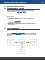
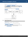
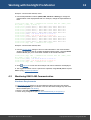
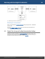
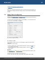
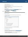
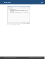
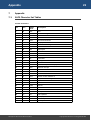
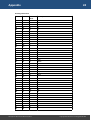
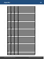
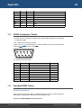
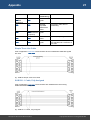
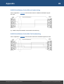
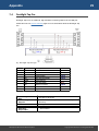
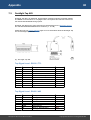
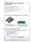
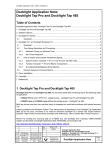
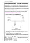
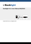
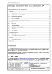
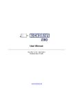
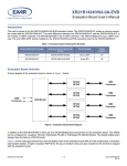
Docklight Pro Monitor User Manual
10/2015
Copyright 2015 Flachmann und Heggelbacher GbR
2
Table of Contents
1.
Copyright
4
2.
Welcome to Docklight Pro Monitor
5
2.1
Docklight Pro Monitor - Overview ............................................................................... 6
2.2
Typical Hardware Setups ............................................................................................... 6
2.3
System Requirements .................................................................................................... 7
3.
User Interface
8
3.1
Main Window ................................................................................................................. 9
3.2
Clipboard - Copy & Paste ............................................................................................. 10
4.
Working with Docklight Pro Monitor
11
4.1
Monitoring RS232 Communication ............................................................................ 12
4.2
Monitoring RS422-485 Communication ..................................................................... 13
4.3
Project Files: Saving and Loading Communication Settings .................................... 14
5.
Reference
15
5.1
Menu ............................................................................................................................. 16
5.2
Toolbar .......................................................................................................................... 16
5.3
Content Filter ............................................................................................................... 16
5.4
Dialog: Channel Configuration .................................................................................... 17
5.5
Dialog: Options ............................................................................................................. 18
6.
Support
20
6.1
Web Support and Troubleshooting ........................................................................... 21
6.2
E-Mail Support ............................................................................................................. 21
7.
Appendix
22
7.1
ASCII Character Set Tables ........................................................................................... 23
7.2
RS232 Connectors / Pinout ......................................................................................... 26
7.3
Standard RS232 Cables ................................................................................................ 26
7.4
Docklight Tap Pro ........................................................................................................ 29
7.5
Docklight Tap 485 ........................................................................................................ 30
8.
Glossary / Terms Used
32
8.1
Break State ................................................................................................................... 33
8.2
Character ...................................................................................................................... 33
8.3
CTS ................................................................................................................................. 33
8.4
DCD ................................................................................................................................ 33
8.5
DCE ................................................................................................................................ 33
Docklight Pro Monitor User Manual 10/2015
Copyright 2015 Flachmann und Heggelbacher GbR
3
Table of Contents
8.6
DSR ................................................................................................................................ 34
8.7
DTE ................................................................................................................................ 34
8.8
DTR ................................................................................................................................ 34
8.9
Flow Control ................................................................................................................. 34
8.10
FTDI device drivers ....................................................................................................... 35
8.11
LIN ................................................................................................................................. 35
8.12
MODBUS ....................................................................................................................... 35
8.13
Multidrop Bus (MDB) ................................................................................................... 35
8.14
RI .................................................................................................................................... 35
8.15
RS232 ............................................................................................................................. 36
8.16
RS422 ............................................................................................................................. 36
8.17
RS485 ............................................................................................................................. 37
8.18
RTS ................................................................................................................................. 37
8.19
UART .............................................................................................................................. 37
Docklight Pro Monitor User Manual 10/2015
Copyright 2015 Flachmann und Heggelbacher GbR
4
Copyright
1
Copyright
Copyright 2015 Flachmann und Heggelbacher GbR
All rights reserved. No parts of this work may be reproduced in any form or by any
means - graphic, electronic, or mechanical, including photocopying, recording, taping, or
information storage and retrieval systems - without the written permission of the
publisher.
Trademarks
Products that are referred to in this document may be either trademarks and/or
registered trademarks of the respective owners. The publisher and the author make no
claim to these trademarks.
Microsoft and Windows are either registered trademarks or trademarks of Microsoft
Corporation in the United States and/or other countries.
Disclaimer
While every precaution has been taken in the preparation of this document, the publisher
and the author assume no responsibility for errors or omissions, or for damages resulting
from the use of information contained in this document or from the use of programs and
source code that may accompany it. In no event shall the publisher and the author be
liable for any loss of profit or any other commercial damage caused or alleged to have
been caused directly or indirectly by this document.
Contact
E-Mail Support: [email protected]
Flachmann & Heggelbacher
Waldkirchbogen 27
D-82061 Neuried
Germany
http://www.fuh-edv.de
Docklight Pro Monitor User Manual 10/2015
Copyright 2015 Flachmann und Heggelbacher GbR
Welcome to Docklight Pro Monitor
6
Welcome to Docklight Pro Monitor
2
Welcome to Docklight Pro Monitor
2.1
Docklight Pro Monitor - Overview
Docklight Pro Monitor is a Windows tool for high speed and high resolution serial
communications monitoring (RS232, RS422 and RS485).
It is designed to work with the Docklight Tap Pro and Docklight Tap 485 devices. Both,
Tap Pro and Tap 485 use their own high resolution hardware time base for all serial data
and serial line events monitored.
Key functions include
· Logging RS232 or RS485/422 serial data - Serial communication data can be
logged and displayed in different representations: ASCII, Hexadecimal, Decimal and
Binary. High-speed, flexible output formatting for both binary data and text-based
protocols, including control characters.
· Logging RS232 serial line states - Status Line / Handshake signals (RTS, DTR,
CTS, DSR, DCR, RI) and Break State.
· High performance and high accuracy monitoring - real-time data acquisition with
milliseconds precision.
· Real-time filtering - hide/show logged data by type or source, while the
communication is running.
2.2
Typical Hardware Setups
Monitor the communication between PC and device
Connect the Docklight Tap Pro or Docklight Tap 485 hardware between your device and
your PC using at least one RS232 cable. Connect the Tap Pro to a PC running Docklight
Pro Monitor using a USB cable. This can be the same PC used for communicating with
the device.
Once the hardware has been connected, you can start Monitoring Serial
Communication.
fig.: Monitoring the communication between PC and device
Docklight Pro Monitor User Manual 10/2015
Copyright 2015 Flachmann und Heggelbacher GbR
7
Welcome to Docklight Pro Monitor
Monitor the communication between two PCs
Connect the Docklight Tap Pro or Docklight Tap 485 hardware between your two PCs
using a null modem cable ( ! ). This cable is required to crosslink the DTE and DCE
lines for inter-PC communication. Connect the Tap hardware to a PC running Docklight
Pro Monitor using the USB connection. This can be one of the PCs used for
communicating with the device.
Once the hardware has been connected, you can start Monitoring Serial
Communication.
fig.: Monitoring two PCs (null modem cable necessary ! )
2.3
System Requirements
Operating system
· Windows 10, Windows 8, Windows 7, Windows Vista, Windows XP.
Hardware requirements
· Docklight Tap Pro or Docklight Tap 485 for high precision serial monitoring
Additional cables may be required for connecting the equipment to be tested. See the
Appendix Standard RS232 Cables for a description of these cables.
Docklight Pro Monitor User Manual 10/2015
Copyright 2015 Flachmann und Heggelbacher GbR
User Interface
9
User Interface
3
User Interface
3.1
Main Window
fig.: Main Window Layout
1. Menu bar
Use the File menu to open or save a project containing communication settings. Use the
Channels menu to display the channel communication settings dialog. See Dialog:
Channel settings and Project Files: Saving and Loading Communication Data.
2. Toolbar
Common Docklight Pro Monitor functions: Start or Stop communication, Clear the
communication data, display Options, or Help to access this manual.
3. Status
Displays the current status of communication with the Tap Pro device: Idle, Running,
Error, etc.
4. Representation
Possibility to control the format of displayed data: ASCII, Hex, Decimal or Binary.
5. Channels
Shows the current Docklight Tap Pro or Docklight Tap 485 device settings. To change
the settings, click on the [...] buttons or by double clicking on any of the displayed
settings. See Dialog: Channel settings.
6. Content (filtering)
Show or hide different types of content in the communication window. Content filters can
be modified while communication is running. See Main window: Content filter.
7. Format
Docklight Pro Monitor User Manual 10/2015
Copyright 2015 Flachmann und Heggelbacher GbR
10
User Interface
Configure the timestamp format and the appearance of control characters inside the
communication window. Formats can be modified while the communication is running.
See Dialog: Options.
8. Communication Window
Displays all communication data and serial line events monitored by Docklight Tap Pro
or Docklight Tap 485. Communication data can be copied to clipboard by selecting text
with the mouse cursor. See chapter Clipboard for details.
NOTE: The monitored data is stored in a ring buffer. This means that when large
amounts of data are monitored, the oldest displayed data will be overwritten. When this
happens, the status above the communication window will say "ring buffer mode,
overwriting oldest data".
3.2
Clipboard - Copy & Paste
The current Docklight Pro Monitor software does not support logging to file, but Windows
clipboard operations are fully supported in the Communication Window
To copy the complete monitoring data buffer contents, not just the visible part, use either
the right mouse button to display context menu or keyboard shortcuts:
· Ctrl+A (Select All)
then
· Ctrl+C (Copy)
All data is copied in plain text format - colors and fonts are not preserved.
To paste the content to desired application (Microsoft Notepad, Word, Excel,...) use
either the right mouse button to display context menu of this application or use keyboard
shortcut:
· Ctrl+V (Paste)
Docklight Pro Monitor User Manual 10/2015
Copyright 2015 Flachmann und Heggelbacher GbR
Working with Docklight Pro Monitor
12
Working with Docklight Pro Monitor
4
Working with Docklight Pro Monitor
4.1
Monitoring RS232 Communication
Hardware Requirements
· A Docklight Tap Pro or Docklight Tap 485 device to tap serial data and status lines
from both devices.
· The PC running Docklight Pro Monitor must have the latest Docklight Tap Pro USB
drivers installed (see FTDI drivers).
· Device 1 and Device 2 in operational state.
· Correct Cable configuration (see Standard RS232 Cables).
fig.: Monitoring two RS 232 devices
Monitoring the communication
1. Configure the channels according to the communication settings of your device
hardware. To display the Channels Settings Dialog, click on the [...] button in the
Channels section, or choose menu Channels > Configuration.
2. Click
Start to start the communication. Select filter settings in the content section
according to your needs. Your communication window will contain information similar
to this:
16:34:06.090
PC2 (VTP1) @
16:34:06.138
16:34:10.207
16:34:10.207
16:34:15.412
16:34:15.412
16:34:15.463
16:34:15.491
16:34:19.258
16:34:19.259
16:34:23.598
16:34:23.598
16:34:23.598
[App, CFG] - Communication started: Test
(9600, 8, None, 1)
[Status Lines] - RTS=0 DTR=0 CTS=0 DSR=0
[Status Lines] - RTS=0 DTR=0 CTS=1 DSR=0
[Status Lines] - RTS=0 DTR=0 CTS=1 DSR=1
[Status Lines] - RTS=0 DTR=0 CTS=1 DSR=1
[Status Lines] - RTS=0 DTR=1 CTS=1 DSR=1
[VTP0] - ----o Ping
[VTP1] - o---- Pong
[Status Lines] - RTS=0 DTR=0 CTS=1 DSR=1
[Status Lines] - RTS=0 DTR=0 CTS=1 DSR=1
[Status Lines] - RTS=0 DTR=0 CTS=1 DSR=0
[Status Lines] - RTS=0 DTR=0 CTS=0 DSR=0
[App, CFG] - Communication stopped
Docklight Pro Monitor User Manual 10/2015
PC1 (VTP0), Test
DCD=0
DCD=0
DCD=0
DCD=0
DCD=0
RI=0
RI=1
RI=1
RI=1
RI=1
DCD=0
DCD=0
DCD=0
DCD=0
RI=1
RI=1
RI=1
RI=0
Copyright 2015 Flachmann und Heggelbacher GbR
13
Working with Docklight Pro Monitor
Example: communication window, ASCII
3. Use the Representation buttons (ASCII, HEX, Decimal or Binary) to change the
representation of the displayed RX data. For example, change the representation to
HEX.
16:34:06.090
PC2 (VTP1) @
16:34:06.138
16:34:10.207
16:34:10.207
16:34:15.412
16:34:15.412
16:34:15.463
16:34:15.491
16:34:19.258
16:34:19.259
16:34:23.598
16:34:23.598
16:34:30.320
[App, CFG] - Communication started: Test
(9600, 8, None, 1)
[Status Lines] - RTS=0 DTR=0 CTS=0 DSR=0
[Status Lines] - RTS=0 DTR=0 CTS=1 DSR=0
[Status Lines] - RTS=0 DTR=0 CTS=1 DSR=1
[Status Lines] - RTS=0 DTR=0 CTS=1 DSR=1
[Status Lines] - RTS=0 DTR=1 CTS=1 DSR=1
[VTP0] - 2D 2D 2D 2D 6F 20 50 69 6E 67
[VTP1] - 6F 2D 2D 2D 2D 20 50 6F 6E 67
[Status Lines] - RTS=0 DTR=0 CTS=1 DSR=1
[Status Lines] - RTS=0 DTR=0 CTS=1 DSR=1
[Status Lines] - RTS=0 DTR=0 CTS=1 DSR=0
[Status Lines] - RTS=0 DTR=0 CTS=0 DSR=0
[App, CFG] - Communication stopped
PC1 (VTP0), Test
DCD=0
DCD=0
DCD=0
DCD=0
DCD=0
RI=0
RI=1
RI=1
RI=1
RI=1
DCD=0
DCD=0
DCD=0
DCD=0
RI=1
RI=1
RI=1
RI=0
Example: communication window, HEX
4. Use the Content Filter settings to show or hide information in the communication
window. For protocols that do consider handshake signals states, choosing Status
Lines = Off will give you a much better overview on the actual information.
16:34:06.090
PC2 (VTP1) @
16:34:15.463
16:34:15.491
16:34:30.320
5. Click
[App, CFG] - Communication
(9600, 8, None, 1)
[VTP0] - 2D 2D 2D 2D 6F 20
[VTP1] - 6F 2D 2D 2D 2D 20
[App, CFG] - Communication
started: Test PC1 (VTP0), Test
50 69 6E 67
50 6F 6E 67
stopped
Options to control how time stamps and control characters are displayed.
6. The logged information can be copied to the clipboard, using Ctrl+A (Select All) and
Ctrl+C (Copy) clipboard operations.
4.2
Monitoring RS422-485 Communication
Hardware Requirements
· A Docklight Tap 485 device to tap serial data and status lines from both devices.
· The PC running Docklight Pro Monitor must have the latest Docklight Tap Pro USB
drivers installed (see FTDI drivers).
· Device 1 and Device 2 in operational state.
· Correct wiring configuration (see Tap 485 RS422/RS485 pin assignment ).
Docklight Pro Monitor User Manual 10/2015
Copyright 2015 Flachmann und Heggelbacher GbR
14
Working with Docklight Pro Monitor
fig.: Monitoring two RS 422, RS485 devices
Monitoring the communication
NOTE: For RS422/RS485, Channel Configuration setting Tap Signal Level = RS422/485
must be used.
Monitoring of RS422 or RS485 communication works same way as described in the
chapter Monitoring RS232 Communication.
4.3
Project Files: Saving and Loading Communication Settings
Docklight Pro Monitor remembers the channel configuration and display settings used
after closing and re-opening the application. In addition, you can save these settings in a
Docklight Pro Monitor project file (.dockzip), using the File menu.
Docklight Pro Monitor User Manual 10/2015
Copyright 2015 Flachmann und Heggelbacher GbR
Reference
16
Reference
5
Reference
5.1
Menu
File
New Project
Close the current Docklight Pro Monitor project and create a new one with default
communication settings (9600 baud, 8 start bits, 1 stop bit, No Parity).
Open Project
Loads communication settings from a Docklight Pro Monitor project (.dockzip) file.
Save Project / Save Project As...
Save the current communication settings into a Docklight Pro Monitor project (.dockzip)
file.
Exit
Quit Docklight Pro Monitor.
Channels
Configure...
Displays the Channel configuration dialog.
5.2
5.3
Toolbar
Start
Start logging the Tap data
Stop
Stop logging
Clear
Delete the contents of the communication window
Options
Configure the appearance of the logging information:
o Date format
o Time format
o Display of control characters (ASCII)
Content Filter
The filters allow to show or hide information in the communication window. You can
toggle filters while the communication is running. Content types include:
· Timestamp information. A new time stamp is added for each change in data direction,
or with each communication event such as status line changes, or configuration
information.
· Configuration Info, e.g. "Communication started", "Communication stopped".
· Data. The two communication data directions can also be filtered individually using the
On/Off switches in the Channels area.
Docklight Pro Monitor User Manual 10/2015
Copyright 2015 Flachmann und Heggelbacher GbR
17
Reference
· Status lines (RTS, DTR, CTS, DSR, DCD, RI)
· Break State
· Errors
NOTE: The communication data buffer and the accumulated communication data is not
modified when changing content filter settings. Only the communication window display
changes.
5.4
Dialog: Channel Configuration
Configure your Docklight Tap Pro or Docklight Tap 485 serial communication parameters
for your RS232, RS422 or RS485 monitoring.
To open the Channel Configuration dialog, click either Edit (...) in the Channels section
or choose the menu Channels -> Configure.
fig.: Channel configuration dialog
Ch. 1 Alias, Ch. 2 Alias
Enter alternative channel names for your data logging to replace the default values:
VTP0, VTP1.
Consider the channel mapping:
· Channel 1 (default VTP0) - Tap Pro SUB D9 female side, connects to a DTE (e.g. a
PC or a master control device)
· Channel 2 (default VTP1) - Tap Pro SUB D9 male side, connects to a DCE (e.g. a
modem device)
Baud Rate
The Docklight Tap Pro and Docklight Tap 485 hardware supports baud rates from 300
bps to 921.6 kps.
Standard baud rates are available from the dropdown list:
300, 600, 1200, 2400, 4800, 9600, 19200, 28800, 38400, 56000, 57600, 115200,
Docklight Pro Monitor User Manual 10/2015
Copyright 2015 Flachmann und Heggelbacher GbR
18
Reference
230400, 460800, 921600
Custom baud rates can be typed in directly.
Data Bits, Parity, Stop Bits
Check your serial data link carefully for the correct settings, especially Parity. Standard
settings are
8 Data Bits, 1 Stop Bit, Parity = None.
Tap Signal Level
Most applications will work with either standard RS232 voltage levels, or TTL voltage
levels. Docklight Tap Pro and Docklight Tap 485 support both 3.3V and 5V TTL.
The RS422/485 setting only applies to Docklight Tap 485.
5.5
Dialog: Options
Date / Timestamp
You can choose the format of date and timestamp in the communication window
according to your needs.
fig.: Options dialog - Date/Timestamp
Control Characters
Non-printable control characters (ASCII code 0-31, see ASCII Character Set Tables) are
usually invisible or undefined character in ASCII mode.
To visualize these characters in ASCII mode you can choose following options:
· Activate the character description
· In addition you can suppress the original ASCII interpretation
Docklight Pro Monitor User Manual 10/2015
Copyright 2015 Flachmann und Heggelbacher GbR
Reference
19
fig.: Options dialog - Control characters
Docklight Pro Monitor User Manual 10/2015
Copyright 2015 Flachmann und Heggelbacher GbR
Support
21
Support
6
Support
6.1
Web Support and Troubleshooting
For up-to-date FAQs and troubleshooting information, see our online support pages
available at
http://docklight.de/support/
NOTE: Docklight Pro Monitor is a new member of our Docklight family, so if you cannot
find specific information on our website, please do not hesitate to contact us directly.
6.2
E-Mail Support
We provide individual e-mail support to our registered customers. We will contact you as
soon as possible to find a solution to your problem. Send your support request to
[email protected]
Docklight Pro Monitor User Manual 10/2015
Copyright 2015 Flachmann und Heggelbacher GbR
Appendix
23
Appendix
7
Appendix
7.1
ASCII Character Set Tables
Control Characters
Dec
Hex
ASCII
Char.
Description
0
00
NUL
Null
1
01
SOH
Start of heading
2
02
STX
Start of text
3
03
ETX
Break/end of text
4
04
EOT
End of transmission
5
05
ENQ
Enquiry
6
06
ACK
Positive acknowledgment
7
07
BEL
Bell
8
08
BS
Backspace
9
09
HT
Horizontal tab
10
0A
LF
Line feed
11
0B
VT
Vertical tab
12
0C
FF
Form feed
13
0D
CR
Carriage return
14
0E
SO
Shift out
15
0F
SI
Shift in/XON (resume output)
16
10
DLE
Data link escape
17
11
DC1
XON - Device control character 1
18
12
DC2
Device control character 2
19
13
DC3
XOFF - Device control character 3
20
14
DC4
Device control character 4
21
15
NAK
Negative Acknowledgment
22
16
SYN
Synchronous idle
23
17
ETB
End of transmission block
24
18
CAN
Cancel
25
19
EM
End of medium
26
1A
SUB
substitute/end of file
27
1B
ESC
Escape
28
1C
FS
File separator
29
1D
GS
Group separator
30
1E
RS
Record separator
31
1F
US
Unit separator
Docklight Pro Monitor User Manual 10/2015
Copyright 2015 Flachmann und Heggelbacher GbR
24
Appendix
Printing Characters
Dec
Hex
ASCII
Char.
Description
32
20
33
21
!
!
34
22
"
"
35
23
#
#
36
24
$
$
37
25
%
%
38
26
&
&
39
27
'
'
40
28
(
(
41
29
)
)
42
2A
*
*
43
2B
+
+
44
2C
,
,
45
2D
-
-
46
2E
.
.
47
2F
/
/
48
30
0
Zero
49
31
1
One
50
32
2
Two
51
33
3
Three
52
34
4
Four
53
35
5
Five
54
36
6
Six
55
37
7
Seven
56
38
8
Eight
57
39
9
Nine
58
3A
:
:
59
3B
;
;
60
3C
<
<
61
3D
=
=
62
3E
>
>
63
3F
?
?
64
40
@
@
65
41
A
A
66
42
B
B
67
43
C
C
68
44
D
D
69
45
E
E
70
46
F
F
71
47
G
G
72
48
H
H
73
49
I
I
Space
Docklight Pro Monitor User Manual 10/2015
Copyright 2015 Flachmann und Heggelbacher GbR
25
Appendix
74
4A
J
J
75
4B
K
K
76
4C
L
L
77
4D
M
M
78
4E
N
N
79
4F
O
O
80
50
P
P
81
51
Q
Q
82
52
R
R
83
53
S
S
84
54
T
T
85
55
U
U
86
56
V
V
87
7
W
W
88
58
X
X
89
59
Y
Y
90
5A
Z
Z
91
5B
[
[
92
5C
\
\
93
5D
]
]
94
5E
^
^
95
5F
_
_
96
60
`
`
97
61
a
a
98
62
b
b
99
63
c
c
100
64
d
d
101
65
e
e
102
66
f
f
103
67
g
g
104
68
h
h
105
69
i
i
106
6A
j
j
107
6B
k
k
108
6C
l
l
109
6D
m
m
110
6E
n
n
111
6F
o
o
112
70
p
p
113
71
q
q
114
72
r
r
115
73
s
s
116
74
t
t
117
75
u
u
118
76
v
v
119
77
w
w
Docklight Pro Monitor User Manual 10/2015
Copyright 2015 Flachmann und Heggelbacher GbR
26
Appendix
7.2
120
78
x
x
121
79
y
y
122
7A
z
z
123
7B
{
{
124
7C
|
|
125
7D
}
}
126
7E
~
Tilde
127
7F
DEL
Delete
RS232 Connectors / Pinout
The most common connector for RS232 is the 9-pole SUB D9 (EIA/TIA 574 standard),
introduced by IBM.
View: Looking into the male connector.
Pinout: From a DTE perspective (the DTE transmits data on the TX Transmit Data line,
while the DCE receives data on this line)
fig.: Sub D9 connector, male
Pin No. Signal Name Description
1
DCD
Data Carrier Detect
2
RX
Receive Data
3
TX
Transmit Data
4
DTR
Data Terminal Ready
5
SGND
Signal Ground
6
DSR
Data Set Ready
7
RTS
Request To Send
8
CTS
Clear To Send
9
RI
Ring Indicator
7.3
DTE in / out
Input
Input
Output
Output
Input
Output
Input
Input
Standard RS232 Cables
RS232 Connections
When connecting two serial devices, different cable types must be used depending on
serial device characteristics and type of communication used.
Overview of RS232 SUB D9 interconnections
Docklight Pro Monitor User Manual 10/2015
Copyright 2015 Flachmann und Heggelbacher GbR
27
Appendix
Serial Device 1 Serial Device 2 Flow Control
(handshaking)
DTE (Data
DTE
no handshake
Terminal
signals
Equipment)
DTE
DTE
DTE/DCE
compatible
hardware flow
control
DTE
DCE (Data
no handshake
Communications signals
Equipment)
DTE
DCE
hardware flow
control
DCE
DCE
no handshake
signals
Recommended SUB D9 Cable
simple null modem cable
null modem cable with full
handshaking
simple three line cable
1:1 cable, fully assigned
simple null modem cable, but
with SUB D9 male connectors on
both ends
Simple Three Line Cable
Area of Application: DTE-DCE Communication where no additional handshake signals
are used.
fig.: SUB D9 Simple Three Line Cable
SUB D9 1:1 Cable, Fully Assigned
Area of Application: DTE-DCE Communication with hardware flow control using
additional handshake signals.
fig.: SUB D9 1:1 Cable, fully assigned
Docklight Pro Monitor User Manual 10/2015
Copyright 2015 Flachmann und Heggelbacher GbR
28
Appendix
SUB D9 Null Modem Cable Without Handshaking
Area of Application: DTE-DTE Communication where no additional handshake signals
are used.
fig.: SUB D9 Simple Null Modem Cable Without Handshak ing
SUB D9 Null Modem Cable With Full Handshaking
Area of Application: DTE-DTE Communication where also handshake signals are used.
Docklight Pro Monitor User Manual 10/2015
Copyright 2015 Flachmann und Heggelbacher GbR
29
Appendix
7.4
Docklight Tap Pro
Docklight Tap Pro is an advanced, high-resolution monitoring solution for the USB port.
Please also see our product overview pages for more information about the Docklight Tap
Pro.
fig.: Dock light Tap Pro logic
Pin No. Signal Name Description
1
DCD
Data Carrier Detect
2
RX
Receive Data
3
TX
Transmit Data
4
DTR
Data Terminal Ready
5
SGND
Signal Ground
6
DSR
Data Set Ready
7
RTS
Request To Send
8
CTS
Clear To Send
9
RI
Ring Indicator
Monitoring Data
Rate:
Com Settings
Support:
Certifications:
Compliances:
Operating
temperature:
Docklight Pro Monitor User Manual 10/2015
DTE in / out
Input
Input
Output
Output
Input
Output
Input
Input
300 bps to 921.6 kbs
7 / 8 bit data, 1 / 2 stop bits, Odd/Even/Mark/Space/
No Parity
CE approval
RoHS, REACH
-40°C to 85°C
Copyright 2015 Flachmann und Heggelbacher GbR
30
Appendix
7.5
Docklight Tap 485
Docklight Tap 485 is an advanced, high-resolution monitoring solution for RS232, RS422
and RS485 communications. It is equipped with a nine-pole screw terminal connector for
the various RS232/422/485 wiring options.
Docklight Tap 485 has the same performance characteristics as the Docklight Tap Pro,
but includes RS422/485 differential line receivers (-/+ or A/B)
Please also see our product overview pages for more information about the Docklight Tap
Pro and Docklight Tap RS485.
fig.: Dock light Tap 485
Tap Signal Level : RS232 / TTL
Pin No. Signal Name Description
1
DCD
Data Carrier Detect
2
RX
Receive Data
3
TX
Transmit Data
4
DTR
Data Terminal Ready
5
SGND
Signal Ground
6
DSR
Data Set Ready
7
RTS
Request To Send
8
CTS
Clear To Send
9
RI
Ring Indicator
DTE in / out
Input
Input
Output
Output
Input
Output
Input
Input
Tap Signal Level : RS422 / 485
Pin No. Signal Name Description
1
TX+
TD B (+), Transmit Data +
2
TXTD A (-), Transmit Data 3
RTS+
Request To Send +
4
RTSRequest To Send 5
SGND
Signal Ground
6
RX+
RD B (+), Receive Data +
7
RXRD A (-), Receive Data -
Docklight Pro Monitor User Manual 10/2015
DTE in / out
Output
Output
Input
Copyright 2015 Flachmann und Heggelbacher GbR
31
Appendix
8
9
CTS+
CTS-
Monitoring Data
Rate:
Com Settings
Support:
Certifications:
Compliances:
Operating
temperature:
Docklight Pro Monitor User Manual 10/2015
Clear To Send +
Clear To Send -
Input
Input
300 bps to 921.6 kbs
7 / 8 bit data, 1 / 2 stop bits, Odd/Even/Mark/Space/
No Parity
CE approval
RoHS, REACH
-40°C to 85°C
Copyright 2015 Flachmann und Heggelbacher GbR
Glossary / Terms Used
33
Glossary / Terms Used
8
Glossary / Terms Used
8.1
Break State
A break state on a RS232 connection is characterized by the TX line going to Space
(logical 0) for a longer period than the maximum character frame length including start
and stop bits. Some application protocols, e.g. LIN, use this for synchronization
purposes.
Docklight Pro Monitor shows break events as information
[ VTP0, BRK] - Br eak det ec t ed
Example: Break logging
8.2
Character
A character is the basic information unit processed by Docklight Pro Monitor. It always
uses one byte(8 bit). Communication settings also allow data transmission with 7 bits or
less, but character information will always be stored and processed using in byte format.
8.3
CTS
Clear to send is a control signal for flow control. A receiver raises CTS line to allow the
transmitter to send. Raising and lowering of the CTS line allows device drivers with
hardware flow control to maintain a reliable data connection between transmitter and
receiver.
Refer to RS232 Connector / Pinout for pin assignment.
Docklight Pro Monitor displays handshake information in Status Line Messages:
[ St at us Li nes ] - RTS=0 DTR=1 CTS=1 DSR=1 DCD=0 RI =1
Example: Status Lines logging
8.4
DCD
Data Carrier Detect is a status signal most typically used to, e.g. indicate connections
between two modems. This "high/low" status bit is sent "from DCE to DTE".
Refer to RS232 Connector / Pinout for pin assignment.
Docklight Pro Monitor displays handshake information in Status Line Messages:
[ St at us Li nes ] - RTS=0 DTR=1 CTS=1 DSR=1 DCD=0 RI =1
Example: Status Lines logging
8.5
DCE
Data Communication Equipment. The terms DCE and DTE refer to the serial devices on
each side of a RS232 link. A modem is a typical example of a DCE device. DCE are
Docklight Pro Monitor User Manual 10/2015
Copyright 2015 Flachmann und Heggelbacher GbR
34
Glossary / Terms Used
normally equipped with either female SUB D9 or SUB D25 connector. See also DTE.
8.6
DSR
Data Set Ready is a control signal to indicate that the terminal is ready to receive data.
Refer to RS232 Connector / Pinout for pin assignment.
Docklight Pro Monitor displays handshake information in Status Line Messages:
[ St at us Li nes ] - RTS=0 DTR=1 CTS=1 DSR=1 DCD=0 RI =1
Example: Status Lines logging
8.7
DTE
Data Terminal Equipment. The terms DCE and DTE refer to the serial devices on each
side of a RS232 link. PCs are typical examples for DTE devices. DTEs are commonly
equipped with either male SUB D9 or SUB D25 connector. All pinout specifications are
written from DTE perspective. See also DCE.
8.8
DTR
Data Terminal Ready is a control signal transmitted from DTE (e.g. Terminal PC) to DCE
(e.g. modem). DTR indicates that terminal is ready for communication and enables
modem to communicate.
Refer to RS232 Connector / Pinout for pin assignment.
Docklight Pro Monitor displays handshake information in Status Line Messages:
[ St at us Li nes ] - RTS=0 DTR=1 CTS=1 DSR=1 DCD=0 RI =1
Example: Status Lines logging
8.9
Flow Control
Flow control is a mechanism for regulation of transmission. The DTE and DCE must
agree on the flow control mechanism used for communication session. There are two
types of flow control:
Hardware Flow Control
Uses voltage signals on the RS232 status lines RTS / DTR (set by DTE) and CTS / DSR
(set by DCE) to control transmission and reception of data. See also RS232 pinout.
Docklight Pro Monitor allows you to check all status line changes with milliseconds
accuracy.
[ St at us Li nes ] - RTS=0 DTR=1 CTS=1 DSR=1 DCD=0 RI =1
Example: Status Lines logging
Software Flow Control
Uses specific ASCII control characters (XON / XOFF) to control data transmission.
Software flow control requires text-based communication data or other data not
containing any XON or XOFF characters.
Docklight Pro Monitor User Manual 10/2015
Copyright 2015 Flachmann und Heggelbacher GbR
35
Glossary / Terms Used
8.10 FTDI device drivers
FTDI device drivers are required for using Docklight Tap Pro and Docklight Tap 485.
On Windows 10,8,7 and Windows Vista the driver installation is automated. As soon as
Docklight Tap Pro is connected, Windows Update will automatically download and install
the drivers.
For Windows XP or any situation where you cannot use Windows Update to obtain the
drivers, please use the following download:
http://www.docklight.de/download/Docklight_Tap_Drivers.zip
For additional instructions and installation details for Windows XP, please consult the
installation guides on the FTDI website:
http://ftdichip.com/Documents/InstallGuides.htm
8.11 LIN
Local Interconnect Network . A low cost serial communication bus for electronic systems
in vehicles, especially simple components like door motors, steering wheel control,
climate sensors, etc. See also http://www.lin-subbus.org
8.12 MODBUS
MODBUS is an application layer messaging protocol that provides client/server
communication between devices connected on different types of buses or networks. It is
commonly used as "MODBUS over Serial Line" in RS422/485 networks, but can as well
be implemented using TCP over Ethernet ("MODBUS TCP").
Two different serial transmission modes for MODBUS are defined: "RTU mode" for 8 bit
binary transmissions and "ASCII mode". "RTU mode" is the default mode that must be
implemented by all devices.
See http://www.modbus.org for a complete specification of the MODBUS protocol.
8.13 Multidrop Bus (MDB)
Multidrop Bus (MDB) is a more exotic RS232/RS485 application, used for example in
vending machine controllers, which requires a 9 bit compliant UART. The 9th data bit is
used for selecting between an ADDRESS and a DATA mode.
See also Wikipedia on MDB and the original MDB 3.0 specification for more information
and details.
8.14 RI
Ring Indicator. This is a signal sent from the DCE to the DTE which indicates to the
terminal device: phone line is ringing.
As implemented in PC hardware, a hardware interrupt is generated that can be captured
by the processor any time the RI signal changes state. This functionality was originally
present in the 8250 UART - the chip responsible for providing the serial port - which was
Docklight Pro Monitor User Manual 10/2015
Copyright 2015 Flachmann und Heggelbacher GbR
36
Glossary / Terms Used
present in the original IBM PC XT. Virtually all serial hardware for newer PC's, including
the popular 16550 UART, has maintained this functionality. Having support for this
hardware interrupt means that a program or operating system can be informed of a
change in state of the RI pin, without requiring the software to constantly 'poll' the state
of the pin.
Refer to RS232 Connector / Pinout for the pin assignment.
Docklight Pro Monitor displays handshake information in Status Line Messages:
[ St at us Li nes ] - RTS=0 DTR=1 CTS=1 DSR=1 DCD=0 RI =1
Example: Status Lines logging
8.15 RS232
The RS232 standard is defined by the EIA/TIA (Electronic Industries Alliance /
Telecommunications Industry Associations). The standard defines an asynchronous
serial data transfer mechanism, as well as the physical and electrical characteristics of
the interface.
RS232 uses serial bit streams transmitted at a predefined baud rate. The information is
separated into characters of 5 to 8 bits lengths. Additional start and stop bits are used
for synchronization. A parity bit may be included to provide a simple error detection
mechanism.
The electrical interface includes unbalanced line drivers, i.e. all signals are represented
by a voltage with reference to a common signal ground. RS232 defines two states for the
data signals: mark state (or logical 1) and space state (or logical 0). The range of
voltages for representing these states is specified as follows:
Signal State
Mark (logical 1)
Space (logical 0)
Undefined
Transmitter Voltage
Range
-15V to -5V
+5V to +15V
-5V to +5V
Receiver Voltage
Range
-25V to -3V
+3V to +25V
-3V to +3V
The physical characteristics of the RS232 standard are described in the section RS232
Connectors / Pinout
8.16 RS422
An RS422 communication link is a four-wire link with balanced line drivers. In a balanced
differential system, one signal is transmitted using two wires (A and B). The signal state
is represented by the voltage across the two wires. Although a common signal ground
connection is necessary, it is not used to determine the signal state at the receiver. This
results in a high immunity against EMI (electromagnetic interference) and allows cable
lengths of over 1000m, depending on the cable type and baud rate.
The EIA Standard RS422-A "Electrical characteristics of balanced voltage digital
interface circuits" defines the characteristics of an RS422 interface.
Transmitter and receiver characteristics according to RS422-A:
Docklight Pro Monitor User Manual 10/2015
Copyright 2015 Flachmann und Heggelbacher GbR
37
Glossary / Terms Used
Signal State
Mark (or logical 1)
Space (or logical 0)
Undefined
Transmitter Differential
Voltage VAB
-6V to -2V
+2V to +6V
-2V to +2V
Receiver Differential
Voltage VAB
-6V to -200mV
+200mV to 6V
-200mV to +200mV
Permitted Common Mode Voltage Vcm (mean voltage of A and B terminals with reference
to signal ground): -7V to +7V
8.17 RS485
The RS485 standard defines a balanced two-wire transmission line, which may be
shared as a bus line by up to 32 driver/receiver pairs. Many characteristics of the
transmitters and receivers are the same as RS422. The main differences between
RS422 and RS485 are
· Two-wire (half duplex) transmission instead of four-wire transmission
· Balanced line drivers with tristate capability. The RS485 line driver has an additional
"enable" signal which is used to connect and disconnect the driver to its output
terminal. The term "tristate" refers to the three different states possible at the output
terminal: mark (logical 1), space (logical 0) or "disconnected"
· Extended Common Mode Voltage (Vcm) range from -7V to +12V.
The EIA Standard RS485 "Standard for electrical characteristics of generators and
receivers for use in balanced digital multipoint systems" defines the characteristics of an
RS485 system.
8.18 RTS
Request to send is a control signal used for flow control. A transmitter raises RTS line to
enforce an interrupt on receiver side. Raising and lowering of the RTS allows device
drivers with hardware flow control to maintain a reliable data connection between
transmitter and receiver
Refer to RS232 Connector / Pinout for pin assignment.
Docklight Pro Monitor logs this information in Status Line Messages:
[ St at us Li nes ] - RTS=0 DTR=1 CTS=1 DSR=1 DCD=0 RI =1
Example: Status Lines logging
8.19 UART
Universal Asynchronous Receiver / Transmitter. The UART is the hardware component
that performs main serial communications tasks:
· converting characters into a serial bit stream
· adding start / stop / parity bits
· checking for parity errors on receiver side
· all tasks related to timing, baud rates and synchronization
Common UARTs are compatible with 16550A UART. They include a 16 byte buffer for
incoming data (RX FiFo) as well for outgoing data (TX FiFo). Usually these buffers can be
disabled/enabled using Windows Device Manager and opening the property page for the
Docklight Pro Monitor User Manual 10/2015
Copyright 2015 Flachmann und Heggelbacher GbR
Glossary / Terms Used
38
appropriate COM port (e.g. COM1).
Docklight Pro Monitor User Manual 10/2015
Copyright 2015 Flachmann und Heggelbacher GbR