1
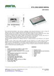
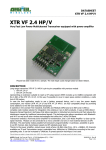
RTX-LONG-RANGE-869MHz
---------------------------------------------------------------------------------------------------------------------------------------------------
USER MANUAL
PRELIMINARY
RTX-LONG-RANGE-869MHz radio transceiver half-duplex, offers improved performance, as such as longer RF
range up to 3Km, operates in European band 869,4÷869,65MHz free licensed with no government taxes.
The high sensitivity level (-118dBm) joined with its typical ERP (+27dBm) can assure a budget-link around 145dB,
improving communication distance of 4-5 times better compared with traditional 10mW LPD devices.
It operates in 2 different modes: DIRECT MODE with modulation and demodulation of proper data protocol or
PACKET MODE, selectable via UART through AT commands, same as a radio-modem.
7 channels available, selectable depending on transmission speed. GFSK modulation.
Blocking immunity performance are compliant with Class 1, optimum rejection to the disturbances in the adjacent
channels.
In order to assure a battery power supply, the module has been designed for 3,3V supply, perfect for SCADA
application and its current consumption is around 600mA at maximum power emission, and 1 uA in stand-by mode.
Thanks to its tiny overall dimensions it can be fitted vertically on application circuit, with dimensions similar to the
Aurel standard receivers ( 38,1mm length x 24mm high x 4,5mm ), top layer is protected with metallic shield with the
purpose to obtain the European standard approvals.
Features
Double transmission mode: DIRECT AND PACKET
RS-232 signals store and forward operation
No coding or preamble demanded to User in PACKET
MODE
AT Commands for internal registers programming
HyperTerminal* compatible
Number of channels: 7 max
Overall dimension (38,1x24X4,5 mm)
UART Data Rate: 2400, 4800, 9600 bps
Max ERP: max 500 mW
High sensibility -118dBm with data-rate 500bps
Fixed Voltage supply 3,3V
Average range: 3 Km
Applications
Irrigation systems
Instruments and solar panel monitoring
Industrial control
Animal tracking
SCADA
Alarms
AMR
The technical features can change without forecasting. AUR°EL S.p.A doesn’t assume any responsibility of damage due to the improper use of the device.
------------------------------------------------------------------------------------------------------------------------------------------------------------------AUR°EL S.p.A. Via Foro dei Tigli, 4 - 47015 Modigliana (FC) – ITALY
Rev 3.3 08/11/2013
Page 1 of 17
Tel.: +39.0546.941124 Fax: +39.0546.941660
http://www.aurelwireless.com - email: [email protected]
RTX-LONG-RANGE-869MHz
---------------------------------------------------------------------------------------------------------------------------------------------------
USER MANUAL
PRELIMINARY
Absolute limits
Operating temperature
Storage temperature
Power supply
Input voltage
Output voltage
-20 °C ÷ +70 °C
-40 °C ÷ +100 °C
+3V
-1.0 ÷ Vcc + 0.3V
-1.0 ÷ Vcc + 0.3V
Technical features
DC Levels
Supply voltage pins 1,15.
Power consumption (rx mode)
Power consumption (tx mode @ +27 dBm)
Power consumption (stand-by mode)
Logic level “1” in input/output
Logic level “0” in input/output
RF TX
Frequency band
TX Power (direct mode Pin 14=1)
TX Power (direct mode Pin 14=0)
TX Power (packet mode)
Modulation type
Frequency deviation
Spurious < 1GHz
Spurious > 1GHz
Power on adjacent channel in TX ( see note2)
RF RX
Sensitivity, direct mode
IF Band
RF Band
Selectivity on adjacent channel (note3)
Saturation on adjacent channel (note4)
Blocking test ±2MHz (note5)
Blocking test ±10MHz (note5)
Performance
Serial Bit Rate 1
Outdoor range
Channels
Channelization
Switching times
PWRDN → RX
TX → RX
RX → TX
Default settings (only packet mode)
Channel
Min.
Tip.
Max.
Unità
2.7
3.3
32
500
8
3.6
550
10
Vcc
0.3xVcc
V
mA
mA
µA
V
V
29
23
29
MHz
dBm
dBm
dBm
-36
-30
50
KHz
dBm
dBm
nW
420
0.7xVcc
0
25
20
8
869,4÷869,65
27
21
GFSK
±3.5
-115
-116
12
600
50
≥87
85
85
2400
-120
90
94
4800
3000
9600
dBm
KHz
KHz
dB
dB
dB
dB
25
bps
m
n°
kHz
4
3,5
ms
ms
ms
(CN3) 869,5
MHz
7
TBD
The technical features can change without forecasting. AUR°EL S.p.A doesn’t assume any responsibility of damage due to the improper use of the device.
------------------------------------------------------------------------------------------------------------------------------------------------------------------AUR°EL S.p.A. Via Foro dei Tigli, 4 - 47015 Modigliana (FC) – ITALY
Rev 3.3 08/11/2013
Page 2 of 17
Tel.: +39.0546.941124 Fax: +39.0546.941660
http://www.aurelwireless.com - email: [email protected]
RTX-LONG-RANGE-869MHz
---------------------------------------------------------------------------------------------------------------------------------------------------
USER MANUAL
PRELIMINARY
Output power (tx)
Serial Data Rate
27
9600
dBm
Bps
Note l : As input serial signal is intended 8 bit ,not parity,1 stop bit .
Note 2: Test achieved with the method described in 7.6 section of the normative ETSI EN 300 220-1 V2.4.1
Note 3: Test achieved with the method described in 8.3 section of the normative ETSI EN 300 220-1 V2.4.1
Note 4: Test achieved with the method described in 8.3.4 section of the normative ETSI EN 300 220-1 V2.4.1
Note 5: Test achieved with the method described in 8.4 section of the normative ETSI EN 300 220-1 V2.4.1
PIN OUT
Pin-out
1)+V_PA_LNA
2)ANTENNA
3)GND
4)NC(No pin)
5)DM/UART
6)ENABLE
7)TX_RX / SP1
8) IN_DATA / SP2
9)OUT-DATA(RX direct mode)
10)GND
11)CN0 / RTS
12)CN1 / CTS
13)CN2 / TX_UART
14)PW_TX / RX_UART
15) +V_RD
Picture 2: pin-out of the module
N° Pin
1
Name
+V_PA_LNA
2
3
5
ANT
GND
DM / UART
Description
Front end power supply. Use a stable power source at 3,3V/1A. Connect a electrolytic capacitor
470-1000uF near GND PIN
Antenna connection, 50 ohm impedance
Connection to ground plane
I Digital input for choosing transmission mode.
Connected to 22÷47K pull-down
DM/UART
STATE
0
1
6
ENABLE
Direct-mode
Packet mode
Starting up Pin.
Connected to 22÷47K pull-down
PWRDN
0
1
STATE
Off
On
The technical features can change without forecasting. AUR°EL S.p.A doesn’t assume any responsibility of damage due to the improper use of the device.
------------------------------------------------------------------------------------------------------------------------------------------------------------------AUR°EL S.p.A. Via Foro dei Tigli, 4 - 47015 Modigliana (FC) – ITALY
Rev 3.3 08/11/2013
Page 3 of 17
Tel.: +39.0546.941124 Fax: +39.0546.941660
http://www.aurelwireless.com - email: [email protected]
RTX-LONG-RANGE-869MHz
---------------------------------------------------------------------------------------------------------------------------------------------------
USER MANUAL
PRELIMINARY
7
TX_RX / SP1
In DIRECT MODE (pin5 = 0), pin 7 = Input for TX/RX switching. Connected as follow:
TX/RX
0
1
X
STATE
RX
TX
RX
In PACKET MODE (pin5 = 1) , SP1 together with SP2 allow the selection of serial port speed UART
Functionality not available yet: the communication works only at
9600pbs, SP1 e SP2 not working
SP1
Pin7
0/X
0/X
1
1
8
IN_DATA / SP2
SP2
Pin8
0/X
1
1
1
UART Data Rate
bps
9600
19200
115200
Test mode
(non available)
Tab. SP1/SP2
In DIRECT MODE (pin5 = 0), pin 8 = Digital data input for DIRECT MODE transmission
Connect at 0 or 1 with data-rate 10÷3000Hz.
In PACKET MODE (pin5 = 1) , SP1 together with SP2 allows to select serial port speed UART
(pin 13,14).
For pin 8 settings (SP2) please see above pin 7 SP1 in PACKET
9
OUT-DATA
Digital data output in DIRECT MODE. This pin is active only in DIRECT MODE.
(RX direct mode)
10
GND
Connection to ground plane.
The technical features can change without forecasting. AUR°EL S.p.A doesn’t assume any responsibility of damage due to the improper use of the device.
------------------------------------------------------------------------------------------------------------------------------------------------------------------AUR°EL S.p.A. Via Foro dei Tigli, 4 - 47015 Modigliana (FC) – ITALY
Rev 3.3 08/11/2013
Page 4 of 17
Tel.: +39.0546.941124 Fax: +39.0546.941660
http://www.aurelwireless.com - email: [email protected]
RTX-LONG-RANGE-869MHz
---------------------------------------------------------------------------------------------------------------------------------------------------
USER MANUAL
PRELIMINARY
11
12
13
CN0 / RTS
CN1 / CTS
CN2 / TX_UART
In DIRECT MODE (pin5 = 0), pin 11(CN0), pin 12(CN1), pin13(CN2), allows to modify frequency
channel selection.
DIRECT-MODE pin5 = 0
RF Channel
Frequency
(MHz)
PIN11_CN0
PN12_CN1
PIN13_CN2
CN1
869,45
CN2
869,475
CN3
869,5
CN4
869,525
CN5
869,550
CN6
869,575
CN7
869,6
0/X
0/X
0/X
1
0/X
0/X
0/X
1
0/X
1
1
0/X
0/X
0/X
1
1
0/X
1
0/X
1
1
0 = GND, 1 = +Vcc, X = open
Note: Pins 11,12,13,14, when left open are internally connected to GND with 22K resistance.
In PACKET MODE (pin5=1), pin 11(RTS), pin12(CTS), pin13(TX_UART), pin14 (RX_UART), allow
the connection to a serial port for data Exchange and the programming of some registers through AT
commands
PIN
PIN11_RTS
PN12_CTS
PIN13_RX_UART
14
PW_TX /
RX_UART
Description
TBD
TBD
Serial data output in TTL RS-232 logic with 1 start bit (0V), 8 data bit and1
stop bit (3V). The line must be driven at high logic level (3V)
In direct mode (pin 5 = 0), the pin 14 allows to change the RF power transmission of approximately 6
dBm. This setting is useful when connected to external antenna and gain of 6-8dBm.
This setting allows you to return to the power limits shown in Table 5 by the normative
EN 300220-1 paragraph 7.2.3
PW_TX
(pin14)
1
0/X
STATO
RF output Power, max Power(+27dBm)
RF output Power (+21dBm)
In packet mode (pin5 = 1), pin 11 (RTS), pin12 (CTS), pin13 (TX_UART), pin14 (RX_UART), allow
connection to a serial port for data exchange and the programming of some internal registers using AT
commands.
PIN
PIN14_RX_UART
15
+V_RD
Description
Serial data output in TTL RS-232 logic with start bit 1 (0V), 8 data bits and
1 stop bit (3V). The line must be driven to a high logic level (3V).
Radio digital circuit power supply. Use a stable power source at 3,3V/100mA. Connect a electrolytic
capacitor 10-100uF near GND PIN.
Tab. 1: PIN description
The technical features can change without forecasting. AUR°EL S.p.A doesn’t assume any responsibility of damage due to the improper use of the device.
------------------------------------------------------------------------------------------------------------------------------------------------------------------AUR°EL S.p.A. Via Foro dei Tigli, 4 - 47015 Modigliana (FC) – ITALY
Rev 3.3 08/11/2013
Page 5 of 17
Tel.: +39.0546.941124 Fax: +39.0546.941660
http://www.aurelwireless.com - email: [email protected]
RTX-LONG-RANGE-869MHz
---------------------------------------------------------------------------------------------------------------------------------------------------
USER MANUAL
PRELIMINARY
Operating mode
The device’s operating modes can be summarized in 5 conditions
1. Test Mode
2. DIRECT MODE
3. PACKET MODE
4. Power Down Mode
5. Command Mode
1. Test Mode
The Test Mode can be reached by short circuiting SP1 and SP2 pins to +V, before of the switching of the
device. This condition it is not available yet.
2. DIRECT MODE (pin 5 =0)
This mode is used to transfer proprietary data packets via RF, without the module prepares the data for the
transmission.
In this way the packet must include a preamble long enough and a coding (example Manchester) in order to
balance the average Voltage value. Single data duration must be included in time interval between 20mS and
350mS (high+low).
Transmission
Direct mode transmission is activated bringing pin 7 high (TX_RX). Data on pin 8 (IN_DATA) will sent via
radio.
Receiving
Same as the transmission. It is activated bringing pin 7 low (TX_RX).
Received data will available on pin 9.
3. PACKET MODE (pin5 = 1)
When a start bit (low logic level , 0V) is present on input line RX_UART (pin14) and consequently at least
one data Byte, the device enters in transmission mode.
Store&forward system could be described in sequence:
The technical features can change without forecasting. AUR°EL S.p.A doesn’t assume any responsibility of damage due to the improper use of the device.
------------------------------------------------------------------------------------------------------------------------------------------------------------------AUR°EL S.p.A. Via Foro dei Tigli, 4 - 47015 Modigliana (FC) – ITALY
Rev 3.3 08/11/2013
Page 6 of 17
Tel.: +39.0546.941124 Fax: +39.0546.941660
http://www.aurelwireless.com - email: [email protected]
RTX-LONG-RANGE-869MHz
---------------------------------------------------------------------------------------------------------------------------------------------------
USER MANUAL
PRELIMINARY
Serial reception unit A / Transmission RF unit A
RF reception unit B / Transmission serial unit B [Picture. 3]
The absence of the data input in Pin 14 is established from an Timeout expiring (Fixed by the serial data
rate). Then the transceiver will not memorize further data input until the effective RF transmission of the
data in the internal buffer is occurred.
The data are transmitted on RF channel only after the serial Rx is expired.
Likewise the receiver part will analyze the incoming RF packet going on with the serial transmission in case
of valid data, deleting in case of wrong data.
Unit A serial reception
Unit A serial STORE
Unit A
RF FORWARD
Unit A RF transmission
Radiofrequency
Valid packet from unit B and
transmitted through serial
Unit B RF reception
Unit B
RF STORE
Unit B
serial FORWARD
Unit B serial transmission
0
t [ms]
Picture. 3: store&forward mechanism
As shown by the Pic. 3 time diagram, the time interval, from the starting moment (instant 0) when the data
reaches the module’s port, to the moment when it is received by the remote module, depends on the number
of Bytes that form the packet and also on the serial speeds used for the reception as well as for the
transmission.
For the correct operation of the device consider that it’s not allowed to have contemporary phases
inside the same unit.
For instance : If A unit is in RF transmission phase, eventual incoming data will not memorized in the
buffer.
Fig. 4 shows the case of the transmission of two packets in a sequence from unit A to unit B: packet #1
enters in unit A and it’s transmitted to unit B that forwards it through the serial port. The transmission of the
packet #2 must be carried out, keeping in mind that the end of the serial reception of unit A has to take place
AFTER the end of the serial transmission of packet #1 by unit B so to avoid the overlapping of the RF
reception and of the serial transmission phases in this device: it is therefore necessary to enter a safety
interval between the transmissions of the two packets in function of the number of byte of the first packet, of
The technical features can change without forecasting. AUR°EL S.p.A doesn’t assume any responsibility of damage due to the improper use of the device.
------------------------------------------------------------------------------------------------------------------------------------------------------------------AUR°EL S.p.A. Via Foro dei Tigli, 4 - 47015 Modigliana (FC) – ITALY
Rev 3.3 08/11/2013
Page 7 of 17
Tel.: +39.0546.941124 Fax: +39.0546.941660
http://www.aurelwireless.com - email: [email protected]
RTX-LONG-RANGE-869MHz
---------------------------------------------------------------------------------------------------------------------------------------------------
USER MANUAL
PRELIMINARY
the serial speed of unit B and in function of the time required TRF [ms ] for the transmission of the packet on
the RF which depends upon the number of bytes of the packet and it is given by
TRF [ms ] = K + ???⋅ N byte
with K= TBD @9600bps, K=TBD @4800bps, K=TBD @2400bps.
The last byte of the second packet must enter unit A after unit B has ended the serial
transmission of the first packet .
Serial packet reception #1 unit A
The #2 packet does not enter in A unit
during the RF transmission of #1 packet
Serial packet reception #2 unit A
Not possible to send
data
Packet #1 RF transmission, A Unit
Packet #1 RF transmission, B Unit
t [ms]
0
Picture. 4: Two data packets transmission
4. Power Down Mode
By bringing to a low level or left open PIN 6 (ENABLE) device enters into a power saving state, the
consumption in fact is limited to less than 5 µA. In this mode, the transceiver can neither receive nor
transmit. It is necessary to commutate pin 6 in high level (+3V) to bring it back to the normal operating state.
NOTE:
At the first feeding cycle, you should enable the Enable pin high after the power supply is stable, bring it
back down to enter the Power-down mode.
This action is required to ensure the reported consumption in a specific phase in the power-down.
5. Command Mode (Programmation of the module)
The technical features can change without forecasting. AUR°EL S.p.A doesn’t assume any responsibility of damage due to the improper use of the device.
------------------------------------------------------------------------------------------------------------------------------------------------------------------AUR°EL S.p.A. Via Foro dei Tigli, 4 - 47015 Modigliana (FC) – ITALY
Rev 3.3 08/11/2013
Page 8 of 17
Tel.: +39.0546.941124 Fax: +39.0546.941660
http://www.aurelwireless.com - email: [email protected]
RTX-LONG-RANGE-869MHz
---------------------------------------------------------------------------------------------------------------------------------------------------
USER MANUAL
PRELIMINARY
The Command Mode state allows the Owner to configure the operating parameters of the device. The
programming is carried out by means of ‘AT’ type commands sent to the TX_UART (pin 13) at the speed set
by means of pins SP1 and SP2 (pin 7 and pin 8). The module’s answers shall be given on the RX_UART
(pin 14).
To enter in Command Mode from PACKET MODE, it is necessary to send on the TX_UART (pin 13) a
sequence of 3 consecutive ASCII characters ‘+’, i.e.: (+++). A module under Command Mode state is unable
to the RF reception and transmission
At this purpose, we recommend using the RS232 port or USB port of a PC, physically interfaced to the radio
module to get logic levels 0-3V, connect the RX and TX signals leaving disconnected RTS and CTS (nonimplemented). Use a program to communicate with the serial port, Hyperteminal, RealTerm or other similar,
setting the following parameters:
communication speed established by SP1 and SP2 (9600, 19200, 115200), a START bit, 8 data bits, and a
STOP bit, no parity, select CR and LF.
Try sending from PC + + + , if you will get OK then the communication is correct.
Type ATCC, you will get good response in confirming the exit from Command Mode.
.
Available Registers and Commands
The commands that can be sent to the module regard the reading and writing of the registers containing the
operation setting of the device.
The reading and writing of the configuration registers and the sending of the commands to the module are
carried out by entering the ’AT’ sequence ( Standards used in PSTN modem) before the command’s or
register’s name.
Below is listed the available commands, for their usage follows the writing and reading examples of the
registers:
AT
Upper case characters that always
proceed a command or register
COMMAND
The commands are codes that contain one or
more characters.
<CR>
The command always end with <CR>
Carriage Return
Register
Name
CHANNEL
Function
Working radio channel
Values
0 = 869,45MHz
1 = 869,475MHz
2 = 869,5MHz (default)
3 = 869,525MHz
4 = 869,55MHz
5 = 869,575MHz
6 = 869,6MHz
R/W
S2
S3
POWER
Output RF power
0=
1=
2=
3=
4=
R/W
+8 dBm
+16dBm
+22dBm
+25dBm
+27dBm (default)
R/W
The technical features can change without forecasting. AUR°EL S.p.A doesn’t assume any responsibility of damage due to the improper use of the device.
------------------------------------------------------------------------------------------------------------------------------------------------------------------AUR°EL S.p.A. Via Foro dei Tigli, 4 - 47015 Modigliana (FC) – ITALY
Rev 3.3 08/11/2013
Page 9 of 17
Tel.: +39.0546.941124 Fax: +39.0546.941660
http://www.aurelwireless.com - email: [email protected]
RTX-LONG-RANGE-869MHz
---------------------------------------------------------------------------------------------------------------------------------------------------
USER MANUAL
PRELIMINARY
S8
RADIO_SPEED
S9
TEST_MODE
S15
VERSION
Command
Name
WR
WRITE
CC
COMMAND
CLOSE
0= 600bps
1= 1200bps (default)
2= 2400bps
3= 9600bps
TBD
Firmware version
R/W
TBD
Variable
R
Function
Writing of the value in EEPROM registers
Output from Command Mode
Tab. 2: commands
Answers to the commands and to the operation on registers:
Positive answer:
OK<CR><LF>
Negative answer:
<bl> ERROR<CR><LF>
Forbidden operation:
<bl> NO ACCESS<CR><LF>
With <CR> Carriage Return, ASCII 13 character; <LF> Line Feed, ASCII 10 character; <bl> ASCII 32 character.
Reading of a Register:
Syntax:
ATSx<CR><LF>
[x = 1, ...,16 Register to be read]
Answer :
the value contained in the register if the command has been given correctly .
It’s followed by <CR> <LF>.
The value of registers is returned digit by digit in ASCII value.
Example: ‘16’ is the series of ASCII 0x31,0x36 codes, corresponding to ‘1’ e ‘6’ digits.
It must follow this procedure of interpretation even in the case of writing the value of a register.
Writing of a register:
Syntax:
ATSx=Y<CR><LF>
[x = 2, 3, 4 register to write,
y = value to insert]
The technical features can change without forecasting. AUR°EL S.p.A doesn’t assume any responsibility of damage due to the improper use of the device.
------------------------------------------------------------------------------------------------------------------------------------------------------------------AUR°EL S.p.A. Via Foro dei Tigli, 4 - 47015 Modigliana (FC) – ITALY
Rev 3.3 08/11/2013
Page 10 of 17
Tel.: +39.0546.941124 Fax: +39.0546.941660
http://www.aurelwireless.com - email: [email protected]
RTX-LONG-RANGE-869MHz
---------------------------------------------------------------------------------------------------------------------------------------------------
USER MANUAL
PRELIMINARY
Answer :
as described : ‘Risposte ai comandi’ (Answer to the commands)
All programmed values in the registers cause a change in the operating conditions of the module that will be
lost when it’s powered off, unless they have been stored in the EEPROM of the microcontroller with the
appropriate command ATWR: in this case the changed values will be active also the next switching-on.
Command for saving the value of the registers in EEPROM
Syntax:
Answer :
ATWR<CR><LF>
as described : ‘Risposte ai comandi’
(Answer to the commands)
Comando di uscita da Command Mode
Syntax:
Answer :
ATCC<CR><LF>
as described : ‘Risposte ai comandi’
(Answer to the commands)
The escape from Command Mode, in absence of ATCC command, occurs automatically after 5 seconds of
inactivity.
DIRECT-MODE schema:
The Direct Mode allows the transmission and reception of digital data from proprietary protocols.
The transmission is activated by carrying high the pin 7 (TX / RX) and entering the data directly on the
connector J8 (TX), similarly the received data are available on the J9 connector (RX) with pin (TX / RX) is
kept low.
The data must have a length in between 20ms and 350ms (defined as the length of single bit high + low).
However in order to avoid problems in the reconstruction of the signals to the demodulator, we recommend
the implementation of a protocol containing a preamble and data coded with Manchester or Miller or other
similar techniques.
The modulation of pin8 with data from UART is not recommended. The dip-switches 1-3 of S2 select the
radio channel or during the RX phase or after to the exchange RX → TX or POWER_DOWN → TX, during
the TX phase they are disabled. The dip 4 of S2 decrease the power by 6 dBm for the purpose of the
homologation of the transmitting part, in applications where you need an external antenna with a gain of 68dBm.
The technical features can change without forecasting. AUR°EL S.p.A doesn’t assume any responsibility of damage due to the improper use of the device.
------------------------------------------------------------------------------------------------------------------------------------------------------------------AUR°EL S.p.A. Via Foro dei Tigli, 4 - 47015 Modigliana (FC) – ITALY
Rev 3.3 08/11/2013
Page 11 of 17
Tel.: +39.0546.941124 Fax: +39.0546.941660
http://www.aurelwireless.com - email: [email protected]
RTX-LONG-RANGE-869MHz
---------------------------------------------------------------------------------------------------------------------------------------------------
USER MANUAL
PRELIMINARY
Picture 4: Direct-Mode electrical schematic
PACKET-MODE schema:
The connection of the module for the operation in packet-mode is extremely simple.
The technical features can change without forecasting. AUR°EL S.p.A doesn’t assume any responsibility of damage due to the improper use of the device.
------------------------------------------------------------------------------------------------------------------------------------------------------------------AUR°EL S.p.A. Via Foro dei Tigli, 4 - 47015 Modigliana (FC) – ITALY
Rev 3.3 08/11/2013
Page 12 of 17
Tel.: +39.0546.941124 Fax: +39.0546.941660
http://www.aurelwireless.com - email: [email protected]
RTX-LONG-RANGE-869MHz
---------------------------------------------------------------------------------------------------------------------------------------------------
USER MANUAL
PRELIMINARY
The dip-switch S1 selects the speed of the UART interface, the transmission and reception signals, and the
settings of the radio module are obtained through the communication input asynchronous serial interface
output.
The controls for the serial CTS and RTS are not implemented yet and therefore together with pin9 (out-date
DM) will not be connected.
The module always operates in receive mode, the switching from reception to transmit part is automatically
activated when the first byte of data enters the hall 14 (RX_UART).
Picture 5: Packet-Mode Electrical schema
The technical features can change without forecasting. AUR°EL S.p.A doesn’t assume any responsibility of damage due to the improper use of the device.
------------------------------------------------------------------------------------------------------------------------------------------------------------------AUR°EL S.p.A. Via Foro dei Tigli, 4 - 47015 Modigliana (FC) – ITALY
Rev 3.3 08/11/2013
Page 13 of 17
Tel.: +39.0546.941124 Fax: +39.0546.941660
http://www.aurelwireless.com - email: [email protected]
RTX-LONG-RANGE-869MHz
---------------------------------------------------------------------------------------------------------------------------------------------------
USER MANUAL
PRELIMINARY
Power supply:
The transceiver in the transmission phase can absorb current peaks of up to 600mA. It’s necessary to use a
power supply system that maintains stable and clean voltage supply in the fast transient current. In case it’s
requested to use a voltage regulator it’s recommended the choice of models with characteristic of "fast
transient response", following it’s suggested a schema tested by Aurel suitable for the module RTX-LONGRANGE.
Picture 6: Fixed power supply 3V-1A DC-DC
Device usage
In order to obtain the performances described in the technical specifications and to comply with the
operating conditions which characterize the Certification, the transmitter should be mounted on a printed
circuit taking into account the following:
Voltage Supply:
1. The transmitter must be supplied from very low voltage safety source protected against the printed
circuits. Maximum voltage variations allowed: 2.1 ÷ 3.6 V.
The technical features can change without forecasting. AUR°EL S.p.A doesn’t assume any responsibility of damage due to the improper use of the device.
------------------------------------------------------------------------------------------------------------------------------------------------------------------AUR°EL S.p.A. Via Foro dei Tigli, 4 - 47015 Modigliana (FC) – ITALY
Rev 3.3 08/11/2013
Page 14 of 17
Tel.: +39.0546.941124 Fax: +39.0546.941660
http://www.aurelwireless.com - email: [email protected]
RTX-LONG-RANGE-869MHz
---------------------------------------------------------------------------------------------------------------------------------------------------
USER MANUAL
PRELIMINARY
However it is preferable to maintain a stable voltage to a predetermined value in the range of voltage as
specified above, using a voltage regulator "Fast transient response" (see paragraph power supply).
2. Decoupling, next to the transmitter, with a ceramic capacitor of minimum 100.000 pF.
3. Connect electrolytic capacitor 220uF-470uF, low ESR, close to the pin 1 (+ V_PA / LNA).
Pin interface:
Put a capacity of 22-100pF close to the corresponding pins of signal connection, connected between them
and the ground plane.
The capacitance value varies according to the pin of the module, so please follow to the electrical schematic
of Figure 4 and 5 and the lay-out of figure 6.
Ground:
The mass must surround at the best the welding area of the transmitter and must also be realized in the lower
face in order to obtain the optimal result, with the through holes connecting the two ground planes.
Antenna:
Connect pin 2 (antenna) to the coaxial connector or antenna, with microstrip constant impedance of 50R,
width 3.2 mm for PCB with thickness 1.6 mm and 1.6 mm for PCB with thickness 1mm. (see Figure 6)
The antenna is a typical rigid copper wire (insulated or not) of 8cm length and cross-section of 0.5 mm ²
placed vertically to the ground plane.
Other placements of antenna (bend, spiral) will work but performance are not predictable.
As an alternative to connect the module to an external antenna, connect an SMA connector into PCB using
microstrip 50 (see figure below).
The proposed lay-out below, for example, shows the connections of signals and power supply on the top and
a ground plane on the bottom side of the extended PCB that surrounds the radio module. The cross-link
antenna impedance 50R is 3.2 mm wide, specifically, calculated for double-sided epoxy glass 1.6 mm thick.
The pin 1 of the power supply, connect the power supply with wide track and 2mm electrolytic capacitor
220uF restaurant nearby.
The pins of the input signals and output of the module are connected to the capacity from 22 to 100pF places
in the vicinity of the same.
The technical features can change without forecasting. AUR°EL S.p.A doesn’t assume any responsibility of damage due to the improper use of the device.
------------------------------------------------------------------------------------------------------------------------------------------------------------------AUR°EL S.p.A. Via Foro dei Tigli, 4 - 47015 Modigliana (FC) – ITALY
Rev 3.3 08/11/2013
Page 15 of 17
Tel.: +39.0546.941124 Fax: +39.0546.941660
http://www.aurelwireless.com - email: [email protected]
RTX-LONG-RANGE-869MHz
---------------------------------------------------------------------------------------------------------------------------------------------------
USER MANUAL
PRELIMINARY
Picture 7: Example of lay-out, the connection tracks on PCB on the top side and ground plane in the button
side.
Normative
The RTX_LONG-RANGE-869MHZ transceiver is compliant with the European normative EN 300 220
V2.4.1 (2012-05), ed EN 301 489-3 V1.5.1 (2012-07).
Tests have been carried out through transmissions of Pseudo Code Random at 500 bps(CEPT 70-03)..
The occupancy of bandwidth is verified been carried out through transmissions of Pseudo Code Random at
500 bps.
In addition, the product has been tested according to EN 60950 and it can be utilized inside a
special insulated housing that assures the compliance with the above mentioned rule. The
transceiver must be operated from a very low voltage source, safety protected against short circuits.
The usage of the transceiver is foreseen inside housings that assure the overcoming of the rule EN
61000-4-2 not directly applicable to the module itself. In particular, it is the user's care the
insulation of the external antenna connection and antenna itself since the RF output of the receiver
is not able to directly bear the electrostatic charges foreseen by the above mentioned rule.
CEPT 70-03 Recommendation
The RTX_LONG-RANGE-869MHz transceiver operates in a harmonized frequency band and therefore, in
order to comply with local regulations, the device must be used on the time scale with maximum duty-cycle
time 10% (equivalent to 6 to 60 minutes of usage ).
The technical features can change without forecasting. AUR°EL S.p.A doesn’t assume any responsibility of damage due to the improper use of the device.
------------------------------------------------------------------------------------------------------------------------------------------------------------------AUR°EL S.p.A. Via Foro dei Tigli, 4 - 47015 Modigliana (FC) – ITALY
Rev 3.3 08/11/2013
Page 16 of 17
Tel.: +39.0546.941124 Fax: +39.0546.941660
http://www.aurelwireless.com - email: [email protected]
RTX-LONG-RANGE-869MHz
---------------------------------------------------------------------------------------------------------------------------------------------------
USER MANUAL
PRELIMINARY
The technical features can change without forecasting. AUR°EL S.p.A doesn’t assume any responsibility of damage due to the improper use of the device.
------------------------------------------------------------------------------------------------------------------------------------------------------------------AUR°EL S.p.A. Via Foro dei Tigli, 4 - 47015 Modigliana (FC) – ITALY
Rev 3.3 08/11/2013
Page 17 of 17
Tel.: +39.0546.941124 Fax: +39.0546.941660
http://www.aurelwireless.com - email: [email protected]