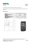
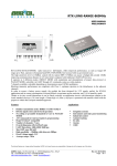
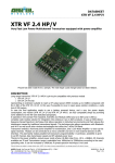
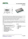
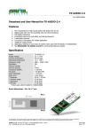
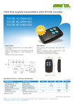
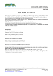
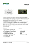
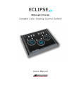
1
CLIENT SOFTWARE INSTRUCTION
MANUAL AUREL DEMO ZIGBEE
---------------------------------------------------------------------------------------------------------------------------------------------------
User Guide
Client Software instruction manual for Aurel Demo ZigBee
The ZigBee Aurel network configuration, at least at the beginning, needs to have the coordinator
connected to the PC or to another high counting performance instrument, able to release a graphics
interface.
We consider appropriate pick up information on the devices linked to the network and about their
status (ON/OFF), and keep them easily visible in a graphic way.
Thus is provided a Demo software, to be installed on the PC, that permit the coordinator interfacing
The Demo goal is to demonstrate how is possible create a ZigBee network, supervising it through a
steady check up of its devices features, and sending to the remote nodes several commands to using
their available I/O for messages exchanging.
Demo must be consider an useful instrument in order to verify the ZigBee Aurel networks
capability, even through the RF covering, and a starting point for a software development to a
targeted application.
Besides to the graphics panels there is a LOG window where all the commands delivered by serial
and their responses are getting showed.
That window must be regarded as an auxiliary tool for the developer, in way of learning the
commands sending at coordinator start-up and network configuration time, and in way of learning
which are the commands granted for a network diagnostic.
Here below it comes described how to install and use the Client Software provided by AUREL for a
ZigBee network monitoring.
Really it is provided an OCX that should be installed through its setup file. OCX must be installed
before installing the Client software because it form a part of the latter.
Developer can therefore, as interface toward the coordinator, use the OCX including it as a
component into own project. In this way can obtain a greater abstraction level compared with the
one provided by the commands directly reserved to the device.
For more information concerning the OCX using, please see the OCX User manual
Information subject to change without notice. AUREL S.p.A makes no warranty and assumes no liability in connection with any use of this information
--------------------------------------------------------------------------------------------------------------------------------------------------------------------AUREL S.p.A. Via Foro dei Tigli, 4 - 47015 Modigliana (FC) – ITALY
04/04/2008 - Rev.A
Pag 1 di 20
Tel.: +39.0546.941124 Fax: +39.0546.941660
http://www.aurelwireless.com - email: [email protected]
CLIENT SOFTWARE INSTRUCTION
MANUAL AUREL DEMO ZIGBEE
---------------------------------------------------------------------------------------------------------------------------------------------------
User Guide
OCX installation
In order to install the OCX please follow the instruction stated below:
1. Decompress the file OCX.rar provided
2. Launch the file exe called Setup.exe
3. The following graphics panel will appear:
4. To proceed the installation click on “OK”
5. The following graphics panel will appear:
Information subject to change without notice. AUREL S.p.A makes no warranty and assumes no liability in connection with any use of this information
--------------------------------------------------------------------------------------------------------------------------------------------------------------------AUREL S.p.A. Via Foro dei Tigli, 4 - 47015 Modigliana (FC) – ITALY
04/04/2008 - Rev.A
Pag 2 di 20
Tel.: +39.0546.941124 Fax: +39.0546.941660
http://www.aurelwireless.com - email: [email protected]
CLIENT SOFTWARE INSTRUCTION
MANUAL AUREL DEMO ZIGBEE
---------------------------------------------------------------------------------------------------------------------------------------------------
User Guide
6. Choose the installation directory of the OCX and click on the button.
7. The installation will be completed.
Information subject to change without notice. AUREL S.p.A makes no warranty and assumes no liability in connection with any use of this information
--------------------------------------------------------------------------------------------------------------------------------------------------------------------AUREL S.p.A. Via Foro dei Tigli, 4 - 47015 Modigliana (FC) – ITALY
04/04/2008 - Rev.A
Pag 3 di 20
Tel.: +39.0546.941124 Fax: +39.0546.941660
http://www.aurelwireless.com - email: [email protected]
CLIENT SOFTWARE INSTRUCTION
MANUAL AUREL DEMO ZIGBEE
---------------------------------------------------------------------------------------------------------------------------------------------------
User Guide
Client Sotware Demo AUREL installation
In order to install the Client please follow the instruction stated below:
1. Decompress the file Client.rar provided
2. Launch the file exe. called Setup.exe
3. The following graphics panel will appear:
4. To proceed the installation click on “OK”
5. The following graphics panel will appear:
Information subject to change without notice. AUREL S.p.A makes no warranty and assumes no liability in connection with any use of this information
--------------------------------------------------------------------------------------------------------------------------------------------------------------------AUREL S.p.A. Via Foro dei Tigli, 4 - 47015 Modigliana (FC) – ITALY
04/04/2008 - Rev.A
Pag 4 di 20
Tel.: +39.0546.941124 Fax: +39.0546.941660
http://www.aurelwireless.com - email: [email protected]
CLIENT SOFTWARE INSTRUCTION
MANUAL AUREL DEMO ZIGBEE
---------------------------------------------------------------------------------------------------------------------------------------------------
User Guide
6. Choose the installation directory of the client and click on the button.
7. The following graphics panel will appear:
Information subject to change without notice. AUREL S.p.A makes no warranty and assumes no liability in connection with any use of this information
--------------------------------------------------------------------------------------------------------------------------------------------------------------------AUREL S.p.A. Via Foro dei Tigli, 4 - 47015 Modigliana (FC) – ITALY
04/04/2008 - Rev.A
Pag 5 di 20
Tel.: +39.0546.941124 Fax: +39.0546.941660
http://www.aurelwireless.com - email: [email protected]
CLIENT SOFTWARE INSTRUCTION
MANUAL AUREL DEMO ZIGBEE
---------------------------------------------------------------------------------------------------------------------------------------------------
User Guide
8. Insert the programs group where you prefer view the client software, and click on the
button.
9. The installation will be completed.
Information subject to change without notice. AUREL S.p.A makes no warranty and assumes no liability in connection with any use of this information
--------------------------------------------------------------------------------------------------------------------------------------------------------------------AUREL S.p.A. Via Foro dei Tigli, 4 - 47015 Modigliana (FC) – ITALY
04/04/2008 - Rev.A
Pag 6 di 20
Tel.: +39.0546.941124 Fax: +39.0546.941660
http://www.aurelwireless.com - email: [email protected]
CLIENT SOFTWARE INSTRUCTION
MANUAL AUREL DEMO ZIGBEE
---------------------------------------------------------------------------------------------------------------------------------------------------
User Guide
Client software employment
Further is described how to use the Client Software Demo AUREL:
Insert into the Demo Board the module with the component side oriented toward the outside
Afterwards the module USB drivers installation, please connect the Demo Board to the PC through
a USB cable.
The newly connected hardware will be automatically recognized.
The Red led ON into the Demo Board mean power supply steady
Through the PC is possible check which is the new COM port that has been created:
Control panel – System – Hardware - Peripheral control – Port (COM and LPT)
Now launch Client_Program.exe
The following graphics panel will appear:
Insert Serial Port number and click on OK button.
Now, the Demo Software performs an automatic coordinator researching to the declared serial port,
through the commands sending and a response waiting.
The following graphics panel will appear:
Information subject to change without notice. AUREL S.p.A makes no warranty and assumes no liability in connection with any use of this information
--------------------------------------------------------------------------------------------------------------------------------------------------------------------AUREL S.p.A. Via Foro dei Tigli, 4 - 47015 Modigliana (FC) – ITALY
04/04/2008 - Rev.A
Pag 7 di 20
Tel.: +39.0546.941124 Fax: +39.0546.941660
http://www.aurelwireless.com - email: [email protected]
CLIENT SOFTWARE INSTRUCTION
MANUAL AUREL DEMO ZIGBEE
---------------------------------------------------------------------------------------------------------------------------------------------------
User Guide
In case the coordinator has not been properly connected to the serial port, no one response will be
received to the sent commands. After 10 attempts client software will shut down automatically
In case the coordinator has been properly connected, it creates a network and all the information
will be displayed into the appropriate fields of the main graphics panel (see the picture here above).
Information subject to change without notice. AUREL S.p.A makes no warranty and assumes no liability in connection with any use of this information
--------------------------------------------------------------------------------------------------------------------------------------------------------------------AUREL S.p.A. Via Foro dei Tigli, 4 - 47015 Modigliana (FC) – ITALY
04/04/2008 - Rev.A
Pag 8 di 20
Tel.: +39.0546.941124 Fax: +39.0546.941660
http://www.aurelwireless.com - email: [email protected]
CLIENT SOFTWARE INSTRUCTION
MANUAL AUREL DEMO ZIGBEE
---------------------------------------------------------------------------------------------------------------------------------------------------
User Guide
Information concerning the coordinator and the network created are the following:
1. MAC address of the coordinator
2. Channel were the network was established (Coordinator will run an auto scan on all the
available channels, and the network will create on the most free of noise
3. PAN ID: Network identification (default value on coordinator is equal to Less Significant 14
bits of its MAC)
4. Network status: locked - unlocked (see “Command user Manual for Aurel XTR-ZB1
Modules”).It is displayed into the lower left window below.
Into the main graphics panel are displayed, as a list, all the devices joined to the net as per the
following picture:
Information subject to change without notice. AUREL S.p.A makes no warranty and assumes no liability in connection with any use of this information
--------------------------------------------------------------------------------------------------------------------------------------------------------------------AUREL S.p.A. Via Foro dei Tigli, 4 - 47015 Modigliana (FC) – ITALY
04/04/2008 - Rev.A
Pag 9 di 20
Tel.: +39.0546.941124 Fax: +39.0546.941660
http://www.aurelwireless.com - email: [email protected]
CLIENT SOFTWARE INSTRUCTION
MANUAL AUREL DEMO ZIGBEE
---------------------------------------------------------------------------------------------------------------------------------------------------
User Guide
In case more then 12 devices will be joined, use the pushbutton UP and DOWN to scroll the list.
Each device has to report the following instruction:
1. Device number
2. Device MAC Address 64 bit
3. Keep Alive Status (see “Command user Manual for Aurel XTR-ZB1 Modules”) that could be
set from every single window device’s (described here below): ZERO mean keep alive disabled,
ONE mean keep alive enabled
4. Device short address
5. Device Name: It is possible point out a name to identify the device through its window. By
logic level will be made a name-MAC address linking, while the short address is changeable.
6. Device type: Router or end device.
7. Device Status:
• ON = Green LED lighting
• OFF = Red LED lighting
Launching the program, devices status will be OFF. It switching ON in case of a response detecting
to the cyclical ping command, enforceable through the pushbutton (described here below), or
getting into the device handling window (described here below).
Into the main page is further present a LOG window where are displayed all the sent-received
messages through from the software package to the serial line.
Using TX, being displayed commands sent from the PC towards XTR-ZB1 module, and with RX
them from modules to the software package
Software package besides, Saves two files into the installation folder.
1. INI File, named as the MAC address of coordinator holds the information related to the net and
to the joined device
2. TXT File, holds the MAC address of the devices joined to the net.
These two Files are created automatically by the program and transformed by itself in accordance
with network modifications.
Information subject to change without notice. AUREL S.p.A makes no warranty and assumes no liability in connection with any use of this information
--------------------------------------------------------------------------------------------------------------------------------------------------------------------AUREL S.p.A. Via Foro dei Tigli, 4 - 47015 Modigliana (FC) – ITALY
04/04/2008 - Rev.A
Pag 10 di 20
Tel.: +39.0546.941124 Fax: +39.0546.941660
http://www.aurelwireless.com - email: [email protected]
CLIENT SOFTWARE INSTRUCTION
MANUAL AUREL DEMO ZIGBEE
---------------------------------------------------------------------------------------------------------------------------------------------------
User Guide
At any program’s launching being charged all the information to the net, by these two Files. In this
way, every single time the program will be launched, the network information located at the
previous closing are maintained
Pushbuttons meaning and how to use them
Here below is reported what is meaning the pushing of the pushbuttons and the consequent using.
1. LOCK/UNLOCK NET: It sends the command of lock-unlock of the net. (see “Command user
Manual for Aurel XTR-ZB1 Modules”). Net status is reported into the left lower main screen
side
2. SAVE DATA: It saves into the Files INI and TXT previous described , all the information
related to the net status . This saving could be performed during the program closing.
3. ADD DEVICE: It sends to the coordinator the command granted to the linking of a device
having a MAC address same as the ones keyed in. NOTE: If the device doesn’t links the net,
nothing will be saved into the INI and TXT files. New MAC saving into these files, happens
pushing SAVE DATA button, or closing the application, just in case the device having this
MAC, will really linked to the network.
4. CHANGE CHANNEL: It sends to the coordinator the command granted for channel changing.
Entering the new channel number (from 11 to 26). Pressing 0 or 27 will run a complete scan to
all the available channels, and chosen the most free of noise If will be pressed a number not
included in this range, the application will doesn't work.
5. DELETE DEVICE: Permit to delete a device listed into the main graphics panel. write the
device number chosen to be deleted and press OK. It is required the confirmation for MAC
chosen to be deleted, but there is no automatic saving into INI and TXT files. Saving will
performed only after pressing the button SAVE DATA, or at the program closing. NOTE: In
point of fact even pushing the SAVE DATA button, the device deleting will be performed only
by the application level while no one commands will forwarded to the coordinator in order to
erase from its schedule the desired device. To advise the removal even to the coordinator, it is
necessary close the application and switch off the device. Switching on the coordinator and relaunching again the application, will be launched a schedule update.
Information subject to change without notice. AUREL S.p.A makes no warranty and assumes no liability in connection with any use of this information
--------------------------------------------------------------------------------------------------------------------------------------------------------------------AUREL S.p.A. Via Foro dei Tigli, 4 - 47015 Modigliana (FC) – ITALY
04/04/2008 - Rev.A
Pag 11 di 20
Tel.: +39.0546.941124 Fax: +39.0546.941660
http://www.aurelwireless.com - email: [email protected]
CLIENT SOFTWARE INSTRUCTION
MANUAL AUREL DEMO ZIGBEE
---------------------------------------------------------------------------------------------------------------------------------------------------
User Guide
6. RESET: sends the command reset to the device. After a coordinator reset, application will send
the commands containing all the linkable MAC addresses (loaded by TXT file) and lock net
command. Please note as into the main screenshot, the devices short addresses are erased
following the reset operation. That is given by the coordinator that after the reset, it erase all the
network information, thus even the linked devices short addresses. It is possible obtain a
different short address to the next association. NOTE: If a coordinator reset will performed, in
order to obtain a communication between it and the others network devices, it is necessary
perform at least an Half Reset to the remote devices. Above-mentioned Reset will performed in
automatic if the remote devices has the keep alive option enabled, whereas must be done in
manual mode in contrary case.
7. ENABLE CYCLING PING: Enables the sending of PING COMMAND CYCLING towards
Routers belonging the list. It comes required the time between a PING command and the next
one. The above-mentioned time is limited within the lower treshold to 200ms. If a lower value
will press wrongly, the application will set it automatically to 200ms. In case the PING
command get an answer from remote router, led placed alongside of the interrogated device
becomes green. In case of missing answer the led becomes red. PLEASE NOTE: PING
command can’t be forwarded to the End devices, because the End devices utilize at most a Poll
Rate time to answer. This forces a very sensible slowdown of the PING frequency towards the
other devices. The led placed alongside the End devices becomes yellow in case cycling ping is
enabled.
8. DIRECT COMMAND: Allows to forward commando directly towards the coordinator via
serial. (see “User commands manual for ZigBee AUREL XTR-ZB1”).
Information subject to change without notice. AUREL S.p.A makes no warranty and assumes no liability in connection with any use of this information
--------------------------------------------------------------------------------------------------------------------------------------------------------------------AUREL S.p.A. Via Foro dei Tigli, 4 - 47015 Modigliana (FC) – ITALY
04/04/2008 - Rev.A
Pag 12 di 20
Tel.: +39.0546.941124 Fax: +39.0546.941660
http://www.aurelwireless.com - email: [email protected]
CLIENT SOFTWARE INSTRUCTION
MANUAL AUREL DEMO ZIGBEE
---------------------------------------------------------------------------------------------------------------------------------------------------
User Guide
Single device window management.
Making a double click on “Device Name” field of any devices listed in the main screenshot, a
dedicated window to the single device comes opened. There is a difference between routers or End
devices windows.
Router window management
In case of a router will appear a screen as the listed below:
Information subject to change without notice. AUREL S.p.A makes no warranty and assumes no liability in connection with any use of this information
--------------------------------------------------------------------------------------------------------------------------------------------------------------------AUREL S.p.A. Via Foro dei Tigli, 4 - 47015 Modigliana (FC) – ITALY
04/04/2008 - Rev.A
Pag 13 di 20
Tel.: +39.0546.941124 Fax: +39.0546.941660
http://www.aurelwireless.com - email: [email protected]
CLIENT SOFTWARE INSTRUCTION
MANUAL AUREL DEMO ZIGBEE
---------------------------------------------------------------------------------------------------------------------------------------------------
User Guide
At the window opening, will be displayed all the information related to the device, just in case it
shall be active (ON LINE).
If the device is not active, it will be displayed the OFF LINE Status and the information related to
the previous window opening, in case are there.
Al the information related to the device are listed on section DEVICE STATUS.
In particolar:
1. Router MAC address
2. Router short address
3. Device type; Router
4. LQI: link quality indicator (see “User commands manual for ZigBee AUREL XTR-ZB1”).
5. STATUS: ON LINE or OFF LINE depends if Router replay to the commands given via radio
by the coordinator at the window opening.
Moreover is possible to set some remote device parameters:
1. DEVICE NAME: It’s possibile choose a name that can be joined with the device.
2. I/O READ TIME: It’s possible choice the time (in seconds) granted for the cyclical forwarding
of the I/O status, from router to coordinator, battery status and temperature (see “User
commands manual for ZigBee AUREL XTR-ZB1”)
3. KEEP ALIVE: It’s possible enable the Router keep alive, choosing the checkbox
In order to set these parameters press APPLY button placed into the lower window . At the button
pressing time, all the commands granted for the router I/O time reading setting, are forwarded to the
coordinator same as the Keep Alive. Besides will be stored into INI file the name to be joined at the
device
NOTE: For these parameters if should be done some modifications, and APPLY button should not
come pressed, above mentioned modifications will not be realized in no way, not even at the
window closing time
Information subject to change without notice. AUREL S.p.A makes no warranty and assumes no liability in connection with any use of this information
--------------------------------------------------------------------------------------------------------------------------------------------------------------------AUREL S.p.A. Via Foro dei Tigli, 4 - 47015 Modigliana (FC) – ITALY
04/04/2008 - Rev.A
Pag 14 di 20
Tel.: +39.0546.941124 Fax: +39.0546.941660
http://www.aurelwireless.com - email: [email protected]
CLIENT SOFTWARE INSTRUCTION
MANUAL AUREL DEMO ZIGBEE
---------------------------------------------------------------------------------------------------------------------------------------------------
User Guide
Into I/O STATUS section comes pointed out the complete status of analogic and digitals I/O,
battery status and module temperature. In particular:
1. INPUT: Leds represents the digital inputs status of module. Leds are Green when input is upper,
otherwise became Red when the input is lower. Graphics will updated at the window opening,
and then every Router I/O reading delay, if activated.
2. OUTPUT: leds represents the digitals module output status. It’s possible to change them by
clicking on leds themselves. Green Leds means upper output (led off into the demo board) Red
leds means lower output (led ON into the demo board)
3. ANALOG INPUTS: On the left top of window are placed four horizontal-scroll bar which show
the input voltage level applied to the four analog inputs. Empty bar means tension equal to 0V,
on the contrary a completely full bar means tension equal to 1.25V (tension choice as reference
for sampling ADC, see User commands manual for ZigBee AUREL XTR-ZB1) . Graphics
will updated at the window opening and then every Router I/O reading delay, if activated.
4. Vdc BATT: Battery tension value will be reported into the Router. viene riportato il valore di
tensione della batteria sul router in Volt. Graphics will updated at the window opening and then
every Router I/O reading delay, if activated.
5. Temp °C: Router temperature will be reported. viene riportata la temperatura sul router.
Graphics will updated at the window opening and then every Router I/O reading delay, if
activated.
Through window it’s possible moreover sends and receive strings from and towards the router.
Section “STRING TO SEND” it’s allowed press the aimed string.
Transfering will executed pressing SEND pushbutton. Once its delivery, string will displayed into
the section “RECEIVED STRINGS”. In particolar in case of router correct reception, will relates a
string with TX and “*” set above. In case of reception failed will relates a string with “!” from the
remote device. String shall be no more longer than 80 bytes. In case you try to send a bigger string,
application separate out this operation e nothing will be sent. Into the section RECEIVED
STRINGS it is possible check the strings sent by router through the coordinator, in this case
wording RX is set above.
Information subject to change without notice. AUREL S.p.A makes no warranty and assumes no liability in connection with any use of this information
--------------------------------------------------------------------------------------------------------------------------------------------------------------------AUREL S.p.A. Via Foro dei Tigli, 4 - 47015 Modigliana (FC) – ITALY
04/04/2008 - Rev.A
Pag 15 di 20
Tel.: +39.0546.941124 Fax: +39.0546.941660
http://www.aurelwireless.com - email: [email protected]
CLIENT SOFTWARE INSTRUCTION
MANUAL AUREL DEMO ZIGBEE
---------------------------------------------------------------------------------------------------------------------------------------------------
User Guide
End device window management
In case of an End Device will appear a screen as the listed below:
Window is equal to that described for router adding the field granted for POLL RATE setting being
a specific parameter for the end (see User commands manual for ZigBee AUREL XTR-ZB1”).
Poll Rate value is variable from 100ms up to 65535ms.
If higher or lower parameters than those allowed will pressed, application fit the maximum and
minimum values as default
Even for end device as like as routers, at the window opening is sent the command to read the I/O
status. But in this case, End devices that wake-up each Poll Rate time, answer to the present
command can be not immediate and the device and it appear of line up to an answering.
Information subject to change without notice. AUREL S.p.A makes no warranty and assumes no liability in connection with any use of this information
--------------------------------------------------------------------------------------------------------------------------------------------------------------------AUREL S.p.A. Via Foro dei Tigli, 4 - 47015 Modigliana (FC) – ITALY
04/04/2008 - Rev.A
Pag 16 di 20
Tel.: +39.0546.941124 Fax: +39.0546.941660
http://www.aurelwireless.com - email: [email protected]
CLIENT SOFTWARE INSTRUCTION
MANUAL AUREL DEMO ZIGBEE
---------------------------------------------------------------------------------------------------------------------------------------------------
User Guide
At the same time, when the APPLY button is pressed, Its commands such as poll rate settings
cyclical reading time and keep alive settings, can obtain an answer with a maximum delay equal to
the end device poll rate time.
For each commands is therefore provided a maximum waiting time equal to 66 seconds (poll rate
max. value) before that the next command shall enabled to be sent. So pressing APPLY button,
three commands are sent and can be necessary waiting about 140 seconds before to obtain all the
answers.
Even when you press a button to set up an output, command is received only when the End device
wakes up from power down mode, so it could be possible have a delay to LED switch ON and LED
switch OFF compared with the button pressing.
NOTE: In order to modify each output status doesn’t press the button more than 1 time up to the
End device correct data receiving. The Risk is to lost the command and consequent delivery failed.
(End device is enabled to receive only 1 command every poll rate time)
Similary to the description above, when 1 string is dispatched towards one End Device through the
SEND button, answer may not be real time. To notify the string receiving will be possible visualize
it into the section RECEIVED STRING. It will be equipped with symbol “!” and then by “*” when
string is really received by the End Device. Maximum string length allowed for the end device is 46
bytes, so in case a greater string were sent, system does not sent out anything.
NOTE: Doesn’t press APPLY button or other buttons before that device appear ON LINE, at the
contrary there is the chance to lose the sent command answer.
Information subject to change without notice. AUREL S.p.A makes no warranty and assumes no liability in connection with any use of this information
--------------------------------------------------------------------------------------------------------------------------------------------------------------------AUREL S.p.A. Via Foro dei Tigli, 4 - 47015 Modigliana (FC) – ITALY
04/04/2008 - Rev.A
Pag 17 di 20
Tel.: +39.0546.941124 Fax: +39.0546.941660
http://www.aurelwireless.com - email: [email protected]
CLIENT SOFTWARE INSTRUCTION
MANUAL AUREL DEMO ZIGBEE
---------------------------------------------------------------------------------------------------------------------------------------------------
User Guide
Network Creation
Following are listed the all the necessary steps granted for a ZigBee Newtork creation, through
Aurel XTR-ZB1 devices, and the Client Software “Demo ZigBee"
1. Plug the Coordinator into the connector and insert the demo board to a USB port via cable.
2. Launch the software
3. Press the used COM port into the appropriate window and then press OK
4. Waiting for coordinator network creation
5. Press button UNLOCK NET. In this way network is unlocked and can accept any XTR-ZB1
device association.
6. Switch on, one by one, all the routers and end devices wanted for your network.At the ignition
any device joins the Net, and it will be displayed into the main screenshot list. It is not necessary
switch on the device one by one and waiting for its joining before turn on the next, it is allowed
switch on all the devices at the same time. It Is nevertheless recommended to avoid nodes
confusion at the association time.
It’s suggested besides, at this moment, to switch on the devices in sequential logic, from the
nodes closer to the coordinator to the ones more far away. This allow to remote devices to
exploit, if necessary, the intermediate nodes as repeaters. Please note that in this period Please
note that at this stage where the network is unlocked all devices XTR-ZB1 Aurel can join the
network. If neighbourly someone are trying to install another ZigBee Aurel network, it is
possible that our network involves an unwanted device.
In this case you can simple In this case simply remove the unwanted device through the
procedure "Removing unwanted devices" described below.
7. It is recommended to assign to each associated device a name for an easier storage
8. Wait until all the desired devices are associated.
9. Press the buttons LOCK NET and SAVE DATA. In this way the network is locked and knows
devices that can be part and therefore accepts any new associations only from them.
10. At this point, the network has been created and you can send commands and strings to devices
that are part of it, through its windows management.
.
If the user wants a network with an automatic channel switching, keep alive function must be
enabled on all the network devices. In order to do it, open the window relative to every devices and
select the keep alive checkbox. In this way, if a channel switching is performed all the network shift
Information subject to change without notice. AUREL S.p.A makes no warranty and assumes no liability in connection with any use of this information
--------------------------------------------------------------------------------------------------------------------------------------------------------------------AUREL S.p.A. Via Foro dei Tigli, 4 - 47015 Modigliana (FC) – ITALY
04/04/2008 - Rev.A
Pag 18 di 20
Tel.: +39.0546.941124 Fax: +39.0546.941660
http://www.aurelwireless.com - email: [email protected]
CLIENT SOFTWARE INSTRUCTION
MANUAL AUREL DEMO ZIGBEE
---------------------------------------------------------------------------------------------------------------------------------------------------
User Guide
in automatic, in a time ranging from three minutes up in dependence on the complexity and number
of nodes on the new channel chosen.
If the keep alive on the remote device does not activated, in case the user wants perform a channel
switching, will be required a manual reset into the network nodes to permit them the channel
switching.
NOTE: Every time the coordinator is turned off, it’s necessary launch again the software. Indeed
when the coordinator is turned off erase from his memory the list of devices that may be part of the
network.
Restarting the application, the list comes supplied once again and the coordinator comes back to the
terms placed at point 9 listed previously.
Unwanted devices removing
In case network involves one or more unwanted device, please follow the instruction here below
listed:
1. Press button DELETE DEVICE and select the device to be delete (do it for any unwanted
devices)
2. Press button SAVE DATA. In this way program has In this way, the application program has
saved the cancellation of the devices and gave notice, through the appropriate command, the
new list to the coordinator
3. Close the application proram.
4. Turn off and turn on again the coordinator.
5. Launch the application.
Information subject to change without notice. AUREL S.p.A makes no warranty and assumes no liability in connection with any use of this information
--------------------------------------------------------------------------------------------------------------------------------------------------------------------AUREL S.p.A. Via Foro dei Tigli, 4 - 47015 Modigliana (FC) – ITALY
04/04/2008 - Rev.A
Pag 19 di 20
Tel.: +39.0546.941124 Fax: +39.0546.941660
http://www.aurelwireless.com - email: [email protected]
CLIENT SOFTWARE INSTRUCTION
MANUAL AUREL DEMO ZIGBEE
---------------------------------------------------------------------------------------------------------------------------------------------------
User Guide
Add a device to a network already exists
In case the user have a locked network there are two allowed procedure granted for adding a device
to the net owing to the chance to know the MAC address or not.
Procedure in case user don’t know the MAC address of new devices.
1. Unlock the net pressing UNLOCK NET button.
2. Switch on the new node wants adding
3. Waiting node association and be displayed on the program main screenshot
4. Press SAVE DATA e LOCKNET buttons. In this way net is locked and recognize all the
devices that can be part of it, included the new one.
Procedure in case user know the MAC address of new devices.
1. Press ADD DEVICE button and press MAC address of new device. In this way it will be
noticed to the coordinator that new device can be part of network.
2. Switch on the new node wants adding
3. Waiting node association and be displayed on the program main screenshot
Press SAVE DATA e LOCKNET buttons. In this way net is locked and recognize all the devices
that can be part of it, included the new one.
NOTE: This procedure can also be used for the first network creation, in case you know the MAC
addresses of devices that you want to be included in the network
Information subject to change without notice. AUREL S.p.A makes no warranty and assumes no liability in connection with any use of this information
--------------------------------------------------------------------------------------------------------------------------------------------------------------------AUREL S.p.A. Via Foro dei Tigli, 4 - 47015 Modigliana (FC) – ITALY
04/04/2008 - Rev.A
Pag 20 di 20
Tel.: +39.0546.941124 Fax: +39.0546.941660
http://www.aurelwireless.com - email: [email protected]