1
TM
RanOx™ BATTERY BOOSTER: USER MANUAL
CONTENTS
1.
RanOx
TM
BATTERY BOOSTER: BASIC DESCRIPTION and USE __________________________________________3
1.1.
BRIEF FUNCTIONAL DESCRIPTION: ______________________________________________________________3
1.2.
SIMPLIFIED INSTALLATION: _____________________________________________________________________3
1.3.
SIMPLIFIED OPERATION: _______________________________________________________________________3
1.4.
PRECAUTIONS: _______________________________________________________________________________3
2.
RanOx
2.1.
3.
TM
BATTERY BOOSTER: FEATURES and DESCRIPTION __________________________________________4
FULL FEATURE TABLE: ________________________________________________________________________4
INSTALLATION __________________________________________________________________________________5
3.1.
RECOMMENDED WIRING and CONFIGURATIONS: __________________________________________________5
3.2.
START-UP SEQUENCE: _________________________________________________________________________6
4.
EXPLANATION of OPERATION _____________________________________________________________________7
4.1.
CHARGING STAGES: ___________________________________________________________________________7
4.2.
OUTPUT VOLTAGE CONTROL and INDICATION: ____________________________________________________8
4.3.
ADDITIONAL LCD CHARGING PHASE LEGEND: ____________________________________________________8
4.4.
FAULT INDICATIONS: __________________________________________________________________________8
4.5.
MAJOR FAULT INDICATIONS: ___________________________________________________________________9
5.
SET PARAMETERS and OPTION CHOICE ___________________________________________________________10
6.
ADDITIONAL OPERATIONS and DISPLAYS__________________________________________________________11
6.1.
AUTOMATIC ENGINE RUNNING DETECTION: _____________________________________________________11
6.2.
TIMED TRANSFER FACILITY: ___________________________________________________________________11
6.2.1.
Description ________________________________________________________________________________11
6.2.2.
Connection ________________________________________________________________________________11
6.2.3.
Operation _________________________________________________________________________________11
6.3.
MASTER-LOAD-OFF FACILITY: _________________________________________________________________12
6.4.
LOW BATTERY PROTECTION: __________________________________________________________________12
6.5.
7.
OTHER DISPLAY MESSAGES: __________________________________________________________________12
PHYSICAL OPTIONS_____________________________________________________________________________12
7.1.
TEMPERATURE COMPENSATION PROBE: ________________________________________________________12
7.2.
ENGINE RUN RELAY: (external) _________________________________________________________________13
7.3.
BATTERY LOAD RELAY: (external) ______________________________________________________________13
7.4.
RELAY DRIVE: _______________________________________________________________________________13
8.
NOTES ________________________________________________________________________________________13
9.
SPECIFICATIONS (additional information ONLY) _______________________________________________________14
10.
PHYSICAL DIMENSIONS _________________________________________________________________________15
11.
EMC COMPLIANCE (Radio/TV Interference) _________________________________________________________15
12.
WARNINGS ____________________________________________________________________________________15
12.1.
DISCLAIMER: ______________________________________________________________________________15
12.2.
REVERSE POLARITY CONNECTION: __________________________________________________________15
12.3.
USER ACCESS: ____________________________________________________________________________15
13.
ACTUAL VOLTAGE/CURRENT CHARGING DIAGRAM _________________________________________________16
14.
SUMMARY _____________________________________________________________________________________16
15.
CONTACT DETAILS _____________________________________________________________________________16
SUGGESTED INSTALLATON WIRING DIAGRAMS:
BATTERY-BOOSTER WIRING DIAGRAM (SIMPLE) (Option 1-4)
BATTERY-BOOSTER WIRING DIAGRAM 4WD/MOTORHOME (Option 1-4)
BATTERY-BOOSTER WIRING DIAGRAM 4WD/CARAVAN/CAMPER (Option 1-4)
BATTERY-BOOSTER WIRING DIAGRAM 4WD/CARAVAN/CAMPER (Option 0)
RanOx_Manual_Rev_4H1m.doc
Page 2
17
18
19
20
July 2009
RanOx™ BATTERY BOOSTER: USER MANUAL
1. RanOx BATTERY BOOSTER: BASIC DESCRIPTION and USE
TM
1.1. BRIEF FUNCTIONAL DESCRIPTION:
We believe the RanOxTM Battery Booster delivers the best (features for price) mobile voltage and
current feed to a Caravan, Camper, Trailer, 4WD or Motorhome battery available in Australia today. It
takes the limited feed from your car/engine and “boosts” it to provide a controlled (multi-stage) regulated
supply to this auxiliary battery. This provides much higher stored charge, prolonging the life of the
battery and ensuring maximum capacity to run all those 12 Volt devices at your remote campsite.
It suits a variety of Lead-acid battery types: flooded (conventional car type), sealed gel-type, deep-cycle
type, AGM type etc. It will provide up to 25 Amp of CONTROLLED charging current for these batteries,
provided that adequate car/engine supply is available.
In addition it will act to protect this auxiliary battery during discharge, by disconnecting loads before
“low-voltage” is reached.
1.2. SIMPLIFIED INSTALLATION:
In its simplest installation, the RanOxTM Battery Booster has only three connections:
• Vehicle feed (NOT shared by any other load, protected by fuses etc)
• Boosted output and earth, connecting directly to the caravan battery (sheathed cable)
The later installation section provides details and restrictions, particularly for applications using more of
the RanOxTM Battery Booster advanced features.
1.3. SIMPLIFIED OPERATION:
The RanOxTM can be simply left with its factory default parameter values for most batteries. It will
automatically detect engine “run” status and appropriately charge the “caravan” battery. The LCD and
LEDs will advise of charge state/stage, with vehicle and caravan battery voltage and current displayed
appropriately.
If you wish to have more detailed understanding of RanOxTM, please review the rest of this User manual
and its diagrams.
1.4. PRECAUTIONS:
Please read and follow the start-up procedure described at the end of the installation section.
Do not connect power from ANY battery or other power source to the RanOx™, without CAREFULLY
checking polarity.
Incorrect connection will DESTROY sections of RanOx™ and will void your warranty.
RanOx_Manual_Rev_4H1m.doc
Page 3
July 2009
RanOx™ BATTERY BOOSTER: USER MANUAL
2. RanOx BATTERY BOOSTER: FEATURES and DESCRIPTION
TM
2.1. FULL FEATURE TABLE:
The following table outlines the significant features of the RanOxTM Battery Booster (from August 2008).
Feature
Description
Wide Ranging Input
voltage
From 9 to 14 Volt feed.
Engine running detection
Inbuilt detection of engine running by
prediction of alternator voltage. Automatically
compensates for cable/connector resistance.
Regulated stable Output
Voltage (or Current)
Output is regulated to provide constant current,
or boost/float voltage, regardless of input
variations.
Protected against:
ignition voltages
short circuit
overloaded output
over-charging
over heating
faulty external chargers
Timed (45 min) transfer of charge from 4WD
auxiliary battery to caravan, with automatic
excessive discharge prevention. Used with
extended campsite stays.
Rugged Input/Output
circuitry
Transfer facility, with Timer
and Low-Voltage Input
protection.
Low-Voltage Battery
protection
Sophisticated multi-stage
charging system.
Prevents excessive discharge of auxiliary
battery whilst “camping”.
prepares battery with constant current or
“bulk” charge stage
absorption charge at “boost” voltage
-
LCD display, with switch
controls and LED
indicators.
Automatic Cooling Fan.
Battery Temperature
Sensor.
Time-Limit for Boost
charging.
Master Switch function.
External relay drives.
RanOx_Manual_Rev_4H1m.doc
held at “float” to sustain capacity
PLUS many other intermediate
stages/modes
Provides two line detailed parameter display
and adjustment.
User may alter basic parameters (maximum
current, boost and float voltage).
User can select option and reset to FactoryDefault.
Fan to cool unit only operates as required,
normally at higher currents and/or
temperatures.
Adjusts voltage to suit battery temperature for
best capacity and life.
User can select 2, 3 & 4 hour limit on “boost/
absorption stage” charging. When time
exceeded, charging drops to “float”.
User can easily isolate loads from auxiliary
battery.
Unit provides voltage/current measurements,
timing and logic to support optional relay
wiring.
Unit incorporates internal FET switches to
isolate auxiliary battery from car/engine
charging feed.
Page 4
Comment
Any van fridge should be operated by this
input feed, BEFORE the booster. The unit
will automatically drive a suitable relay to
control a fridge.
Avoids need for ignition operated relay or
other similar device. Must not have other
loads on THIS feed (eg. fridge in car), with
this option selected.
Mode/Stage is automatically selected to suit
auxiliary battery condition. Output cable
voltage drop compensated.
Unit automatically limits current drawn from
car/engine to about 30 Amp (provided wiring
is adequate). In-line 40 Amp fuses further
protect.
REVERSE polarity will damage unit.
User may manually start/stop Transfer.
TM
Nominal cut-out at 9 Volt (at the RanOx ).
Booster will reduce its output current when
input voltage is below 10 Volt, to avoid
premature shutdown.
The unit will automatically drive a suitable
relay to protect auxiliary battery.
suits deep cycle batteries which have
limited initial current
typically near 15 Volt for maximum
charging, till current reduces below
threshold
typically near 13.5 Volt
Changes are restricted to sensible values.
Altered parameters are remembered without
power.
Extensive diagnostic indications are provided
for abnormal conditions.
Unit operates in high ambient conditions.
Unit will limit current to default if hot. Will
shutdown if further overheated.
Provides protection against over-heating
auxiliary battery. Will not charge if battery is
too cold. Temperature may be viewed.
May be required if “static” loads on auxiliary
battery upset charge current monitoring.
Uses external relay, which also protects
against auxiliary battery excessive
discharge.
Relay functions:
Engine Running: transfer loads to
engine feed from auxiliary battery,
so that it (and charger) is not
loaded. Isolate absorption fridges
when stopped.
Auxiliary battery low: isolate this
battery to protect against excessive
discharge (when stopped). Also
Master-Load-Off function.
July 2009
RanOx™ BATTERY BOOSTER: USER MANUAL
3. INSTALLATION
3.1. RECOMMENDED WIRING and CONFIGURATIONS:
The RanOx™ Battery-Booster should be securely mounted close to caravan/camper battery, but
protected from water, dust and vibration. Typically this would be inside the front locker. The LCD display
and switches should be visible/accessible, with locker door open. Adequate ventilation MUST be
provided around and under the RanOx™. The unit can be mounted in any orientation EXCEPT front
down, as this would reduce essential cooling air-flow.
Do NOT drill into the case or otherwise tamper with RanOx™. Do NOT lengthen mounting screws.
It must NOT be located under the vehicle bonnet ! This location is too hot, dusty and wet.
The booster should be located as close as possible to the receiving battery to avoid losses from the
booster to this battery. If the supplied output lead needs to be extended, ensure that high quality joins
to large (well over 10 mm2) cross-section cable are used.
Please refer to the suggested wiring diagrams for connection information. These diagrams are for
information purposes only and are subject to change at any time. RanOx Pty. Ltd. is NOT responsible
for any damages, direct or indirect, arising from or related to the use of this information.
The booster MUST be connected to the supply battery/alternator via a heavy-duty feed as shown. We
recommend at least 40 Amp rating, preferably higher, particularly if other loads (eg absorption fridge)
share this feed. Suitably rated fuse/s or circuit breaker/s MUST protect all feeds. It is VERY important
that this feed (all the way from alternator/cranking-battery) through to RanOx™ be high quality. All joins
should be inspected and soldered if necessary. Our experience suggests that many vehicle and
caravan installations are FAR BELOW the required standard. Please check and inspect to ensure your
feed can deliver over 30 Amp to the RanOx™ at above 11 Volt. Suitable high-current circuit-breakers
are Jaycar SF-2265 (70 Amp) or SZ-6000 (twin 60 Amp).
For option (0) the relay energising circuit/s MUST be connected to the ignition circuit, so that power is
only fed to the RanOx™ booster (and any absorption fridge) with the engine running. Failure to do so
WILL result in discharging the supply battery. Other loads MAY share this feed, although this will reduce
overall efficiency and lower available charging current.
With option 1-4 selected, RanOx™ automatically detects engine running (alternator active). For these
options, RanOx™ requires a dedicated supply feed from the vehicle battery/alternator for correct
operation. Any other connection to this circuit will severely affect the operation of the booster and it’s
charging characteristics. This includes excessive discharge of the vehicle battery and possible damage
to the receiving battery.
Note that the Transfer facility (described later) requires the same dedicated “live” feed, as required for
Option 1-4. It should not be switched by a relay (“smart” or otherwise). It is MORE important to have
HEAVY cabling (well over 10 mm2), as any losses are wasted.
We recommend that a separate 50 Amp Anderson style plug/socket is used for the RanOx™ booster
feed; with the standard trailer (7 or 12 pin) plug/socket used for the fridge feed. The booster feed wire
should be AT-LEAST 6 mm2 size, preferably over 10 mm2. This feed will still drop at least 1 Volt at 30
Amp, with typical cable lengths. Any join should be soldered.
In-line 40 Amp fuses (provided) protect the RanOx™ input and output. The booster may be
DESTROYED by reverse polarity connection of input or output ! Check that yours is correct BEFORE
connecting.
Note that the caravan/camper Anderson plug is NOT live, when it is disconnected from the vehicle.
Thus if it becomes dislodged from the vehicle and damaged, there is no current flow from the auxiliary
battery back to this connector. This also prevents damage from malicious “mischief”.
Under NO circumstances should an absorption fridge be connected directly to the battery under charge,
with option 0 selected. It is highly undesirable with other option choices. Direct connection wastes over
half the RanOx™ output current, holding it in BOOST stage/mode. This may result in overcharging and
possible permanent battery damage. We recommend the Battery-Temperature-Sensor to help protect
RanOx_Manual_Rev_4H1m.doc
Page 5
July 2009
RanOx™ BATTERY BOOSTER: USER MANUAL
the battery. However, RanOx™ can limit BOOST charging to 2, 3 or 4 hour, by User selection, if loads
MUST be permanently connected to the battery. These time limits are NOT available with Option 0.
Absorption style fridge current (typically 13 Amp) will rapidly flatten any battery, so should not be
operated unless fed from the vehicle alternator whilst engine running. An optional relay for an
absorption fridge connection is shown in the diagrams. RanOx™ will automatically control this relay.
This fridge feed wire should be AT LEAST 4 mm2 size. This feed will still drop over 0.5 Volt at 13 Amp,
with typical cable lengths.
Fitting of the optional battery-load relay (shown on the diagrams) will automatically protect the
caravan/camper battery against excessive discharge, when stopped/camped. We recommend that all
caravan/camper battery loads (apart from absorption fridge) be through this relay, which can be driven
by RanOx™ as shown. This also provides a Master-Load-OFF facility, to conveniently disconnect all
loads, which is ideal for travelling/charging, unless a compressor fridge is fitted to van.
If desired (to run a compressor fridge etc) an optional load changeover relay may be fitted, which will
still drive all van loads whilst driving, but not waste RanOx™ capacity.
We recommend the Battery-Temperature-Sensor to help protect the battery. The probe should be fixed
to the battery body (or either battery terminal) with quality adhesive tape or cable-tie. The small
connector should be fully inserted into the socket at the rear of the RanOx™. The small lead should be
protected against physical strain and damage.
If you are still have doubts about your installation, reread this manual and review the circuit diagrams.
Your dealer or factory will also assist you. It is much better to ensure an optimum installation than to
proceed quickly and regret later.
3.2. START-UP SEQUENCE:
Check polarity of your power sources BEFORE making any connections.
Do NOT disconnect output battery (positive or negative) whilst input
feed/battery is connected.
Do NOT connect case to ANY power source.
The correct RanOx™ "power-up" sequence is to FIRST connect the output battery
negative (black lead in sheath)
then positive (red fused lead, which is in sheath with black lead)
o you may wish to remove the output fuse whilst you connect
o you will notice a small spark when connect (fuse or terminal)
RanOx™ should start-up and be "alive" (without ANY fault code)
if the unit is not alive, or there are error codes, do NOT proceed
o
check wiring/fuse and consult pages 8 and 9 for remedial action
If RanOx™ is alive, with normal display (should report "Car Feed Off"), THEN connect up input wiring
you may wish to remove the input fuse whilst you connect, in an under-bonnet application (in
caravan/camper/trailer application this is not required, as you should not be connected to
vehicle)
connect temperature probe to rear socket (RanOx™ may re-start)
Set the appropriate parameters for your battery and application (see page 10)
LCD will show the output battery voltage, as well as any connected input supply (else will report
"Car Feed Off"). Battery temperature should have been displayed during “Saving Data”.
Connect caravan/camper/trailer to vehicle, if appropriate and ensure input fuse firmly fitted
START and idle engine, without headlights or air-conditioning etc
observe RanOx™ LCD and LEDs
monitor charging stage behaviour (see page 7)
If you have problems, carefully read installation section and recheck your work. If problems persist
contact your installer, retailer or the factory. Do NOT attempt to open or tamper with RanOx™.
RanOx_Manual_Rev_4H1m.doc
Page 6
July 2009
RanOx™ BATTERY BOOSTER: USER MANUAL
4. EXPLANATION of OPERATION
Initially (and after “restart”) the liquid crystal display will indicate the software version and serial number.
RanOx 7.6z4a5
Serial Num 00513
Whilst waiting for the car engine to start, you will see similar to one of these displays, depending on
whether RanOx™ is using Option 0 or otherwise respectively:
Car feed is OFF
Bat 12.8V 00A S
Car 12.5V 00A
Bat 12.8V* 00A o
After the engine has started and the unit has stabilised (few minutes), it will then display its normal
screen, similar to one of these:
Car 12.7V 06A M
Bat 13.8V* 05A c
Car 10.2V 17A
Bat 14.2V* 11A b
Car 12.3V 03A
Bat 13.5V 02A f
4.1. CHARGING STAGES:
The above examples illustrate some of the RanOx™ charging stages. If the temperature compensation
probe is functional, an asterisk (*) will appear after the battery “V” symbol. The last character/symbol on
the lower line indicates the charging stage. You should expect to see the unit progress through these
stages, as it automatically charges your battery, following a sophisticated algorithm. It may take minutes
or hours to advance to completed charge. Not all stages apply to any particular situation. There are
also additional stages. Note that the LEDs also indicate the stage, as shown below. The LCD display
backlight automatically turns-off after a few minutes. It automatically “wakes-up” at any charging stage
change, or if the “FACT” switch is briefly pressed.
Lower
Symbol
o
LED
Explanation
Off
Green-Pulse
(heart-beat)
W
Waiting
Green-Pulse
(heart-beat)
O
Off/Cold
-
E
Engine
Start
Increasing
Current
(soft start)
Constant
Current
Boost
Green-blink
RanOx™ is monitoring input and output voltages, ready to
charge when it detects engine running or active input
feed.
Waiting for I/P to stabilise, after Low-V I/P (cranking
engine); OR waiting for battery to require charging. For
example, solar system may already be charging.
Ensures that a very cold battery is not charged until it has
warmed above 0°C.
Input voltage has lifted, Engine running being
confirmed/verified.
Smoothly increasing initial current charging until desired
current is reached. Ensures “soft-start” for very flat
batteries.
Constant current charging until battery reaches boost
voltage. Also known as “bulk” stage of charging.
Holds battery at boost voltage, until almost fully charged,
when the charging current reduces significantly. Also
known as “absorption” stage of charging. Optional time
limits of 2 - 4 hour apply.
Time limit on “boost” has expired. Holds battery at float
voltage, to finalise charging.
Holds battery at float voltage, to finalise charging, after
charge current has reduced normally.
Right hand LED indicates that caravan battery is very flat,
so RanOx™ will try to disconnect loads. Appropriate LCD
message is shown.
Right hand LED indicates that User has disabled battery
loads (provided external relay fitted). Appropriate LCD
message is shown, during Heart-Beat. Will still charge !
C
c
b
F
Stage
Yellow-blink
Yellow-blink
Yellow
Green
f
Forced
Float
Float
S
Low Battery
Red blink
MasterLoad-Off
Red Pulse
(heart-beat)
any
RanOx_Manual_Rev_4H1m.doc
Green
Page 7
July 2009
RanOx™ BATTERY BOOSTER: USER MANUAL
4.2. OUTPUT VOLTAGE CONTROL and INDICATION:
The output battery voltage shown is that at the end of the standard RanOx™ cable and its fuse.
RanOx™ now adjusts its internal drive to keep this external voltage at the desired value, regardless of
the output current, in "absorption" and "float" stages. This provides slightly faster "absorption" stage
charging, with tighter control of battery voltage during "float", when external loads are applied. Thus
most load current will come from RanOx™, rather than from the battery, sustaining higher charge levels.
4.3. ADDITIONAL LCD CHARGING PHASE LEGEND:
As well as the above charging stage information, which is indicated by the symbol on the lower line and
the LEDs, RanOx™ has some other intermediate phases. These are indicated by the last
character/symbol on the upper line, as explained below.
Upper
Symbol
V
A
M
e
Explanation
The vehicle feed voltage is low (< 10 Volt), so charging has been reduced.
The vehicle feed is being limited near the 30 Amp maximum.
The battery charging current is being controlled.
The engine status is being verified.
Please note that this information is provided for those Users who wish to understand the details of the
RanOx™ operation. It is not required knowledge to install and operate the unit. During the “verify” phase,
RanOx™ pauses its charging, so that the engine voltage may be verified. This 30 Sec pause repeats every 5
minute (only during options 1-4), or if RanOx™ suspects that the engine has stopped. RanOx™ learns the cable
resistance between itself and the alternator, to reliably predict the engine voltage, regardless of the current being
drawn from the vehicle. When RanOx™ has “learnt” this value, a longer 10 minute interval is used.
4.4. FAULT INDICATIONS:
The right-hand LED indicates other conditions, mainly faults. Some conditions stop all charging.
However, RanOx™ will tolerate its case becoming hot, by automatically reducing the current. The LCD
will provide more detailed information in all cases.
With “Case HOT” condition, the full current capability may be restored (provided the cause of the high
temperature has been eliminated) by a “restart”. This can be done by selecting “Master-Load-Off”, then
cancelling, to resume normal operation.
Completing a “Set Parameter” sequence will also recheck fault conditions. Note that actual and
maximum battery temperatures are displayed at the completion of a “Set Parameter” sequence. See
paragraph 4.5 below for MAJOR fault conditions.
Fault
Bat Fault
LED
Red
Over-Temp
Red
Hot Battery
Red
Hot Case
Red
LowVoltage
Red-blink
Major
Red-fast
blink
RanOx_Manual_Rev_4H1m.doc
Explanation
This indicates a short or faulty temperature sensor. Charging
is stopped. Check the lead for damage. It should be unplugged
(and returned for repair) if the fault persists.
Case or Battery IS Over Temperature. Charging is stopped.
Must be manually acknowledged and “cleared”. However, if
they cool, message changes to “was HOT” and charging
resumes, as detailed below.
Battery Temperature WAS HIGH. Charging has resumed as
normal. A warning message remains on the LCD, which must
be manually acknowledged and “cleared”.
Case Temperature WAS HIGH. RanOx has resumed charging
with default current, to reduce the internal heat. A warning
message remains on the LCD, which must be manually
acknowledged and “cleared”.
Low-Voltage Protection, when the auxiliary battery is so flat,
that loads should be disconnected, to protect it from damage.
RanOx™ provides a relay drive for this function. You may try
to restore normal operation by Master-Load-Off “restart” as
described above.
Major fault with the installation has occurred. See the following
section for details.
Page 8
July 2009
RanOx™ BATTERY BOOSTER: USER MANUAL
4.5. MAJOR FAULT INDICATIONS:
There are some special “Major” faults that prevent RanOx™ from continuing operation. If any of these
occur, the right-hand red LED will blink rapidly. All charging will cease, external relays will release etc.
The LCD (without backlight) will advise to See Manual, with a Fault number. These generally relate to
external problems with the installation.
Note that RanOx™ will not resume operation after a major fault, until the fault is cleared and the
booster is “restarted”. This can ONLY be done by holding the “FACT” switch, to restart normal
operation, which is shown by the “welcome” message with serial number display. Other switch operation
is ignored.
If any of these faults will not “clear” after completing/checking the corrective action suggested below,
please do not continue to use the unit.
Remove both input and output fuses and contact your dealer or the factory for assistance.
Fault
Number
00016
00032
Meaning
Explanation with Suggested
{Corrective-Action}
Input voltage too high (> 16 Volt)
from vehicle.
Auxiliary battery voltage too low (< 8
Volt).
Car has faulty/high external charger
{check/disconnect}.
Connected input BEFORE output
{disconnect and follow “START-UP
SEQUENCE” section}
Output fuse blown {check/replace}
00064
00128
Auxiliary battery voltage too high (>
16 Volt).
Output to auxiliary battery whilst
RanOx™ is supposed to be “Off”.
Faulty/dead “caravan” battery
{check/charge/replace}.
Faulty/high “caravan” mains or solar
charger {check/disconnect}.
Possible RanOx™ internal fault.
It is possible (although unlikely) for more than one fault to occur, which will combine to produce other
fault numbers.
RanOx_Manual_Rev_4H1m.doc
Page 9
July 2009
RanOx™ BATTERY BOOSTER: USER MANUAL
5. SET PARAMETERS and OPTION CHOICE
This provides the user with the ability to customise the charging parameters to suit any battery. Factory
defaults are provided. Care should be taken with the setting of these parameters, to suit the battery
being charged. If necessary, contact your supplier for battery specifications. Note that whilst setting
parameters, charging is disabled. If you do not complete the sequence, the unit will revert to normal
operation, after a wait.
Pressing (and holding briefly) the “Set” switch will briefly display “SET PARAMETERS”, which provides
the User with the ability to customise the unit to suit their application:
The LCD then displays “Set Option x”. Use More/Less to change or Set to step to the next function:
Option 0:
This option is used when a relay controlled by the vehicle ignition circuit
controls the booster supply feed. No charge time-out.
Option 1:
Auto engine running detect. Booster automatically detects engine
status, removing the requirement for a relay as in option 0. No charge
time-out. This is the Factory default option.
Auto engine status detect but with a charge time limit of two hours
Auto engine status detect but with a charge time limit of three hours
Auto engine status detect but with a charge time limit of four hours
Special Transfer facility, with time limit of approximately 45 minute.
This does NOT change the “real” option, but is used to manually start a
timed Transfer of charge from a vehicle auxiliary battery through the
RanOx™ to the “caravan” battery. See below for details.
Option 2:
Option 3:
Option 4:
Option 5:
Note the restrictions detailed in the Installation section, for these options.
Briefly pressing the “Set” switch again will display “Set Float Volts” on the top line and “was” on the
lower line, with the previously set voltage. Use the More/Less switches to change the desired float
voltage: Range 13.0 to 14.5 in 0.1 Volt steps. Factory default is 13.5 Volt.
Set Float
13.6V was 13.5V
Briefly pressing the “Set” switch again will display “Set Boost” and “was”, similar to above.
Use the More/Less switches to select desired boost (also known as “absorption” stage of charging)
voltage: Range 14.0 to 15.5 in 0.1 Volt steps. Factory default is 14.5 Volt.
Briefly pressing the “Set” switch again will display “Set Max Current” and “was”, as explained previously.
Use the More/Less switches to select required maximum charge current. For a normal lead acid battery
this should be approximately 25% of the battery’s Ah rating (eg: for a 100 Ah battery set max current
at 25 Amp. For battery capacity over 100 Ah, select 25 Amp.) Range 5 to 25 in 1 Amp steps. Factory
default is 15 Amp.
The charging is held approximately constant near this current during the initial “bulk” phase. Actual
output may vary by about +/- 1 Amp around this nominal current. Note that this nominal current will be
automatically reduced with a very flat battery, or if the case becomes hot. If a sudden “large” load is
placed upon the auxiliary battery during this stage, the RanOx™ will restart itself to protect against
excessive over-current.
Briefly pressing the “Set” again displays “Saving Data”. This preserves data in non-volatile memory. If
the temperature probe is fitted (and functional), the actual and maximum battery temperatures will also
be displayed (eg 25/34°C). The unit then reverts to one of the initial displays and begins the charging
sequence. Any fault conditions will be rechecked.
Once set, there is no need to change these parameters again unless you change batteries.
Note that ”Factory Default” values may be restored to option and all these parameters, by pressing the
“FACT” switch, from within this sequence. The unit will advise accordingly. This will clear the maximum
battery temperature and force a complete “restart” of the RanOx™.
RanOx_Manual_Rev_4H1m.doc
Page 10
July 2009
RanOx™ BATTERY BOOSTER: USER MANUAL
6. ADDITIONAL OPERATIONS and DISPLAYS
6.1. AUTOMATIC ENGINE RUNNING DETECTION:
When any “option” other than option 0 is selected, the RanOx™ booster will automatically detect when
the engine is running or shut down. There is a delay in both these cases as the unit “verifies” the
change of state from one to the other. This function is monitored throughout all stages of charging, by
briefly interrupting the charge current about every 5 minutes. The RanOx™ then calculates the
resistance of the connecting cable and applies this figure in internal algorithms. When RanOx™ has
“learnt” this value, a longer 10 minute interval is used.
For this option to operate correctly there MUST be NO other connections to the supply feed from the
vehicle battery/alternator to the booster. Any other connection to this circuit will severely affect the
operation of the booster and it’s charging characteristics. This includes excessive discharge of the
vehicle battery and possible damage to the receiving battery. Please see Installation section and wiring
diagrams.
6.2. TIMED TRANSFER FACILITY:
6.2.1. Description
This RanOx™ facility will efficiently transfer charge (when stationary) from the vehicle auxiliary battery
to the “caravan” battery. During extended stays at an un-powered campsite, it is possible to “run-out” of
charge from the “caravan” batteries. Solar power may reduce this problem, for some Users.
Typically during such an extended stay, a User may still make trips in their vehicle. For example: firewood, shopping, touring etc. This will normally ensure that the vehicle cranking and auxiliary battery (if
fitted) are charged. RanOx™ can efficiently transfer this charge (from the auxiliary battery) into the “van”
battery, whilst “boosting” the voltage to the desired level. This “top-up” can significantly extend the
possible “powered” duration of a “stay” without requiring solar power or generators etc.
6.2.2. Connection
The vehicle (or some other portable battery source) must be connected to the RanOx™, typically by
connecting the “caravan” Anderson plug into the vehicle outlet. This outlet must be powered, NOT fed
through an ignition operated relay or “smart” solenoid etc”. A portable battery-pack should be connected
to the “caravan” inlet, if that is to be the “transfer” energy source. All these cables must be very heavy
duty, as losses during Transfer can NOT be recovered; as there is no alternator to just supply a bit more
power. For example, 10 metre of 4 mm2 wastes 40 Watt of energy at 30 Amp.
6.2.3. Operation
This special facility is invoked by using “Set Parameters” to select Option 5. Then complete the “Set”
sequence. As soon as RanOx™ has finished “Saving Data”, it will commence the special Transfer
charging. The first LCD line will indicate the approximate time remaining, in tens of Seconds.
This time replaces the “Car” word. The “t’ is to indicate Transfer time in ten
Sec steps. It will count down, taking roughly 45 min to complete a sequence,
Bat 12.5V* 00A o
through the normal charging stages. Voltage and current for the “source”
and the “caravan” battery are continuously displayed. LED indications will be normal. Note that as the
source battery becomes discharged, RanOx™ may reduce the charging current, if its input reduces
below 10 Volt. Note that this includes all the voltage drops in the fuses, cables and connectors from the
source battery to the RanOx™. Additional protection at 9 Volt input will abort the charge transfer. The
Transfer can be aborted by executing a ‘Master-Load-Off/On” sequence.
254t12.7V 00A
Note that internally the RanOx™ behaviour is Option-0 during a “Transfer”. At completion of the transfer
time, RanOx™ will complete a “restart” and restore your normal “Option” choice. Another “Transfer” can
be performed, but this would require significant source battery capacity.
RanOx_Manual_Rev_4H1m.doc
Page 11
July 2009
RanOx™ BATTERY BOOSTER: USER MANUAL
6.3. MASTER-LOAD-OFF FACILITY:
This provides a convenient Safety facility to isolate all loads (lights, fans, radios, accessories etc) from a
“caravan” battery before towing or storage. It requires an external relay, as detailed below.
To activate or cancel this facility, Hold the Less switch, and then press the Set switch (for > ½ Sec.).
The LCD will advise accordingly, with LED indication, at the “Heart-Beat” rate. Note that cancelling will
“restart” the complete RanOx™ charging sequence.
A compressor style fridge would normally be fed directly (fused) or via a separate vehicle feed. Please
refer to the Installation section and diagrams.
6.4. LOW BATTERY PROTECTION:
RanOx™ will automatically protect a “caravan” battery from excessive discharge (and possible
damage) by isolating its loads (using an external relay) when its voltage drops too low. This is typically
whilst camping and disconnected from all charging sources. Refer to the “Battery Load Relay”
description below for more information. The LCD will advise accordingly, with LED indication. RanOx™
will still charge this battery, if there is an appropriate active supply feed. Reset can be tried by selecting
“Master-Load-Off”, then cancelling, to resume operation, provided the battery has partially recovered.
6.5. OTHER DISPLAY MESSAGES:
Car feed is OFF: The booster will automatically reduce the output current when the supply voltage
reduces to less than 10 Volt to avoid a low voltage shut down. However, when the supply voltage (under
load) deteriorates to less than 9 Volt, the unit will stop charging. Generally this is a cabling problem.
With option 0, it merely indicates that the engine is off.
Bat 10V8 Low S: This indicates that RanOx™ thinks the “caravan” battery voltage is too low to operate
any loads. It will also remove drive to the appropriate external relay, to isolate its loads. The actual
voltage threshold may be different in your unit, as it is a software controlled parameter.
Case Overtemp: electronics are in over temperature condition. Unit will stop charging. Resetable by
“restart”. If this condition persists, check to ensure adequate ventilation airflow through fan and case. If
necessary relocate the unit to improve airflow.
Case was HOT: electronics temperature is/was high. Unit will automatically reduce charging current (to
default), but otherwise continue charging. Resetable by “restart”. If this condition occurs, please check
to ensure adequate ventilation airflow through fan and case. If necessary relocate the unit to improve
airflow.
Bat Overtemp: The battery temperature IS over 50 °C.
Bat was HOT : The battery temperature WAS over 50 °C.
The unit will stop charging, whilst battery temperature is over 50ºC. This probably indicates the ambient
around the battery is too hot. Otherwise, it could indicate poor battery condition or the charge
voltage/rate is set too high. Note the display of actual and maximum battery temperatures described
above. Resetable by “restart”. The maximum temperature is cleared by “Factory Default”.
Bat Fault: This indicates a short or faulty temperature sensor. Check the lead for damage. It should be
unplugged (and returned for repair) if the fault persists. Resetable by “restart”.
7. PHYSICAL OPTIONS
7.1. TEMPERATURE COMPENSATION PROBE:
When installed, this probe provides battery temperature to the RanOx™, which adjusts the charge
voltage to the optimum value for the battery temperature. It may also reduce the threshold current for
the bulk to float stage transition. This helps to maximise charge capacity.
RanOx_Manual_Rev_4H1m.doc
Page 12
July 2009
RanOx™ BATTERY BOOSTER: USER MANUAL
As charging figures recommended for batteries by the manufacturer are generally for a temperature of
near 20 °C, if the temperature compensation probe is used, you may notice a slightly different charge
voltage to that selected. This is correct operation. i.e. the lower the temperature, the higher the charge
voltage.
When temperature compensation probe is functional, an asterisk (*) will appear after the battery “V”
symbol on the LCD. The actual and maximum battery temperatures (eg 25/34°C) are shown during
“saving data” after a “Set Parameter” or “Factory Default” sequence. If the battery is colder than 0 °C,
charging will be delayed till the battery warms.
If the unit is used without the temperature compensation probe, then the indicated charge voltages will
be as you have selected. Charge may, however, not be the optimum, nor will battery temperature
protection be available.
7.2. ENGINE RUN RELAY: (external)
When RanOx™ has detected "engine-running" (Option 1-4), or an active vehicle feed (Option 0), it will
drive an external relay coil, which can divert/control loads. For example, an absorption fridge can be
operated (from a separate feed) when the engine is running, but automatically turned-off, when engine
stops. See the diagrams for visual explanations. The nominal wire colour is brown.
7.3. BATTERY LOAD RELAY: (external)
The "battery-load" relay coil feed provides two features. As shown on the diagrams, a suitable relay is
connected between the "auxiliary" battery and its loads (such as pumps, lights, radios etc). This relay
will isolate these loads if EITHER: Master-Load-Off is selected by User (for example before towing, to
ensure all caravan loads are off) OR this battery voltage falls below a lower limit. This "low battery" state
is "cleared" and loads reconnected, when its voltage rises satisfactorily (unless Master-Load-Off). This
is designed to protect the "caravan" battery during discharge, when it may be completely disconnected
from the vehicle. Reset can be tried by selecting “Master-Load-Off”, then cancelling, to resume normal
operation, provided the battery has partially recovered. The nominal wire colour is blue.
7.4. RELAY DRIVE:
Both the above relay coil drives are active low, thus RanOx™ provides an earth when active. Each
drive can sink about 300 mA, so they can each operate 1 or 2 suitable coils (in parallel) which are
powered from nominal +12V. RanOx™ provides over-current protection and back-emf damping to
these coil drives. Suitable relays are Jaycar SY-4068 (30 Amp SPST), SY-4070 (30 Amp SPDT) and
SY-4074 (60 Amp SPDT). One single higher coil current (< 300mA) relay may be used.
8. NOTES
The maximum charge current of 25 Amp at maximum boost voltage is only achievable with high quality,
very low resistance cabling and connectors from the power supply (alternator) to the booster.
Preferably, there should be no other load on this cable (such as fridges), as this will lower the input
voltage, reducing the maximum output current. There must NOT be any such loads, with Option 1-4
selected. The booster may also be forced into “low voltage shutdown”.
Before setting voltages and current limit, consult your battery supplier for correct charging
figures. RanOx Pty. Ltd. accepts no responsibility for these settings.
Note that there may be occasions when the actual voltage in the Float stage exceeds the preset value,
if there is another charger (eg solar) active. The RanOx™ booster will wait (cycling between the Off and
Wait stages) till the battery “rest” voltage decays to the Float (temperature compensated) voltage. The
LCD back-light will stay on, indicating this condition. Note that extreme external charger voltage will
result in a Major Fault indication by the RanOx™.
Also, if the vehicle has a high feed voltage (say 14 Volt) through RanOx™ to a hot battery (which may
only require a temperature-compensated Float voltage of 13.1 Volt), there may be transitory higher
output voltage at the Float charging stage. RanOx™ detects this condition and will suspend charging till
required.
RanOx_Manual_Rev_4H1m.doc
Page 13
July 2009
RanOx™ BATTERY BOOSTER: USER MANUAL
9. SPECIFICATIONS (additional information ONLY)
The RanOx™ booster is a very sophisticated device, but simple to operate. We have tried to provide
many features in a compact affordable package. The following table summarises some of the technical
specifications of the product, for those Users who are interested. We reserve the right to vary these
figures. It is NOT required knowledge for satisfactory installation and operation. Many items are also
specified throughout the text.
Item
Input-Voltage: minimum
Input-Voltage: reduce
Value
9 Volt
10 Volt
Input-Voltage: maximum
16 Volt
Output Battery Voltage: min.
Output Battery Voltage: low.
8 Volt
10.8 Volt
Output Battery Voltage: OK.
12.6 Volt
Output Battery Voltage:
maximum
Engine-Voltage: running
16 Volt
13.2 Volt
Engine-Voltage: stopped
12.8 Volt
Boost stage voltage
Float stage voltage
Maximum charge current
14.0 – 15.5 Volt
13.0 – 14.5 Volt
5 – 25 Amp
Maximum Input current
Quiescent current
30 Amp
< 0.01 Amp
Charge current threshold
2.5 – 6 Amp
or
2.5 – 5 Amp
(with probe)
Over Current Margin
2 Amp
Relay Coil Current limit
0.3 Amp
Fan On Current
Fan Off Current
5.5 Amp
4.5 Amp
Case Temperature: high.
Case Temperature: max.
Battery Temperature
Battery Temperature
Compensation Factor
LCD backlight timer
55 °C
62 °C
0 – 50 °C
- 24 mV/°C
3 min
Set-Parameters abort timer
~10 min
Engine Verify timer
5 min
or
10 min
42 min
Transfer timer
RanOx_Manual_Rev_4H1m.doc
Comment
Any input below this implies the vehicle feed is OFF.
If input falls below this level, the “boost” is reduced to lower the
current drawn from the vehicle and hopefully raise the voltage.
Any input above this implies faulty vehicle feed, so RanOx™ will
shutdown.
Below this implies faulty/dead “auxiliary” battery.
Below this implies flat “auxiliary” battery. RanOx™ will release
external relay to isolate loads.
Above this implies “auxiliary” battery is normal. RanOx™ will
operate external relay to feed loads.
Any level above this implies faulty “auxiliary” battery charging
system, so RanOx™ will shutdown.
If predicted engine/alternator above threshold, this implies
engine is running (Option 1-4).
If predicted engine/alternator below threshold, this implies
engine is stopped (Option 1-4).
Increment of 0.1 Volt. Default of 14.5 Volt.
Increment of 0.1 Volt. Default of 13.5 Volt.
Increment of 1 Amp. Default of 15 Amp. Should be roughly 25%
of “auxiliary” battery AmpHour capacity.
Additional 40 Amp fuse protection.
RanOx™ draws roughly this current, whilst “Off” (LCD backlight
off), waiting for engine to start and commence charging.
During “boost” stage, when current drops below threshold,
changes to “float” stage, as battery is almost fully charged.
Threshold rises from 2.5 Amp (when Maximum charge current
about 10 Amp) up to 5 (or 6) Amp when Maximum charge
current is 25 Amp. Lower current applies with functional
temperature probe.
If current rises above desired level by this margin, RanOx™ will
restart.
Self-resetting Polyfuses protect, with 18 Volt zeners to
damp/clamp back emf.
Fan will also operate if case hotter than 53 °C (whilst charging).
Fan may also operate for some time after transition to low
current.
RanOx™ will reduce current if it reaches this temperature.
RanOx™ will shutdown if it reaches this temperature.
RanOx™ will only charge if “auxiliary” battery within this range.
Charging voltage is corrected with reference to 20 °C.
LCD light will extinguish after this time, unless charge stage
changes or any switch operated.
If User does not complete a “Set Parameter” sequence within
this time, RanOx™ will abort the sequence and automatically
return to normal operation.
Charging pauses at this interval (with options 1-4), to verify that
engine is still running. Longer interval applies when system
stabilises and cable resistance has been “learnt”.
Total time for Transfer facility, for all charging stages.
Page 14
July 2009
RanOx™ BATTERY BOOSTER: USER MANUAL
10.
PHYSICAL DIMENSIONS
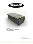
The RanOx™ booster is housed inside an extruded alloy case, as shown in the title page photographs.
Its approximate dimensions are 120 * 105 * 55 mm (length * width * height). Mounting feet occupy an
additional 20 mm each side. Extra space must be allowed for its switches, leads etc, as well as
considerable clearance for the air flow required. Its mass is approximately 1 kg.
We reserve the right to alter this case and any dimensions as required to suit our high standards.
A drilling guide/template is provided for your convenience.
11.
EMC COMPLIANCE (Radio/TV Interference)
The RanOx™ battery booster complies with the requirements of CSIPR 22 Class A.
N21629
However, if you experience any apparent interference from this device, try re-routing input/output cables
away from sensitive electronic devices and their cabling. Ensure that the negative battery terminal is
bonded to a good chassis ground, as close as possible to the auxiliary battery. If necessary, reorient or
relocate the receiving antenna away from the booster and its cabling.
Consult your dealer or the factory for further advice.
12.
WARNINGS
12.1.
DISCLAIMER:
This booster is designed specifically for use between a vehicle and a caravan/camper/trailer. It may also
be used with an auxiliary battery in a 4WD or Motorhome. If installed and programmed correctly, it will
compensate for cable losses and/or low alternator voltage, to fully charge then float a recreational
battery, with the correct voltage and current for that battery.
Using this booster for any other purpose may cause damage to the booster and/or other appliances.
Please consult your dealer or the factory to discuss many other possible applications.
This product is built from quality components using approved engineering design techniques available
at the time of construction however, the designer, assembler and dealer will not be held in any way
responsible for any damages, direct or indirect, arising from or related to this product.
Although we have made every endeavour to provide accurate and up-to-date information in this manual
and its diagrams, there may be unintentional errors or omissions.
12.2.
REVERSE POLARITY CONNECTION:
Take particular care when installing or connecting batteries, as the RanOx™ booster will be
DESTROYED by reverse polarity connection ! This is regarded as abuse of the unit.
12.3.
USER ACCESS:
There are NO user serviceable parts inside the RanOx™ booster. Opening of the case or tampering
with the unit in any way will void any warranty.
RanOx_Manual_Rev_4H1m.doc
Page 15
July 2009
RanOx™ BATTERY BOOSTER: USER MANUAL
13.
ACTUAL VOLTAGE/CURRENT CHARGING DIAGRAM
30.0
60
25.0
50
20.0
RanOx Charging 200Ah Battery Bank
from 13V8 Vehicle
40
15.0
30
10.0
20
RanOx Battery_Volt
5.0
RanOx Charge_Amp
10
RanOx AmpHour
Time (elapsed min.)
0.0
0
50
100
150
200
0
300
250
Capacity Charged (Ah)
Voltage (Volt), Current (Amp)
SHORT feed cable, after 46Ah discharge
........BULK............................/..ABSORPTION.../... FLOAT................................................................
This diagram shows a typical sequence, as the RanOx™ charges a battery through constant-current (bulk)
stage, to boost voltage (absorption) stage, then holding at float voltage. This may take minutes or
several hours, depending on the battery. This graphs actual current and voltage, using RanOx to charge
a battery-bank, in an under bonnet application (with a fixed 13.8 Volt alternator source).
14.
SUMMARY
The RanOxTM Battery Booster is proudly designed, manufactured and fully supported in Australia by
RanOx Pty. Ltd. It suits the rugged Australian conditions, where many travellers wish to spend many
days away from mains-powered sites, being self-reliant, but with an ever-increasing range of electrical
devices.
As RanOxTM is a sophisticated product, we reserve the right to improve the unit; thus the LED
behaviour, actual LCD text and symbols indicated above may vary with your particular unit. Parameter
values and Stage behaviour may also be modified to continually keep RanOxTM the “best” mobile DC
powered charger available in Australia today.
15.
CONTACT DETAILS
Alan Ransley (Director),
RanOx Pty. Ltd.
website:
Email:
Mobile:
Alan Oxenbould (Director)
ABN 28 131 212 952
PO Box 199, Lilydale
Victoria, Australia
ranox.com.au
[email protected]
0400 289 671
RanOx_Manual_Rev_4H1m.doc
3140
Page 16
July 2009
RanOx BATTERY-BOOSTER WIRING DIAGRAM (simple)
Option 1,2,3,4
This diagram is for information purposes only and is subject to change at any time.
RanOx Pty. Ltd. is NOT responsible for any damages, direct or indirect,
arising from or related to the use of this information sheet.
Red
RANOX INPUT
40A
Red
40A
for CARAVAN, CAMPER or TRAILER APPLICATION
50 AMP ANDERSON PLUG/SOCKET
INPUT
RANOX OUTPUT Positive
40A
RanOx
BOOSTER
UNIT
TWIN sheathed cable
CRANKING BATTERY
"VAN" FEED FUSE/BREAKER
OUTPUT
BATTERY-TEMPERATURE-SENSOR
Black
OPTIONAL
AUXILIARY BATTERY
The Booster should be securely mounted close to auxiliary battery,
but protected from water, dust and vibration.
The LCD display and switches should be visible/accessible.
Adequate ventilation MUST be provided around and under the RanOx.
Negative
EARTH
With option 1-4 selected, RanOx automatically detects engine running (alternator active). There must NOT be any other loads sharing either RanOx feed or connected to auxiliary
battery in this configuration. If loads must be connected to the auxiliary battery during charge, then a RanOx controlled load relay is required (see other circuits and consult User Manual).
Suitably rated fuse/s or circuit breaker/s MUST protect vehicle feeds. The booster feed wire should be al least 6 square mm size. Any join should be soldered.
For caravan/camper/trailer applications, a heavy duty connector (preferably 50 Amp Anderson style) should be used for JUST the RanOx feed.
The standard trailer plug/socket should be used should be used for any fridge feed.
In-line 40 amp fuses (provided) protect the RanOx input and output. However, the booster may be DESTROYED by reverse polarity connection of input or output !
If loads MUST be permanently connected to the auxiliary battery, consult User Manual for other suggested circuits.
RanOx also provides a Master-OFF facility, to conveniently dis-connect all loads.
If desired (to run a compressor fridge etc) an optional load changeover relay may be fitted, which will still drive all auxiliary loads whilst moving, but not waste RanOx capacity.
RANOX Pty. Ltd. ABN 28 131 212 952.
www.ranox.com.au
17 JUL 2008
RanOx BATTERY-BOOSTER WIRING DIAGRAM 4WD/MOTORHOME/MARINE: Option 1,2,3,4
This diagram is for information purposes only and is subject to
change at any time.
RanOx Pty. Ltd. is NOT responsible for any damages, direct or indirect,
arising from or related to the use of this information sheet.
OPTIONAL FRIDGE RELAY
FRIDGE FUSE ABSORPTION
The Booster should be securely mounted close to auxiliary battery,
but protected from water, dust and vibration.
The LCD display and switches should be visible/accessible.
Adequate ventilation MUST be provided around and under the RanOx.
FRIDGE ETC FEED FUSE
INPUT
RanOx
BOOSTER
UNIT
Red
40A
BLUE wire
BATTERY-TEMPERATURE-SENSOR
Black
OPTIONAL
Negative
EARTH
AUXILIARY BATTERY
40A
OUTPUT
Red
86
RANOX OUTPUT Positive
TWIN sheathed cable
CRANKING BATTERY
RANOX INPUT
FRIDGE
20A
87A
OPTIONAL LOAD CHANGEOVER RELAY
87
BROWN wire
30A
85
30
87
30
30
LOAD FUSE 1
85
86
LOAD FUSE 2
LOAD FUSE 3
85
86
VARIOUS LOADS
87
OPTIONAL BATTERY LOAD RELAY
With option 1-4 selected, RanOx automatically detects engine running (alternator active). There must NOT be any other loads sharing the RanOx feed in this configuration.
Suitably rated fuse/s or circuit breaker/s MUST protect vehicle feeds. The booster feed wire should be al least 6 square mm size. Any join should be soldered.
In-line 40 Amp fuses (provided) protect the RanOx input and output. The booster may be DESTROYED by reverse polarity connection of input or output !
If an absorption fridge circuit is connected directly to the battery under charge, this will waste over half the maximum 25 Amp RanOx output current, holding it in BOOST mode.
This usually results in overcharging and possible permanent battery damage. We recommend the optional Battery-Temperature-Sensor to help protect the battery.
However, RanOx can limit BOOST charging to 2, 3 or 4 hour, by User selection, if loads MUST be permanently connected to the battery.
Absorption style fridge current (typically 13 Amp) will rapidly flatten any battery, so should not be operated unless fed from the vehicle alternator whilst engine running.
An optional relay for an absorption fridge connection is shown. RanOx will automatically control this relay. This fridge feed wire should be AT LEAST 4 square mm size.
Fitting of the optional battery-load relay will automatically protect the auxiliary battery against excessive discharge, when stopped/camped/moored.
We recommend that all auxiliary battery loads (apart from absorption fridge) be through this relay, which can be driven by the RanOx as shown.
This also provides a Master-OFF facility, to conveniently dis-connect all loads.
If desired (to run a compressor fridge etc) an optional load changeover relay may be fitted, which will still drive all auxiliary loads whilst moving, but not waste RanOx capacity.
RANOX Pty. Ltd. ABN 28 131 212 952.
www.ranox.com.au
16 DEC 2008
RanOx BATTERY-BOOSTER WIRING DIAGRAM
4WD/CARAVAN/CAMPER: Option 1,2,3,4
This diagram is for information purposes only and is subject to
change at any time.
RanOx Pty. Ltd. is NOT responsible for any damages, direct or indirect,
arising from or related to the use of this information sheet.
87
VEHICLE
BROWN wire
BLUE wire
40A
INPUT
50 AMP ANDERSON PLUG/SOCKET
RanOx
BOOSTER
UNIT
OUTPUT
Red
87A
OPTIONAL LOAD CHANGEOVER RELAY
87
40A
BATTERY-TEMPERATURE-SENSOR
Black
EARTH
86
Red RANOX OUTPUT Positive
TWIN sheathed cable
CAR BATTERY
40A
RANOX INPUT
FRIDGE
20A
OPTIONAL
Negative
87
30
30
LOAD FUSE 1
85
86
LOAD FUSE 2
LOAD FUSE 3
85
VAN LOADS
30A
FEED FUSE
30
The Booster should be securely mounted close to van battery,
but protected from water, dust and vibration.
The LCD display and switches should be visible/accessible.
7 PIN TRAILER PLUG/SOCKET Adequate ventilation MUST be provided around and under the RanOx. 85
CARAVAN BATTERY
FRIDGE ETC FEED FUSE
OPTIONAL FRIDGE RELAY
FRIDGE FUSE ABSORPTION
86
OPTIONAL BATTERY LOAD RELAY
RANOX Pty. Ltd. ABN 28 131 212 952.
www.ranox.com.au
With option 1-4 selected, RanOx automatically detects engine running (alternator active). There must NOT be any other loads sharing the RanOx feed in this configuration.
Suitably rated fuse/s or circuit breaker/s MUST protect vehicle feeds.
We insist that a separate (preferably 50 Amp Anderson style) plug/socket is used for the RanOx booster feed; with the standard trailer (7-pin) plug/socket used for the fridge feed.
The booster feed wire should be AT LEAST 6 square mm size (preferably >= 10 sq. mm). This feed will still drop over 1 Volt at 30 Amp, with typical cable lengths. Any join should be soldered.
In-line 40 Amp fuses (provided) protect the RanOx input and output. The booster may be DESTROYED by reverse polarity connection of input or output !
If an absorption fridge circuit is connected directly to the battery under charge, this will waste over half the maximum 25 Amp RanOx output current, holding it in BOOST mode.
This usually results in overcharging and possible permanent battery damage. We recommend the optional Battery-Temperature-Sensor to help protect the battery.
However, RanOx can limit BOOST charging to 2, 3 or 4 hour, by User selection, if loads MUST be permanently connected to the battery.
Absorption style fridge current (typically 13 Amp) will rapidly flatten any battery, so should not be operated unless fed from the vehicle alternator whilst engine running.
An optional relay for an absorption fridge connection is shown. RanOx will automatically control this relay.
This fridge feed wire should be AT LEAST 4 square mm size. This feed will still drop over 0.5 Volt at 13 Amp, with typical cable lengths.
Fitting of the optional battery-load relay will automatically protect the van battery against excessive discharge, when stopped/camped.
We recommend that all caravan/camper battery loads (apart from absorption fridge) be through this relay, which can be driven by the RanOx as shown.
This also provides a Master-OFF facility, to conveniently dis-connect all loads, which is ideal for travelling/charging, unless a compressor fridge is fitted to van.
If desired (to run a compressor fridge etc) an optional load changeover relay may be fitted, which will still drive all van loads whilst driving, but not waste RanOx capacity.
16 DEC 2008
RanOx BATTERY-BOOSTER WIRING DIAGRAM
4WD/CARAVAN/CAMPER: Option 0
This diagram is for information purposes only and is subject to
change at any time.
RanOx Pty. Ltd. is NOT responsible for any damages, direct or indirect,
arising from or related to the use of this information sheet.
OPTIONAL FRIDGE RELAY
FRIDGE FUSE ABSORPTION
87
30
The Booster should be securely mounted close to van battery,
but protected from water, dust and vibration.
FRIDGE FEED FUSE 7 PIN TRAILER PLUG/SOCKET The LCD display and switches should be visible/accessible.
85
Adequate ventilation MUST be provided around and under the RanOx.
FRIDGE
20A
86
20A
Red
Red 40A
85
From
Ignition Switch DIODE
86
INPUT
50 AMP ANDERSON PLUG/SOCKET
OPTIONAL BATTERY LOAD RELAY LOAD FUSE 1
RANOX OUTPUT Positive
RanOx
BOOSTER
UNIT
40A
BATTERY-TEMPERATURE-SENSOR
Black
OPTIONAL
Negative
EARTH
87
30
LOAD FUSE 2
LOAD FUSE 3
85
VAN LOADS
RANOX INPUT
CARAVAN BATTERY
40A
BLUE wire
OUTPUT
FEED RELAY
FEED FUSE 30
87
CAR BATTERY
BROWN wire
OTHER CAR LOADS
TWIN sheathed cable
VEHICLE
86
With option 0, the booster MUST connect to the supply battery/alternator via a suitable feed relay. Failure to do so WILL result in discharging the supply battery and may damage the booster.
We recommend at least 40 Amp rating, preferably higher, particularly if other car loads are fed. Suitably rated fuse/s or circuit breaker/s should protect such feeds.
The relay energising circuit/s should be connected to the ignition circuit, so that power is only fed to the RanOx booster (and other car loads) with the engine running.
We recommend that a separate 50 Amp Anderson style plug/socket is used for the RanOx booster feed; with the standard trailer (7-pin) plug/socket used for the fridge feed.
The booster feed wire should be AT LEAST 6 square mm size (preferably >= 10 sq. mm). This feed will still drop over 1 Volt at 30 Amp, with typical cable lengths.
Other loads MAY share this feed, provided appropriate cable, fuse and relay are used. Any join should be soldered.
In-line 40 Amp fuses (provided) protect the RanOx input and output. The booster may be DESTROYED by reverse polarity connection of input or output !
Under NO circumstances should an absorption fridge circuit be connected directly to the battery under charge. This will waste over half the RanOx output current, holding it in BOOST mode.
This results in overcharging and possible permanent battery damage. We recommend the optional Battery-Temperature-Sensor to help protect the battery.
Absorption style fridge current (typically 13 Amp) will rapidly flatten any battery, so should not be operated unless fed from the vehicle alternator whilst engine running.
An optional relay for an absorption fridge connection is shown. RanOx will automatically control this relay.
This fridge feed wire should be AT LEAST 4 square mm size. This feed will still drop over 0.5 Volt at 13 Amp, with typical cable lengths.
Fitting of the optional battery-load relay will automatically protect the van battery against excessive discharge, when stopped/camped.
We recommend that all caravan/camper battery loads (apart from absorption fridge) be through this relay, which can be driven by the RanOx as shown.
This also provides a Master-OFF facility, to conveniently dis-connect all loads, which is ideal for travelling/charging, unless a compressor fridge is fitted to van.
RANOX Pty. Ltd. ABN 28 131 212 952.
www.ranox.com.au
22 JUL 2008