1
Data Concentrators
Residential
Data Concentrator
DC450
User Manual
Date: 23.11.2012
Corresponds to SW version 1.4
Filename: D000031888 DC450 User Manual en h.docx
© Landis+Gyr
D000031888 en h
Revision history
2/54
Revision history
Version
Date
Comments
a
11.06.2010
First edition
b
09.02.2011
Updated to SW version 1.2.0
c
21.04.2011
Updated to the latest document template with minor corrections (e.g.
deletion of protective earth)
d
18.07.2011
Updated Chapters 4.1.1 and 4.4: Avoid installation on south-facing walls
and direct sunshine
e
22.03.2012
Updated to SW version 1.3.0
Added a link to Chapter 10 Web interface to Chapter 5.2.6 Checking
GSM/GPRS/UMTS operation.
Updated web interface figure captions.
Added a table listing web interface pages available to “admin” users to
Chapter 10 Web interface.
Added password information to Chapter 10.3.6 Other configuration
options.
Added new figures and descriptions to Chapter 10.4 Diagnostics.
Added active alarms to Chapter 10.4 Diagnostics.
f
25.05.2012
Updated to SW version 1.3.5
Added Chapter 8 Alarms.
Added Chapter 9 Events.
Added Chapter 10.3.5 Readings configuration.
Added a description of the PLC statistics snapshot feature to Chapter
10.4 Diagnostics.
Synchronised document version indicators.
g
19.09.2012
Corrected “3-phase 230 V, no neutral” connection diagram.
Updated company name.
h
23.11.2012
Updated to SW version 1.4
Updated all screenshots
Updated all Gridstream software application names.
Reformatted all Notes, Cautions and Warnings.
Updated Figure 1. DC450 in the Gridstream system.
Added L1 to note in 4.5 Electricity network connection.
Added Chapter 5.2.1 Mounting.
Added Chapter 5.2.7 Meter response timeout (with RS-485 only).
Added new alarms to Chapter 8 Alarms.
Updated list of Web UI pages in Chapter 10 Web interface.
Added PLC device count (max. number of metering devices) to Chapter
10.2 Web UI Main page.
Added MAC address ranges to 10.3.2 PLC configuration.
Added Chapter 10.3.4 Communication failure monitoring.
Added support for S650 active alarms to Chapter 10.3.6 Other
configuration options.
Nothing in this document shall be construed as a representation or guarantee in respect of the
performance, quality or durability of the specified product. Landis+Gyr accepts no liability
whatsoever in respect of the specified product under or in relation to this document.
Subject to change without notice.
© Landis+Gyr
D000031888 en h – DC450 – User Manual
Table of Contents
3/54
Table of Contents
1
About this document ..................................................................................................................5
2
Introduction .................................................................................................................................7
2.1 Key features and benefits of the DC450 data concentrator ......................................................7
3
Safety information ......................................................................................................................8
3.1 Responsibilities ........................................................................................................................8
3.2 Safety regulations ....................................................................................................................9
4
Installation requirements .........................................................................................................10
4.1 Installation site conditions ......................................................................................................10
4.1.1 General conditions...........................................................................................................10
4.1.2 Safety notes concerning the communication module .......................................................10
4.2 SIM card requirements ...........................................................................................................11
4.3 Antennas................................................................................................................................11
4.4 Installation location ................................................................................................................11
4.4.1 Outdoor Installation .........................................................................................................11
4.5 Electricity network connection ................................................................................................11
5
Installation sequence ...............................................................................................................12
5.1 General instructions ...............................................................................................................12
5.2 Installation of the DC450 concentrator ...................................................................................12
5.2.1 Mounting .........................................................................................................................12
5.2.2 LED operation .................................................................................................................13
5.2.3 Installation of the concentrator .........................................................................................14
5.2.4 Installation of the antenna................................................................................................15
5.2.5 Checking the signal strength ...........................................................................................16
5.2.6 Checking GSM/GPRS/UMTS operation...........................................................................16
5.2.7 Meter response timeout (with RS-485 only) .....................................................................17
5.3 Installation of DC450 to the Gridstream system .....................................................................17
6
Faceplate and LEDs ..................................................................................................................18
7
Dimensions and connection diagram......................................................................................19
7.1 Dimensions ............................................................................................................................19
7.2 Connection diagram ...............................................................................................................20
8
Alarms .......................................................................................................................................21
9
Events ........................................................................................................................................23
10
Web interface .........................................................................................................................25
10.1 Connecting to the concentrator locally through LAN .............................................................28
10.2 Web UI Main page ...............................................................................................................29
10.3 Configuration .......................................................................................................................29
10.3.1 GSM/GPRS/UMTS configuration ...................................................................................29
10.3.2 PLC configuration ..........................................................................................................31
10.3.3 Repeater call .................................................................................................................32
10.3.4 Communication failure monitoring .................................................................................34
D000031888 en h – DC450 – User Manual
© Landis+Gyr
4/54
Table of Contents
10.3.5 Readings configuration ................................................................................................. 35
10.3.6 Other configuration options ........................................................................................... 38
10.4 Diagnostics .......................................................................................................................... 42
10.5 Software update through the web interface ......................................................................... 48
11
Maintenance and troubleshooting ....................................................................................... 49
11.1 Maintenance ........................................................................................................................ 49
11.1.1 Concentrator software update ....................................................................................... 49
11.1.2 Changing the communication module ........................................................................... 49
11.2 Troubleshooting ................................................................................................................... 50
11.2.1 No GSM/GPRS/UMTS connection to the DC450 .......................................................... 50
12
Decommissioning and disposal .......................................................................................... 51
13
Terms and abbreviations...................................................................................................... 52
© Landis+Gyr
D000031888 en h – DC450 – User Manual
About this document
1
5/54
About this document
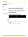
Range of validity
The present user manual applies to the DC450 Data Concentrator.
Purpose
This document describes the installation and use of the DC450 Data
Concentrator. For information on the hardware and software features of the
concentrator, see DC450 Data Concentrator Product Description.
Target group
The contents of this user manual are intended for technically qualified
personnel of energy supply companies responsible for the system planning,
installation and commissioning, operation, maintenance, decommissioning
and disposal of data concentrators.
Reference documents
This document is available in the following languages:
Language
Document number
English
D000031888
German
D000039125
Finnish
D000039115
Norwegian
D000040774
Polish
D000039232
The following documents provide more information related to the subject of
this document:
•
•
D000031887 “DC450 Product Description en”
D000031889 “DC450 Technical Data en”
D000031888 en h – DC450 – User Manual
© Landis+Gyr
6/54
About this document
Typographical conventions
The following typographical conventions are used throughout this
document:
Font
Description
Courier
Font for file names, paths and code examples.
Bold
Font style used for menu items and buttons in user
interface and for keys on keyboard.
Italics
Font style for new terminology and for references to other
documents or other parts within this document. For
example: “For more information on safety, see chapter 3
Safety information.”
Terms and abbreviations
A list of terms and abbreviations used in this document is available at the
end of this document.
© Landis+Gyr
D000031888 en h – DC450 – User Manual
Introduction
7/54
2
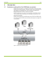
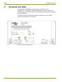
Introduction
2.1
Key features and benefits of the DC450 data concentrator
DC450 data concentrator is an intelligent concentrator for large scale meter
reading and controlling systems. The basic function of the concentrator is to
collect data from metering devices, store it and deliver the data to the
Message Max platform and on to upper level systems.
DC450 is designed to be modular in both hardware and software structure.
This modularity makes introducing new technologies and protocols in the
future easy and flexible.
DC450 communicates with the HES system using TCP/IP and GPRS. With
the metering devices DC450 uses cost efficient and simple low voltage PLC
communication.
Figure 1. DC450 in the Gridstream system
D000031888 en h – DC450 – User Manual
© Landis+Gyr
8/54
3
Safety information
Safety information
The following symbols are used to draw your attention to the relevant
danger level, i.e. the severity and probability of any danger, in the individual
sections of this document.
Warning
Used to indicate a dangerous situation that could cause bodily injury or
death.
Caution
Used to indicate a situation/ action that could result in material damage or
loss of data.
Note
Used to indicate general guidelines and other useful information.
In addition to the danger level, safety information also describes the type
and source of the danger, its possible consequences and measures for
avoiding the danger.
3.1
Responsibilities
The owner of the device – usually the utility – is responsible that all persons
engaged on work with devices:
•
•
•
Have read and understood the relevant sections of the user manual.
Are sufficiently qualified for the work to be performed.
Strictly observe the safety regulations and the operating information in
the individual chapters.
In particular, the owner of the devices bears responsibility for the protection
of persons, prevention of material damage and the training of personnel
(Landis+Gyr. provides training courses for this purpose on specific
equipment; please contact the relevant agent if interested).
© Landis+Gyr
D000031888 en h – DC450 – User Manual
Safety information
3.2
9/54
Safety regulations
The following safety regulations must be observed at all times:
•
•
•
•
•
•
•
This equipment does not contain a disconnection device. Means for
disconnection from the supply must be provided as part of the building
installation. Do not work on the equipment unless the supply is
disconnected. If disconnection is done by removal of fuses or other cutouts, the removed disconnection devices must be kept secure from
replacement while work is performed. If disconnection is provided by a
switch, the switch shall conform to the requirements of IEC 947-1 and
IEC 947-3 or equivalent.
This equipment does not contain an overcurrent protection device.
Overcurrent protection must be provided as part of the building
installation. Maximum overcurrent device rating is 125 Amp at 415
Volts, conforming to the requirements of BS1361, or equivalent. The
network connections must not be under voltage during installation or
when opening. Contact with live parts is dangerous to life. The relevant
main fuses should therefore be removed and kept in a safe place until
the work is completed, so that other persons cannot replace them
unnoticed.
Only suitably trained and qualified personnel shall be allowed to work
on the equipment. Local safety standards shall be observed and shall
take precedence over these regulations in points of conflict.
The devices must be held securely during installation. They can cause
injuries if dropped.
Devices that have fallen must not be installed, even if no damage is
apparent, but must be returned for testing to the service and repair department responsible (or the manufacturer). Internal damage can result
in functional disorders or short-circuits.
The devices must on no account be cleaned with running water or with
high-pressure devices. Water penetrating can cause short-circuits.
The device terminal cover should be secured in place before any load
is supplied.
D000031888 en h – DC450 – User Manual
© Landis+Gyr
10/54
Installation requirements
4
Installation requirements
4.1
Installation site conditions
4.1.1
General conditions
The installation site must meet the requirements of the device’s protection
class (IP51) and the operating temperature range (-25 … +60°C). Other
temperatures are possible with external housing and additional
warming/cooling. Avoid installing the device on south-facing walls and
direct sunlight. If necessary, use an additional shield or visor to protect the
outdoor installation case from direct sunlight (shield not provided by
Landis+Gyr).
There must be no harmful, corrosive gases or dust on the installation site.
4.1.2
Safety notes concerning the communication module
DC450 can contain a 2G or 3G module. Due to the possibility of radio
frequency (RF) interference, it is very important to follow any regulations
regarding the use of radio equipment at the place of installation.
There may be a hazard associated with the operation of a 2G or 3G module
close to inadequately protected personal medical devices such as hearing
aids and pacemakers. Consult the manufacturer of the medical device to
determine if it is adequately protected.
Operation of the 2G or 3G module close to other electronic equipment may
cause interference if the equipment is inadequately protected. Observe any
warning signs and manufacturer’s recommendations. Make sure that the
distance between the GSM/UMTS antenna and any electronic equipment is
at least 60 cm.
The following list contains sites referred to in the general safety notes of the
2G or 3G module manufacturer. If you are planning to install the DC450 in
the immediate vicinity of any of the following sites, please contact
Landis+Gyr.
•
•
•
•
Airports
Service stations
Hospitals or any other places where medical equipment may be in use.
Fuel depots, chemical plants, or other locations with a risk of explosion,
or sites where blasting work is in progress
Changing the communication module during DC operation:
Before the communication module can be replaced, it must be disabled in
the web interface, see Chapter 11.1.2 Changing the communication
module. Removing the module before it is disabled can cause malfunction
of the DC and corrupted data.
© Landis+Gyr
D000031888 en h – DC450 – User Manual
Installation requirements
4.2
11/54
SIM card requirements
The SIM card must support GPRS communication. It is recommended to
check with the operator that the SIM card’s data baud rate and other
functions are compatible with the devices the DC450 will be used with.
The SIM card’s PIN code enquiry must be switched off. See Chapter 5.2.6
Checking GSM/GPRS/UMTS operation.
4.3
Antennas
The communication module for DC450 concentrator has a built in GSM
antenna. If necessary, an external antenna can be installed to ensure
communication. Check the antenna options available from the document
GSM Antenna Overview.
4.4
Installation location
The DC450 can be installed directly to a wall. Fix the cables to the wall with
a fastener under the device’s terminal block cover; do not leave the cables
hanging free.
The DC450 is intended for indoor use, but outdoor installation is possible
with external housing and warming/cooling. Avoid installing the device on
south-facing walls and direct sunlight.
4.4.1
Outdoor Installation
When the installation environment exceeds the DC450 protection class,
you must use an outdoor installation case. You can order the DC450
concentrators so that they are ready-installed in the cases or so that the
concentrators and cases are delivered separately.
The case’s connection to electricity network is 3 x 230 V. Neutral of the
case must always be connected to the power line network. Pre-fuses (16 A)
can be ordered ready-installed in the delivery or installed on site. Check if
the connection cable requires smaller fuses.
For more information, see Outdoor Installation Case Installation Manual.
4.5
Electricity network connection
The connection to the power line network is 230 V, 3 x 230 V or 3 x
230/400 V. See also Chapter 7.2 Connection diagram.
You must always connect the neutral and L1 of the concentrator to the
power line network. If there is no neutral in the network, you must connect
the DC according to Chapter 7.2 Connection diagram.
D000031888 en h – DC450 – User Manual
© Landis+Gyr
12/54
Installation sequence
5
Installation sequence
5.1
General instructions
Keep low voltage cables, e.g. Ethernet cable, separated from cables with a
nominal voltage of 230 Vac. Make sure the cable insulation reaches inside
the terminal block cover; do not strip cables more than 40 mm.
Do not leave the cables hanging free. Use a fastener to fix them to the wall
and to prevent draw.
5.2
Installation of the DC450 concentrator
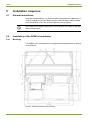
5.2.1
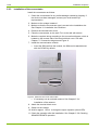
Mounting
The DC450 can be installed with its integrated mounting brackets or directly
to the DIN rail.
Figure 2. DC450 mounting bracket positions
© Landis+Gyr
D000031888 en h – DC450 – User Manual
Installation sequence
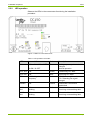
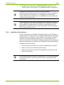
5.2.2
13/54
LED operation
Observe the LEDs in the concentrator front during the installation
procedure.
Figure 3. LEDs on concentrator front
Table 1. LED operation in DC450
LED
Interval / State
Colour
Description
ON
250ms ON / 250ms OFF,
Green
Waiting super capacitor to be
charged;
Normal operation
2s ON / 2s OFF
CPL Snd
ON
Green
Transmitting PLC data
CPL Rcv
ON
Red
Receiving PLC data
RSL
ON/blinking at variable
frequency
Yellow
GSM field strength level, see
5.2.5 Checking the signal
strength
OPM/Li
ON
Yellow
GPRS/UMTS connection
established
LAN1
Act
ON,
Blinking
Yellow
Ethernet cable connected;
Receiving or transmitting data
LAN2
Act
ON,
Blinking
Yellow
Ethernet cable connected;
Receiving or transmitting data
D000031888 en h – DC450 – User Manual
© Landis+Gyr
14/54
5.2.3
Installation sequence
Installation of the concentrator
Install the concentrator as follows:
1. Check the concentrator for any visible damage caused by shipping. If
the device has been damaged, contact your local Landis+Gyr
representative.
2. Make sure the voltage is not on!
3. Make sure that the concentrator type is correct to the installation site.
See Chapter 4.1 Installation site conditions.
4. Remove the terminal block cover.
5. Place the concentrator on the wall. Fix it to the wall with screws.
6. Make the required wiring according to the connection diagram, which is
located on the reverse side of the terminal block cover. See also
Chapter 7.2 Connection diagram and Figure 8.
7. Install the communication module.
•
Insert the SIM card into the module, the SIM card is not delivered
with the DC450 by default.
Figure 4. SIM card slot on the 2G modem
•
If necessary use an external antenna. See Chapter 5.2.4
Installation of the antenna.
8. Attach the terminal block cover.
9. Switch on the voltage.
10. Wait for approx. 10 min. to charge the super capacitor (check LED).
11. Check the operation after the installation. See Chapter 5.2.6 Checking
GSM/GPRS/UMTS operation.
© Landis+Gyr
D000031888 en h – DC450 – User Manual
Installation sequence
15/54
12. Configure the concentrator’s GSM/GPRS/UMTS connection to the
metering system. See Chapter 10.3 GSM/GPRS/UMTS configuration.
Changing the communication module during DC operation:
Before the communication module can be replaced, it must be disabled in
the web interface, see Chapter 11.1.2 Changing the communication
module. Removing the module before it is disabled can cause malfunction
of the DC and corrupted data.
At the first start-up of the DC450, the backup super capacitor is empty. In
order to guarantee a safe shut-down operation, it is necessary to load the
super capacitor for approximately 10 minutes. During this time it is not
possible to access the DC over the web interface (the “ON” LED will blink
250 ms ON and 250 ms OFF).
5.2.4
Installation of the antenna
The DC comes with a pre-installed ¼ lambda antenna on the 2G modem,
located under the terminal block cover. External GSM antennas that can be
installed indoors or outdoors are also available. If the antenna is installed
outdoors, it should be placed so that snow, ice or other debris cannot
collect on the antenna. For detailed installation instructions of the antennas
delivered with Landis+Gyr products, see GSM/UMTS Antenna Data Sheet.
Installing an external antenna:
1. Connect the antenna cable to the module’s GSM antenna connector.
2. Search for the point of sufficient signal strength.
3. Attach the antenna to the surface according to the instructions of the
specific antenna type.
Do not place the antenna inside a closed metal box! The external antenna
must be at least 60 cm from any electronic device including the DC450
concentrator.
D000031888 en h – DC450 – User Manual
© Landis+Gyr
16/54
5.2.5
Installation sequence
Checking the signal strength
Place the antenna so that the GSM signal strength is sufficient. Weather
may influence the signal strength. If the signal is just above the limit on
clear weather, it may be lost altogether when the weather is bad.
To check the signal strength, check the RSL LED on the concentrator front.
LED
Field strength
Explanation
OFF
GSM FSL* is between
0 - 5 or error
Insufficient signal or no
signal at all
200ms ON / 1800ms
OFF
GSM FSL* is between
6–9
Very weak signal, may
be lost at times
200ms ON / 800ms
OFF
GSM FSL* is between
10 – 14
Weak signal, may be
lost at times
ON
GSM FSL* is between
15 – 31
Sufficient signal
strength
*FSL = Field strength level.
5.2.6
Checking GSM/GPRS/UMTS operation
When you have installed the SIM card, antenna and connected power to
the DC450, check the OPM/Li LED to check if the concentrator has a
connection to the GSM/UMTS network.
If the DC450 is not able to establish a connection to the network, check the
following on the web interface (for more information on the web interface,
see Chapter 10 Web interface:
Figure 5. Configuration – GSM – Radio band config page
© Landis+Gyr
D000031888 en h – DC450 – User Manual
Installation sequence
17/54
1. Make sure the requested radio band is activated.
2. Move the DC450’s antenna to find a location where the signal strength
is sufficient. Additionally, a mobile phone can be used to check that the
installation location in general is within GSM/GPRS/UMTS signal
range, but note that some phones are 3G enabled. The availability of a
3G network does not guarantee a GPRS/2G network and vice versa.
3. Check that the SIM card is properly installed.
4. Switch off the PIN code request of the SIM card. Remove the SIM card
from the concentrator and install it to a GSM mobile phone to switch off
the request (see the phone’s instructions) and reinstall it to the
concentrator.
If the GSM/GPRS/UMTS module is still not operational, it could be that the
APN information has not been pre-defined at production. Contact your local
Landis+Gyr representative for more information.
5.2.7
Meter response timeout (with RS-485 only)
When connecting any device to DC450 through the RS-485 connection,
this device needs to be configured so that the response timeout is greater
or equal to 200 ms.
For instance, in the case of S650 Smart Grid Terminal, you have to make
sure that the value of attribute “ResponseTime” of object
HDLCsetupDataCh1 (0-1:22.0.0.255), class [23-0-1-0] in the device
configuration is set to 200.
5.3
Installation of DC450 to the Gridstream system
The field installation does not include any system installation steps.
Information of DC450 concentrators is entered in a CSV file to the
Gridstream system through the AIM/HES Application Manager. For more
information, see AMR User’s Manual.
D000031888 en h – DC450 – User Manual
© Landis+Gyr
18/54
6
Faceplate and LEDs
Faceplate and LEDs
The nameplate of DC450 concentrator has information on the
manufacturer, CE marking, required voltage and frequency, transceiver
type and type of the device. Below is an example of the information marked
on the nameplate.
The device has six LED indicators visible on the front. See 5.2.2 LED
operation for description of functions.
Figure 6. Faceplate and markings
© Landis+Gyr
D000031888 en h – DC450 – User Manual
Dimensions and connection diagram
7
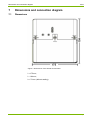
Dimensions and connection diagram
7.1
Dimensions
19/54
Figure 7. Dimensions of the DC450 Concentrator
L =175 mm;
l = 184 mm;
h = 72 mm (without sealing)
D000031888 en h – DC450 – User Manual
© Landis+Gyr
20/54
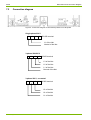
7.2
Dimensions and connection diagram
Connection diagram
Figure 8. Connection diagram of the DC450 printed on the faceplate
Single phase 230 V
N
L1
L2
L3
DC450 terminal
L1 of the Net
Neutral of the Net
3-phase 230/400 V
N
L1
L2
L3
DC450 terminal
L3 of the Net
L2 of the Net
L1 of the Net
Neutral of the Net
3-phase 230 V, no neutral
N
L1
L2
L3
DC450 terminal
L3 of the Net
L2 of the Net
L1 of the Net
© Landis+Gyr
D000031888 en h – DC450 – User Manual
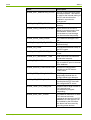
Alarms
8
21/54
Alarms
The concentrator keeps a log of internal alarms. Longer error conditions are
reported as alarms, which are set on and off as the conditions appear and
disappear. The alarms can be read from the web interface. The DC can
store up to 128 simultaneous alarms in the alarm log.
Alarm
Description
ALARM_RTC_FAULT
The RTC chip has
malfunctioned.
ALARM_OVER_TEMPERATURE
The internal temperature of the
DC is above the high alarm
limit.
ALARM_UNDER_TEMPERATURE
The internal temperature of the
DC is below the low alarm limit.
ALARM_POWER_CUT
The DC has lost power.
ALARM_MODEM_UNREACHABLE
The DC cannot establish a
connection to the internal
GSM/GPRS modem.
ALARM_NO_SIM
No SIM card has been installed.
ALARM_PIN_CODE
The SIM card is asking for a
PIN code. The DC does not
support PIN codes. The PIN
code prompt must be switched
off on the SIM card before
installation.
ALARM_ETHERNET_CABLE
The Ethernet cable is not
connected.
ALARM_LOW_DISK_SPACE
Free space on the flash
memory drive is below the
alarm limit.
ALARM_LOW_INODES
The number of free i-nodes on
the flash memory drive is below
the alarm limit.
ALARM_GSM_CONNECTION_DOWN The GSM/GPRS connection is
down.
ALARM_ETHERNET_DOWN
The Ethernet connection is
down.
ALARM_PLAN_MAC_NOT_DEFINED
No PLAN MAC address has
been defined and therefore PLC
communications are down.
ALARM_PLAN_NO_SYNCRO
The DC is unable to
synchronise with the PLAN
network.
D000031888 en h – DC450 – User Manual
© Landis+Gyr
22/54
© Landis+Gyr
Alarms
Alarm
Description
ALARM_UNIT_SIMULATOR_ACTIVE
The DC is using the PLC meter
simulation feature. This feature
is used for the internal testing of
the DC and should not be
enabled in a production
environment.
ALARM_LOW_FREE_MEMORY
The DC is running low on
memory.
ALARM_LOAD_AVERAGE_EXCEED
Some process on the DC is
taking up more processor time
than allowed. Under some
circumstances, load average
can be exceeded temporarily.
ALARM_WEAK_GSM_SIGNAL
The GSM field strength is too
low.
ALARM_PLAN_OUT_OF_ORDER
The PLAN chip is
malfunctioning.
ALARM_LID_OPEN
The lid (terminal block cover) of
the DC is open.
ALARM_LOCAL_ETHERNET_UP
The local Ethernet interface is
in use.
ALARM_RTC_INCORRECT_TIME
Real time clock time has been
found to be incorrect.
ALARM_DB_FAILURE
At least one application on the
DC is unable to open its internal
SQL database.
ALARM_INVALID_CONFIGURATION
At least one configuration
variable on the DC has an
invalid value.
ALARM_ODEP_LOGIN_BLOCKED
ODEP login has been
temporarily blocked due to
multiple failed login attempts.
ALARM_NTP_FETCH_FAULT
The DC is unable to
synchronise its RTC time with
the configured NTP server.
ALARM_TEMP_PLC_COM_ERR
Indicates that a large number of
PLC devices have
simultaneously stopped
responding.
ALARM_HIGH_UNIT_COUNT
The absolute maximum of 2500
PLC devices has been
registered and stored in the DC
database. No new devices can
be installed by the DC before
this alarm has been reset by
removing some devices.
D000031888 en h – DC450 – User Manual
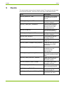
Events
9
23/54
Events
The concentrator keeps a log of internal events. The event log can be read
from the web interface. The size of the event log is 1000 latest events.
Event
Description
NOTICE_MASTER_TIME
A change in RTC master
time has been forced on
the DC.
NOTICE_TIME_CHANGED
The RTC time on the DC
has been changed.
NOTICE_TIME_NOT_CHANGED
The RTC time on the DC
has not been changed,
because the time shift
exceeded the limit.
NOTICE_STARTUP
The operating system of
the DC has started up.
NOTICE_CONFIG_CHANGED
Configuration of the DC
has been changed.
NOTICE_SW_UPDATE
The firmware of the DC
has been updated.
NOTICE_ODEP_CONNECTION_TIMEOUT
An ODEP connection has
timed out.
NOTICE_ODEP_CONNECTION_ERROR
There has been an error in
establishing an ODEP
connection.
NOTICE_PUSH_CONNECT_ERROR
There has been an error in
establishing a push
connection with
MessageMax.
NOTICE_PUSH_SENDING_ERROR
There has been an error
during the sending of push
data.
NOTICE_PUSH_COLLECT_ERROR
There has been an error in
gathering the data that
should be pushed.
NOTICE_INVALID_ODEP_FRAME
An invalid ODEP frame
has been received.
NOTICE_SMS_RECEIVED
An SMS message has
been received by the DC.
NOTICE_CALL_RECEIVED
A wake-up call has been
received by the DC.
NOTICE_MODEM_CONNECTION_RESET
The GSM/GPRS
connection was reset.
D000031888 en h – DC450 – User Manual
© Landis+Gyr
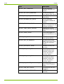
24/54
Events
Event
Description
NOTICE_UNIT_REMOVED
A meter has been
explicitly removed from
the DC.
NOTICE_ALL_DATA_REMOVED
All collected data has
been deleted from the DC.
NOTICE_PLAN_NOT_RESPONDING
The PLAN chip is not
responding.
NOTICE_RELEASE_ALL_UNITS
The DC has been
requested to release all
meters.
NOTICE_PROCESS_WD_FAIL
A process has failed to
reply to a request from the
software watchdog.
NOTICE_TEMP_READ_FAILURE
Reading the internal
temperature of the DC has
failed.
NOTICE_USER_LOGIN
A user has logged in a
terminal connection on the
DC.
NOTICE_SMS_SEND
An SMS message has
been sent by the DC.
NOTICE_OUT_OF_MEMORY
DC has run out of free
RAM. If this event occurs,
DC will do a recovery
reboot.
NOTICE_RECOVERY_DONE
Software recovery has
occurred.
NOTICE_TOO_MANY_FDS
Too many open file
descriptors have been
detected. If this event
occurs, DC will do a
recovery reboot.
NOTICE_TOO_MANY_PIDS
Too many running
processes have been
detected. If this event
occurs, DC will do a
recovery reboot.
NOTICE_SW_UPDATE_DOWNLOAD_FAIL Update package download
from FTP/HTTP server
failed.
© Landis+Gyr
NOTICE_USB_DEV_ADDED
A USB device has been
plugged in.
NOTICE_USB_DEV_REMOVED
A USB device has been
removed.
D000031888 en h – DC450 – User Manual
Web interface
10
25/54
Web interface
DC450 has an internal web user interface that can be accessed in two
ways:
•
•
Through the local Ethernet connection (mainly for initial system
interface configuration to establish communication with the metering
system). For more information, see 10.1 Connecting to the
concentrator locally through LAN.
Through an uplink connection (GPRS/UMTS or Ethernet) after it is
configured and operational.
To ensure that the system and concentrator have the same configuration
data, it is recommended to do other concentrator configurations through the
metering system.
Compatible web browsers:
Mozilla Firefox (latest version), JavaScript must be enabled
MS Internet Explorer (latest version), JavaScript must be enabled
Other browsers may work but have not been tested.
The web interface can be used to configure a single concentrator. For
configuring or updating a larger amount of concentrators at once, Device
Management must be used, see Device Management User Manual.
Service personnel can also use the web interface for diagnostics and
troubleshooting. Alarms, events, statistics and log data collected by the DC
as well as data read from the meters can be previewed in the web
interface.
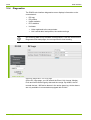
The following web interface pages are available to “admin” users:
Main
Configuration
Ethernet
Basic configuration
GSM
GSM configuration
GPRS configuration
SMS configuration
Radio band configuration
PLC
Control
Basic configuration
D000031888 en h – DC450 – User Manual
© Landis+Gyr
26/54
Web interface
Discovery configuration
Repeater call configuration
Communication failure monitoring
Meter installation / Alarm seek mode
Push
Triggers
View push profiles
View push profiles of a meter
View push profiles of devices
View profile selectors
RTC
Set time
Basic configuration
NTP configuration
Serial server
Basic configuration
Readings
Configuration
Reading profiles
Bindings
View profiles of devices
View profile selectors
Reading delay configuration
Security
Authentication
Firewall
Diagnostics
DC Logs
DC Profiles
Uplink
Modem statistics
Ethernet statistics
Serial server statistics
ODEP statistics
Push statistics
Connection test
© Landis+Gyr
D000031888 en h – DC450 – User Manual
Web interface
27/54
TLS Proxy
PLC
Statistics
Units summary
Units PLAN summary
Registration history
Unit data
Reading profile
Time status
Series
Event logs
Register
Reading statistics
Software update
Version history
Update history
Update log
SW Update
SW Update job
FW Update jobs
Maintenance
Data management
Application control
Push activation
PLC utils
Debug package
D000031888 en h – DC450 – User Manual
© Landis+Gyr
28/54
10.1
Web interface
Connecting to the concentrator locally through LAN
To connect to the concentrator for initial configuration you need:
•
•
A laptop computer with an Ethernet connection (100 Mb/s or
1000 Mb/s)
Ethernet crossover cable.
Creating the connection:
1. Connect the Ethernet cable to your laptop’s Ethernet port.
2. Connect the Ethernet cable to the concentrator’s LAN2 Ethernet port.
3. The concentrator’s default IP address is 10.0.0.2. Configure your
laptop IP address to be in the same network, e.g. 10.0.0.1 with
subnet mask 255.255.255.0. Check your operating system manual
for instructions on how to define IP addresses.
4. When the LAN2 LED on the concentrator faceplate is lit or flashing,
connection has been established between the concentrator and your
laptop.
5. Open the web browser and enter the concentrator IP address to the
address row.
6. The browser opens an authentication window. Enter the username and
password provided by your system admin or Landis+Gyr
representative.
7. The main page of the concentrator’s web interface is opened in your
browser.
The concentrator web interface can also be accessed over GPRS. You
need a laptop computer with a connection to the same GPRS network the
concentrators are in. Otherwise proceed as with LAN connection.
© Landis+Gyr
D000031888 en h – DC450 – User Manual
Web interface
10.2
29/54
Web UI Main page
Figure 9. Concentrator’s web interface main page
PLC device count:
Each concentrator can handle up to 2500 metering devices. This is a fixed
limit meaning that the DC will not install any more PLC devices once it has
2500 devices in its database.
Poor PLC network quality, long distances and the amount of data collected
per meter can substantially decrease the practical number of nodes before
the theoretical maximum limit is reached.
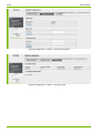
10.3
Configuration
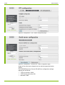
10.3.1 GSM/GPRS/UMTS configuration
If not configured in production, the initial GSM/GPRS configuration must be
done locally to establish communication with the metering system. After
communication is operational, other configurations can be done from the
system. SMS configuration is not necessary at this point; it can also be
configured later.
Changing the communication module during DC operation:
Before the communication module can be replaced, it must be disabled in
the web interface, see Chapter 11.1.2 Changing the communication
module. Removing the module before it is disabled can cause malfunction
of the DC and corrupted data.
D000031888 en h – DC450 – User Manual
© Landis+Gyr
30/54
Web interface
Figure 10. Configuration – GSM – GSM config page
1. First select CONFIGURATION and then GSM in the Main Menu on the
left. The GSM CONFIG page is displayed.
2. Set connection type as Static GPRS (always on).
3. Click Send to send the parameters to the concentrator.
4. Select GPRS CONFIG from the top of the page.
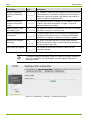
Figure 11. Configuration – GSM – GPRS config page
5. On the GPRS CONFIG page, you can enter the APN address of the
local GSM operator to the dialog.
6. If the GSM operator requires the username and password information
for GPRS communication, also enter the Username and Password.
You can also enter a PING IP address and parameters for the
Connection test or reset scheduling.
7. Click Send to send the parameters to the concentrator.
8. After you have entered all the configuration data, return to the GSM
CONFIG page and click Restart. The new settings will take effect after
restarting.
© Landis+Gyr
D000031888 en h – DC450 – User Manual
Web interface
31/54
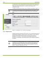
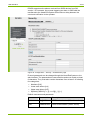
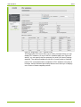
10.3.2 PLC configuration
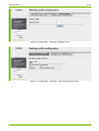
Figure 12. Configuration ‒ PLC – Basic config page for PLAN(+) configuration
To start PLC communication, the MAC address of the DC must be set. The
first PLC MAC address in a PLC network is C00 [HEX] (input value for C00
[HEX] = 0x0C00). For the data concentrator, the MAC address range is
from 0xC00 to 0xDFF. For the meter, the MAC address range is from
0x001 to 0xBFF. If necessary, the MAC address range of the meters can
be restricted from the DC using the “First unit MAC address” parameter.
D000031888 en h – DC450 – User Manual
© Landis+Gyr
32/54
Web interface
The baud rate for PLC communication must be configured according to the
used meter type (PLAN 1200 bps or PLAN+ 2400 bps). This can be done
either from the metering system or on the DC web interface PLC
configuration page.
To make sure that remote meters can be reached, set maximum credit to 7.
It is always recommended to do the configuration from the system. This
ensures that the concentrator and system have the same configuration
data.
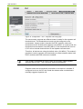
Figure 13. Configuration ‒ PLC ‒ Discovery config page
10.3.3 Repeater call
Repeater call was introduced in SW version 1.2.0. It is a procedure that can
automatically manage the repeater state of the modules in a PLC network.
Repeater call optimises communication by reducing the number of
repeaters to a minimum. The interval for the automatic repeater call
procedure is configurable. Automated repeater call functionality is disabled
by default.
Be careful when enabling repeater call in a network. Whenever you enable
a repeater call, you should monitor network behaviour for a few days. In
case network behaviour deteriorates, you need to roll back and set all
meters back to repeater mode, which is a manual procedure. For more
details, contact your field engineer or PM.
© Landis+Gyr
D000031888 en h – DC450 – User Manual
Web interface
33/54
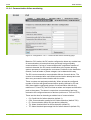
Figure 14. Configuration ‒ PLC ‒ Repeater call config page
The concentrator supports two different kinds of scales for the repeater call
threshold level. This threshold level mode can be configured on the
concentrator. Legacy mode is intended for E35C modules, where the
threshold level is a scaled value between 0 and 65535. In normal mode, the
threshold level is between 0 and 255 (dBuV). If the threshold level is set to
0, DC will not include threshold level in the repeater call command.
Therefore, all devices are using the default value (104 dBuV). This makes it
possible to use the repeater call functionality in mixed networks where both
E35C modules and E450 meters are installed.
If the PLAN(+) bandwidth is heavily used, do not select “Read repeater
statuses after the call”. This consumes additional bandwidth.
Repeater states are automatically read when a new device is installed. If
configured to do so, the DC also reads the statuses after a scheduled or
manually triggered repeater call.
D000031888 en h – DC450 – User Manual
© Landis+Gyr
34/54
Web interface
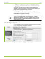
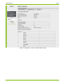
10.3.4 Communication failure monitoring
Figure 15. Configuration ‒ PLC ‒ Communication failure monitoring page
Based on PLC statics, the DC can be configured to detect any sudden loss
of communications to meters that have previously had good quality
communications. If a loss of communication with a significant number of
meters is detected, the DC sends a notification to the system allowing
system operators to investigate the root cause. Problems in the distribution
network, such as feeder or phase outages, can be detected this way.
The DC counts consecutive communication failures for each device. The
counter is incremented after each failed communication attempt and reset
after every successful communication with the meter.
These counters are analysed periodically. When at least the configured
number of devices with good communication quality (defined by CL and
CQL) have had the configured number of communication failures (the
maximum of TU and TP), the DC will set an alarm and request a notification
push to the system. The alarm is reset when communication has been
restored to the configured amount of devices (minimum of TUC and TPC).
These are the rules for detecting a sudden loss of communication:
•
•
•
•
•
© Landis+Gyr
CL: Credit limit for failure detection (default 1)
CQL: Communication quality limit for failure detection (default 70%)
FL: Communication failure limit per device (default 4)
TU: Alarm threshold limit for failure detection (default 3)
TP: Alarm threshold percentage limit for failure detection (default 5%)
D000031888 en h – DC450 – User Manual
Web interface
35/54
•
•
TUC: Alarm threshold limit for restored communication (default 2)
TPC: Alarm threshold percentage limit for restored communication
(default 4%)
CL and CQL are used to define the sample meter population to be
monitored. FL defines the number of consecutive failures required for a
meter to be registered as temporarily unreachable.
TU, TP, TUC and TPC are thresholds that define the trigger point for
notification. The percentage means the percentage of meters with good
communication as defined by CL and CQL.
There is no field experience with this functionality yet. The default
parameters are theoretical assumptions. Be aware that fine tuning will
always be necessary. There is no default parameter set that will fit all
network sizes and qualities.
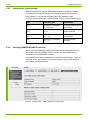
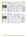
10.3.5 Readings configuration
If PLAN capacity is an issue, Readings configuration needs to be changed.
In most cases, however, no change is necessary.
Figure 16. Configuration ‒ Readings ‒ Configuration page
D000031888 en h – DC450 – User Manual
© Landis+Gyr
36/54
Field name
Web interface
Value
Description
Minimum values per
request (0=automatic
mode)
1
The number of values the DC bundles in one request under
normal operation. If this value is higher than the number of
“Maximum values per request” (see below), the number of
maximum values is used by the DC.
Maximum values per
request (0=automatic
mode)
0
The maximum number of values the DC bundles in case of
a backlog (the value should be 0 or higher, or equal to
“Minimum values per request”.
Maximum parse count
per reading cycle
10
The maximum number of requests the DC does on a single
unit before moving on to the next unit.
Assume compression on
time stamps
1
If compact read is active on all meters for all load profiles,
this value should only be set to 1. It affects the automatic
calculation of minimum or maximum values per request.
Delay before readings
(seconds)
30
The delay in seconds that the DC waits before sending
requests to profiles in order to avoid requesting data that is
not yet present in the meter.
Retry count per request
4
The number of retries the DC does in case of a nonsuccessful request.
To optimise load profile reading, “Minimum values per request” should be
set to “0” (automatic). For more details, see the Capacity Calculator or
application notes.
Figure 17. Configuration ‒ Readings ‒ Reading profiles page
© Landis+Gyr
D000031888 en h – DC450 – User Manual
Web interface
37/54
Figure 18. Configuration ‒ Readings ‒ Bindings page
Figure 19. Configuration ‒ Readings ‒ View profile selectors page
D000031888 en h – DC450 – User Manual
© Landis+Gyr
38/54
Web interface
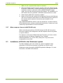
10.3.6 Other configuration options
It is always recommended to do the configurations from the system. This
ensures that the concentrator and system have the same configuration
data.
However, the concentrator web interface has other configuration options
available. It is not recommended to do configuration tasks directly on the
concentrator; these should rather be used for verification and diagnostics.
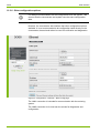
Figure 20. Configuration ‒ Ethernet ‒ Basic config page
The LAN1 connection is intended for communication with the metering
system.
The LAN2 connection is for local service access for diagnostics and
configuration.
© Landis+Gyr
D000031888 en h – DC450 – User Manual
Web interface
39/54
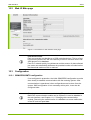
Figure 21. Configuration ‒ Push ‒ Triggers page
Changing the push configuration on the concentrator may cause problems.
It is recommended to do push configuration from the metering system to
ensure both system and concentrator have the same configuration data.
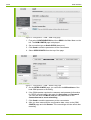
Figure 22. Configuration ‒ RTC ‒ Set time page
D000031888 en h – DC450 – User Manual
© Landis+Gyr
40/54
Web interface
Figure 23. Configuration ‒ RTC ‒ Basic configuration page
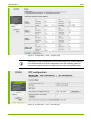
Figure 24. Configuration ‒ Serial server ‒ Basic configuration page
Usage of the serial server depends on the devices supported by the
system.
For E650/S650 devices, Remote RS-485 bus configuration settings
typically are as follows:
•
•
•
© Landis+Gyr
TCP port number: 23200
TCP timeout (seconds): 600
Baudrate: 9600
D000031888 en h – DC450 – User Manual
Web interface
41/54
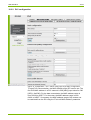
DC450 supports active alarms received from S650 devices from SW
version 1.4.0 onwards. Any events triggering an alarm in S650 shall be
transferred to the Head-End System with minimum delay between the
event and notification to the operator.
Figure 25. Configuration ‒ Security ‒ Authentication page
Protocol passwords can be changed though the Head-End System or the
web interface. The passwords are case sensitive and must contain at least
8 characters. They must also contain characters from at least 3 of following
four categories:
•
•
•
•
Numbers [0-9]
Lower-case letters [a-z]
Upper-case letters [A-Z]
Symbols [!"#$%&'()*+,.][/:;<=>?@^_\`{|}~-]
Default usernames and passwords:
Username
Password
Description
admin
QL@K1Thl
HTTP authentication (DC web interface).
user
IVM08cd-K8of
ODEP authentication (ODEP server).
D000031888 en h – DC450 – User Manual
© Landis+Gyr
42/54
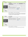
10.4
Web interface
Diagnostics
The DC450 web interface diagnostics menu displays information on the
concentrator’s:
•
•
•
•
•
DC logs
DC profiles
Uplink statistics
PLC statistics
Unit data
•
•
Units registered to the concentrator
Unit’s serial data, load profiles, time and event logs
Unit metering data is only available for diagnostics. It can be viewed on the
Diagnostics/Unit data pages, but not exported for local reading.
Figure 26. Diagnostics ‒ DC Logs page
On the DC Logs page, you can search the Event, Unit change, Modem,
Push and Active alarm logs by date and time range. By default, the DC
records the last 1 000 active alarms in the active alarm log. Active alarms
are only available in concentrators equipped with PLAN+.
© Landis+Gyr
D000031888 en h – DC450 – User Manual
Web interface
43/54
Figure 27. Diagnostics ‒ Uplink – Modem statistics page
D000031888 en h – DC450 – User Manual
© Landis+Gyr
44/54
Web interface
Figure 28. Diagnostics ‒ Uplink – Connection test page
Figure 29. Diagnostics ‒ Uplink – TLS proxy page
© Landis+Gyr
D000031888 en h – DC450 – User Manual
Web interface
45/54
Figure 30. Diagnostics ‒ PLC – Statistics page
The Diagnostics PLC menu offers you a variety of pages where you can
display PLC statistics. On top of the PLC statistics page (see Figure 30
above), you can specify the time period(s) for which you want to display
statistics. The options available are All time, Current period or Selected
period. The concentrator takes a snapshot of PLC statistics every day at
midnight, and the Selected period drop-down menus allow you to display
one or more of these snapshot periods.
D000031888 en h – DC450 – User Manual
© Landis+Gyr
46/54
Web interface
Figure 31. Diagnostics ‒ PLC – Units summary page
Figure 32. Diagnostics ‒ PLC – Units PLAN summary page
© Landis+Gyr
D000031888 en h – DC450 – User Manual
Web interface
47/54
Figure 33. Diagnostics ‒ Unit data – Event logs page
From the Unit Data menu, you can retrieve a specific unit’s Reading profile,
Time status, Series, Event logs as well display the unit’s Reading statistics,
i.e. duration and time of the latest reading cycle.
Figure 34. Diagnostics ‒ DC profiles page
DC profiles page allows you to display DC profiles by profile identifier.
D000031888 en h – DC450 – User Manual
© Landis+Gyr
48/54
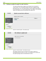
10.5
Web interface
Software update through the web interface
The web interface software update menu displays the concentrator’s
version history. The concentrator software can also be updated locally
through this menu, but it is recommended to use the update functionality in
Device Management, see Device Management User Manual. The metering
system can update several concentrators at the same time.
Figure 35. Software update ‒ SW Update page
Figure 36. Software update ‒ SW Update job page
SW Update job page shows the details of the software update job
downloaded from the system to the DC. This enables you to confirm that
the update package has been downloaded to the DC.
© Landis+Gyr
D000031888 en h – DC450 – User Manual
Maintenance and troubleshooting
49/54
11
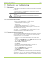
Maintenance and troubleshooting
11.1
Maintenance
The DC450 concentrator does not contain components that are maintained
by the user.
The device software can be updated either remotely from a metering
system or locally via web interface.
Warning!
Do not open the case when the device is connected to the electricity
network. Life hazard.
11.1.1 Concentrator software update
There are several update methods for DC450 software:
•
•
•
Update through the Gridstream system
Web interface
Update package download from HTTP or FTP server
The update process through the Gridstream system is described in the
Device Management User Manual.
See Chapter 10.5 Software update through the web interface, for more
information on updating DC450 through web interface.
11.1.2 Changing the communication module
The communication module must be disabled before it can be changed on
the concentrator. Removing the module before it is disabled can cause
malfunction of the DC and corrupted data.
1. Connect to the concentrator’s web interface either through LAN or
GPRS.
2. First select CONFIGURATION and then GSM in the Main Menu on the
left. The GSM CONFIG page is displayed.
3. Select Disabled and click Send.
4. Click Restart.
5. Remove the disabled module and replace it with a new one.
6. Activate the new module on the web interface.
•
•
Go to the GSM CONFIG page in web interface.
Select Static GPRS and click Send.
7. Click Restart.
If you use the same SIM card, the procedure is the same when replacing a
2G module with a 3G one. If you use a different SIM card with a different IP
address, the new IP address must be configured in the Gridstream system.
D000031888 en h – DC450 – User Manual
© Landis+Gyr
50/54
11.2
Maintenance and troubleshooting
Troubleshooting
11.2.1 No GSM/GPRS/UMTS connection to the DC450
If a DC450 GSM/GPRS/UMTS communication does not work, check the
following:
•
•
•
•
•
•
Is the GSM/UMTS signal strength sufficient?
Is the SIM card properly installed?
Is the SIM card’s PIN code request (GSM data only) switched off?
Is the GPRS configuration correct?
In case of a 3G module, are the required radio bands active?
Is the communication module operating?
See Chapter 5.2.5 Checking the signal strength and 5.2.6 Checking
GSM/GPRS/UMTS operation. If all of the above conditions are OK, check
with your operator that your service is correct and operational.
© Landis+Gyr
D000031888 en h – DC450 – User Manual
Decommissioning and disposal
12
51/54
Decommissioning and disposal
The components used to manufacture the device can, in the main, be
broken down into constituent parts and sent for suitable recycling or
disposal. When the product is removed from use, the whole product must
be sent to a professional electronic waste treatment process. The waste
treatment company must be accepted by the officials.
End processing of the product and recycling of its components must always
be carried out in accordance with the local laws and instructions given by
the officials of the country where the end processing and recycling are
done.
By request, Landis+Gyr will give more information about the environmental
influence of the product.
This product must not be disposed of in regular waste. Use a professional
electronic waste treatment process.
The following are general guidelines and should NOT take priority over
local disposal and environmental policies which should be adhered to
without compromise.
Component Parts
Disposal
Printed Circuit Boards
Electronic waste: disposal according to local
regulations.
Metal Components
Sorted and delivered to collective recycling
point.
Plastic Components
Sorted and delivered for re-granulation if at all
possible.
D000031888 en h – DC450 – User Manual
© Landis+Gyr
52/54
13
Terms and abbreviations
Terms and abbreviations
The following terms and abbreviations are used in this document.
© Landis+Gyr
Term
Description
2G Module
GSM/GPRS Module.
AMR
Automated Meter Reading. Refers to systems that are responsible
for handling tasks that require communication with metering devices,
for example reading of metering values. See HES.
APN
Access Point Name (APN) is the name of an access point for GPRS.
CSV
Comma Separated Value.
DC
Data Concentrator.
GPRS
General Packet Radio Service (GPRS) is a packet-based wireless
communication service that provides data rates from 56 up to 114
Kbps. It also offers a continuous connection to the Internet for mobile
phone and computer users.
Gridstream
AIM
Landis+Gyr’s Advanced Metering Management (AMM) system that
includes applications for Automated Meter Reading (AMR) and
Metering Data Management (MDM).
HES
Head-End System for automated meter reading. See AMR.
HTTP
Hypertext Transport Protocol (HTTP) is the communication protocol
used by the World Wide Web.
MDM
Metering Data Management. The metering database and metering
data processing system of Gridstream portfolio is also known as
Ware.
PIN
Personal Identification Number (PIN) is a code asked by the SIM
card to authenticate the user.
PLAN
Power Line Automation Network.
PLC
Power Line Communication.
SIM
Subscriber Identity Module (SIM) securely stores the servicesubscriber key (IMSI) used to identify a subscriber on mobile
telephony devices (such as computers) and mobile phones.
SMS
Short Message Service (SMS) is a pager-like service for GSM
mobile phones that allows the sending and receiving of alphanumeric
messages.
TCP/IP
Transmission Control Protocol/Internet Protocol (TCP/IP) is the suite
of protocols used to connect hosts on the Internet.
USB
Universal Serial Bus (USB) is a serial bus standard to interface
devices to a host computer.
WAN/LAN
Wide Area Network/Local Area Network.
Ware
See MDM.
D000031888 en h – DC450 – User Manual
Terms and abbreviations
D000031888 en h – DC450 – User Manual
53/54
© Landis+Gyr
Contact:
Landis+Gyr AG
Theilerstrasse 1
CH-6301 Zug
Switzerland
Phone: +41 41 935 6000
www.landisgyr.com