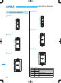
1
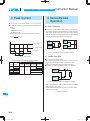
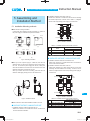
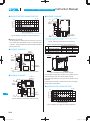
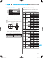
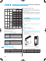
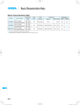
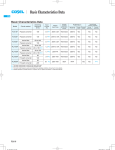
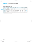
Basic Characteristics Data
Basic Characteristics Data
Model
KHEA30F
KHNA30F
KHEA60F
KHNA60F
Input
current
[A] *1
Flyback converter
50 - 200
0.55
250V 2.5A Thermistor
FR-4
Flyback converter
50 - 200
1.10
250V 3.15A Thermistor
0.95
250V 3.15A Thermistor
Active filter
20 - 500
KHNA90F
Flyback converter
50 - 200
KHEA120F
Active filter
60 - 550
KHNA120F LLC resonant converter
45 - 350
KHEA240F
60 - 550
Active filter
KHNA240F LLC resonant converter
45 - 350
KHEA480F
60 - 150
Active filter
KHNA480F LLC resonant converter
45 - 350
Series
operation
Parallel
operation
Yes
Yes
No
FR-4
Yes
Yes
No
FR-4
Yes
Yes
No
Material
Single Double
sided
sided
1.2
250V 5A
Thermistor
FR-4
Yes
Yes
No
2.3
250V 8A
SCR
FR-4
Yes
Yes
No
4.6
250V 15A
Relay
FR-4
Yes
Yes
No
*1 The value of input current is at ACIN 115V and 100%.
*2 Burst operation at light loading, frequency is change by use condition.
Please contact us about detail.
KH-14
Rated
input fuse
Series/Parallel
operation availability
PCB/Pattern
Switching
frequency
*2 [kHz]
KHEA90F
KH
Inrush
current
protection
circuit
Circuit method
AC-DC Power Supplies DIN Rail Type Instruction Manual
1
Terminal Blocks
KH-16
2
Functions
KH-18
2.1
Input Voltage Range
KH-18
2.2
Inrush Current Limiting
KH-18
2.3
Overcurrent Protection
KH-18
2.4
Peakcurrent Protection
KH-18
2.5
Overvoltage Protection
KH-18
2.6
Thermal Protection
KH-19
2.7
Output Ripple and Ripple Noise
KH-19
2.8
Remote ON/OFF
KH-19
2.9
Output Voltage Adjustment Range
KH-19
2.10
Isolation
KH-19
2.11
Signal Output
KH-19
3
Peak Current
KH-20
4
Series/Parallel Operation
KH-20
5
6
4.1
Series Operation
KH-20
4.2
Parallel Operation
KH-20
Assembling and Installation Method
KH-21
5.1
Installation Mounting methods
KH-21
5.2
Derating curve depend on input voltage
KH-22
5.3
Derating curve depend on ambient temperature
KH-22
5.4
Expected Life and Warranty
KH-25
5.5
Applicable Electric Cable
KH-28
5.6
Others
KH-28
Option
6.1
Outline of option
KH-28
KH-28
KH-15
KH
AC-DC Power Supplies DIN Rail Type
1 Terminal Blocks
Instruction Manual
¿ KHNA30F
¿ KHEA30F
4
5
6
7
4
5
1
6
7
3
2
3
2
1
¿ KHNA60F
¿ KHEA60F
4
5
6
7
4
5
3
2
6
7
1
3
2
1
¿ KHNA90F
¿ KHEA90F
4
5
6
7
3
4
5
2
1
6
7
KH
3
2
1
KH-16
Terminal
Number
1
2
3
4
5
6
7
Terminal
Name
PE
AC (N)
AC (L)
+VOUT
-VOUT
DC_OK
TRM
Function
Protective earth Terminal
Input Terminals
+Output Terminals
-Output Terminals
LED for output voltage confirmation
Adjustment of output voltage
Instruction Manual
AC-DC Power Supplies DIN Rail Type
¿ KHEA120F
¿ KHNA120F
5
6
4 5 6
7
0
8
7
0
8
å
9
å
9
1
1
2
¿ KHNA240F
3
¿ KHEA240F
2
5
3
6
7
0
8
å
4 5 6
9
7
0
8
å
9
1
¿ KHNA480F
1
2
5
2
6
7
3
8
¿ KHEA480F
9
0
å
4 5 6
7
1
8
9
0
å
1
3
2
3
Terminal
Number
1
2
3
4
5
6
7
8
9
0
å
Terminal
Name
PE
AC (N)
AC (L)
DC_OK
+VOUT
-VOUT
ALARM
DC_OK
TRM
+RC
-RC
2
3
KH
Function
Protective earth Terminal
Input Terminals
Output voltage confirmation(relay contact)
+Output Terminals
-Output Terminals
LED Alarm for lowered output voltage
LED for output voltage confirmation
Adjustment of output voltage
Remote ON/OFF Terminals
KH-17
AC-DC Power Supplies DIN Rail Type
2.3 Overcurrent Protection
2 Functions
¿ KHEA30F/60F/90F, KHNA30F/60F/90F
¡A overcurrent protection circuit is built-in and activated at 105% of
the rated current. A unit automatically recovers when a fault con-
2.1 Input Voltage Range
¡Input voltage range of the power supplies is from AC85V to
AC264V or DC (please see SPECIFICATIONS for details).
¡To comply with safety standards, input voltage range is AC100AC240V (50/60Hz).
¡If input value doesn’t fall within above range, a unit may not operate in accordance with specifications and/or start hunting or operate protection circuit or fail.
If you need to apply a square waveform input voltage, which is
commonly used in UPS and inverters, please contact us.
¡When the input voltage changes suddenly, the output voltage
accuracy might exceed the specification. Please contact us.
¿ KHEA30F/60F/90F, KHNA30F/60F/90F
¡Operation stop voltage is set at a lower value than of a standard
version (derating is needed).
-Use Conditions
KHEA30F,KHNA30F
KHEA60F,KHNA60F
KHEA90F,KHNA90F
Input
Instruction Manual
Output
10W
20W
30W
AC50V or DC70V
Duty 1s/30s
*Please avoid using continuously for more than 1 second under
above conditions. Doing so may cause a failure.
2.2 Inrush Current Limiting
¡An inrush current limiting circuit is built-in.
¡If you need to use a switch on the input side, please select one
that can withstand an input inrush current.
dition is removed. Please do not use a unit in short circuit and/or
under an overcurrent condition.
¡Intermittent Operation Mode (except KHEA/KHNA90F)
When the overcurrent protection circuit is activated and the output
voltage drops to a certain extent, the output becomes intermittent
so that the average current will also decrease.
¡Output Voltage Shutdown
If the output voltage drops according to the overcurrent protection
circuit operating continuously for about 0.5 second, the output
voltage may shut down. To recover the output voltage, remove a
condition that is causing an overcurrent, shut down the input voltage, wait more than 3 minutes and turn on the AC input again.
¿ KHEA120F/240F/480F, KHNA120F/240F/480F
¡An overcurrent protection circuit is built-in and activated at 101%
of the peak current. A unit automatically recovers when a fault
condition is removed. Please do not use a unit in short circuit
and/or under an overcurrent condition.
¡Intermittent Operation Mode
When the overcurrent protection circuit is activated and the outputvoltage drops to a certain extent, the output becomes intermittent so that the average current will also decrease.
2.4 Peakcurrent Protection
¿ KHEA120F/240F/480F, KHNA120F/240F/480F
¡Peakcurrent protection is built-in (refer to Instruction Manual 3 for
Peak loading).
If this function comes into effect, the output is shut down.
A few seconds later, A unit automatically recovers.
But if the overcurrent condition has not been released, the output
will stop again (intermittent Operation Mode).
¿ KHEA30F/60F/90F/120F,
KHNA30F/60F/90F/120F
*The recovery time varies depending on input voltage and load
condition.
¡Thermistor is used in the inrush current limiting circuit. When you
turn the power ON/OFF repeatedly within a short period of time,
2.5 Overvoltage Protection
please have enough intervals so that a power supply cools down
before being turned on.
¿ KHEA240F/480F, KHNA240F/480F
KH
¡Thyristor technique (KHEA/KHNA240F) and power relay technique (KHEA/KHNA480F) is used in the inrush current limiting
circuit.
¡When you turn the power ON/OFF repeatedly within a short period
of time, please have enough intervals so that the inrush current
limiting circuit becomes operative.
¡When the switch of the input is turned on, the primary inrush current and secondary inrush current will be generated.
¿ KHEA30F/60F/90F, KHNA30F/60F/90F
¡An overvoltage protection circuit is built-in. If the overvoltage protection circuit is activated, shut down the input voltage, wait more
than 3 minutes and turn on the AC input again to recover the output voltage. Recovery time varies depending on such factors as
input voltage value at the time of the operation.
¿ KHEA120F/240F/480F, KHNA120F/240F/480F
¡An overvoltage protection circuit is built-in.
A unit automatically recovers when the fault condition is removed.
Note :
Please avoid applying a voltage exceeding the rated voltage to an
output terminal. Doing so may cause a power supply to malfunction or fail. If you cannot avoid doing so, for example, if you need
to operate a motor, etc., please install an external diode on the
output terminal to protect the unit.
KH-18
AC-DC Power Supplies DIN Rail Type
2.6 Thermal Protection
R [W]=
¿ KHEA120F/240F/480F, KHNA120F/240F/480F
¡A thermal protection circuit is built-in.
The thermal protection circuit may be activated under the following conditions and shut down the output.
1When a temperature continue to exceed the values determined
by the derating curve.
2When a current exceeding the rated current is applied.
3When convection stops.
4When peak load is applied in conditions other than those shown
in Section 3.
A unit automatically recovers when the fault condition is removed.
Instruction Manual
Vcc-(1.1+RiX0.005)
0.005
¡Please wire carefully. If you wire wrongly, the internal components
of a unit may be damaged.
¡Remote ON/OFF circuits (+RC and -RC) are isolated from input,
output and PE.
¡Restart time is 750 ms max .
2.9 Output Voltage Adjustment Range
¡To increase an output voltage, turn a built-in potentiometer clockwise. To decrease the output voltage, turn it counterclockwise.
2.7 Output ripple and ripple noise
2.10 Isolation
¡Output ripple noise may be influenced by measurement environment, measuring method fig 2.1 is recommended.
¡When you run a Hi-Pot test as receiving inspection, gradually
increase the voltage to start. When you shut down, decrease the
voltage gradually by using a dial. Please avoid a Hi-Pot tester with
a timer because, when the timer is turned ON or OFF, it may gen-
+Vout
C1
erate a voltage a few times higher than the applied voltage.
C2 +
Load
2.11 Signal Output
-Vout
150mm
Functions of LED indicators and signal output (KHEA series)
Osiloscope/
Ripple noise meter
Bw:20MHz
¿ KHEA120F/240F/480F, KHNA120F/240F/480F
Differential probe
C1:Film capacitor 0.1mF
C2:Aluminum electrolytic capacitor 22 mF
¡Functions of LED indicators and signal output in the form of relay
contact are shown below. Checking the presence/absence of voltage at the output terminal of a power supply is possible.
Fig.2.1 Measuring method of Ripple and Ripple Noise
Table 2.2 Description of the signal output
2.8 Remote ON/OFF
¡You can reduce the standby power by Remote ON/OFF.
To do so, connect an external DC power supply and apply a volt-
Table 2.1 Remote ON/OFF Specifications
Negative
Between +RC and -RC
L level (0 to 0.5V) or open
H level (4.5 to 29.5V)
R*1
External Power
Souce
SW
+RC
*
Normal
ON
OFF
Short
Output is decreasing
OFF
ON
Open
*DC_OK signal (relay contact) is built in KHEA series. This circuit
is insulated from other circuits (input and output circuits).
age to a remote ON/OFF connector.
ON/OFF logic
Signal Output
DC_OK (LED: Green)
ALARM (LED: Red)
DC_OK (Relay Contact)
Output voltage
ON
OFF
Caution on signal outputs :
¡The timing of signals might be very depending on models, input
and load conditions. Please make sure enough evaluation.
Inside of a Power
Supply
Ri=2040 W
Input current
(20mA max)
KH
-RC
Fig.2.2 Example of use with remote ON/OFF
*1 If the output of an external power supply is within the range of
4.5 - 29.5V, you do not need a current limiting resistor R. If the
output exceeds 29.5V, however, please connect the current limiting resistor R.
To calculate a current limiting resistance value, please use the following equation.
KH-19
Instruction Manual
AC-DC Power Supplies DIN Rail Type
3 Peak Current
¿ KHEA120F/240F/480F, KHNA120F/240F/480F
¡The units can generate the peak current under the following conditions.
-t1[5sec
*Please use a maximum of Duty following shown in Table 3.1.
plies that are serially connected. Please make sure that no current
exceeding the rated current flows into a power supply.
X100 [%]
Power +
Supply -
[A]
Output current
Ip : Peak current
Iave : Average current
Load
Power +
Supply Power +
Supply -
Load
t1+t2
power supply with the lowest rated current among the power sup-
Load
-Duty=
4.1 Series Operation
¡You can use a power supply in series operation. The output current in series operation should be lower than the rated current of a
-Ip[Rated peak current
-Iave[Rated current
t1
4 Series/Parallel
Operation
Power +
Supply -
(a)
(b)
I : Load current
Fig.4.1 Examples of connecting in series operation
t2
4.2 Parallel Operation
Fig.3.1 Peak current
Table 3.1 Maximum Duty by the mounting orientation
Mounting
Input
orientation
Voltage
A
B
C
D
E
AC85 - 170V
AC170 - 264V
AC85 - 264V
AC85 - 264V
AC85 - 264V
AC85 - 264V
KHEA120F
KHNA120F
35%
Maximum Duty
KHEA240F KHEA480F-24 KHEA480F-48
KHNA240F KHNA480F-24 KHNA480F-48
20%
20%
15%
20%
35%
5%
¡There is no current balance function.
When operating in parallel, such as diode-OR, please use on the
output voltage was adjusted enough to balance the current.
Exceeds the rated output current, the output is shut down.
¡Redundancy operation is available by wiring as shown below.
I1
I3
Power +
Supply
-
20%
Load
t1
Power +
Supply
I2
-
Fig.4.2 Example of connecting in redundancy operation
Even a slight difference in output voltage can affect the balance
between the values of I1 and I2.
Please make sure that the value of l3 does not exceed the rated
current of a power supply.
l3 [ rated current value
KH
KH-20
AC-DC Power Supplies DIN Rail Type
Instruction Manual
2 Installation clearance at the side of the unit.
Please have clearance of at least 5mm side the unit to insulating
5 Assembling and
Installation Method
the internal components. However, refer to Table 5.1, if adjacent
device of the unit (including power supply) is a heat source.
Convection
2
5.1 Installation Mounting methods
1
25mm
or more
¡Below shows mounting orientation.
If install other then standard mounting orientation (A), please fix
the power supply for withstand the impact and vibration.
INPUT
OUTPUT
OUTPUT
INPUT
DIN rail
1
25mm
or more
Convection
Fig.5.3 Installation clearance
INPUT
OUTPUT
(A) Standard
(B)
Table 5.1 Installation clearance at the side of the unit.
(C)
No.
INPUT
OUTPUT
OUTPUT
INPUT
1
2
3
Model
KHEA30F, KHNA30F
KHEA60F, KHNA60F
KHEA90F, KHNA90F
Adjacent device of the unit
Non-heat source Heat source(*)
5mm or more 15mm or more
5mm or more 15mm or more
5mm or more 15mm or more
*Reference value when same power units are adjacent.
(D)
(E)
¿ KHEA120F/240F/480F, KHNA120F/240F/480F
Fig.5.1 Mounting orientation
¡When you mount a power supply on a DIN rail, have the area
marked A catch one side of the rail and push the unit to the direction of B. To remove the power supply from the rail, either push
down the area marked C or insert a tool such as driver to the area
1 Installation clearance at above and below the unit.
Please have clearance of at least 25mm above and below the
unit to avoid heat accumulation.
2 Installation clearance at the side of the unit.
Please have clearance of at least 15mm side the unit to avoid
marked D and pull the unit apart from the rail.
interfering with heat radiation from housing. However, refer to
When you couldn’t remove the unit easily, push down the area
Table 5.2, if adjacent device of the unit (including power supply) is
marked C while lightly pushing the unit to the direction of E.
a heat source.
1
C
Convection
2
25mm
or more
E
A
B
Convection
1
25mm
or more
KH
D
Fig.5.4 Installation clearance
Table 5.2 Installation clearance at the side of the unit.
Fig.5.2 Installation method
No.
¡Shown below the notes about installation clearance of a unit.
¿ KHEA30F/60F/90F, KHNA30F/60F/90F
1 Installation clearance at above and below the unit.
Please have clearance of at least 25mm above and below the
1
2
3
Model
KHEA120F, KHNA120F
KHEA240F, KHNA240F
KHEA480F, KHNA480F
Adjacent device of the unit
Non-heat source Heat source(*)
15mm or more
15mm or more
15mm or more 50mm or more
*Reference value when same power units are adjacent.
unit to avoid heat accumulation.
KH-21
AC-DC Power Supplies DIN Rail Type
(D), (E)
5.2 Derating curve depend on input voltage
¡Derating curve depend on input voltage.
Derating curve depend on input voltage is shown in Fig.5.5.
Vin=AC170V - 264V
40
30
20
0
- 30 - 20 - 10
100
0
10 20 30 40 50 60
Ambient Temperature [C]
¡Derating curve depend on input voltage.
Derating curve depend on input voltage is shown in Fig.5.6.
Load factor [%]
¿ KHEA480F, KHNA480F
(A)
80
60
50
4035
30
20
Vin=AC85V - 170V *
0
-30 -20 -10
0
[%]
10 20 30 40 50 55 60
Ambient Temperature [C]
70
80
* Derating curve depend on input voltage is required.
100
Fig.5.9 Derating curve depend on ambient temperature
80
(E)
85
100
[AC V]
Fig.5.6 Derating curve depend on input voltage
5.3 Derating curve depend on ambient temperature
(B)
(A)
80
60
¡In the hatched area,the specification of Ripple,Ripple Noise is different from other area.
¡Derating Curve (Convection)
0
(A)
Load factor [%]
(B)
80
(B), (D), (E)
(A)
80
60
10 20 30 40 45 50 60
Ambient Temperature [C]
70
80
* Derating curve depend on input voltage is required.
Fig.5.7 Derating curve depend on ambient temperature
Vin=AC85V - 170V *
40
30
20
0
-30 -20 -10
0
70
¿ KHEA90F, KHNA90F
(C)
Vin=AC85V - 170V *
40
30
20
10 20 30 40 45 50 55 60
Ambient Temperature [C]
100
100
80
70
60
0
Fig.5.10 Derating curve depend on ambient temperature
¿ KHEA30F, KHNA30F
(C), (D), (E)
Vin=AC170V - 264V
45
40
30
20
- 30 - 20 - 10
¡The operative ambient temperature as different by input voltage.
Derating curve is shown below.
0
-30 -20 -10
(C), (D)
100
Load factor [%]
Load Factor
(C)
100
[AC V]
Fig.5.5 Derating curve depend on input voltage
Load factor [%]
80
¿ KHEA60F, KHNA60F
(B), (D), (E)
KH-22
70
Fig.5.8 Derating curve depend on ambient temperature
80
85 90
KH
(A)
80
70
60
[%]
Load Factor
(B), (C)
100
Load factor [%]
¿ KHEA30F/60F/90F, KHNA30F/60F/90F
Instruction Manual
0
10 20 30 40 45 50 55 60
Ambient Temperature [C]
70
80
* Derating curve depend on input voltage is required.
Fig.5.11 Derating curve depend on ambient temperature
AC-DC Power Supplies DIN Rail Type
(B), (C)
(A)
(C), (D), (E)
100
100
80
80
75
60
50
40
30
20
Load factor [%]
Load factor [%]
(D), (E)
60
40
30
20
0
-3 0 -2 0 - 10
Vin=AC170V - 264V
0
10 20 30 40 50 55 60 65 70
Ambient Temperature [C]
0 10 20 30 40 50
Ambient Temperature [C]
60
70
80
Fig.5.16 Derating curve depend on ambient temperature
(C), (D), (E)
(B)
(B)
(A)
Load factor [%]
Vin=AC85V - 170V
0 10 20 30 40 50
Ambient Temperature [C]
60
70
(D), (E)
(C)
(A)
100
100
Load factor [%]
(A)
¿ KHEA480F, KHNA480F
¿ KHEA120F, KHNA120F
0
-30 -20 -10
(B)
Vin=AC170V - 264V
0
-30 -20 -10
80
Fig.5.12 Derating curve depend on ambient temperature
80
75
60
50
40
30
20
Instruction Manual
80
60
50
40
30
20
Vin=AC85V - 170V *
0
-30 -20 -10
80
0
10 20 2530 40 50 60
Ambient Temperature [C]
70
80
* Derating curve depend on input voltage is required.
Fig.5.13 Derating curve depend on ambient temperature
Fig.5.17 Derating curve depend on ambient temperature
(C), (D), (E)
(B)
(A)
(B)
80
75
60
40
30
20
0
-30 -20 -10
(D), (E)
(C)
(A)
100
Load factor [%]
Load factor [%]
100
Vin=AC170V - 264V
0 10 20 30 40 50
Ambient Temperature [C]
60
70
80
80
60
50
40
30
20
0
-30 -20 -10
Vin=AC170V - 264V
0
10 20 30 40 50 60
Ambient Temperature [C]
70
80
Fig.5.14 Derating curve depend on ambient temperature
Fig.5.18 Derating curve depend on ambient temperature
¡Ambient temperature indicates the temperature of the inlet of the
air.
¿ KHEA240F, KHNA240F
(C), (D), (E)
(B)
(A)
Load factor [%]
100
80
60
50
40
30
20
0
-30 -20 -10
Vin=AC85V - 170V
0 10 20 30 40 50
Ambient Temperature [C]
60
70
KH
80
Fig.5.15 Derating curve depend on ambient temperature
Airflow
Ambient temperature
measurement point
Fig.5.19 Ambient temperature measurement point
KH-23
AC-DC Power Supplies DIN Rail Type
¿ KHEA30F/60F/90F, KHNA30F/60F/90F
Instruction Manual
¿ KHEA90F, KHNA90F
(A) - (E)
Load factor [%]
100
TB2
80
60
POINT B *
(C515)
Vin=AC85V - 264V *
40
30
20
Forced air (0.5m 3 /min)
0
-30 -20 -10
0
10 20 30 40 50 60
Ambient Temperature [C]
70
80
* Derating curve depend on input voltage is required.
¡Temperature of Forced air
Use the temperature measurement point as shown in Fig.5.21 to
*Please be careful of electric shock or earth leakage in case of temperature measurement,
because POINT A and POINT B is live potential.
Fig.5.23 Temperature measurement point (Forced air)
5.23. Please use at the temperature dose not exceed the values
Table 5.3 Specified temperature of the measurement point
in Table 5.3. Please also make sure that the ambient temperature
does not exceed 70C.
¿ KHEA30F, KHNA30F
POINT C
(T201)
POINT A *
(C106)
TB1
Fig.5.20 Derating curve depend on ambient temperature
No.
Model
1
2
3
KHEA30F, KHNA30F
KHEA60F, KHNA60F
KHEA90F, KHNA90F
OUTPUT
TB2
Temperature measurement point
Point A
Point B
Point C
80C
80C
105C
80C
80C
105C
80C
80C
CASE
4- JOINT PART
POINT B
(C515)
POINT A
(C106)
TB1
INPUT
Fig.5.21 Temperature measurement point (Forced air)
¿ KHEA60F, KHNA60F
CHASSIS
Fig.5.24 Installation removing chassis and case
Thermocouple for temperature checking must be added into temperature measuring point after removing chassis and case.
POINT C
(T201)
Then assembling chassis and case again, the temperature can be
measured.
TB2
Chassis and case are fixed in 4 parts which are shown in the figure.
Please contact us about detail.
POINT B
(C516)
¿ KHEA120F/240F, KHNA120F/240F
(A) - (E)
KH
POINT A
(C107)
TB1
Fig.5.22 Temperature measurement point (Forced air)
Load factor [%]
100
80
60
Vin=AC85V - 264V
40
30
20
0
-30 -20 -10
Forced air
0
10
20
30
40
50
60
70
80
Ambient Temperature [C]
Fig.5.25 Derating curve depend on ambient temperature
KH-24
AC-DC Power Supplies DIN Rail Type
¿ KHEA480F, KHNA480F
(A) - (E)
Load factor [%]
100
5.4 Expectancy life and warranty
Please note derating curve depend on input voltage is required.
¡Expectancy Life.
80
60
Vin=AC85V - 264V *
40
30
20
0
-30 -20 -10
Instruction Manual
Table 5.5 Expectancy Life (KHEA30F, KHNA30F)
Forced air
0
10
20
30
40
50
60
70
Mounting
Cooling
Input
Average ambient
method
method
voltage
temperature (year)
80
Ambient Temperature [C]
* Derating curve depend on input voltage is required.
AC85 - 170V
A
Convection
AC170 - 264V
Fig.5.26 Derating curve depend on ambient temperature
¡Temperature of Forced air
Use the temperature measurement point as shown in Fig 5.27.
AC85 - 170V
B
Convection
AC170 - 264V
Please use at the temperature does not exceed the values in
AC85 - 170V
Table 5.4.
Please also make sure that the ambient temperature does not ex-
C
Convection
AC170 - 264V
ceed 70C.
Temperature
measureing point
Airflow
AC85 - 170V
D
Convection
AC170 - 264V
AC85 - 170V
E
Convection
AC170 - 264V
A,B,C,D
Forced air
and E
Ta = 50C or less
Ta = 60C
Ta = 50C or less
Ta = 60C
Ta = 40C or less
Ta = 50C
Ta = 50C or less
Ta = 60C
Ta = 35C or less
Ta = 45C
Ta = 50C or less
Ta = 60C
Ta = 35C or less
Ta = 45C
Ta = 50C or less
Ta = 60C
Ta = 35C or less
Ta = 45C
Ta = 50C or less
Ta = 60C
AC85 - 264V Ta = 70C
Expectancy Life
Load factor
Load factor
Io[75%
10years
6years
10years
6years
10years
10years
10years
6years
10years
10years
10years
5years
10years
10years
10years
5years
10years
10years
10years
5years
75%<Io[100%
7years
3years
9years
4years
10years
6years
9years
4years
10years
7years
6years
3years
10years
6years
7years
3years
10years
6years
7years
3years
5years
3years
Airflow
Table 5.6 Expectancy Life (KHEA60F, KHNA60F)
Fig.5.27 Temperature measurement point (Forced air)
Mounting
Cooling
Input
Average ambient
method
method
voltage
temperature (year)
Table 5.4 Specified temperature of the measurement point
No.
1
2
3
Model
temperature measurement point
KHEA120F, KHNA120F
75C
KHEA240F, KHNA240F
80C
KHEA480F, KHNA480F
85C
AC85 - 170V
A
Convection
AC170 - 264V
AC85 - 170V
B
Convection
AC170 - 264V
AC85 - 170V
C
Convection
AC170 - 264V
AC85 - 170V
D
Convection
AC170 - 264V
AC85 - 170V
E
Convection
AC170 - 264V
A,B,C,D
and E
Forced air
Ta = 45C or less
Ta = 55C
Ta = 45C or less
Ta = 55C
Ta = 30C or less
Ta = 40C
Ta = 45C or less
Ta = 55C
Ta = 40C or less
Ta = 50C
Ta = 40C or less
Ta = 50C
Ta = 30C or less
Ta = 40C
Ta = 40C or less
Ta = 50C
Ta = 30C or less
Ta = 40C
Ta = 35C or less
Ta = 45C
AC85 - 264V Ta = 70C
Expectancy Life
Load factor
Load factor
Io[75%
10years
5years
10years
9years
10years
9years
9years
5years
10years
7years
10years
8years
10years
8years
10years
6years
10years
9years
10years
10years
75%<Io[100%
5years
3years
10years
6years
7years
3years
7years
3years
6years
3years
10years
5years
5years
2years
8years
4years
6years
3years
10years
7years
5years
3years
KH-25
KH
AC-DC Power Supplies DIN Rail Type
Table 5.7 Expectancy Life (KHEA90F, KHNA90F)
Mounting
Cooling
Input
Average ambient
method
method
voltage
temperature (year)
A
Convection
AC85 - 170V
AC170 - 264V
AC85 - 170V
B
Convection
AC170 - 264V
AC85 - 170V
C
Convection
AC170 - 264V
AC85 - 170V
D
Convection
AC170 - 264V
AC85 - 170V
E
Convection
AC170 - 264V
A,B,C,D
and E
Forced air
Ta = 45C or less
Ta = 55C
Ta = 45C or less
Ta = 55C
Ta = 35C or less
Ta = 45C
Ta = 30C or less
Ta = 40C
Ta = 30C or less
Ta = 40C
Ta = 30C or less
Ta = 40C
Ta = 35C or less
Ta = 45C
Ta = 30C or less
Ta = 40C
Ta = 35C or less
Ta = 45C
Ta = 30C or less
Ta = 40C
AC85 - 264V Ta = 70C
Expectancy Life
Load factor
Load factor
Io[75%
10years
7years
10years
10years
10years
8years
10years
10years
10years
10years
10years
10years
10years
10years
10years
10years
10years
10years
10years
10years
75%<Io[100%
8years
4years
10years
7years
10years
7years
10years
10years
10years
8years
10years
10years
8years
4years
10years
10years
10years
5years
10years
10years
5years
3years
Table 5.8 Expectancy Life (KHEA120F, KHNA120F)
Mounting
Cooling
Input
Average ambient
method
method
voltage
temperature (year)
AC85 - 170V
A
Convection
AC170 - 264V
AC85 - 170V
B
Convection
AC170 - 264V
AC85 - 170V
C
Convection
AC170 - 264V
AC85 - 170V
D
Convection
AC170 - 264V
AC85 - 170V
E
Convection
AC170 - 264V
A,B,C,D
and E
KH
KH-26
Forced air
Ta = 50C or less
Ta = 60C
Ta = 50C or less
Ta = 60C
Ta = 40C or less
Ta = 50C
Ta = 40C or less
Ta = 50C
Ta = 20C or less
Ta = 30C
Ta = 40C or less
Ta = 50C
Ta = 20C or less
Ta = 30C
Ta = 40C or less
Ta = 50C
Ta = 20C or less
Ta = 30C
Ta = 40C or less
Ta = 50C
AC85 - 264V Ta = 70C
Table 5.9 Expectancy Life (KHEA240F, KHNA240F)
Mounting
Cooling
Input
Average ambient
method
method
voltage
temperature (year)
A
Convection
AC85 - 170V
AC170 - 264V
AC85 - 170V
B
Convection
AC170 - 264V
AC85 - 170V
C
Convection
AC170 - 264V
AC85 - 170V
D and E
Convection
AC170 - 264V
A,B,C,D
and E
Forced air
Load factor
Io[75%
10years
8years
10years
5years
10years
8years
10years
8years
10years
10years
10years
5years
10years
10years
10years
5years
10years
10years
10years
5years
75%<Io[100%
8years
3years
6years
4years
10years
5years
10years
5years
10years
10years
10years
3years
10years
8years
8years
3years
10years
8years
10years
3years
5years
3years
Ta = 40C or less
Ta = 50C
Ta = 50C or less
Ta = 60C
Ta = 30C or less
Ta = 40C
Ta = 40C or less
Ta = 50C
Ta = 20C or less
Ta = 30C
Ta = 40C or less
Ta = 50C
Ta = 20C or less
Ta = 30C
Ta = 40C or less
Ta = 50C
AC85 - 264V Ta = 70C
Expectancy Life
Load factor
Load factor
Io[75%
10years
5years
10years
5years
10years
10years
10years
10years
10years
10years
10years
6years
10years
10years
10years
5years
75%<Io[100%
6years
3years
6years
3years
10years
8years
10years
6years
10years
8years
8years
3years
10years
5years
6years
3years
5years
3years
Table 5.10 Expectancy Life (KHEA480F, KHNA480F)
Mounting
Cooling
Input
Average ambient
method
method
voltage
temperature (year)
Expectancy Life
Load factor
Instruction Manual
A
Convection
B
Convection
C
Convection
D
Convection
E
Convection
A,B,C,D
and E
Forced air
Ta = 40C or less
AC85 - 170V Ta = 45C
Ta = 50C
Ta = 50C or less
AC170 - 264V Ta = 55C
Ta = 60C
Ta = 10C or less
AC85 - 170V
Ta = 20C
Ta = 20C or less
AC170 - 264V
Ta = 30C
Ta = 15C or less
AC85 - 170V
Ta = 25C
Ta = 30C or less
AC170 - 264V
Ta = 40C
Ta = 10C or less
AC85 - 170V
Ta = 20C
Ta = 20C or less
AC170 - 264V
Ta = 30C
Ta = 10C or less
AC85 - 170V
Ta = 20C
Ta = 20C or less
AC170 - 264V
Ta = 30C
AC85 - 264V Ta = 70C
Expectancy Life
Load factor
Load factor
Io[75%
10years
7years
5years
8years
5years
4years
10years
10years
10years
10years
10years
10years
10years
8years
10years
10years
10years
10years
10years
8years
10years
10years
75%<Io[100%
4years
3years
2years
4years
3years
2years
10years
10years
10years
10years
10years
5years
7years
3years
10years
5years
10years
5years
7years
3years
7years
3years
5years
3years
AC-DC Power Supplies DIN Rail Type
Instruction Manual
¡Warranty
Table 5.13 Warranty (KHEA90F, KHNA90F)
Table 5.11 Warranty (KHEA30F, KHNA30F)
Mounting
Cooling
Input
Average ambient
method
method
voltage
temperature (year)
A
Convection
AC85 - 170V
AC170 - 264V
AC85 - 170V
B
Convection
AC170 - 264V
AC85 - 170V
C
Convection
AC170 - 264V
AC85 - 170V
D and E
Convection
AC170 - 264V
A,B,C,D
and E
Forced air
Ta = 50C or less
Ta = 60C
Ta = 50C or less
Ta = 60C
Ta = 40C or less
Ta = 50C
Ta = 50C or less
Ta = 60C
Ta = 35C or less
Ta = 45C
Ta = 50C or less
Ta = 60C
Ta = 35C or less
Ta = 45C
Ta = 50C or less
Ta = 60C
AC85 - 264V Ta = 70C
Warranty term
Load factor
Load factor
Io[75%
5years
5years
5years
5years
5years
5years
5years
5years
5years
5years
5years
5years
5years
5years
5years
5years
75%<Io[100%
5years
3years
5years
3years
5years
3years
5years
3years
5years
5years
5years
3years
5years
3years
5years
3years
5years
3years
Mounting
Cooling
Input
Average ambient
method
method
voltage
temperature (year)
A
Convection
AC85 - 170V
AC170 - 264V
AC85 - 170V
B
AC170 - 264V
AC85 - 170V
C
Cooling
Input
Average ambient
method
method
voltage
temperature (year)
A
Convection
AC85 - 170V
AC170 - 264V
AC85 - 170V
B
Convection
AC170 - 264V
AC85 - 170V
C
Convection
AC170 - 264V
AC85 - 170V
D
Convection
AC170 - 264V
AC85 - 170V
E
Convection
AC170 - 264V
A,B,C,D
and E
Forced air
Ta = 45C or less
Ta = 55C
Ta = 45C or less
Ta = 55C
Ta = 30C or less
Ta = 40C
Ta = 45C or less
Ta = 55C
Ta = 40C or less
Ta = 50C
Ta = 40C or less
Ta = 50C
Ta = 30C or less
Ta = 40C
Ta = 40C or less
Ta = 50C
Ta = 30C or less
Ta = 40C
Ta = 35C or less
Ta = 45C
AC85 - 264V Ta = 70C
Convection
AC170 - 264V
AC85 - 170V
D and E
Convection
AC170 - 264V
A,B,C,D
and E
Forced air
AC85 - 264V Ta = 70C
Load factor
Io[75%
5years
5years
5years
5years
5years
5years
5years
5years
5years
5years
5years
5years
5years
5years
5years
5years
75%<Io[100%
5years
3years
5years
5years
5years
5years
5years
5years
5years
5years
5years
5years
5years
3years
5years
5years
5years
3years
Table 5.14 Warranty (KHEA120F, KHNA120F)
Table 5.12 Warranty (KHEA60F, KHNA60F)
Mounting
Convection
Ta = 45C or less
Ta = 55C
Ta = 45C or less
Ta = 55C
Ta = 35C or less
Ta = 45C
Ta = 30C or less
Ta = 40C
Ta = 30C or less
Ta = 40C
Ta = 30C or less
Ta = 40C
Ta = 35C or less
Ta = 45C
Ta = 30C or less
Ta = 40C
Warranty term
Load factor
Warranty term
Load factor
Load factor
Io[75%
5years
5years
5years
5years
5years
5years
5years
5years
5years
5years
5years
5years
5years
5years
5years
5years
5years
5years
5years
5years
75%<Io[100%
3years
3years
5years
3years
5years
3years
3years
3years
3years
3years
5years
3years
3years
2years
5years
3years
3years
3years
5years
3years
5years
3years
Mounting
Cooling
Input
Average ambient
method
method
voltage
temperature (year)
A
Convection
AC85 - 170V
AC170 - 264V
AC85 - 170V
B
Convection
AC170 - 264V
AC85 - 170V
C,D and E Convection
AC170 - 264V
A,B,C,D
and E
Forced air
Ta = 50C or less
Ta = 60C
Ta = 50C or less
Ta = 60C
Ta = 40C or less
Ta = 50C
Ta = 40C or less
Ta = 50C
Ta = 20C or less
Ta = 30C
Ta = 40C or less
Ta = 50C
AC85 - 264V Ta = 70C
Warranty term
Load factor
Load factor
Io[75%
5years
5years
5years
5years
5years
5years
5years
5years
5years
5years
5years
5years
75%<Io[100%
5years
3years
5years
4years
5years
5years
5years
5years
5years
5years
5years
3years
5years
3years
Table 5.15 Warranty (KHEA240F, KHNA240F)
Mounting
Cooling
Input
Average ambient
method
method
voltage
temperature (year)
A
Convection
AC85 - 170V
AC170 - 264V
AC85 - 170V
B
Convection
AC170 - 264V
AC85 - 170V
C,D and E Convection
AC170 - 264V
A,B,C,D
and E
Forced air
Ta = 40C or less
Ta = 50C
Ta = 50C or less
Ta = 60C
Ta = 30C or less
Ta = 40C
Ta = 40C or less
Ta = 50C
Ta = 20C or less
Ta = 30C
Ta = 40C or less
Ta = 50C
AC85 - 264V Ta = 70C
Warranty term
Load factor
Load factor
Io[75%
5years
5years
5years
5years
5years
5years
5years
5years
5years
5years
5years
5years
75%<Io[100%
5years
3years
5years
3years
5years
5years
5years
5years
5years
5years
5years
3years
5years
3years
KH-27
KH
AC-DC Power Supplies DIN Rail Type
Table 5.16 Warranty (KHEA480F, KHNA480F)
Mounting
Cooling
Input
Average ambient
method
method
voltage
temperature (year)
A
Convection
B
Convection
C
Convection
D
Convection
E
A,B,C,D
and E
Convection
Forced air
Ta = 40C or less
AC85 - 170V Ta = 45C
Ta = 50C
Ta = 50C or less
AC170 - 264V Ta = 55C
Ta = 60C
Ta = 10C or less
AC85 - 170V
Ta = 20C
Ta = 20C or less
AC170 - 264V
Ta = 30C
Ta = 15C or less
AC85 - 170V
Ta = 25C
Ta = 30C or less
AC170 - 264V
Ta = 40C
Ta = 10C or less
AC85 - 170V
Ta = 20C
Ta = 20C or less
AC170 - 264V
Ta = 30C
Ta = 10C or less
AC85 - 170V
Ta = 20C
Ta = 20C or less
AC170 - 264V
Ta = 30C
AC85 - 264V Ta = 70C
Instruction Manual
5.6 Applicable Electric Cable
Warranty term
Load factor
Load factor
Io[75%
5years
5years
4years
5years
5years
4years
5years
5years
5years
5years
5years
5years
5years
5years
5years
5years
5years
5years
5years
5years
5years
5years
75%<Io[100%
4years
3years
2years
4years
3years
2years
5years
5years
5years
5years
5years
5years
5years
3years
5years
5years
5years
5years
5years
3years
5years
3years
5years
3years
¡While turning on the electricity, and for a while after turning off,
please don’t touch the inside of a power supply because there are
some hot parts in that.
¡When a mass capacitor is connected with the output terminal
(load side), the output might become the stop or an unstable operation. Please contact us for details when you connect the capacitor.
6 Option
6.1 Outline of option
¿ -C
-Option -C units have coated internal PCB for better moisture
resistance.
¿ -E
(KHEA90F, KHNA90F)
-Option -E units acquires NEC Class2.
5.5 Applicable Electric Cable
¡Input terminals, Output terminals
¿ KHEA30F/60F/90F/120F/240F
Table 5.17 Applicable Wire
Solid wire
Stranded wire
Sheath strip length
Input terminals
Output terminals
Diameter 0.5 mm to 2.6 mm (AWG.24 to AWG.10)
0.2mm2 to 5.2mm2 (AWG.24 to AWG.10)
¿ -N2
(KHEA120F/240F/480F, KHNA120F/240F/480F)
-Option -N2 units have attachment with screw mounting instead
of DIN rail mounting.
Mounting holes pitch are shown in Table 6.1.
4-f4.5
Conductor diameter more than 0.18mm
8mm
¿ KHEA480F
Solid wire
Stranded wire
Sheath strip length
B
Table 5.18 Applicable Wire
Input terminals
Output terminals
Diameter 0.8 mm to 2.6 mm (AWG.20 to AWG.10)
0.5mm2 to 5.2mm2 (AWG.20 to AWG.10)
Conductor diameter more than 0.18mm
8mm
A
¡RC terminals
¿ KHEA120F/240F/480F,
KH
KHNA120F/240F/480F
Fig.6.1 Image of option -N2
Table 5.19 Applicable Wire
RC terminals
Solid wire
Diameter 0.5 mm to 1.3 mm (AWG.24 to AWG.16)
Stranded wire
0.2 mm2 to 1.5 mm2 (AWG.24 to AWG.16)
Sheath strip length
8mm
KH-28
Fig.6.2 Mounting place
(screw holes)
Table 6.1 Mounting holes pitch
No.
1
2
3
Model
KHEA120F, KHNA120F
KHEA240F, KHNA240F
KHEA480F, KHNA480F
A
23mm
34mm
54mm
B
133mm
133mm
133mm