1
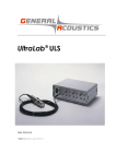
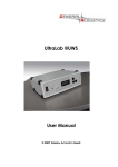
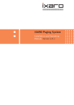
UltraLab®
ULS Advanced
User Manual
©
2005 GENERAL ACOUSTICS
UltraLab® ULS Advanced - User Manual
User notes:
Seite 2
UltraLab® ULS Advanced - User Manual
CONTENTS
1
General ________________________________________________________________________________________ 4
1.1
2
3
4
Safety instructions ___________________________________________________________________________ 4
Introduction ____________________________________________________________________________________ 6
2.1
Overview___________________________________________________________________________________ 6
2.2
System components __________________________________________________________________________ 7
2.3
Sensor characteristics ________________________________________________________________________ 7
Measurement setup_______________________________________________________________________________ 8
3.1
Compensation using a reference measurement ___________________________________________________ 9
3.2
Data telegram and trigger ___________________________________________________________________ 10
LAN configuration ______________________________________________________________________________ 12
4.1
General ___________________________________________________________________________________ 12
4.2
Moxa interface-converter____________________________________________________________________ 12
4.3
Software installation ________________________________________________________________________ 12
4.4
Configuring the interface ____________________________________________________________________ 12
4.4.1
Preparation_____________________________________________________________________________ 12
4.4.2
Changing the settings ____________________________________________________________________ 13
4.4.3
Search of a Moxa module _________________________________________________________________ 14
4.4.4
Parameter readout _______________________________________________________________________ 15
4.4.5
Configuration___________________________________________________________________________ 16
4.4.6
Network _______________________________________________________________________________ 17
4.4.7
Serial _________________________________________________________________________________ 18
4.4.8
Operation Mode_________________________________________________________________________ 19
4.4.9
Real COM Mode ________________________________________________________________________ 20
4.5
Install a virtual COM Port ___________________________________________________________________ 21
4.5.1
COM Mapping _________________________________________________________________________ 21
4.5.2
Assuming and establishing a COM Port ______________________________________________________ 24
5
Warranty statement _____________________________________________________________________________ 25
6
CE conformity statement _________________________________________________________________________ 26
7
Technical specifications __________________________________________________________________________ 26
Seite 3
UltraLab® ULS Advanced - User Manual
1
GENERAL
1.1 Safety instructions
For your own safety and for the safe operation of the system, please read the following instructions
carefully PRIOR to operating the system for the first time.
The UltraLab® ULS Advanced laboratory instrument, as well as the associated ultrasound sensors,
represent state-of-the-art technology and comply with the latest safety regulations.
The manufacturer has made every effort to guarantee safe operation. The user must ensure that the
instrument is set up and installed in such a way that its safe usage is not impaired.
The instruments are factory tested and were delivered in a safe operational condition.
This User Manual contains information and warnings, which must be observed by the user under all
circumstances to ensure safe operation of the instruments.
• The instrument may only be put into operation by authorised persons and only operated by trained
personnel. All users working with this instrument must read the User Manual prior to any operation.
• The user may only perform the repair and maintenance work described. Only the specified parts are to
be used.
Servicing work may only be carried out by authorised service technicians from GENERAL ACOUSTICS.
• All instruments and additional devices used for this purpose must be properly earthed.
• The earth leads must not be interrupted at any point.
• The UltraLab® ULS Advanced laboratory instrument may only be operated within the specified
temperature range of -20 to +70°C. Otherwise measurement inaccuracies and instrument faults or
defects may occur.
The temperature stability of connection cables must match the operating temperature of the
measurement system.
• The sensor should only be connected to the instrument when it is switched off.
• The sensors are to be treated with care and are only to be screwed in hand-tight; otherwise there is the
risk of damage. Sufficient leverage is obtained from the sensor casing itself.
• Avoid electrostatic discharges.
• The UltraLab® ULS Advanced instrument must not come into contact with liquids.
• Never operate the instrument at sites where water may get into the instrument.
• Also take care that the instrument is always operated above the water line of experimental reservoirs.
Protect the instrument against falling into water.
• Isolate all system devices from the mains before undertaking cleaning. Ensure there is no current. Do
not use aggressive cleaning chemicals, liquid cleaners or sprays; only use a damp cloth. Never bring
this or any other cloth into contact with parts of the system that will subsequently conduct electricity.
Seite 4
UltraLab® ULS Advanced - User Manual
• Never attempt to open instruments with objects or to insert objects into an instrument. The voltages
existing in the instruments can lead to short-circuits and electric shocks.
• Ensure adequate ventilation when operating the UltraLab® ULS Advanced. As the instrument has low
power consumption, it requires no additional ventilation under normal conditions. However, the
instrument should never be placed on a source of heat (computer monitors, radiators …).
Only operate the UltraLab® ULS Advanced at the intended mains voltage of 230 VAC (optionally 110
VAC).
• For safety reasons, the UltraLab® ULS Advanced is provided with a sealed appliance plug with earth
contact for its mains power. In this context, only appliance cables and plugs with earth contacts may
be used. Operation of the system is prohibited if you do not have this option. Never use an extension
cable without an earth contact.
• The instrument is protected from mains voltage by a blowout fuse in the appliance plug. A fine-wire
fast-blow fuse (G fuse 5 x 20 mm) compliant with IEC with a nominal value of 0.8(f) A is to be used as a
replacement. Only the specified values may be used. Higher tripping values or bridging of fuses is not
permissible. If the fuse repeatedly blows, the Service Department of GENERAL ACOUSTICS should be
informed, as the cause would need to be resolved.
• We recommend protecting the circuit with FI protective switches to ensure safe operation of your
complete system.
• Take care that power cables are not worn, abraded or otherwise defective. When routing connecting
cables, make certain that the cables do not represent an obstacle or risk of tripping.
• When using extension cables, the total nominal current of all the devices connected must not exceed
the allowable maximum current of the cable. The current ratings of all devices connected to a single
plug should never exceed 15 A, unless the plug is specifically designed for this purpose. If you are
unsure what type of mains power exists in your premises, ask your Safety Officer or an authorised
electrician.
It is imperative to isolate instruments from the mains in the following cases:
• If power cables or plugs are worn or damaged.
• If water or any other liquid has found its way into one of the instruments.
• If the instrument is not working correctly despite following the specified operating instructions.
• If one of the instruments has fallen down or the chassis is damaged.
• If the instrument shows any noticeable departure from normal operation.
• If the sensor connections have become wet.
With the exception of the actions explicitly specified in the manual, you should never attempt your own
repairs on devices belonging to the UltraLab® ULS Advanced system. Besides the resulting revocation of
warranty coverage, you also risk an electric shock or other injury from the components. All
maintenance work, unless explicitly described in the manual, should only be carried out by GENERAL
ACOUSTICS.
Seite 5
UltraLab® ULS Advanced - User Manual
2
INTRODUCTION
2.1 Overview
Ultrasound measurement of distances in laboratory measurement technology has become increasingly
established in recent years. The advantages gained are quite clear: particularly in small-scale
experimental set-ups, it is imperative to avoid any mechanical intervention that may affect the
experiment, but at the same time, parameters must be measured and evaluated. This not only applies
to laboratory operation and water. As the distance to an object is measured by sound propagation
time measurement, and not by intensity measurement, as is the case in optical methods, ultrasound
sensors have excellent background suppression. Almost all materials that reflect sound are reliably
detected, irrespective of their colour. Even transparent materials and thin foils present no problems for
our ultrasound sensors. As a result of their high sensitivity, our sensors are also predestined for the
detection of liquid surfaces. The sensors measure in dusty air as well as through fine fog. Even thin
deposition on the sensor membrane does not impair the sensor function. These characteristics,
combined with extremely slender sound cones (with practically no side lobes), make for completely
new laboratory applications.
The easy-to-use UltraLab® ULS Advanced laboratory instrument excels as a consequence of the diverse
functions implemented, making it suitable for use in complex measurement tasks without having to set a
series of parameters. The measurement object can be, for example, the water surface as a level or the
moving water surface as a wave. This is where the temporally highly resolved distance measurement
comes into its own. A complex measurement algorithm ensures high measurement accuracy and
resolution, as well as a high degree of data confidence.
The UltraLab® ULS Advanced is dedicated for sound propagation time measurement of very fast moving
waves. This device has four independent channels, each one is equipped with up to three sensors of the
type USS12-HF. The first (1.1, 2.1, 3.1 and 4.1) of these three sensors - belonging to one measurement unit
– are emitting the acoustic ping down to the water surface, whereas the reflected incoming signal can
be detected by all of the three independently.
Due to high repetition rate of 100 Hz, every measurement unit detects high dynamic processes in an
impressive resolution of 0.36 mm. Thanks to the application of a special reference sensor all fluctuations
of the sound velocity will be compensated internally. That means, the data obtained from the
measurement device are independent of all the sound velocity interfering parameters, e.g.
temperature, air humidity, air pressure, etc.. Nevertheless the last column of the data telegram contains
the sound velocity in m/s.
After the switch on of the UltraLab device and a short system test procedure (needs some seconds), the
device delivers continuous data.
An opto-isolated trigger input makes a synchronisation with external data acquisition possible.
The UltraLab® ULS Advanced is equipped wit an Ethernet interface. So it is possible to receive the output
data stream at any PC in the local network.
Please, for configuration of the LAN and the software driver on the PC see the respective chapters
(chapter 4).
Seite 6
UltraLab® ULS Advanced - User Manual
2.2 System components
The UltraLab® ULS Advanced instrument system consists of the following components:
-
1 UltraLab® ULS Advanced controller
-
12 ultrasound sensors of the type USS 12/HF (4x3)
-
1 ultrasound sensor of the type REF-300 for precise sound velocity measurement mounted in a
calibrated distance unit
-
12 shielded cables between the sensors and the instrument (4-pin LEMO plug / M12 industry
standard)
-
1 cable between the REF sensor and the instrument (3-pin LEMO plug / M12 industry standard)
-
1 Ethernet cable
-
4 mounting plates for USS 12/HF
2.3 Sensor characteristics
Sensor identifier Measurement frequency
USS12/HF
Measurement range
Technical resolution
Accuracy
[kHz]
[mm]
[mm]
[mm]
200
200 – 1.200
0.36
+/- 1
The UltraLab® ULS Advanced sensors of the type USS12-HF are based on an ultrasound pulse echo
technique. They have been developed for temporally and spatially high-resolution measurement of
distances in air. The sensors permit a distance measurement from 200 mm
up to 1200 mm. The
advantages of the ultrasound sensors made by GENERAL ACOUSTICS in comparison to common
ultrasound sensors can be described as follows:
-
The acoustic beam pattern could be narrowed to a beam cone below 3° and is valid not only
for the sending but also for the receiving process. This is important to reduce the area size of the
acoustic footprint onto the water surface in order to get only some small sections instead of a
full wave or many waves.
-
The minor side lobe could quasi be eliminated. This means that there are no disturbances from
objects outside the area of interest (e.g. basin walls, etc.).
-
The sending power on one hand and the receiving sensibility on the other could be increased.
This helps much to reduce the number of lost pings immensely, which may occur on very steep
flanks of waves.
-
The sampling rate is accelerated to 100 Hz. This great achievement allows to measure fast
waves in highest accuracy even though a measurement carriage is moving against the wave
direction.
Seite 7
UltraLab® ULS Advanced - User Manual
3
MEASUREMENT SETUP
The UltraLab® ULS Advanced is equipped with four independent channels. Every channel or
measurement unit consists of three sensors. Whereas the first sensor (x.1) is sending the acoustic beam,
all three sensors together are active for receiving of the reflected signal. The aim of this combination is
to increase the measurement velocity and to detect dynamic processes on the water surface in high
resolution.
All three sensors belonging to the same measurement unit are mounted on a matrix plate. For low
relative wave speed the triangle arrangement of all three sensors with the sending sensor in front to the
incoming waves is recommended, whereas for relative high wave speed to the carriage all sensors
should be arranged in a line – oriented 90° towards the incoming wave front- with the sending sensor
first. As a matter of relative speed, the reflected beam comes up but the sound emitting sensor has
relatively moved further. Therefore, the other sensors (x.2 and x.3) are placed to receive the incoming
signal.
As depicted in Figure 1, all twelve sensor cables are connected to the UltraLab® ULS Advanced
controller by a 4-pole LEMO socket at the front of the control panel. The reference sensor cable (REF300) is connected by a 3-pole LEMO socket on the right hand side of the control panel. Right next to it
a BNC socket is located (TRIG IN). Here the cable has to be connected coming from the remote PC. It is
an opto-isolated TTL type input, which triggers the time stamp to start counting every single data
sample (see Data telegram chapter).
At the rear panel the internal power socket including a fuse (0.8 (f) A) is installed. Here, 230 volt has to
be connected with. Furher, a Ethernet cable has to be plugged into the LAN socket. The measured
data of all four channels will be exported via this LAN. The switch next by is needed for configuration of
the data transfer to the remote PC. With its help one can switch between data transfer and LAN
configuration. During the data transfer it is not possible to configurate the system. Therefore the data
transfer must be switched off before. After the system is configured it is necessary to switch it back to
data transfer for normal operation.
Please note:
After switch on of the power supply it needs 20 seconds to send the data via LAN. After 10 seconds of
internal tests the system starts the count down from 10. Right after the data telegram is starting.
Seite 8
UltraLab® ULS Advanced - User Manual
Figure 1: Connection scheme for the UltraLab® ULS Advanced
3.1 Compensation using a reference measurement
The most accurate type of compensation is that of a reference measurement. This is necessary for
extremely variable conditions or for the purpose of highest accuracy. In the case of density variation or
stratification of air masses, through which the ultrasound pulse must penetrate, it is necessary to
measure the real speed of sound. The UltraLab® ULS Advanced is equipped with a reference sensor REF300 which has an extremely high accuracy. The reference sensor emits sound along a path of maximum
possible length, parallel to the measurement channel, through the same medium/media as the
measurement path itself, onto a fixed target at a defined distance. The same influences on the speed
of sound are necessarily measured as those on the measuring path itself. Due to data recording of the
ultrasound velocity and the internal calibration of the data received from all four channels, the
influence of temperature, air pressure, as well as air humidity variations can be excluded. This method
can consequently be used for highly accurate compensation of all parameters affecting the sound
velocity. The highly precise reference sensor including the reference track (see Figure 2) should be
mounted horizontal, upside down nearby the UltraLab® ULS Advanced sensors. It should be pointed out
Seite 9
UltraLab® ULS Advanced - User Manual
that the reference sensor has to be protected from splashing water and no object has to be between
sensor and target, in order to avoid wrong data.
Warning: The reference distance is highly calibrated. The slightest deviation may cause inaccuracy of
the measurements.
Figure 2: Reference sensor REF-300 mounted on calibrated distance unit
3.2 Data telegram and trigger
With a help of a RS 232/ethernet converter the UltraLab® ULS Advanced transmits ASCII telegrams to a
remote PC via Local Area Network (LAN). There, a program like Hyperterminal can be used to view and
log the data externally. The telegrams contain six numbers separated by <tab> characters and ending
with <CR> <LF>:
1 The time stamp
2 Measuring channel 1 [in xxxx.xx mm]
3 Measuring channel 2 [in xxxx.xx mm]
4 Measuring channel 3 [in xxxx.xx mm]
5 Measuring channel 4 [in xxxx.xx mm]
6 Reference channel with the actual value of the sound velocity [in xxx.xx m/s] (see Figure 3).
A TTL type I/O port triggers the time stamp to start counting the telegrams beginning from 0000000,
0000001, 0000002, …, up to 9999999 (see first column of Figure 3). Before the time stamp is triggered or
after the measurement has stopped the value of the time stamp is –1.
At that moment, the measuring system software program on the PC starts to measure, the rising edge of
the time-stamp-reset-signal at the I/O-port – being on high level - switches the count. This situation
continues until the measurement is stopped. Then the decreasing edge of the time-stamp-reset-signal
provokes a negative value –1 for the telegram column 1.
Nevertheless of the time stamp status the applied sensors are continuously sending measuring data for
data preview purposes to the external PC.
The TTL level – trigger input is connected
by a BNC socket at the front of the control panel. It is
electrically isolated from internal electronics by an opto-coupler.
Seite 10
UltraLab® ULS Advanced - User Manual
// Advanced ULTRALAB
// Ver. 1.01
// GENERAL ACOUSTICS 2005
//
//Count CH1
CH2
CH3
-1
0362.79 0353.13 0204.59
-1
0362.46 0352.96 0204.59
-1
0362.79 0353.13 0204.76
-1
0362.79 0352.96 0204.76
0000000 0362.79 0352.79 0204.59
0000001 0362.66 0352.96 0204.59
0000002 0362.66 0352.79 0204.76
0000003 0362.79 0352.79 0204.76
0000004 0362.79 0352.96 0204.76
0000005 0363.12 0352.79 0204.76
0000006 0362.79 0352.79 0204.76
0000007 0363.12 0352.79 0204.76
0000008 0363.29 0352.96 0204.76
0000009 0363.29 0352.96 0204.59
0000010 0363.29 0352.79 0204.76
0000011 0362.79 0352.79 0204.59
0000012 0363.29 0352.96 0204.59
0000013 0363.46 0352.96 0204.59
0000014 0363.46 0352.96 0204.59
0000015 0362.79 0352.96 0204.59
0000016 0362.79 0353.30 0204.76
0000017 0362.79 0352.79 0204.76
0000018 0363.12 0352.96 0204.76
0000019 0362.79 0352.96 0204.76
0000020 0363.29 0352.79 0204.76
0000021 0362.79 0352.96 0204.59
-1
0362.79 0352.96 0204.76
-1
0363.29 0352.96 0204.76
-1
0362.79 0352.96 0204.59
CH4
0622.09
0621.92
0622.26
0622.26
0622.09
0622.09
0622.26
0622.09
0622.09
0622.26
0622.26
0622.09
0622.09
0622.09
0622.09
0622.09
0621.92
0622.26
0622.09
0622.09
0622.09
0622.26
0622.26
0622.26
0622.26
0621.92
0621.92
0621.58
0622.26
C-REF
338.74
338.74
338.74
338.74
338.74
338.74
338.74
338.74
338.74
338.74
338.74
338.74
338.74
338.74
338.74
338.74
338.74
338.74
338.74
338.74
338.74
338.74
338.74
338.74
338.74
338.74
338.74
338.74
338.74
Figure 3: Example of data telegram
Please note:
After switch on of the power supply it needs 20 seconds to send the data via LAN. After 10 seconds of
internal tests the system starts the count down from 10. Right after the data telegram is starting.
Seite 11
UltraLab® ULS Advanced - User Manual
LAN configuration
3.3 General
For data transmission an internal RS232-to-Ethernet converter that sends the data over the Ethernet is
used. The software Network Enabler Administration must be installed on the computer/s receiving the
data. This software generates a virtual serial port. The data can be logged and evaluated on it. Up to
four different PC’s on the local network can receive the UltraLab® ULS Advanced data stream at the
same time.
3.4 Moxa interface-converter
For data transmission an interface-converter of the company Moxa is used. This packs the output data
of UltraLab® ULS Advanced’S internal RS232 interface in IP-packages and sends it over TCP/IP to the
desired PC.
Each module must be adapted:
the four most important settings are
•
Basic
•
Network
•
Serial
•
Operation Mode
For defining the parameters the software Network Enabler Administration is required.
This software
®
generates a virtual interface for the real COM mode, needed for UltraLab ULS Advanced operation.
3.5 Software installation
Open this folder on the enclosed CD.
CD:\Moxa\NEA\ Serial to ethernet standard Version
(CD = drive letter)
and then start the program setup.exe.
Follow the instructions in the installation.
3.6 Configuring the interface
Important:
The module is set and tested by GENERAL ACOUSTICS to the parameters desired by the customer. Each
change can lead to communication problems between the UltraLab® ULS Advanced and the logging
computer and is under your own responsibility.
3.6.1
Preparation
1.
Turn on the UltraLab® ULS Advanced.
2.
Turn off the data switch on the back side. The data transmission is stopped. This is important
because the module cannot be configured during the transmission of data. The module will
Seite 12
UltraLab® ULS Advanced - User Manual
not accept the data or only part of them, that can on the other hand lead to the module
taking on its default parameters again.
3.
Connect the twisted paired cable to the LAN-jack.
4.
Start the program Network Enabler Administration.
3.6.2
Changing the settings
If it happens, that the Moxa module has its default values, it is necessary to change the PC IP ADDRESS
that contains the following parameters:
•
a free IP like 192.168.127.xxx; where xxx can take one value between 2 and 253. The IP
192.168.127.254 is the Default value of the Moxa and therefore already assigned
•
the Subnet mask must be 255.255.255.0
•
see also the Moxa documentation on the CD
This is only necessary if the Moxa-module possesses its default values, otherwise is it already adapted to
your network and can be configured.
Warning: Don’t try to change settings during data transmission! It may result in loading the default
parameters and a new setting of the module is necessary.
Seite 13
UltraLab® ULS Advanced - User Manual
3.6.3
1.
Search of a Moxa module
Broadcast.
By clicking on the first symbol under File a Broadcast will be performed. This operation finds all
Moxa modules on the network, after that one or several of them can be selected.
2.
Direct input of an IP. The module with the entered IP is listed.
Figure 4: Search of a Moxa module
Seite 14
UltraLab® ULS Advanced - User Manual
3.6.4
Parameter readout
Select the module, double click the right mouse key and select Configure, or simply double click the left
mouse key on the module. The data are selected.
Figure 5: Parameter readout
Seite 15
UltraLab® ULS Advanced - User Manual
3.6.5
Configuration
When configuring it is important to select the Checkbox Modify, because otherwise the parameters
could only be seen but not changed.
By pressing OK the data are transmitted to the module.
Important: the module may not receive at this time any data from the UltraLab® ULS Advanced – press
the switch on the back.
Basic
•
Device Name
Name of the device connected to the RS-232
•
Additional access to the module
Web browser
Telnet
•
Date and time
Figure 6: Configuration
Seite 16
UltraLab® ULS Advanced - User Manual
3.6.6
Network
Here, the network parameters required by the module to communicate in the network are entered.
•
IP address (own)
i.e. here 192.168.67.9
(necessary)
•
Netmask (subnet mask)
i.e. here 255.255.255.0 (necessary)
•
Gateway
When the PC is in one of other subnets (IP of the
computer to another subnet) ·
•
IP Configuration
Static configuration of the IP addresses. However a
dynamic configuration can be selected
•
DNS Server1/2
IP address of the DNA server (optional)
Figure 7: Network
Seite 17
UltraLab® ULS Advanced - User Manual
3.6.7
Serial
Select Modify. The Settings will be activated. Select Module and then click on Settings.
Figure 8: Serial
The interface parameters are adjusted here. These are not freely eligible, but permanently bound to
the UltraLab® ULS Advanced. A change of the parameters leads to sending no usable data.
•
Baud Rate
115200 baud/s
•
Parity
None
•
Data Bits
8
•
Stop Bits
1
•
Flow Control
None
•
FIFO
Enable
Figure 9: Interface parameters
Seite 18
UltraLab® ULS Advanced - User Manual
3.6.8
Operation Mode
Select Modify. Select Module and click on Settings.
Figure 10: Operation mode
Mode Choice
•
Real COM Mode (further Settings)
Transparent line with up to 4 connections (default)
•
TCP Server Mode (further Settings)
The module is the server and the connections are
established by the client (computer)
•
TCP Server Mode (further Settings)
The module is the client and establishes a
connection to a server (computer)
•
UDP Mode (further Settings)
Improved TCP mode
Figure 11: Mode choice
Seite 19
UltraLab® ULS Advanced - User Manual
3.6.9
Real COM Mode
The real COM Mode is adjusted and recommended by GENERAL ACOUSTICS. In this mode (transparent
connection) four connections to different computers can be established.
Figure 12: Real COM Mode
Seite 20
UltraLab® ULS Advanced - User Manual
3.7 Install a virtual COM Port
3.7.1
COM Mapping
Select Com Mapping. Right mouse click on the COM Mapping and then select Add Target in the
context menu.
Figure 13: COM Mapping
Then select again the module and confirm with OK.
First, an entry in the list is chosen for a Com Port, then it can be changed.
Select a Com Port. Right mouse click and select COM Settings.
Figure 14: COM Settings
Seite 21
UltraLab® ULS Advanced - User Manual
COM Settings
Here the same parameters are adjusted, like in the module.
•
Basic Settings
The port to use and the free virtual Com Port
•
Advanced Settings
Hi-Perfomance and FIFO (Buffer)
•
Serial Parameters
Parameters of the serial interface
Figure 15: COM Settings. Additional parameters
Seite 22
UltraLab® ULS Advanced - User Manual
Serial Parameters
•
Baud Rate
115200 Baud/s
•
Parity
none
•
Data Bits
8
•
Stop Bits
1
•
Flow Control
None
Figure 16: Serial parameters
After configuring the interface confirm with OK.
Seite 23
UltraLab® ULS Advanced - User Manual
3.7.2
Assuming and establishing a COM Port
Activate the context menu of the COM Port and press Apply Change.
Then some messages follow. If it worked, a confirmation that the COM Port was generated is issued.
Figure 17: Assuming and establishing a COM Port
As a result the COM Port is generated and can then be used by a terminal program or an application
to log and analyse data.
Here is not necessary to run the program Network Enabler Admistration .
All this is also described in the Moxa-documentation on the CD.
An original parameter file for the module is also included.
Seite 24
UltraLab® ULS Advanced - User Manual
4
WARRANTY STATEMENT
(1) Warranty period
GENERAL ACOUSTICS GmbH, as manufacturer, will, itself or through its authorised sales partners,
provide end-users with warranty coverage on all GENERAL ACOUSTICS products purchased as
new and unused for a period of 12 months from the date of sale.
(2) GENERAL ACOUSTICS procedure
Any part, which has been correctly used and is found to be defective as a result of
manufacturing and/or material faults within the above-mentioned warranty period, will either
be repaired or replaced with a new part by GENERAL ACOUSTICS after expert opinion has
been sought. Material and/or labour costs arising as a result will not be charged. All exchanged
parts become the property of GENERAL ACOUSTICS
(3) Conditions for labour rendered under warranty
Instruments delivered must have been operated correctly, unauthorised modifications or repairs
must not have taken place and the benchtop instrument must not have been opened.
(4) No warranty claim exists in the following cases
- Parts subject to normal wear
- Damage caused by incorrect maintenance, fitting and addition of non-approved parts and
devices, as well as unauthorised modification of components
- Damage caused by electrolysis
- Damage caused by fire or accident, incorrect usage, misuse or negligence
- Damage/rust/corrosion caused by the entry of water
(5) Explicit or tacit guarantees
These guarantees confer special rights to you, and you may also have other rights, which differ
from country to country or from province to province. Where these guarantee claims apply, all
other explicit or tacit guarantees provided by GENERAL ACOUSTICS automatically lose their
validity, incl. all market access guarantees or guarantees of fitness for every specific purpose.
Conversely, the guarantees thus arising are limited to the period of this warranty. Neither sales
partners nor traders are authorised to make any other assurances, representation of facts or
warranty offers than those contained in the warranty conditions.
Seite 25
UltraLab® ULS Advanced - User Manual
5
CE CONFORMITY STATEMENT
The instrument conforms to the requirements of the EEC directive 89/336/EWG and the revisions
through 92/31/EWG and 93/68/EWG Article 5 pertaining to “Electromagnetic Compatibility”, as well
as 73/23/EWG and the revisions through 93/68/EWG Article 13 pertaining to “Safety”.
6
TECHNICAL SPECIFICATIONS
Instrument model
UltraLab® ULS Advanced
Sensors
USS12-HF, IP 65, M30x1.5
Parameter setting
Virtual com-port via Ethernet (LAN)
Measuring range
From 200 mm up to 1200 mm
Technical resolution
Up to +/- 0.36 mm
Accuracy
+/- 1 mm
Sample rate
100 Hz
Data readout
Digital via data telegram
Electric power
230 VAC, 250 mA (110 VAC optional)
supply
Chassis
ca. 330 / 160 / 260 mm width / height / depth IP 50
Temperature range
-20 ...+70°C
UltraLab® ULS Advanced instrument, 12 ultrasound sensors USS12_HF, 12
Delivery package
sensor cable, 1 reference sensor REF-300 including calibrated distance unit, 1
reference sensor cable, 1 Ethernet cable, 1 power supply cable, 1 User
Manual
Seite 26