1
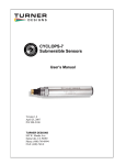
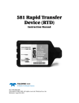
Fluorescence Solutions for Water Monitoring ~~~~~~~~~~~~~~~~~~~~~~~~~~~~~~~~~~ Turner Designs Opti-Trace Fluorometer User’s Manual Version 1.1 March 31, 2010 P/N 998-6700 TURNER DESIGNS 845 W. Maude Ave. Sunnyvale, CA 94085 Phone: (877) 316-8049 (408) 749-0994 FAX: (408) 749-0998 Table of Contents TABLE OF CONTENTS..................................................................................................................... 2 INTRODUCTION................................................................................................................................ 3 DESCRIPTION...................................................................................................................................... 3 INSPECTION AND SETUP ..................................................................................................................... 3 INSTALLATION ................................................................................................................................. 4 PRE-INSTALLATION/INSTALLATION ................................................................................................... 4 POWER AND UTILITIES REQUIRED ...................................................................................................... 4 LOCATION OF OPTI-TRACE AND SAMPLING POINT ............................................................................. 4 MECHANICAL CONNECTIONS ............................................................................................................. 5 PLUMBING KIT INLET/OUTLET SIZE INFORMATION ............................................................................ 5 CALIBRATION AND OPERATION ................................................................................................ 5 SECTION 1 – CALIBRATE YOUR DATA COLLECTION SYSTEM TO THE OPTI-TRACE .............................. 6 SECTION 2 – ADJUSTING THE OUTPUT OF THE OPTI-TRACE ............................................................... 7 SECTION 3 – CHARACTERIZING FOR STANDALONE USE ..................................................................... 8 RECOMMENDED MEASUREMENT PRACTICES .................................................................... 11 1. 2. 3. 4. 5. 6. DETERMINING THE MAINTENANCE INTERVAL ........................................................................ 11 CLEANING THE FLOWCELL ..................................................................................................... 11 REMOVING UNWANTED BUBBLES IN THE SYRINGE .................................................................. 12 REDUCING THE EFFECTS OF TEMPERATURE CHANGES DURING CALIBRATION ......................... 12 LINEAR RANGE AND QUENCHING ........................................................................................... 12 TEMPERATURE CONSIDERATIONS ........................................................................................... 13 WARRANTY...................................................................................................................................... 13 TERMS .............................................................................................................................................. 13 WARRANTY SERVICE ....................................................................................................................... 14 OUT OF WARRANTY SERVICE .......................................................................................................... 14 APPENDIX A ..................................................................................................................................... 15 OPTI-TRACE SPECIFICATIONS .......................................................................................................... 15 APPENDIX B ..................................................................................................................................... 16 OPTI-TRACE WIRING TABLE ............................................................................................................ 16 APPENDIX C – PRE-INSTALLATION/INSTALLATION CHECKLIST ................................. 17 INSTALLATION REQUIREMENTS - CUSTOMER ................................................................................... 17 CUSTOMER REQUIREMENTS - PLUMBER ........................................................................................... 17 CUSTOMER REQUIREMENTS - ELECTRICIAN ..................................................................................... 17 FINAL REQUIREMENTS - CUSTOMER ................................................................................................ 18 APPENDIX D ..................................................................................................................................... 19 FIGURE 7 – INLET PLUMBING KIT DETAILS ...................................................................................... 19 FIGURE 8 – DRAIN PLUMBING KIT DETAILS ..................................................................................... 20 FIGURE 9 - OPTI-TRACE FLUOROMETER, SHOWING IDENTIFICATION OF KEY PARTS ....................... 21 Introduction Description The Turner Designs Opti-Trace fluorometer is an accurate, single channel fluorometer designed to measure and provide an output signal proportional to the concentration of a fluorescent dye. In a representative application, the Opti-Trace will be used with a data collection system to monitor and control the level of treatment chemicals in industrial applications. By combining the Opti-Trace with a data collection system, the exact level of a tracer dye can be measured, which in turn can be used to control the addition of treatment chemicals assuming the tracer dye is tagged to the chemical of interest. The fluorescent tracer dye is measured by passing the water containing the dye/chemical containing water through a sample cell (glass tube) in the Opti-Trace fluorometer. An excitation light source illuminates the solution, and excites the dye in the solution which fluoresces at a different wavelength. The intensity of the emitted light is proportional to the concentration of the dye in the system. The Opti-Trace is designed to provide trouble-free performance with only simple, routine maintenance. Inspection and Setup The shipment package consists of : Opti-Trace Analog Fluorometer, (P/No. 6700-000) configured and factory scaled for the fluorophore of interest, (Rhodamine WT, etc.). Opti-Trace User’s Manual on CD (P/No 998-6700) Inlet Plumbing Kit (P/No. 6700-955) Calibration Kit (P/No. 6700-900) Clean Out Cap Sample Outlet (on Side) Desiccant Plug LuerLock Two Way Valve Sample Inlet Opti-Trace User’s Manual Figure 1 Opti-Trace Fluorometer showing location of user accessible parts Page 3 Installation Pre-Installation/Installation A pre-installation/installation checklist provides important guidelines and information to aid in preparing for installation. See Appendix C for the Opti-Trace checklist. Power and Utilities Required Power: 5 – 30 VDC, Power Consumption 1.5 Watts maximum Signal Output: 4 – 20 mA DC Water Sample: Supplied to fluorometer at 0.5 gpm minimum, and less than 100 psi. (Note: Higher flow rates may require more frequent cleaning of the basket strainer and sample cell). Drain: Sample output from the Opti-Trace should be piped to a drain with no back pressure, i.e. drain pipes must be below the unit. The Opti-Trace should be plumbed as shown in Figures 7 and 8, see Appendix D. The components are included as part of the plumbing accessory kit. It is strongly recommended that the flow switch provided in the plumbing kit be connected to an alarm system that will indicate if the flow of water through the sample cell falls below 0.5 gpm. Location of Opti-Trace and Sampling Point The Opti-Trace is rated for light industrial environments. Do not install within 10 feet/3 meters of devices such as large generators that generate a strong electromagnetic field. It is extremely important to eliminate air entrapment in the sample line. The best way to accomplish this is to sample from the center of the pipe or from the side of the pipe. The unit should not be installed in direct sunlight; this could cause the internal temperature of the unit to be significantly higher than ambient and produce errors or damage the components (Note the maximum environment temperature is specified at 120oF/49oC). Do not mount this instrument on vibrating walls or surfaces. Damage can occur to critical components. Opti-Trace User’s Manual Page 4 Mechanical Connections Refer to Figure 9, Appendix D for the location of the required mechanical connections. Two ¼ inch NPT pipe connections are provided for ¼ inch PVC pipe hook-up. The sample outlet line is ¼ inch female; the sample inlet line is ¼ inch male shut-off valve. Plumbing Kit Inlet/Outlet Size Information The outlet line is ¼ inch NPT (female) to connect to user-supplied ¼ inch male piping; the inlet line is ½ inch NPT (female) to connect to user-supplied ½ inch male piping (see Figures 7 and 8 on pages 19 - 20). IMPORTANT: 1. Sample discharge should flow to an unrestricted drain. Pipe rises greater than 10 feet [3 m] should be avoided. Ensure that the drain cell does not allow the water to siphon off, with the potential risk of the sample water draining out faster than the flow rate through the sample cell. 2. Draining into a pressured system is not recommended. Calibration and Operation This procedure is in 3 parts: 1. Section 1 will describe how to calibrate your data collection system to the signal supplied by the Opti-Trace. It is assumed that your data collection system provides a method to do a linear calibration. 2. Section 2 will describe how to adjust your Opti-Trace if you want to use different settings from the factory standard. The adjustment will consist of setting upper (20 mA) and lower (4mA) output currents that correspond to known concentration levels. These two levels will be chosen to enable a controller to vary the strength of a chemical. It is assumed that instructions in the User Manual for the data logging and control parts of the system will describe how to achieve this. 3. Section 3 will describe how to characterize the Opti-Trace when the application is to use it as a standalone sensor, and it will be required to convert the output current to units of concentration. NOTE: It is important to follow good measurement procedures when calibrating or adjusting the Opti-Trace. See page 11 for a summary of Recommended Measurement Practices. Opti-Trace User’s Manual Page 5 Section 1 – Calibrate your data collection system to the Opti-Trace Equipment Required: a) Opti-Trace fluorometer configured for dye of interest b) DC Power Supply, (Output voltage range 5 – 30 VDC) c) Data Collection system d) Sample of de-ionized water. e) Sample of water with dye at a concentration to give an output around 50% of the maximum expected concentration. Procedure: Measure the blanking current 1. Connect the Opti-Trace fluorometer to the Power Supply and Data Collection System as shown in Fig 2 below. DC Power Supply Opti-Trace Fluorometer 12.00 .015 - + Brown with White Stripe Red White with Black Brown Stripe White Greenwith Blue Stripe Blue with White Stripe Orange 0001: Fluorometer 0002: Current +31.23 +12.12 Data Collection System 1 2 3 A 4 5 6 B 7 8 9 C 0 D Fig 2: Representation of configuration for calibrating a Data Collection System to the Opti-Trace signal output. Opti-Trace User’s Manual Page 6 2. Using a syringe, inject a sample of the de-ionized water through the Luer-Lock valve. Set your data collection system to read “0’ for this sample. Measure the Output Current for the Sample concentration 1. Inject a sample of the test solution into the sensor, Set the data collection system to output the value of the sample. For example, if the concentration of the solution used was 100 ppb, the data collection system could be set to read “100” for this sample. 2. Flush the sensor through with de-ionized water. Section 2 – Adjusting the Output of the Opti-Trace The Opti-trace is shipped from the factory calibrated to a DI water "Blank" and a known concentration of "fluorescent dye" specific to the optical System Blank configuration ordered. (See Test Sensitivity Adjustment Data Results Report included with Adjustment Sensor documentation). There may be a need to adjust your Opti-Trace due to application demands that require a different dynamic range of measurement. The order in which these adjustments are made is important. The 4mA measurement, the minimum output should always be adjusted first, followed by the “System Sensitivity” (dynamic range). Fig 3 showing location of System Sensitivity and Blank adjustments on the bottom of the Opti-Trace sensor. Minimum Output Adjustment Steps: 1. Turn off the process water flow to the Opti-Trace. 2. Ensure the discharge plumbing of the Opti-Trace is not pressurized. 3. If required, temporarily install a DVM capable of mA measurements. The connection points must be in series with the 4-20mA wiring to yield accurate measurements. (See Appendix B for wiring details). 4. Clean / flush the flowcell of the Opti-Trace as outlined in this Operation Manual. 5. Using the provided syringe, inject 120cc of your minimum concentration solution into the Luer-Lock, leave the syringe in place during the adjustment. Opti-Trace User’s Manual Page 7 6. While viewing the 4-20mA measurement, adjust the trim-pot located below the calibration port marked "Blank". Counterclockwise adjustment will lower the measurement, clockwise will increase the measurement. A setting that results in approximately 4mA will yield the best results. As the measurement is in real time there will be some "noise" in the 4mA measurement - achieving exactly 4.00mA is not realistic. Remove the syringe. 7. Note that if your minimum sample has a large fluorescence value, it may not be possible to adjust the minimum level to 4 mA. If this happens, adjust the blank adjustment until the output of the sensor is as low as possible. Sensitivity Adjustment Steps: 1. Turn off the process water flow to the Opti-Trace. 2. Ensure the discharge plumbing of the Opti-Trace is not pressurized. If required, temporarily install a DVM capable of mA measurements. The connection points must be in series wth the 4-20mA wring to yield accurate measurements, (See Appendix B for wiring details). 3. Determine the maximum range of your application and prepare the appropriate fluorescent dye solution equal to approximately 50% of this maximum (equal to ~12mA measurement). 4. Using the provided syringe, inject 120cc of the known concentration of fluorescent dye significant for your application into the calibration port. 5. While viewing the 4 - 20mA measurement, adjust the trimpot located below the calibration port marked "Sensitivity". Counterclockwise adjustment will lower the measurement, clockwise will increase the measurement. As the measurement is in real time there will be some "noise" in the 12mA measurement - achieving exactly 12.00mA is not realistic. 6. Remove the DVM temporarily installed for calibration purposes. Return the Opti-Trace to service by turning on the process water flow. 7. Note that if your sample is out of the range of the Opti-Trace, it may not be possible to adjust the output to 12 mA. Section 3 – Characterizing for Standalone Use Equipment Required a) Opti-Trace fluorometer configured for dye of interest b) DC Power Supply, Output Voltage Range 5 – 30 VDC c) Multimeter to read 0 – 20 mA d) Sample of de-ionized water e) Sample of water with dye at a known concentration, say 30 ppb. Opti-Trace User’s Manual Page 8 Procedure Measure the blanking current 1. Connect the Opti-Trace fluorometer to the Power Supply and Digital Multimeter as shown below. 2. Using a syringe, inject a sample of the de-ionized water through the Luer-Lock. Measure the output current of the sensor (equal to the blank current). Note the reading in Table 1 as indicated. DC Power Supply Multimeter 4.00 12.00 .015 + - 20 mA Red A Common Black Opti-Trace Fluorometer Desiccant Plug Orange Green LuerLock Figure 4: Connections for powering the Opti-Trace, and reading the output current Solution Measured Blank Solution Sample Solution Opti-Trace User’s Manual Sensor Output Current Blank Current Table 1 Page 9 Measure the Output Current for the Sample 1. Inject a sample of the test solution into the sensor, and note the output current in Table 1. Solution Measured Blank Solution Sample Solution Sensor Output Current Blank Current Sample Current Table 1 2. Flush the sensor through with de-ionized water. Calculate the Sensor Calibration Coefficient 1. Assume the tracer dye used has a concentration of 30 ppb. 2. Using the current values for the blank and sample, see following table for example readings, you can calculate the unknown concentration for a known output current: Solution Measured Blank Solution Sample Solution Concentration 0 ppb 30 ppb Sensor Output Current 4 mA 19 mA 3. Using the equation for the straight line through the blank and 30 ppb sample, y = mx + c………. Equation (1) “y” = sample concentration value “x” = sensor output value in mA, “m” is the slope of the response = (sample concentration – blank concentration)/(sample output current – blank output current), “c” is a constant equal to the value of “y” when “x” = 0 Using the values from our example, “m” is calculated as: m = (30 – 0)/(19 – 4) = 30/15 = 2 Substituting for “m”, when “y” = 0 and “x” = 4, (the blank values), we can determine “c” 0 = (2 * 4) – c, so, c = -8 This gives y = 2x – 8 ……..Equation (2) 4. For any value of “x”, the sensor current, the corresponding sample concentration, “y” can be found. 5. Example: Suppose the output current = 10 mA, then the sample concentration = (2 * 10) – 8 = 20 – 8 = 12 ppb. Opti-Trace User’s Manual Page 10 Recommended Measurement Practices 1. Determining the Maintenance Interval The flow cell should always be cleaned as part of the calibration routine. However, it’s not essential to calibrate the sensor each time it’s cleaned. To determine the necessary calibration/cleaning interval, follow these steps; a) Measure a sample of water with dye using the Opti-Trace b) Clean the Opti-Trace flowcell using the brush included in the accessories c) Re-measure the sample used in step (a). d) Calculate the difference in readings and determine whether the difference is outside acceptable limits as defined in your application. If yes, it will be necessary to reduce the amount of time between calibration/cleaning maintenance. 2. Cleaning the Flowcell For routine maintenance, clean the sensor with the supplied brush. For more thorough cleaning, the next step is to use suitable cleaning liquids as described below. Proper eye and skin protection should be worn when using acids to clean the sample cell. a) Close the two-way valve flowcell shut-off valve. (The valve is closed when the handle is horizontal) b) Clean the flowcell by injecting a dilute acidic solution, such as 10% Sulfuric Acid, Hydrochloric Acid, etc, with the accessory syringe into the flowcell. The syringe screws on to the Luer-Lock fitting on the inlet of the flowcell. After filling the syringe with 60 mL of dilute acid, screw the syringe on to the fitting, inject the acid at a slow, steady rate into the flowcell, and allow it to stand for 3 to 5 minutes. Next using a clean 60 mL syringe flush the flowcell thoroughly with 60 mL of blank solution. Finally, clean the cell with the supplied brush. c) The flowcell is now ready to be calibrated. Opti-Trace User’s Manual Figure 5 Opti-Trace fluorometer showing location of inlet, (bottom) and cleaning, (top) valves Page 11 3. Removing unwanted bubbles in the syringe Bubbles trapped in the syringe during injection of the blank or calibration standard are a possible cause of measurement error. To eliminate the bubbles, start with the syringe in a vertical position, and tap it against a solid object to move the bubbles to the needle end of the syringe. Then force the bubbles out by pushing a small amount of solution through the needle end of the syringe. 4. Reducing the effects of temperature changes during calibration It is important to let readings stabilize before recording them during the calibration routine. The readings will probably change from when the dye is first injected into the sample cell as the dye stabilizes to the ambient temperature of the sensor. Normally, the readings will stabilize within a minute or so. 5. Linear Range and Quenching The linear range is the concentration range in which the Opti-Trace output is directly proportional to the concentration of the fluorophore. The linear range begins with the smallest detectable concentration, and spans to an upper limit (concentration) that is dependent upon: the properties of the fluorescent material; the filters used; and the path length. A non-linear relationship is seen at very high concentrations where the fluorescence signal does not increase at a constant rate in comparison to the change in concentration, see Figure 6 below. At even higher concentrations, the fluorescence signal will decrease even though the sample concentrations are continuing to increase. This effect is known as “signal quenching”. Fluorometer Reading Fluorom eter R esponse C urve Sample Quenching Region Sample Linear Region Sam ple C oncentration Figure 6 Graph showing Linear and Quenching Regions of the sample’s response Linearity may be checked by diluting a sample 1:1, or some other convenient ratio. If the sample is still in the linear range, the reading will decrease in direct proportion to the dilution. If the reading does not decrease in direct proportion to the dilution, or if the reading increases, the sample is beyond the linear range of the fluorophore. Opti-Trace User’s Manual Page 12 6. Temperature Considerations Fluorescence is temperature sensitive and depends on the dye used. As the temperature of the sample increases, the fluorescence decreases. For greatest accuracy, determine the temperature coefficient of the dye being used, record the sample temperature and correct the sensor output for changes in temperature. (See following table 2 for examples of dye temperature compensation coefficients). Information on how to apply these corrections is included in the Turner Designs Application Note: A Practical Guide to Flow Measurements, see the following URL: http://www.turnerdesigns.com/t2/doc/appnotes/998_5000.html Correction (/oC) Correction (/oF) Rhodamine WT -0.026 -0.0144 Fluorescein -0.0036 -0.0020 Dye Table 2: Examples of Temperature Corrections for two common fluorescent dyes Warranty Terms Turner Designs warrants the Opti-Trace and accessories to be free from defects in materials and workmanship under normal use and service for a period of 12 months from the date of shipment from Turner Designs with the following restrictions: Turner Designs is not responsible for replacing parts damaged by accident or neglect. Your instrument must be installed according to instructions in the User’s Manual. Damage from corrosion is not covered. Damage caused by customer modification of the instrument is not covered. This warranty covers only Turner Designs products and is not extended to equipment used with our products. We are not responsible for accidental or consequential damages, except in those states where this limitation is not allowed. This warranty gives you specific legal rights and you may have other rights which vary from state to state. Damage incurred in shipping is not covered. Opti-Trace User’s Manual Page 13 Warranty Service To obtain service during the warranty period, the owner shall take the following steps: 1. Write, email or call the Turner Designs Technical Support department and describe as precisely as possible the nature of the problem. Phone: 1 (877) 316-8049 Email: [email protected] 2. Carry out any adjustments or tests as suggested by the Technical Support Department. 3. If proper performance is not obtained you will be issued a Return Materials Authorization number (RMA) to reference. Package the unit, write the RMA number on the outside of the shipping carton, and ship the instrument, prepaid, to Turner Designs. If the failure is covered under the warranty terms, the instrument will be repaired and returned free of charge, for all customers in the contiguous continental United States. For customers outside of the contiguous continental United States who purchased equipment from one of our authorized distributors, contact the distributor. If you purchased directly, contact us. We will repair the instrument at no charge. Customer pays for shipping duties and documentation to Turner Designs. Turner Designs pays for return shipment (custom duties, taxes and fees are the responsibility of the customer). Out of Warranty Service Follow steps for Warranty Service as listed above. If our Technical Support department can assist you by phone or correspondence, we will be glad to, at no charge. Repair service will be billed on a fixed price basis, plus any applicable duties and/or taxes. Shipment to Turner Designs should be prepaid. Your bill will include return shipment freight charges. Address for Shipment: Turner Designs, Inc. 845 W. Maude Ave. Sunnyvale, CA 94085 Opti-Trace User’s Manual Page 14 Appendix A Opti-Trace Specifications Parameter Specification Linearity, (in lab environment over dynamic range) 0.99R2 Power Draw @5V: Max 1.5 W Input Voltage 5 – 30 VDC Signal Output 4 – 20 mA Light Source Light Emitting Diode Detector Photodiode Warm up time 5 seconds Dimensions, (length excludes connector) Length: 5.75” Width: 3.5” Depth: 3.0” Weight 5.0 ozs, 160 gm Opti-Trace User’s Manual Page 15 Appendix B Opti-Trace Wiring Table Opti-Trace Wire Red Function Supply Voltage Connection PSU – Positive Connection 5 – 30 VDC Black Supply Ground, 0VDC PSU – Ground Connection Orange Signal Out to data logger, “A”, 4 – 20 mA DC Multimeter “A” Connection Green Signal Out to data logger “Common”, 4 – 20 mA DC Multimeter “Common” Connection Opti-Trace User’s Manual Page 16 Appendix C – Pre-Installation/Installation Checklist Pre-Installation/Installation Checklist The following checklist is provided so the appropriate preparations may be made prior to equipment start-up. Completion of the listed items is mandatory to assure proper installation and a properly-functioning piece of equipment. 1. ________ ________ Check that the turbidity is less than 150 NTU. 2. ________ ________ Assure water temperatures of 32-140°F. Installation Requirements - Customer 1. ________ ________ Locate the unit within 125 feet from the sample point. 2. ________ ________ Locate the unit out of direct sunlight. 3. ________ ________ Locate the unit where ambient temperatures are 40-120°F/449°C. 4. ________ ________ Locate the unit at least 10 feet/3 meters from devices such as large generators, which require a great deal of electrical power, or generate a strong electromagnetic field. Customer Requirements - Plumber 1. ________ ________ The sample stream must be plumbed to the unit to deliver at a rate >0.5 gpm (between 0.5 and 1.25 gpm is optimal) and <100 psi. One ½-inch and one ¼-inch NPT pipe connections (both female) are provided for PVC pipe hookup (refer to Figure 7 and 8, page 19 - 20). Ensure that the sampling point will avoid air entrapment. 2. ________ ________ Sample from the side of the water line to avoid air entrapment. 3. ________ ________ Provide a free, unrestricted drain for the sample stream, preferably to the tower basin (no back pressure, max. 10 ft/3 m rise). Customer Requirements - Electrician 1. ________ ________ Provide 5-30 VDC, 1.5 Watts electrical service to the Opti-Trace. 2. ________ ________ Terminate flow switch wiring to your alarm system. Continued on next page. Opti-Trace User’s Manual Page 17 Final Requirements - Customer 1. ________ ________ Obtain needed materials (calibration solution, distilled water, dilute acid, calibration kit, flowcell cleaning brushes) Customer’s Responsibilities: This checklist outlines the work that is required prior to start-up. Work is necessary to ensure quality and proper operation. However, if any of these requirements cannot be met, contact Turner Designs Technical Services. In some cases, alternative procedures will still provide reliable results. Opti-Trace User’s Manual Page 18 Appendix D Figure 7 – Inlet Plumbing Kit Details TO OPTI-TRACE OPTI-TRACE INLET PLUMBING – PVC PLUMBING Opti-Trace User’s Manual Page 19 Figure 8 – Drain Plumbing Kit Details Sample Outlet From Opti-Trace Unit Opti-Trace User’s Manual Page 20 Figure 9 - Opti-Trace Fluorometer, Showing Identification of Key Parts Opti-Trace User’s Manual Page 21 Turner Designs 845 W. Maude Ave. Sunnyvale, CA 94085 Phone: (408) 749-0994 Toll Free (877) 316-8049 © Copyright 2004, Turner Designs P/No. 998-6700 Opti-Trace User’s Manual Page 22