1
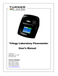
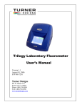
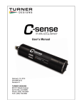
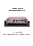
CYCLOPS-7
Submersible Sensors
User’s Manual
Version 1.6
April 25, 2007
P/N 998-2100
TURNER DESIGNS
845 W. Maude Ave.
Sunnyvale, CA 94085
Phone: (408) 749-0994
FAX: (408) 749-0
Table of Contents
TABLE OF CONTENTS ................................................................................................................................... 2
INTRODUCTION................................................................................................................................................ 3
DESCRIPTION .......................................................................................................................................................3
INSPECTION AND SETUP ....................................................................................................................................3
FUNCTIONAL TEST .............................................................................................................................................4
MEASUREMENTS WITH CYCLOPS-7 ..................................................................................................... 5
INTRODUCTION ...................................................................................................................................................5
SETTING THE GAIN .............................................................................................................................................5
GAIN DETERMINATION PROCEDURE ...............................................................................................................5
TURBIDITY CYCLOPS.................................................................................................................................... 6
INTRODUCTION ...................................................................................................................................................6
CALIBRATION......................................................................................................................................................6
RECOMMENDED MEASUREMENT PRACTICES FOR USING YOUR CYCLOPS-7 IN
THE LAB................................................................................................................................................................ 8
U SING THE SECONDARY STANDARD, (OPTIONAL A CCESSORY)..................................................................9
U SE OF THE SOLID SECONDARY STANDARD FOR IN VIVO CHLOROPHYLL APPLICATIONS:..................10
U SE OF THE SOLID SECONDARY STANDARD FOR DYE TRACING APPLICATIONS:...................................11
RECOMMENDED MEASUREMENT PRACTICES .............................................................................11
LINEAR RANGE AND QUENCHING..................................................................................................................11
TEMPERATURE CONSIDERATIONS..................................................................................................................12
CARE AND MAINTENANCE.......................................................................................................................12
RINSING..............................................................................................................................................................12
CLEANING THE OPTICS ....................................................................................................................................12
WARRANTY.......................................................................................................................................................13
TERMS ................................................................................................................................................................13
W ARRANTY SERVICE .......................................................................................................................................13
OUT OF W ARRANTY SERVICE ........................................................................................................................14
APPENDIX A......................................................................................................................................................15
CYCLOPS-7 SPECIFICATIONS.......................................................................................................................15
APPENDIX B ......................................................................................................................................................16
CYCLOPS-7 W IRING TABLE.........................................................................................................................16
GAIN SWITCHING TABLE .................................................................................................................................16
APPENDIX C......................................................................................................................................................17
CYCLOPS-7 PIGTAIL CABLE AND CONNECTOR INFORMATION ..............................................................17
APPENDIX D......................................................................................................................................................18
REQUEST FOR QUOTE TEMPLATE FOR NON-STANDARD PIGTAIL CABLE LENGTH/CONNECTOR FOR
U SE W ITH CYCLOPS-7..................................................................................................................................18
CYCLOPS-7 User’s Manual
Page 2
APPENDIX E.......................................................................................................................................................19
M ETHOD 1 - STATIC GAIN CONTROL ............................................................................................................19
M ETHOD 2 - DYNAMIC GAIN CONTROL .......................................................................................................19
INDEX ...................................................................................................................................................................21
Introduction
Description
The Turner Designs CYCLOPS-7 Submersible Fluorometer/Turbidimeter is an
accurate single channel detector that can be used for many different applications.
This instrument can be designed to detect pigment fluorescence, dye fluorescence for
dye tracing applications, fluorescence of dissolved organic matter, or be used as a
turbidimeter. It is intended to be integrated into a multi-parameter system to obtain
its power and to deliver an output voltage to the system data logger, which is
proportional to the concentration of the fluorophore, particle or compound of
interest.
When calibrated with a standard of known concentration, the CYCLOPS-7 output
voltage can be correlated to provide data of the actual concentration of the target
fluorophore.
Inspection and Setup
The CYCLOPS-7 shipment package consists of:
•
CYCLOPS-7 Analog Detector, (P/No. 2100-000)
configured and factory scaled for the specified analysis,
(see identification letter stamped on the connector for
specified analysis, “C” = Chlorophyll, “R” = Rhodamine,
“F” = Fluorescein, “P” = Phycocyanin “E” = Phycoerythrin
“U” = CDOM, “O” = Crude Oil, “B” = Optical Brighteners
“T”= Turbidity).
• CYCLOPS-7 Documentation Kit (P/No. 2100-998) includes User’s Manual on
CD (CD P/No 005-2100) and Quick Start Guide
• Calibration Certificate
• Quick-start Guide, Flow Through Cap assembly instructions, Secondary
Standard Instructions and In Vivo Calibration Procedure all on above CD
Optional Accessories include:
Cable Assy-C7 Pigtail, 2 Ft, P/No. 2100-750
Solid Standard, P/No. 2100-900
Additional Equipment required for functional tests:
DC Power Supply, 3 - 15 VDC, >100 mA
Multimeter to read 0 – 5 VDC
CYCLOPS-7 User’s Manual
Page 3
Functional Test
To perform a functional check on the CYCLOPS-7, connect the interface colored
wires to the power supply and multimeter as shown in Figure 1.
Note:
Supply voltages greater than 15 VDC will result in damage to the sensor.
DC Power Supply
Multimeter
12.00 .015
+
3.52
-
10 VDC
PSU Positive
Connection, (Red)
LED
Light
Output
Supply Ground
0 VDC, (Black)
+
Signal
Output “+”
(White)
CYCLOPS-7
Fluorometer
Analog
Ground “-”
(Green)
Figure 1
CYCLOPS-7 connections
functional
for
check
X10 Gain (Blue)
X100 Gain (Brown)
X1 (Low) Gain,
Leave both wires disconnected
for Functional Check
With the CYCLOPS-7 connected as shown in Figure 1 above, make the following
functional checks:
-
The LED is on
The multimeter reads >0 VDC
Moving the light source close to your hand causes the output voltage to
increase.
CYCLOPS-7 User’s Manual
Page 4
-
Measurements with CYCLOPS-7
Introduction
The following procedure will describe how to make measurements with the
CYCLOPS-7. Also, it will describe how to use the accessory Solid Secondary
Standard to make absolute (or quantitative) measurements. (Note that to make
accurate and repeatable measurements it is important to keep the sensor clean, see
page 12 for information on cleaning your sensor).
Setting the Gain
The gain setting refers to the sensitivity adjustment of the sensor. There are three gain
settings; X1, X10 and X100. As the gain increases, the sensitivity increases and the
concentration range decreases. All three gain settings can be used, however, you must
determine which gain to use prior to deployment and have an integration cable made to
activate a specific gain (see Appendix B). In other words, only one gain setting can be
used at a time, this is referred to as ‘Static Gain Control”. If you want the ability to
utilize all three gains with a multi-parameter system, such as a CTD, you will need to
purchase three separate integration cables.
In most instances the X10 gain will provide the appropriate sensitivity and range. If you
are working in very low concentration applications (<2 µg/L chl a or, <5 ppb rhodamine
WT), the X100 gain is recommended and if very high concentrations are expected (>40
µg/L chl a or >80 ppb rhodamine WT) the X1gain is recommended.
If you are uncertain of which gain setting to use you can take readings of a
representative sample of water in the laboratory and determine which gain is the most
appropriate.
Customers wanting to dynamically change the gain ranges to achieve the optimum
operating range should refer to “Method 2 – Dynamic Gain Control” in Appendix E for
how to interface with a Data Collection System with programmable outputs.
Gain Determination Procedure
1) For in vivo chlorophyll applications, take a natural sample of water from a sampling
station where you plan to deploy the CYCLOPS-7. Applying good measurement
practices, store it properly, and quickly transport it to a laboratory where you have
the CYCLOPS-7 connected to a multimeter and DC power source. (see Figure 1)
2) Pour the water sample into to a clean glass beaker and submerge the optical end of
the CYCLOPS-7 (See the section on “Recommended Measurement Practices for
using your CYCLOPS-7 in the Lab” for how best to accomplish these steps).
3) Activate the X10 gain setting (see Wiring Table on page 16 if you believe the
sample to represent a typical condition (i.e. not a bloom or other abnormal event).
You would like to obtain a signal from the sample that is significantly higher than a
blank sample, (De-ionized water or filtered seawater), but not a signal that is close to
the maximum of 5 Volts.
CYCLOPS-7 User’s Manual
Page 5
4) If the sample signal is high, (>3.0 V for example) you may choose to use the X1 gain
instead of the X10 gain setting so that you avoid going over scale once you deploy
the CYCLOPS-7.
5) If the sample signal is very low (<0.3V) you may choose to use the X100 gain
setting to achieve higher sensitivity but a smaller measurable range
This process is even easier for dye tracing applications. Simply create the dye
dilution of interest and record what signal level it provides on the three gain settings.
Once the appropriate gain setting has been determined, order an integration cable for
that particular gain. See Appendix D for more information on integration cables.
Turbidity Cyclops
Introduction
The Turbidity Cyclops measures turbidity using an 850nm light source and detection
of scattered light at a 90-degree angle, which is similar to many modern day
benchtop turbidimeters. This unit provides a quick and accurate way to determine in
situ turbidity, eliminating the collection and storage of samples and minimizing the
potential error associated with sample handling and processing.
Calibration
Calibrating the Turbidity CYCLOPS is a simple process, which requires the use of
calibration standards. Turner Designs recommends purchasing Amco Clear Analytical
Turbidity Standards for non-ratio instruments because these standards are non-toxic
safe solutions consisting mainly of de-ionized water that comes prepared in a broad
range of concentrations and has a shelf life guaranteed for one year. The Turbidity
CYCLOPS can be calibrated using a single point calibration, which correlates a
known standard to the signal measured from a typical sample.
1) Connect the CYCLOPS-7 to a power source and measure the turbidity of a
typical water sample from the source being monitored, recording the voltage
output of the sample
2) Set the CYCLOPS-7 to the proper gain (see Gain Setting for explanation on how
to set the gain)
3) Use turbidity standards of known concentrations (NTU) and create a correlation
between the standard (NTU) and the voltage output (volts) (Note: make sure to
use a standard concentration that can be read on the same gain setting as typical
samples) (See page 15 for typical NTU range at gains: 1X, 10X, and 100X)
4) Once correlation has been made, use the following equation to calculate turbidity
values for future measurements
Sample (NTU) = [NTUStd./Std.volts] * Samplevolts
NTU Std. = Concentration of Standard used for calibration
CYCLOPS-7 User’s Manual
Page 6
Std.volts = voltage reading from known concentration of standard
Samplevolts = voltage reading from samples
5) Switching gains will require re-calibration if the signal has exceeded the
maximum voltage for a gain setting
CYCLOPS-7 User’s Manual
Page 7
Recommended Measurement Practices for Using Your
Cyclops-7 in the Lab
The following steps will improve the accuracy and repeatability of your
measurements, especially at low concentration levels:
1. Use a Glass Beaker for your water samples. (Avoid plastic beakers – plastic
fluoresces and will interfere with the sample fluorescence)
2. Place the glass beaker on a Non-Reflective Surface, preferably black.
3. Ensure that the sensor is more than 3 inches above the bottom of the glass
beaker.
4. Ensure that the sensor is in the center of the glass beaker, and has more than 2
inches clearance between the cirumference of the sensor and the inside surface
of the beaker. Turner Designs recommends using a 1L Glass Beaker for
measurements with CYCLOPS-7 units.
5. Check that the optical surface of the sensor is free of air bubbles.
6. Be sure your sensor is calibrated, (see page 9 for Calibration Procedure).
7. To maximize consistency between measurements, place sensor at exactly the
same height for each sample. This is most easily done using a Lab Stand.
Calibrated
Sensor
>2 inches
all round
Glass
Beaker
>3 inches
No Air Bubbles
On Optical Surface
CYCLOPS-7 User’s Manual
Dark/Black NonReflective Surface
Figure 2
Summary of good
measurement practices
for using a submersible
fluorometer in the lab.
Page 8
Using the Secondary Standard, (Optional Accessory)
The following information will describe how to use the Solid Secondary Standard,
P/No. 2100-900, with CYCLOPS-7 sensors (Note: The Turbidity Cyclops does not
have a solid secondary standard).
The two main benefits of using the Solid Secondary Standard are:
1) It can be used in place of a primary liquid standard once a correlation between a
primary standard and the solid standard has been established.
2) It can be used to check the stability of the instrument, and/or check for loss in
sensitivity resulting from the growth of bio-fouling organisms on the sensor
optics.
The Solid Secondary Standard provides a very stable fluorescent signal. It has an
adjustment screw so that you can tune the Solid Standard to provide a signal to
match a specific sample.
Installing the Secondary Standard
1) Before installing the Solid Standard you must ensure that the optical surface of
the CYCLOPS-7 is completely clean and dry. The Solid Standard is indexed and
it must be installed so that the indexing is precisely aligned for proper use (see
Figure 3).
2) To install, place the Solid Standard on to the optical end of the CYCLOPS-7.
3) With the Solid Standard fully pressed on, rotate in either direction until you feel the
CYCLOPS-7
Solid Standard
indexing mark
Figure 3.
Align the index mark and
indexing ball when installing
CYCLOPS-7 in the Solid
Secondary Standard.
Solid Standard
indexing ball
Solid Standard indexing ball click into the indexing mark on the CYCLOPS-7.
4. To begin, use a flat-head screwdriver to unscrew the locking nut as far as it will
go.
5. Next, to change the signal level, use the green screwdriver provided and insert
the blade through the hole in the locking nut. Rotate it until it engages with the
CYCLOPS-7 User’s Manual
Page 9
adjustment screw that is beneath the locking nut. Now the screw can be used to
adjust the signal level as necessary.
Lock Nut
Adjustment screw
is located under the
locking nut
Figure 4
Insert the supplied green
screwdriver through the
calibration hole in the locking
nut to reach the adjustment
screw.
6. Once the desired reading has been obtained, the locking nut should be screwed
down so that the adjustment screw is held firmly in place.
7. Finish by noting the output voltage and gain setting used, (X1, X10 or X100) in
the “Value” space on the Secondary Standard label
8. Note that the response of every solid standard is unique. Hence, a new correlation
must be determined for every sensor. For future identification, use the “ID” space
on the label for a unique identifier for the Secondary Standard.
Use of the Solid Secondary Standard for In Vivo Chlorophyll
Applications:
1. To establish a correlation between a known chlorophyll concentration and the
fluorescence output voltage immerse the sensor in a sample containing algae and
note the sensor output voltage and gain setting used, (x1, x10 or x100).
2. Dry off the CYCLOPS-7, attach the Solid Standard, (with the same gain setting),
and adjust the Solid Standard to produce the same output voltage from the sensor
as in step 1, (turning the Secondary Standard adjustment screw clockwise
produces a lower signal).
3. Next, perform a chlorophyll extraction using a Laboratory Fluorometer,
Spectrophotometer or HPLC to determine the actual chlorophyll a concentration
in the sample 1 . This will provide the correlation of actual chlorophyll a
concentration for the sensor output voltage at that given gain setting.
4.
Now, at any time, the Solid Standard can be used to check/establish a new
correlation between a known equivalent concentration and the current
1
Information on doing a chlorophyll extraction can be found on the Turner Designs web site at this
URL: http://www.turnerdesigns.com/t2/doc/appnotes/998_9000.html
CYCLOPS-7 User’s Manual
Page 10
CYCLOPS-7 output voltage, (CYCLOPS-7 must be on the same gain setting as
in Step 1).
Use of the Solid Secondary Standard for Dye Tracing Applications:
The Solid Secondary Standard accessory can also be used to check the fluorescence
stability for making dye concentration measurements. If necessary, the Solid
Standard can be used to establish a new correlation voltage without the need to use a
calibration solution each time.
1. To use the Solid Standard to establish a correlation between a known dye
concentration and the fluorescence output voltage, immerse the sensor in a dye
solution of known concentration, say 50 ppb, and note the sensor output voltage
and gain setting used.
2. Dry off the optical end of the CYCLOPS-7, attach the Solid, and adjust to
produce the same output voltage from the sensor as in step 1, (turning the
secondary standard adjustment screw clockwise produces a lower output).
3. Now, at any time, the Secondary Standard can be used to check/establish a new
correlation between a known equivalent concentration and the current
CYCLOPS-7 output voltage.
4. Comprehensive information on dye trace measurements can be found at the
following Turner Designs URL:
http://www.turnerdesigns.com/t2/doc/appnotes/main.html#fluorescent
(Note: There is no Solid Secondary Standard available for Turbidity Cyclops)
Recommended Measurement Practices
Linear Range and Quenching
The linear range is the concentration range in which the CYCLOPS-7 output is
directly proportional to the concentration of the signal. The linear range begins with
the smallest detectable concentration and spans to an upper limit (concentration) that
is dependent upon the properties of the material, filters used, and path length.
A non-linear relationship is seen at very high concentrations where the signal does
not increase at a constant rate in comparison to the change in concentration, see
Figure 5 below. At even higher concentrations, the signal will decrease even though
the sample concentrations are continuing to increase. This effect is known as “signal
quenching”.
Linearity can be checked by diluting a sample 1:1 or some other convenient ratio. If
the sample is still in the linear range, the reading will decrease in direct proportion to
the dilution. If the reading does not decrease in direct proportion to the dilution, or if
the reading increases, the sample is beyond the linear range.
CYCLOPS-7 User’s Manual
Page 11
Fluorometer
Reading
Fluorometer Response Curve
Sample
Quenching Region
Sample
Linear Region
Sample Concentration
Figure 5
Graph showing Linear
and Quenching Regions
of the sample’s response
Temperature Considerations
Fluorescence is temperature sensitive. As the temperature of the sample increases,
the fluorescence decreases. For greatest accuracy, record the sample temperature
and correct the sensor output for changes in temperature.
For further information on how temperature, light, water quality and the
physiological state of the algal cells can all affect the measurement of chlorophyll a,
please refer to the application section of Turner Designs’ web site at the following
URL:
http://www.turnerdesigns.com/esupport/understanding.html
Care and Maintenance
Rinsing
The CYCLOPS-7 should be rinsed or soaked in freshwater following each
deployment, ideally until it is completely clean again.
Cleaning the Optics
The optical window should be visually inspected after each deployment following a
soaking in fresh water. If cleaning is needed, use optical tissue to clean the window
with soapy water.
Note: The CYCLOPS should not come in contact with any organic
solvents (ie. acetone, methanol) or strong acids and bases.
The UV Cyclops-7 models are the ONLY Cyclops-7 sensors that can be
calibrated with Quinine Sulfate standards made in Hydrosulfuric Acid.
All other Cyclops-7 models CAN NOT be used in Hydrosulfuric Acid.
CYCLOPS-7 User’s Manual
Page 12
Warranty
Terms
Turner Designs warrants the CYCLOPS-7 Fluorometer/Turbidimeter and accessories
to be free from defects in materials and workmanship under normal use and service
for a period of 12 months from the date of shipment from Turner Designs with the
following restrictions:
The instrument and accessories must be installed, powered and operated in
compliance with the directions in this CYCLOPS-7 User’s Manual and directions
accompanying the accessories.
Damage incurred in shipping is not covered
Warranty Service
To obtain service during the warranty period, the owner shall take the following
steps:
Write or call the Turner Designs Technical Support Department and describe as
precisely as possible the nature of the problem.
Phone: 1 (877) 316-8049
E-Mail: [email protected]
Carry out minor adjustments or tests as suggested by the Technical Support
Department.
If proper performance is not obtained, ship the instrument, prepaid, to Turner
Designs, with a statement of shipping charges. The instrument will be repaired and
returned free of charge, along with a check to cover shipping charges, for all
customers in the contiguous continental United States.
For customers outside of the contiguous continental United States, and who have
purchased our equipment from one of our authorized distributors, contact the
distributor. If you have purchased direct, contact us. We will repair the instrument at
no charge: shipment; documentation; etc; charges will be billed at cost to the
customer.
NOTE! The instrument or accessories should not be returned without first contacting
Turner Designs. Prior correspondence, including an RMA number is needed:
a. To ensure that the problem is not a customer solvable one, easily handled in your
laboratory, saving the end-user time and money.
b. To specifically determine the nature of the problem, so that repair can be rapid,
with particular attention paid to the defect you have noted.
CYCLOPS-7 User’s Manual
Page 13
Out of Warranty Service
Proceed exactly as for Warranty Service, above. If our service department can assist
you by phone or correspondence, we will be glad to, at no charge.
Repair service will be billed on a fixed price basis, plus any applicable duties and/or
taxes. Shipment to Turner Designs should be prepaid. Your bill will include return
shipment freight charges.
Address for Shipment:
Turner Designs
845 W. Maude Ave.,
Sunnyvale, CA 94085
Phone: (408) 749-0994
CYCLOPS-7 User’s Manual
Page 14
Appendix A
CYCLOPS-7 Specifications
Parameter
Minimum Detection Limit
Dynamic Range
(Depends on gain setting)
Linearity, (over dynamic range for lab environment)
Specification
0.03 µg/L Chlorophyll a
0.04 ppb Rhodamine WT
150 cells/mL Cyanobacteria
0.04 NTU Turbidity
X1: 0 – 500 µg/L, Chl a
X10: 0 – 50 µg/L, Chl a
X100: 0 – 5 µg/L, Chl a
X1: 0 – 1,000 ppb, RWT
X10: 0 – 100 ppb, RWT
X100: 0 – 10 ppb, RWT
X1: 0 – 2,000,000 cells/mL PC or PE
X10: 0 – 200,000 cells/mL PC or PE
X100: 0 – 20,000 cells/mL PC or PE
X1: 0 – 3000 NTU, Turbidity
X10: 0 – 1000 NTU, Turbidity
X100: 0 – 100 NTU, Turbidity
0.99R2
Power Draw
@3V: Max 360 mW
=5V: Max 265 mW
Input Voltage
3 – 15 VDC
Signal Output
0 – 5 VDC
Temperature Range
Ambient: 0 to 50 °C
Light Source
Light Emitting Diode
Excitation Wavelength
Detector
Chl 460 nm, RWT 550 nm, PC 595 nm, PE 528 nm,
Turbidity 850 nm
Chl 620 - 715 nm, RWT 590 - 715nm
PC 670 nm, PE 573 nm, Turbidity 850 nm
Photodiode
Detection Wavelength
300 – 1,100 nm
Warm up time
5 seconds
Dimensions, (length excludes connector)
Length: 4.3”, 10.9cm
Weight
5.0 ozs, 160 gm
Depth Rating
600 meters
Housing Material
316 Stainless Steel
Emission Wavelength
CYCLOPS-7 User’s Manual
Water Temp: -2 to +50 °C
Diameter: 0.875”,2.22cm
Page 15
Appendix B
CYCLOPS-7 Wiring Table
CYCLOPS- 7
Wire
Pin Number
Red
1
Function
Connection
Supply Voltage
PSU – Positive Connection
3 – 15 VDC
Black
2
Supply Ground, 0VDC
PSU – Ground Connection
White
3
Signal Out to data logger,
“+”, 0 – 5VDC
Multimeter Positive
Connection
Green
4
Analog Ground “-”, 0 VDC Multimeter Negative
Connection
Blue
5
X10 Gain, (Medium
Sensitivity)
See table below
Brown
6
X100 Gain, (High
Sensitivity)
See table below
Gain Switching Table
Gain 10
(Blue)
Gain 100
(Brown)
Gain
Chl Range
(µg/L)
RWT
Range
(ppb)
TRB
Range
(NTU)
Not connected
Not connected
X1
0 - 500
0 – 1,000
0-3000
Connected to
analog ground
Not connected
X 10
0 – 50
0 - 100
0-1000
Not connected
Connected to
analog ground
X 100
0–5
0 - 10
0-100
CYCLOPS-7 User’s Manual
Page 16
Appendix C
CYCLOPS-7 Pigtail Cable and Connector Information
Figure 7
Dimension details of 24” length cable with 20 gauge colored leadwire, connects to 6
Figure 8
Female locking sleeve,
(Impulse P/No. MCDLS-F)
Figure 9
In-line connector contact
configuration, (connects
to CYCLOPS-7).
See Appendix D for a Quote Request
template to order a non-standard pigtail
cable length/connector for use with the
CYCLOPS-7 Fluorometer
pin male connector. (Cable manufacturer/Part No: IMPULSE/MCIL-6-FS)
A Maximum cable length up to 300 meters can be connected to the CYCLOPS if
the following conditions are met.
1) The cable is shielded and contains 20 gauge conductor size or greater (ie
Belden No. 8426 cable).
2) The 0-5 volt Analog output is connected to a device (ie Data Logger) with an
input impedance of 1 MegOhm or greater.
3) The supply Voltage to the CYCLOPS is between 5 and 15 volts.
CYCLOPS-7 User’s Manual
Page 17
Appendix D
Request for Quote Template For Non-Standard Pigtail Cable
Length/Connector For Use With CYCLOPS-7
To request a quote from Impulse Enterprise for a custom pigtail cable/connector,
follow these steps:
I)
II)
III)
IV.
V.
Complete the 6 lines below between the asterisks (*) with your specific
information.
Highlight the lines between the asterisks (*) and copy to the PC clipboard.
Paste the information into the “Comments” field on the Contact Us page on
the Impulse Enterprise web page at the following URL:
http://www.impulse-ent.com/inquiry.html
Complete the remaining fields of the Impulse Enterprise <Contact Us> e-mail
form
Click on “Send E-Mail”.
*************************************************
Please quote for a custom pigtail cable/connector for use with Turner Designs
CYCLOPS-7 fluorometer to meet the following requirements:
1. Pigtail is required for integration with ____________________
(Identify multi-parameter system as appropriate)
2. Cable Length (to include connectors)___________, (see Page 15 for max length)
(State units, feet, meters, etc.)
3. Configured for ____X1, ____X10, _____X100 gain range on CYCLOPS-7
(Put a checkmark against desired gain)
4. Required connector on non-CYCLOPS end of pigtail: _____________________
(Provide sufficient information for Impulse Enterprise to request a quote for the
required “host” end of cable)
5 Pin out from Host End to CYCLOPS end: _______________________________
or advise:
a. Supply Voltage (+) from Host is carried on pin _______
b. Supply Ground from Host is carried on pin ________
c. Analog Signal to Host is carried on pin _______
d. Analog Ground to Host is carried on pin _______
Provide sufficient information for Impulse Enterprise to make the proper
electrical hook-up between the two connector ends)
6. No. of Pigtails required_____________________
(Provide contact details if different from your information entered in the Impulse
Enterprises fields on their “Contact Us” e-mail form.
For assistance from Turner Designs, call 1 877 316-8049
For assistance from Impulse Enterprise, call 1 800 327-097
CYCLOPS-7 User’s Manual
Page 18
Appendix E
Controlling the Gain of CYCLOPS-7
The operating range can either be set to one of the 3 available ranges, which will be
referred to as "Static Gain Control"; or it can be dynamically changed to achieve the
optimum operating range, referred to below as "Dynamic Gain Control". The first
approach is applicable to using the CYCLOPS-7 as a stand-alone sensor. The second
approach is applicable to when the CYCLOPS-7 is integrated into a system with control
capability.
Both methods are implemented by grounding or driving Low the appropriate Gain
Control pin. The X10 and X100 Gain Control pins are normally in a "1" or "High" state
if they are not connected to anything. This means the CYCLOPS default is to be in the
X1 (largest concentration range) mode.
The CYCLOPS-7 can be put into higher gain, lower concentration range modes by
connecting either the X10 or X100 pin (but not both at the same time) to ground.
Method 1 - Static Gain Control
Connect the X10 or X100 pin to the analog ground pin of the CYCLOPS-7 pigtail
connector. See the Gain Switching Table in Appendix B to determine the required
configuration for desired gain range/measurement range. See Appendix C for Pigtail
Cable and Connector information. Also, see “Setting the Fluorometer Gain” on page 5
for more information on “Static Gain Control”.
Method 2 - Dynamic Gain Control
If you have a Data Collection System (DCS) that has programmable outputs you can use
them to control the CYCLOPS-7 gain signals. Following are three common output types
found in Data Collection Systems and how to connect them to the CYCLOPS-7. Refer to
the manual of your DCS to determine which is appropriate. For those who want the
technical data: the X10 and X100 Gain Control pins of the CYCLOPS-7 are connected
internally to the input of a Schmitt trigger inverter, part number 74LVC1G14, and a
100K ohm pull-up resistor. Both use a 5-Volt power supply.
Output type 1: Digital Signals
Logic signals can be used to drive the Gain Control pins. In most cases you can connect
the digital signal output of the DCS directly to the CYCLOPS-7 Gain Control pins. To
drive them high, the voltage should be 3.0 volts minimum, 5 volts maximum. To drive
them low, the voltage should be 1-Volt maximum, 0 Volts minimum. You may need to
connect the CYCLOPS-7 analog ground to the DCS ground.
Output type 2: Open Collector Signals
This type of output is either open or connected to ground. Connect the CYCLOPS-7
Gain Control pins directly to these outputs. You may need to connect the CYCLOPS-7
analog ground to the DCS ground.
Output type 3: Relays
CYCLOPS-7 User’s Manual
Page 19
Relays act as a controllable switch. Connect one end of the relay to the CYCLOPS-7
analog ground. Connect the other end of the relay to the CYCLOPS-7 Gain Control pin.
CYCLOPS-7 User’s Manual
Page 20
Index
A
O
Analog Ground “-”,........................................... 16
Analog Output voltage “-”,.............................. 16
Analog Output voltage “+”,............................. 16
optical window...................................................12
Out of Warranty Service...................................14
D
Description ........................................................... 3
Detector............................................................... 15
Dynamic Range ................................................. 15
E
Emission Wavelength....................................... 15
Excitation Wavelength..................................... 15
P
Power Draw.........................................................15
PSU – Ground Connection...............................16
PSU – Positive Connection..............................16
R
Rinsing.................................................................12
S
Gain switching signal 1 .................................... 16
Gain switching signal 2 .................................... 16
Signal Out to data logger,.................................16
Solid Standard ......................................................3
Supply Ground ...................................................16
Supply Voltage...................................................16
I
T
Input Voltage ..................................................... 15
Temperature Range............................................15
temperature sensitive.........................................12
Turbidity................................................................6
G
L
LED........................................................................ 4
Light Source....................................................... 15
linear range......................................................... 11
Linearity.............................................................. 15
W
Warranty..............................................................13
Warranty Service................................................13
M
Minimum Detection Limit ............................... 15
CYCLOPS-7 User’s Manual
Page 21
Turner Designs
845 W. Maude Ave.
Sunnyvale, CA 94085
Phone: (408) 749-0994
Toll Free (877) 316-8049
© Copyright 2003, 2004 Turner Designs
P/No. 998-2100
CYCLOPS-7 User’s Manual
Page 22