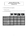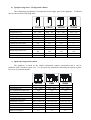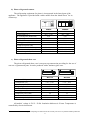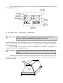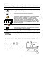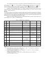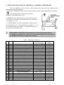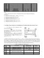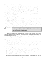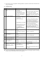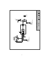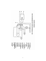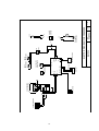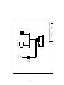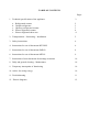
1
TABLE OF CONTENTS
Pages
1. Technical specifications of the appliance
a.
b.
c.
d.
e.
2
Refrigerated counter
Upright refrigerator
Open top refrigerated counter
Pizza refrigerated counter
Pizza refrigerated show case
2
3
3
4
4
2. Transportation – Positioning – Installation
5
3. Safety instructions
6
4. Instructions for use of thermostat BIT12RU
6
5. Instructions for use of thermostat SMD12
8
6. Instructions for use of thermostat MTR11
9
7. Instructions of new thermostat for drainage resistance
10
8. Daily and general cleaning – Maintenance
10
9. Temporary interruption of functioning
10
10. Advice for saving energy
10
11. Troubleshooting
11
12. Electric diagrams
12
READ CAREFULLY THE
FOLLOWING INSTRUCTIONS
BEFORE USE.
1. Technical specifications of the appliance
a) Refrigerated counter
The refrigerating equipment is incorporated in the lateral part of the appliance. Technical
data are shown at the following table:
Capacity (Lt)
*Temperature (ºC)
El. Consumption (KWh/24 h)
Weight (Kg)
Freon
Cooling power (W)
Compressor power (HP)
Dimensions out (cm)
Dimensions in (cm)
Dimensions packed (cm)
Number of shelves
Dimensions of shelves (mm)
BP7300
PN99
PN999
PN9999
266
0ºC ~ 10ºC
5,12
100
R134a
773
1/4
106,5 x 70 x
86
95,5 x 58 x 48
352
0ºC ~ 10ºC
5,12
122
R134a
773
1/4
433
0ºC ~ 10ºC
5,12
130
R134a
773
1/4
588
0ºC ~ 10ºC
6,81
154
R134a
1022
3/8
156 x 70 x 86
101 x 58 x 60
179 x 70 x 86
124,5 x 58 x 60
224 x 70 x 86
169 x 58 x 60
108 x 75,5 x 99
157 x 75,5 x 91
180 x 75,5 x 91
225 x 75,5 x 91
2
325 x 555
2
325 x 555
3
325 x 555
4
325 x 555
* Temperature is controlled by electric thermostat.
2
b) Upright refrigerator – Refrigerated cabinet
The refrigerating equipment is incorporated in the upper part of the appliance. Technical
data are shown at the following table:
Capacity (Lt)
*Temperature (ºC)
El. Consumption (KWh/24 h)
Weight (Kg)
Freon
Cooling power (W)
Compressor power (HP)
Dimensions out (cm)
Dimensions in (cm)
Dimensions packed (cm)
Number of shelves
Dimensions of shelves (mm)
CA170
CB170
CE2140
CF2140
679
0ºC ~ 10ºC
6,81
114
R134a
1022
3/8
679
-20ºC ~ 0ºC
7,46
115
R404a
798
3/4
1471
0ºC ~ 10ºC
8,83
175
R134a
1560
1/2
1471
-20ºC ~ 0ºC
9,81
175
R404a
1140
1
85 x 70 x 208
73 x 60 x 155
86,5 x 72,5 x
218
3
534 x 690
85 x 70 x 208
73 x 60 x 155
86,5 x 72,5 x
218
3
534 x 690
85 x 140 x 208
73 x 130 x 155
86,5 x 142,5 x
218
6
534 x 690
85 x 140 x 208
73 x 130 x 155
86,5 x 142,5 x
218
6
534 x 690
c) Open top refrigerated counter
The appliance is based on the simple refrigerated counter construction and it can be
produced with a luminous glass case. It is an open top construction allowung the option to place
two rows of gastronorm pans.
Capacity (Lt)
*Temperature (ºC)
El. Consumption (KWh/24 h)
Weight (Kg)
Freon
Cooling power (W)
Compressor power (HP)
Dimensions out (cm)
Dimensions in (cm)
Dimensions packed (cm)
Dimensions of shelves (mm)
Number of G/N pans
BS7300
ZQ99
ZQ999
266
+2ºC ~ 10ºC
5,34
130
R134a
773
1/4
106,5 x 70 x 129
95,5 x 58 x 48
108 x 75,5 x 135
325 x 555
12
352
+2ºC ~ 10ºC
7,03
151
R134a
1022
3/8
156 x 70 x 129
101 x 58 x 60
157 x 55,5 x 135
325 x 555
12
433
+2ºC ~ 10ºC
7,03
166
R134a
1022
3/8
179 x 70 x 129
124,5 x 58 x 60
180 x 55,5 x 135
325 x 555
14
3
d) Pizza refrigerated counter
The refrigerating equipment for pizzas is incorporated in the lateral part of the
appliance. The appliance is provided with a white marble from the island Naxos1 for its
counter top.
Capacity (Lt)
*Temperature (ºC)
El. Consumption (KWh/24 h)
Weight (Kg)
Freon
Cooling power (W)
Compressor power (HP)
Dimensions outside with top (cm)
Dimensions inside (cm)
Dimensions packed (cm)
WN88
WN888
507
+0ºC ~ 10ºC
6,81
116
R134a
1022
3/8
179 x 80 x 86
124,5 x 68 x 60
180 x 85,5 x 91
690
+0ºC ~ 10ºC
6,81
140
R134a
1022
3/8
224 x 80 x 86
169 x 68 x 60
225 x 85,5 x 91
e) Pizza refrigerated show case
The pizza refrigerated show case is an open top construction providing for the use of
one row of gastronorm pans. It can be produced with a luminous glass case.
Number of G/N pans 1/4
*Temperature (ºC)
El. Consumption (KWh/24 h)
Weight (Kg)
Freon
Cooling power (W)
Compressor power (HP)
Dimensions outside (cm)
Dimensions packed (cm)
WV179
WV224
8
+3ºC ~ 10ºC
1,72
50
R134a
122
1/6
179 x 34 x 42
184,5 x 39 x 47
11
+3ºC ~ 10ºC
1,72
60
R134a
139
1/5
224 x 34 x 42
229,5 x 39 x 47
All models’ voltage is 230 V / 50 Hz. Insulation thickness is 50 mm. Temperature is
controlled by electric thermostat.
1
The island of Naxos in the Aegean archipelago is famous from the ancient years for its crystalline marble production.
4
All the technical characteristics necessary are specified on the identification tag positioned
to the right of the device.
2. Transportation – Positioning – Installation
! ATTENTION:
Keep the appliance in an upright position during the transportation in
order to avoid critical damage in the appliance’s systems.
Remove all packaging. Move carefully the device to its final position. If the floor is not flat regulate
the feet, so that all the feet are in contact to the floor. Keep the appliance slightly bent backwards
for better door closing.
Insert the plug into the current tap and the installation is completed. The appliance is
supplied with an electric plug, SHUKO type.
! ATTENTION:
Current taps or plugs always must be provided with ground (SHUKO
type).
If the device has showcase remove the packaging among the crystals and move the two side
crystals unscrewing the screws pointed at the picture, so that the crystals line-up with the front
crystal of the vitrine.
5
3. Safety instructions
For your safety and the proper function of the appliance please follow the instructions below:
SAFETY INSTRUCTIONS
Store all products to be preserved so as not to obstruct the air circulation
among the shelves of the appliance.
æ
OXI
Do not store hot food or hot drinks into the refrigerator.
Do not install the appliance near heat sources or inside rooms with high
temperature (over 40 0C) and humidity. This would cause a low
efficiency and short life. Never let the doors open for a long time.
Do not cover the intake air – slots when the machine is ON. On solid
door refrigerators especially do not cover the upper side of the appliance.
On pizza show cases do not cover the right side of the appliance, where
the cooling machine stands.
Cover the food with a plastic film before putting it into the refrigerator.
Do not change the parameters of the electronic thermostat. This should
be performed only by an authorized technician.
F
Do not wash the appliance by spraying high – pressure water. Do not
use detergents or substances based on chlorine. These could corrode the
surface of the refrigerator.
On pizza refrigerated show cases: Do not operate without gastronorm
pans covering the whole cooling space.
4. INSTRUCTIONS FOR USE OF THERMOSTAT BIT12RU FOR REFRIGERATORS
The user can be informed of the temperature
desired by pressing the
or
button according to the model of the screen
settled on the appliance. The user can change this
temperature by pressing the arrows to the right of the
screen.
6
All configuration parameters are adjustable within the SETUP function which is accessible
by pressing [6 ] + [ ] + [ 5 ] for 4 seconds. Scroll the parameter list via keys [ 5 ] and [6 ]
until you achieve the desired one, display its value by pressing [ ] and modify it via [ ] + [5 ]
or [ 6 ]. Exit from the setup takes place automatically after 15 seconds of no key activation.
If probe A fails, the display shows “E1” and the compressor remains on for either 40% or
100% of the time. Parameter cF determines the compressor status: 00 = 40% (3 min. on, 4 min.
off); 01 = 100% (always on).
Defrost
The defrost frequency is determined by parameter dF and the duration by parameter dt. With dF =
0, automatic defrosts are suspended. As the BIT20B model does not include defrost termination
probe and defrost relay, parameters dL, dM and dr have got a particular meaning and must not
therefore be set to values different from factory settings.
Defrost may also be induced manually, by pressing the button located on the control unit or
by pressing keys [ 5 ] and [ 6 ] simultaneously.
Symb
Table 1, Parameters for refrigerators
Description
Min and Max
Factory Setting
Limits
Set point
SL……Sh
1
SP
2
SL
Minimum set point limit
-35……Sh
3
4
5
6
Sh
hy
cr
cF
Maximum set point limit
Hysteresis (delay)
Compressor minimum pause
Compressor in TA failure
7
dF
Defrost frequency per 24 hours
SL……+15 0C
(+01……+08) Κ
00……04
00=40%
01=100%
00……12
8
9
dt
dL
Maximum defrost duration
Defrost limit temperature
01……90
+01….+20
10
dM
Defrost mode
01
11
dr
Drain time
00 = off cycle
01 = electrical
02 = hot gas
00…..10
12
13
14
th
to
tS
Temperature hidden in defrost
Display offset
Display slowdown
0=on……60
(-09…...+09) Κ
00……20
5 min
Notes
+08 0C
+03 Κ
02 min
00
06 times per
24 hours
20 min
10 0C
00
Don’t
change
Don’t
change
Don’t
change
00
Notes:
• All refrigerated counters work between 0 0C and 3 0C, except the open top
refrigerators, that work between 2 0C and 5 0C.
• If you want your refrigerator to work between -2 0C and +4 0C, then you should
change the following parameters:
a) Change the parameter 1 (SP) to (SP)-2 (if (SP)=2 then you must set (SP)=0)
b) Set the parameter 4 (hy) = 6.
7
5. INSTRUCTIONS FOR USE OF THERMOSTAT SMD12RU FOR FREEZERS
Your new appliance has on its front a little digital screen where the user could read the
temperature inside the refrigerator.
5.1. SETTING TEMPERATURE: The user can be informed of the setpoint temperature by pressing
. He can change this temperature by pressing
the arrows to the right of the screen.
5.2 DEFROST: The defrost frequency is set 4 times per day.
It is possible to manually start or abort defrost by pushing key
[i ] and then [i ] + [5].
5.3 SETUP MENU: To access the parameter menu select 47
for the passcode “PC”. To achieve this press buttons [ i ] + [5].
You exit from setup by pressing [i ] or automatically after 30
seconds of no button activation.
!
ATTENTION: The thermostat‘s parameters are set by the factory in order to
accomplish best performance of your device. Before any change in the setup menu
you should be advised by an authorized technician.
Symb
1
2
3
4
5
6
7
8
9
10
11
12
13
14
15
16
17
18
19
20
21
22
23
24
25
SPL
SPH
SP
hYS
DFR
DLI
DTO
DTY
DRN
DDY
FPC
FDD
ATL
ATH
ATD
ADO
ACC
ACT
CSD
CFT
CRT
CDC
OFF
DS
LDO
Table 1, Parameters for freezers
Description
Minimun and
Maximum limits
Minimum set point
-40……+SPH 0
Maximum set point
SPL……+250 0
Temperature set point
SPL . . . . .SPH 0
Hysteresis (delay)
-30……+30 0
Defrost frequency / 24h
00……24
Defrost end temperature
00……70 0
Defrost time out
00……120 min
Defrost type
OFF / ELE / GAS
Dripping time
00……30 min
Display in Defrost
00 . . .60 min
Evaporator fan control
0...5
Fan restart after defrost
-40 . . . +70 0
Low alarm differential
-25 . . . 0 0
High alarm differential
0 . . . +25 0
Temperature alarm delay
0…120 min
Door alarm delay
0…120 min
Periodic condenser cleaning
0…120 weeks
Condenser alarm temperature
0…250 0
Compressor safety stop delay
0…30 min
Condenser temperature
-40 . . . +250 0
Compressor rest time
0…30 min
Cooler duty cycle
0…10 min
Standby button enable
YES/NO
Door switch enable
YES/NO
Lights enable
YES/NO
8
Factory
settings
-21
0
-18
3
4
30
20
ELE
0
10
0
-2
-25
0
60
5
26
70
0
25
2
10
YES
YES
NO
26
27
28
29
30
31
32
33
T2
T3
SCL
oS1
oS2
oS3
SiM
Adr
Probe 2 enable
Probe 3 enable
Temperature units selection
Thermostat offset
Evaporator offset
Display offset
Display delay
Peripheral number
YES/NO
YES/NO
0
C / 0F
-15……+15 0C
-15……+15 0C
-15……+15 0C
0……100
000……255
YES
ΝΟ
0
C
0
0
0
0
01
Note:
If you wish a freezer to work as a refrigerator then you must change the following
parameters:
1) Change the parameter SPL (1) from –21 0C to -2 0C
2) Change the parameter SPh (2) to 10 0C
3) Change the parameter SP (3) to 0 0C
4) Change the parameter FDD (12) to +8 0C
5) Change the parameter ATL (13) to -2 0C
6) Change the parameter ATH (14) to +10 0C
6. INSTRUCTIONS FOR USE OF THERMOSTAT MTR12 FOR PIZZA SHOW CASE
7.1. The user can be informed of the
desired temperature
button. He can change
by pressing the
this temperature by pressing the arrows to the
right of the screen.
7.2 Pressing the key [ set ] the programed
minimum temperature value is displayed for 2 sec.
7.3 Pressing the key [ hys ] the delay value is
displayed for 2 sec.
7.4 SETUP: Switch off the unit; press keys [ 5 ] and [ 6 ] and, by keeping them pressed switch on
the unit again; “Par” appears on display. Parameter selection and the display of the value is obtained
by pressing key [ set ] repeatedly; change with keys [5] and [6] and store with [ set ]. To skip
from one parameter to the next without displaying the value, press key [ 6 ]. It is also possible to
select a specific parameter and change its value by following the diagram attached.
A/a
Symb
1
2
3
4
6SP
5SP
rt1
PF1
5
6
ADJ
hy1
Table 1, parameters for vitrine pizzas
Description
Minimum and
Maximum limits
Minimum set point limit
-50…+150 0C
Maximum set point limit
6SP…+150 0C
Minimum Off time for RL1.
00…10 minutes
Permanent status assigned to RL1
On…Off
output in case of probe failure
Offset added to the input value
-20…+20 K
Hysteresis (delay)
-25…+25 K
9
Factory
Settings
+03 0C
+07 0C
01 min.
On
03 K
7. Instructions of new thermostat for drainage resistance
Your new appliance has a 150 W electric resistance in order to evaporate the
condensed water in the drainage canister. The function of the resistance is controlled by a
thermostat, situated next to the cooling mechanism, at the top of the refrigerator. The
thermostat accomplishes best performance and minimum consumption of the resistance. The
optimum setting for the thermostat is 65 °C for refrigerated cabinets and 75 °C for freezers.
At environments, where humidity is higher than 70% increase the above setting to 70
°C and 80 °C accordingly.
The electric consumption of the resistance with the above settings is 0,4 KW/24h for
refrigerated cabinets and 2,1KW for freezers.
8. Daily and general cleaning – Maintenance
Frequent cleaning is highly recommended. Do not use sharp or other similar objects which
may damage your appliance.
Empty the drain basin (if there is one) in the lower part of the refrigerator regularly.
Clean the surfaces with a wet cloth carefully. In case of spots or food rests wash with hot
water before they get to hard to be washed out. Use water and neutral soap or a detergent without
chlorine and eventually some wooden spatula or a thin stainless steel sponge.
Also clean the space around and under the appliance. The usual ‘unpleasant’ smell
disappears if some vinegar is added to the cleaning water.
! ATTENTION:
Do not wash the appliance by spraying high – pressure water. Do not
use detergents or substances based on chlorine or acid solvents. These
may cause corrosion of stainless steel.
Keep the condenser of the refrigerator clean, according to the conditions and the place
where the appliance operates. Otherwise, the efficiency of the refrigerator will be reduced and
finally the compressor will fail.
Before you proceed to any cleaning or maintenance, put off the general switch and
disconnect the plug from the electrical supply.
9. Temporary interruption of functioning
In case you wish to put the appliance off for a while, in order to keep it in the best possible
condition, follow the instructions:
Put the appliance off and disconnect from the electrical supply. Empty the appliance and
clean it as indicated above. Keep the doors open in order to avoid unpleasant odors.
10. Advice for saving energy
•
•
•
•
•
Open the appliance’s doors according to your needs but do not do that pointlessly. They must
remain open the less possible can be, especially during hot and humid periods.
The utensils you put in the refrigerator must be dry and the food must be wrapped with special
film in order to limit the humidity inside the refrigerator.
Check regularly that the refrigerator’s doors are solidly closed.
Check the door seals inside the doors.
Do not place your refrigerators near heat sources as radiators, ovens or points with high sun
radiation.
10
•
Do not fill at once your appliance with big quantities of products, because this will increase the
energy consumption.
11. Troubleshooting
Malfunction
1
Possible cause
The refrigerator does not • There is ice in the
cool
evaporator
• The products are
obstructing the air flow
2
Ice in the evaporator
• Ice in the cooling system
• The room temperature is
very high
• The temperature adjustment
is very low (for high temp.
refrigerators)
• Defrost malfunction
• High humidity environment
3
4
5
6
7
• Humid products have been
placed in the refrigerator
(ex. Vegetables)
• The doors are opened
frequently and for a long
time
Water in the refrigerator
• The drainage pipe has been
sealed
• Bad sealing of evaporator
base
The drainage pipe has ice • Evaporator resistance
(for freezers)
failure
• The drainage pipe has been
sealed
Water in the gastronorm • High humidity environment
pans (for open top refr.)
The fuse burns when • Evaporator resistance
defrost takes place
failure
(for freezers)
• The fuse is smaller than the
proper
The thermostat display • The door switch has been
indicates “Alarm” and the
disconnected
compressor
does
not • Door switch failure
function (for freezers)
• Evaporator fan failure
Solution
See case 2
Remove the products which obstruct
the air flow of the evaporator
Call a technician to change the filter
Improve the temperature condition of
the room
Check the temperature adjustment.
Increase the parameter SP to 1 or 2 ºC
Proceed to a manual defrost. If the
defrost function works increase the
defrost frequency. If the defrost
function fails, change the thermostat.
Improve the environment condition.
Increase the defrost duration.
Cover the food with a plastic film
before putting it into the refrigerator.
Increase the defrost duration.
Decrease the ‘open door’ duration as
possible. Increase the defrost duration.
Clean the drainage pipe
Repair by a technician
Replace
Clean the drainage pipe
Decrease the cooling temperature
Replace
See the minimum fuse (A) on the
identification tag
Reconnect the door switch to the
thermostat display
Replace
Check if the evaporator fan works. If
not replace.
è In any case of malfunction contact the dealer of our company describing the problem, denoting
the type and the serial number (S/N) of your appliance.
11
12
CONDENSER FUN
No 1
COMPRESSOR
L1
CONTROL BOX
N1
PROBE
L
1
EVAPORATOR FUN
No 2
3 4
2
3 4
ON/OFF
SWITCH
1 2
BIT12RU
Rev.
0
Date
31/1/02
(1:1)
Scale
ELECTRIC DIAGRAM FOR POSITIVE REFRIGERATORS
(GROUND)
N
230
13
14
CONDENSER FUN
G
N
L
DOOR SWITCH
N L
COMPRESSOR
L11 N
DISPLAY
PROBES
CONTROL ΒΟΧ
L1
N
G
EV
230V
12V
1
2
ON/OFF
SWITCH
4
TH
DRAINAGE
RESISTANCE
1 2
1 2
3 4
3
230
SMD12
Rev.
1
Date
1/3/2002
ELECTRIC DIAGRAM FOR FREEZERS
EVAPORATOR FUN
N L5
N
LIVE
EVAPORATOR
RESISTANCE
DOOR
DRAIN
RESISTANCE RESISTANCE
Scale
15
ON/OFF
SWITCH
230
5 4 3 2 1
CONDENSER FUN
MTR12
1
1/1/2003
1:1
Αναθ. Κλίμακα
Ημερομηνία
ELECTRIC DIAGRAM FOR WV179 & WV224
THERMOSTAT MTR12
11
PROBE
COMPRESSOR