1
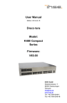
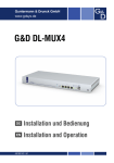
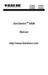
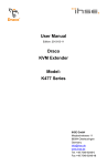
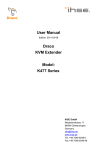
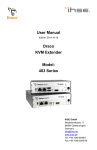
DRACO™- MINOR SWITCH
DRACO™- MINOR SWITCH
DRACO™- MINOR SWITCH
2.2
System Setup
1 Quick Setup
To install your Draco™-minor Switch system:
This section briefly describes how to install your Draco™-minor Switch system. Unless you are an
experienced user, we recommend that you follow the full procedures described in the rest of this
manual. You can download the manual at http://www.ihse.de/pdf/b459-xx_e.pdf.
1.
Switch off all devices.
2.
Connect your keyboard, monitor(s) and mouse to the Remote Unit (depending on device type).
Installation of the system
1.
2.
3.
4.
5.
6.
Draco™- minor Switch
Multifunctional device:
Usable as:
Mark the Draco™-minor Switch with the help of the provided stickers
according to your application
Set the DIP-switch according to your application
Connect Draco™-minor Switch to Local unit with CATx- cable(s).
Connect Draco™-minor Switch to Remote unit with CATx- cable(s).
Connect the devices to the power supplies.
Power up the system.
3.
Connect the CPU/signal source to the Local Unit using the supplied cable(s).
4.
Attach the connection cables (CATx- cable) between Draco™-minor switch and Local Unit and
between Draco™-minor switch and Remote Unit.
Connection options:
NO
Power LED
illuminated?
YES
• Multiplex Repeater
• Crosspoint Switch
• Single-Head KVM-Switch
• Dual-Head KVM-Switch
Check p.s.u.’s and connection to
power outlet
NO
Leuchten die
Link LEDs ?
5.
Take the Draco™-minor switch from the packing and also the sheet with the product stickers.
6.
Loosen the corresponding sticker to your application area from the sheet and stick it on the
intended place:
Check the CATx- cable, and
CATx- connectors
YES
Done
Type:
K459-7C
K459-7M
K459-7S
K459-7X
(Quick Setup)
2 Installation
For first-time users, we recommend that you carry out a test placement, confined to a single room,
before commencing full installation. This will allow you to identify and solve any cabling problems,
and experiment with the Draco™-minor System more conveniently.
2.1
Package Contents
You should receive the following items in your Draco™-minor Switch for CATx package:
•
Draco™-minor Switch
•
1x 5V DC universal power supply for the Draco™-minor Switch
•
1x serial cable RJ45 / DB9Female
•
1x German type power cord
•
1x sheet of product stickers
•
User manual (Quick Setup)
If anything is missing, please contact Technical Support.
manual: http://www.ihse.de/pdf/b459-xx_e.pdf
manual : http://www.ihse.de/pdf/b459-xx_e.pdf
manual : http://www.ihse.de/pdf/b459-xx_e.pdf
DRACO™- MINOR SWITCH
7.
Loosen the stickers below for the inscription of the interfaces and stick it on the intended place:
DRACO™- MINOR SWITCH
DRACO™- MINOR SWITCH
The use of unshielded CATx- cable is possible; because of the higher electromagnetic
noise/sensitivity the device class may not be reached.
3.1.3 Configuration ‘MR’ – 4 Sources on 4 Displays
The use of flexible cables (patch cable) type AWG26/8 is possible. Because of the higher
loss of the stranded cables, the maximum distance is reduced to app. half the value of solid
cables.
Connect to 5V power
supply
A point to point connection is required. Having one or more patch panels in the line is
possible and allowed. Not allowed is a connection from the CATx- link interface (RJ45) to
any other products, especially telecommunications or network equipment.
8.
Set the DIP-switch to the adjustment, which corresponds to your desired application. Closer
information for the DIP switch set-up can be found in the manual.
Connect to the Draco™KVM/ Media Local Units
Push-button, no function in
this operating mode
LD LC LB LA
For the connection of the Local Unit to the Draco™-minor Switch
and Remote Unit to the Draco™-minor Switch you will need the
supplied cross cables! A direct connection at EIA/TIA wiring is
NOT possible!
RD RC RB RA
Connect to the Draco™KVM/ Media Remote Units
Power Supply: Connect the supplied 5V/DC power supplies to the Plug terminal on the rear of
Draco™ Local Unit, Draco™-minor Switch or Draco™- Remote Unit.
Draco™-minor Switch – as 4x 1to4 Multiplex- Repeater
9.
Depending upon your application it can be necessary that you make a connection to a controller
over the serial interface. Attach in addition the provided RJ45 to DSUB 9-pin cable at the
socket of the serial interface and connect it with your controller. More information for control
through the serial interface can be found in the manual.
3 Geräteansichten
3.1.4 Configuration ‘Crosspoint-Switch (CPS)’ 1 Input / 7
Outputs
3.1.1 Configuration ‘Multiplex-Repeater (MR)’ – 1 Source
up to 7 Displays
Connect to 5V power
supply
Connect to 5V power
supply
Connect to the Draco™Media Local Unit
Connect to the
Draco™-Media Local
Unit
Connect to the Draco™Media Remote Units
R2 R4 R6
10. Connect the 5V power supplies to the units.
Only use the power supply originally supplied with this
equipment or a manufacturer-approved replacement.
11. For a dual access system, connect the monitor for the local console to the appropriate port on
the Local Unit. The port may also be used to feed into a KVM switch.
R
R
R
L
R
R
R
R
Push-button; for the
sequential selection of preprogrammed configurations
L
R1 R3 R5 R7
Connect to the Draco™Media Remote Units
To attach a local (USB-) keyboard/mouse, please use additional USB port(s) at your CPU or
use an USB hub in-between CPU and Local Unit’s USB- connector.
Connect to the Draco™Media Remote Units
Push-button, no function
in this operating mode
Draco™-minor Switch – as Crosspoint-Switch 1x7
12. Power up the system.
Draco™-minor Switch – as 1to7 Multiplex-Repeater
2.3
3.1.5 Configuration ‘CPS’ 2 Inputs / 6 Outputs
Interconnection Cable Requirements
To connect the Draco™-Media Local Unit to your CPU/signal source you will need (Please ensure
that the connection is tension-free!):
DVI: Connect the supplied DVI- cable 1,8m (DVI-I male to DVI-I male) to your CPU (KVMSwitch, DVI- signal source, etc.).
To connect the Draco™- KVM Local Unit to your CPU/signal source you will need (Please ensure
that the connection is tension-free!):
3.1.2 Configuration ‘MR’ – 2 Sources / each up to 3
Displays
Connect to 5V power
supply
Connect to the Draco™Media Remote Units A
To connect the Draco™- KVM Local Unit with serial/audio you will additionally need (Please
ensure that the connection is tension-free!):
Connect to the Draco™Media Local Units
R2 R4 R6
RA RA RA LA
RB RB RB LB
Push-button; for the
sequential selection of preprogrammed configurations
Connect to the Draco™Media Local Unit A
DVI: Connect the supplied DVI-cable 1,8m (DVI-I male to DVI-I male) to your CPU (KVMSwitch, DVI- signal source, etc.).
USB: Connect the supplied USB- cable 1,8m (USB Type A to USB Type B) to your CPU
(KVM- Switch, DVI- signal source, etc.).
Connect to 5V power
supply
Push-button, no
function in this
operating mode
L1
R1 R3 R5 L2
Connect to the Draco™Media Remote Units
Serial cable: Connect the supplied serial cable to your CPU/signal source.
Audio cable: Connect the supplied audio cable to your CPU.
CATx- cable: Recommended cable: S/UTP (Cat5) according EIA/TIA 56A, TSB 36 or Digital STP
17-03170. Four pairs AWG 24. Wiring according EIA/TIA 568A (10BaseT). Use of cables from a
higher category (Cat5e, Cat6, Cat7) is possible.
manual: http://www.ihse.de/pdf/b459-xx_e.pdf
Connect to the Draco™Media Remote Units B
Connect to the Draco™Media Local Unit B
Draco™-minor Switch – as Crosspoint-Switch 2x6
Draco™-minor Switch – as 2x(2to3) Multiplex-Repeater
manual : http://www.ihse.de/pdf/b459-xx_e.pdf
manual : http://www.ihse.de/pdf/b459-xx_e.pdf
DRACO™- MINOR SWITCH
3.1.6 Configuration ‘CPS’ 3 Inputs / 5 Outputs
Connect to 5V power
supply
Connect to the Draco™Media Local Units
R2 R4 L3
R1 R3 R5
Push-button; for the
sequential selection of preprogrammed configurations
DRACO™- MINOR SWITCH
DRACO™- MINOR SWITCH
3.1.9 Configuration ‘CPS’ 6 Inputs / 2 Outputs
3.1.12
Connect to 5V power
supply
Connect to the Draco™Media Local Units
R2
L1
L2
L5 L3
L1
R1 L6 L4
L2
Pushbutton; for the sequential
selection of pre-programmed
configurations
Connect to the Draco™KVM Local Units (Console) –
Video 2 + k/m
Connect to the Draco™KVM Local Units (CPU) –
Video 2 + k/m
Push-button; for the
sequential selection of
the connected CPUs
Connect to 5V power
supply
Connect to the Draco™Media Remote Units
Connect to the Draco™Media Remote Units
Configuration ‘Dual-Head KVM-Switch’
RB
LB3 LB2 LB1
RA
LA3 LA2 LA1
Connect to the Draco™KVM Remote Units
(Console) – Video 1 + k/m
Connect to the Draco™KVM Local Units (CPU) –
Video 1 + k/m
Draco™-minor Switch – as Crosspoint-Switch 6x2
Draco™-minor Switch – as Crosspoint-Switch 3x5
Draco™-minor Switch – as Dual-Head KVM-Switch
3.1.7 Configuration ‘CPS’ 4 Inputs / 4 Outputs
Connect to 5V power
supply
Connect to the Draco™Media Local Units
Pushbutton; for the sequential
selection of pre-programmed
configurations
3.1.10
Configuration ‘CPS’ 7 Inputs / 1 Output
Connect to 5V power
supply
Connect to the Draco™Media Local Units
L7
R2 R4
L3
L1
L5
R1 L6
L3
Push-button; for the
sequential selection of preprogrammed configurations
L1
L 4 L2
Operating Mode
(DIP switch)
R1 R3 L4 L2
Serial Interface
(RS232)
Draco™-minor Switch rear view
Connect to the Draco™Media Remote Unit
Connect to the Draco™Media Remote Units
Draco™-minor Switch – as Crosspoint-Switch 1x7
4 Service Setup
Draco™-minor Switch – as Crosspoint-Switch 4x4
3.1.8 Configuration ‘CPS’ 5 Inputs / 3 Outputs
Connect to 5V power
supply
Connect to the Draco™Media Local Units
Pushbutton; for the sequential
selection of pre-programmed
configurations
3.1.11
Configuration ‘Single-Head KVM-Switch’
Connect to the Draco™KVM Local Units (CPU)
Connect to 5V power
supply
Normally it is necessary to make adjustments only within the initial operation.
In order to make these adjustments, you do not have to open the Draco™-minor Switch. All settings
can be made from the outside using the Operating Mode Selector (DIP switch).
Push-button; for the
sequential selection of the
connected PCs
By pre-selecting a new operating mode the allocation of in- and
outputs may be changed. Thereby it is possible to interconnect
two transmitters. Damage cannot be excluded.
For the selection of a new operating mode:
R2 L5
L3
R1 R3 L4
L1
L2
Connect to the Draco™Media Remote Units
L7
R
Connect to the Draco™KVM Remote Unit (Console)
L5
L6
L3
L4
L1
L2
Connect to the Draco™KVM Local Units (CPU)
1.
Switch off the Draco™-minor Switch.
2.
Select a new operating mode according to following table.
By pre-selecting a new operating mode the allocation of in- and
outputs may be changed. Thereby it is possible to interconnect
two transmitters. Damage cannot be excluded.
3.
Power up the device.
Draco™-minor Switch – as Crosspoint-Switch 5x3
Draco™-minor Switch – as Single-Head KVM-Switch
manual: http://www.ihse.de/pdf/b459-xx_e.pdf
manual : http://www.ihse.de/pdf/b459-xx_e.pdf
manual : http://www.ihse.de/pdf/b459-xx_e.pdf
DRACO™- MINOR SWITCH
DRACO™- MINOR SWITCH
4.1.1 Operating Mode Pre-selection
5.
set the DIP- switch back
Operating Mode Switch
6.
switch power on - done
DRACO™- MINOR SWITCH
Are there errors through data transmission over CATx- cable (cable too long, too high
attenuation or too much EMI interferences)? Is the Data Error LED illuminated or
blinking? If yes, check cable length and environment.
Operating Mode after Reset/ Power ON: After reset the respective
DEFAULT-mode is selected.
Operating Mode after Reset/ Power ON: After reset the previous
mode before reset or power off is selected.
Switch setting
Down
Operating Mode
Switch
Switch setting
Up
Switch setting
Extraneous
Master: In a cascaded application as KVM- switch the device is
‘Master’– i.e. it is on highest level within the tree structure, seen from
the Remote Unit.
Slave: In a cascaded application as KVM- switch the device is ‘Slave’–
i.e. it is on second level within the tree structure, seen from the Remote
Unit.
Operating Mode
Multiplex- Repeater: The signal(s) coming from the Local Unit is
(are) straightened (and distributed) and extended over further 140m.
•
An incoming DVI
(+audio) signal is
distributed and
extended on up to 7
outputs.
An incoming DVI
(+audio) signal is
distributed and
extended on up to 7
outputs.
Crosspoint Switch: Every port can be either an input (to a Local Unit)
or an output (to a Remote Unit). Each connection input/output is
possible.
„Juddering“ pictures at video presentations
Due to the high monitor resolutions the data volume that can be transferred exceeds the
available bandwidth by far, so the data must be reduced. For this a RLE compression
algorithm is used at first. If the necessary compression factor is not reached, not all
pictures of the graphic card are transferred (frame dropping). That is the reason why the
video presentation may begin to „judder“.
Hint: Use a lower resolution, which is a little larger than the resolution of the stored film
material. If the monitor has a higher resolution, then this can take over the scaling of the
video data. For the image quality it is irrelevant whether the scaling is done via the CPU or
via the monitor.
5 Diagnostic
An incoming DVI
(+audio) signal is
distributed and
extended on up to 7
outputs.
Video Okay LED is dark: CPU does not provide a video signal – Check settings of the
graphic card. Try out, connecting a monitor to the local output, to see, whether there is a
signal or not.
Each Draco™-minor Switch is fitted with two indicator LEDs: Power and Link Status: The Power
LED is next to the Power socket. The Link Status LEDs are at the upper CATx- connectors in the
left and right upper corner. The LEDs in the left corners show the status for the lower CATxconnectors, the right LEDs for the upper CATx- connectors.
Hint: Set the colour depth to 16 bits. Usually the human eye is not able to differentiate
between so many different colours with moving pictures. A reduction on 16 bits makes the
data volume that has to be transferred smaller without loss of image quality.
6.1.2 USB- Keyboard/ Mouse
The location of the LEDs is shown below:
Your USB-keyboard/USB-mouse does not work
Although we tried to design the devices as transparent as possible, we can’t ensure that all
devices are running. Please check the list of supported devices.
Your USB- Mouse makes ” jerky leaps”
1x IN / 7x OUT
The signals of one
source can be
switched up to 7
displays.
1x IN / 7x OUT
The signals of one
source can be
switched up to 7
displays.
Due to the high monitor resolutions the data volume that can be transferred exceeds the
available bandwidth by far, so the data must be reduced. For this a RLE compression
algorithm is used at first. If the necessary compression factor is not reached, not all
pictures of the graphic card are transferred (frame dropping). Thus the mouse may make
jerky leaps.
1x IN / 7x OUT
The signals of one
source can be
switched up to 7
displays.
Diagnostic LED
Power
4x IN / 4x OUT
The signals of 4
sources can be
switched up to 4
displays.
4x IN / 4x OUT
The signals of 4
sources can be
switched up to 4
displays.
4x IN / 4x OUT
The signals of 4
sources can be
switched up to 4
displays.
Diagnostic LED
Link Status
Lower connector
Diagnostic LED
Link Status
Upper connector
Hint: Use a lower resolution or a background which can be compressed better: Please
avoid photo-backgrounds or colour gradient – single-coloured backgrounds are optimal
and permit highest possible compression rates => highest frame rates.
Your USB- Mouse moves like on a “rubber band“
Diagnostic- LEDs at Draco™-minor Switch for CATx
LED
Appearance
Diagnostics
Power LED
(Red LED)
Off
On
Device not ready
Device ready
Link Status
(Orange LED)
Off
blinking
On
No transmission over the CATx- cable
active connection (only type KVM- Switch)
Connection OK
This problem consists of several one-time jobs, which lead to a whole time delay between
mouse movement and display on the screen. After our measurements time delays of more
than 100 ms are bothering.
The total delay consists of (numerical data are approx. values):
7x IN / 1x OUT
The signals of 7
sources can be
switched up to one
display.
KVM- Switch 1/7 Single-Head : Up to 7 CPUs can be operated from
one console (up to 49 with cascaded application).
6 Troubleshooting
KVM- Switch 1/3 Dual-Head : Up to 3 CPUs with Dual-Head
graphic card can be operated from one console (up to 9 with cascaded
application).
6.1.1 Monitor
Standard operating mode
Reset the Draco™-minor Switch to default settings (Factory Reset):
1.
switch power off
2.
set the DIP- switch
3.
switch power on, the device is resetting
4.
switch power off
manual: http://www.ihse.de/pdf/b459-xx_e.pdf
There isn’t a picture.
Check the power supply connection at the Local and Remote Unit. Is the Power LED at
the Local and Remote Unit illuminated? If not, the internal power supply may be damaged
or there may be an internal error.
Check that the interconnection cable is connected at the Local Unit and the Remote Unit.
Is the Link Status LED illuminated? If not, there may be a problem with the
interconnection cable:
manual : http://www.ihse.de/pdf/b459-xx_e.pdf
•
5 ms mouse movement/ transmission to the CPU
•
25 – 40 ms processing time in the CPU, until data change at the graphic output
appears
•
15 – 50 ms assumption of the graphic data into the extender-system and
transmission to remote unit
•
15 – 100 ms processing time in the screen until data are indicated
The majority of the resulting response times between 60 and 200 ms are not a consequence
of the extender-system. However, our studies show that already a step from 80ms to
110ms that can take place by inserting an extender-system is bothering.
Hint: Use a display with a shorter response time (please note: this time does not have to
agree under any circumstances with the response time indicated by the manufacturer,
which only means how quickly two successive pictures can be displayed, not however,
how long it lasts until a signal of the input interface needs to the screen). Use a lower
resolution or a background which can be compressed better: Please avoid photobackgrounds or colour gradient – single-coloured backgrounds are optimal and permit
highest possible compression rates.
manual : http://www.ihse.de/pdf/b459-xx_e.pdf