1
2
<<Contents>> <<Index>>
Overview display:
18 channels max. (including computation
channels) for measurement
Measured values and alarms for all channels.
Information display:
Jumps to the trend view of a data item
selected by the cursor.
Alarm summary display: Display the list of alarms.
Event summary display:
Display the list of events.
Control operation summary screen:
Display the list of control operation
statuses.
Message summary display:
Display the list of message and time.
Memory summary display:
Display the list of internal memory.
Tag display: Tag names for measurement channels (up
to 16 alphanumeric characters)
Tag names for control loops and DIO
(up to 8 alphanumeric characters)
Tag comments for control loops and DIO
(up to 8 alphanumeric characters)
Other on-display elements:
Memory status, scale values (0%, 100% can be turned on/off), scales (6 scales
max.), grid (selectable from a range of 4 to
12 divisions) with hour:min indications, date
and time (year/month/day and
hour:minute:second indications), trip line
(selectable from 1-, 2- and 3-pixel thickness
options), messages (of up to 16 characters
and 8 types), and alarm marks
Data reference function:
Display the retrieved data.
Display format: Bisectional or full-screen view
Time axis: Can be upscaled, downscaled, and
scrolled.
Automatic screen switching
Switching interval
5 sec, 10 sec, 20 sec, 30 sec, or 1 min
LCD back light saver function
Timer setpoint: 1, 2, 5, 10, 20 or 60 min
■ CONTROL FUNCTIONS
Control mode
Singleloop, cascade control, and loop control with PV
switching.
Control computation functions
Continuous PID control, Relay on/off control, time
proportional PID control
PID parameter: 8 sets/loop for each control mode
Points of zone PID switching: 6 max.
“Super” function (overshoot prevention)
Tracking functions: SP tracking PV tracking
Anti-reset windup function
(over-integration prevention function)
Control interval: 250, 500 or 1000 ms
All Rights Reserved. Copyright © 2001, Yokogawa Electric Corporation
Operation mode switching
• Switching among remote, local, and program modes
• Switching among manual, auto, and cascade modes
• Run/stop mode switching
Stop mode: Outputs the preset output value.
• Switching between Execute/Stop options of auto-tuning
Principle of auto-tuning: Limit cycle method
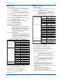
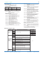
PID Control Method
PID
Control
mode
Operation
mode
Operating status
Standard Fixed point
PID control control
operation
mode
Local and cascade
control except cascade
secondary loop control
Remote or secondary
cascade loop control
Programmed
Local and cascade
control
control except
operation secondary cascade loop
control, hold or soak
During programmed
operation (without status
of hold or soak) or
secondary cascade loop
control
Fixed point Fixed point
Local and cascade
control
Control
control except cascade
operation
Mode
secondary loop control
Remote or cascade
secondary cascade loop
control
Programmed
Local, hold and soak
control
Programmed operation
operation
(without status of hold)
or secondary cascade
loop control
PID control
method
Bump of
control
output
PV derivative type
PID
Yes
Deviation derivative
type PID
PV derivative type
PID
Yes
Deviation derivative
type PID
Yes
PV derivative type PID
Yes
PV derivative type
PID
Yes
PV derivative type PID
PV derivative type
PID
No
Yes
Yes
*The secondary cascade loop is secondary loop of cascade control that is
selected from the cascade mode (auto, manual, cascade)
Setting ranges of control parameters
Proportional band: 0.1 to 999.9%
Integral time: 1 to 6000 sec, or off (for manual reset)
Derivative time: 1 to 6000 sec, or off
On-off control hysteresis wideth:
0.0 to 100.0% of measurement range
Preset output value: –5.0 to 105.0% of output
(Provided in case of control computation
being stopped, PV input being in a burnout
state, or instrument input being abnormal)
Output limiter:
Setting range: –5.0 to 105.0% for both high/low limits
Shutdown function:
Can provide a manipulated output of up to 0
mA when in manual mode operation with
4-20 mA output (shuts down the output for
values smaller than –5.1%).
Output rate-of-change limiter:
Off, or a value from 0.1 to 100.0%/sec
GS 04L31A01-01E
7th Edition Jun.01,2010-00