1
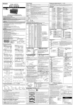
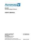
<<Contents>> <<Index>>
General
Specifications
FX100
GS 04L20A01-00E
■ OVERVIEW
FX100 displays real-time measurement data on TFT color
LCD and saves the data in external media (3.5” FD or
Flash memory card) or FTP server. It comes with a
three, six or twelve-channel. As the input signal, a DC
voltage, thermocouple, resistance temperature detector,
or contact signal can be set to each channel.
■ Standard Specifications
Construction
Dimensions: 144(W) ⫻ 144(H) ⫻ 234(D) mm
Weight:
FX1xx–0: 2.2 kg
FX1xx–1: 2.5 kg
FX1xx–4: 2.3 kg
Front panel: Water and dust-proof (based on IEC529IP65)
Inputs
Number of inputs:
FX103: 3 channels
FX106: 6 channels
FX112: 12 channels
Measurement interval:
FX103: 250 ms
FX106, FX112: 1 s/2 s
Inputs:
VDC (DC voltage), TC (thermocouple), RTD
(resistance temperature detector), DI (digital
input for event recording), DCA (DC current
with external shunt resistor attached)
Input Ranges and Measuring Ranges
Input Type
DCV
Input Range
Measuring Range
20 mV
–20.00 to 20.00 mV
60 mV
–60.00 to 60.00 mV
200 mV
–200.0 to 200.0 mV
2V
–2.000 to 2.000 V
6V
–6.000 to 6.000 V
20 V
–20.00 to 20.00 V
50 V
TC
RTD *5
0.0 to 1760.0°C
32 to 3200.0°F
S *1
0.0 to 1760.0°C
32 to 3200.0°F
B *1
0.0 to 1820.0°C
32 to 3308.0°F
K *1
–200.0 to 1370.0°C
–328 to 2498.0°F
E *1
–200.0 to 800.0°C
–328.0 to 1472.0°F
J *1
–200.0 to 1100.0°C –328.0 to 2012.0°F
T *1
–200.0 to 400.0°C
N *1
0.0 to 1300.0°C
32 to 2372.0°F
W *2
0.0 to 2315.0°C
–328.0 to 4199.0°F
L *3
–200.0 to 900.0°C
–328.0 to 1652.0°F
U *3
–200.0 to 400.0°C
–328.0 to 752.0°F
WRe*5
0.0 to 2400.0°C
32 to 4352.0°F
Pt100 *4
–200.0 to 600.0°C
–328.0 to 1112.0°F
JPt100 *4
–200.0 to 550.0°C
–328.0 to 1022.0°F
Pt1000 (Option)*6
–200.0 to 600.0°C
–328.0 to 1112.0°F
DCV Input
DI
–50.00 to 50.00 V
R *1
Contact Inputs
–328.0 to 752.0°F
OFF: Less than 2.4 V, ON: More than 2.4 V
Contact Input ON/OFF
*1: R, S, B, K, E, J, T, N: IEC584-1(1995), DIN IEC584, JIS C1602-1995
*2: W: W–5% Re/W–26% Re (Hoskins Mfg. Co.), ASTM E988
*3: L: Fe-CuNi, DIN43710, U: Cu-CuNi, DIN43710
*4: Pt100: JIS C1604-1997, IEC751-1995, DIN IEC751-1996,
JPt100: JIS C1604-1989, JIS C1606-1989,
Measuring current: i=1 mA
*5: WRe: W–5% Re/W–25% Re (Hoskins Mfg. Co.)
*6: Measuring current: i=0.16 mA
GS 04L20A01-00E
©Copyright Oct., 2003
1st Edition Oct., 2003
2
<<Contents>> <<Index>>
Inputs terminal: Clamp terminals (clamp connector),
detachable terminal connector
Allowable wire size: 0.2 to 2.5 mm2 (AWG24-12)
Integral time of A/D converter:
20 ms (50 Hz), 16.7 ms (60 Hz), 100 ms
(50/60 Hz, for FX106 and FX112)
AUTO selectable (automatic selection by
detection of power supply frequency from
20 ms, 16.7 ms)
Themoccouple Burnout:
Burnout upscale/downscale function can be
switched on/off (for each channel).
Burnout upscale/downscale selectable
Burnout condition:
Normal: less than 2 k⍀
Burnout: more than 100 k⍀
Filter function:
FX103:
On/off selectable for each channel
Time constant: selectable from 2, 5, and10
seconds
FX106, FX112: Moving average on/off selectable for
each channel, moving average cycles 2 to
16 selectable
Calculation: Differential computation, linear scaling,
square root
Display
Display unit: 5.5-inch TFT color LCD (320 ⫻ 240 pixels)
Waveform span rate:
FX103:
15, 30 sec., 1, 2, 5, 10, 15, 20, 30 min., 1, 2,
4, 10 hours/div selectable
FX106, FX112:
1, 2, 5, 10, 15, 20, 30 min., 1, 2, 4, 10
hours/div selectable
LCD back light saver function:
Automatically dims if no key is touched for a
certain preset time
Timer setpoint:
1, 2, 5, 10, 30 or 60 min
Temperature unit:
°C or °F selectable
Language: English, French and German selectable
Data Saving Function
Internal memory:
Flash memory (1.2M)
External storage medium:
Selectable from: 1) None
2) 3.5-inch floppy disk
(2HD, 1.44 MB)
3) Compact flash memory card
(32 to 512 MB)
Saving method: Manual or automatic selectable
Measurement data files:
Display data and event data
Data saving period:
Display data file:
Linked with the waveform span rate
Event file: Linked with the specified sampling period
Event File sampling period:
FX103: Selectable from 250, 500 ms, and 1, 2, 5,
10, 30, 60, 120, 300, 600 s
FX106, FX112:
Selectable from 1, 2, 5, 10, 30, 60, 120,
300, and 600 s
All Rights Reserved. Copyright © 2003, Yokogawa Electric Corporation
Alarm Function
Number of alarm levels:
Up to four levels for each channel
Alarm types:High and low limits, differential high and low
limits, high and low rate-of-change limits
and delay high and low
Interval time of rate-of-change alarms:
The measurement interval times 1 to 15
Display:
The alarm status (type) is displayed in the
digital value display area upon occurrence
of an alarm. A common alarm indication is
also displayed.
The alarming behavior:
Non-hold or hold-type can be selectable for
common to all channels.
Hysteresis: On (0.5% of display span) /off selectable
(common to all channels and alarm levels)
Outputs:
Number of points: 2, 4, or 6 points (optional)
Relay action:Energized/deenergized and hold/non-hold
selectable.
Memory:
The times of alarm occurrences/recoveries,
alarm types, etc. are stored in the memory.
(Up to 120 latest alarm events are stored.)
Normal Operating Conditions
Ambient temperature:
0 to 50°C (when using FDD: 0 to 40°C)
Ambient humidity:
20% to 80% RH (at 0 to 40°C)
10% to 50 % RH (at 40 to 50°C)
Vibration: 10 to 60 Hz, 0.2 m/s2 or less
Shock:
Not acceptable
Magnetic field: 400 AT/m or less (DC and 50/60 Hz)
Noise:
Normal mode (50/60 Hz):
VDC: The peak value including the signal must
be less than 1.2 times the measuring
range.
TC:
The peak value including the signal must
be less than 1.2 times the measuring
thermal electromotive force.
RTD: 100 mV or less
Common mode noise voltage (50/60 Hz):
250 V AC rms or less for all ranges
Maximum noise voltage between channels (50/60 Hz):
250 V AC rms or less
Warm-up time: At least 30 min after power on
Transport and Storage Conditions
Ambient temperature:
–25°C to 60°C
Humidity:
5% to 95% RH (No condensation is
allowed)
Vibration: 10 to 60 Hz, 4.9 m/s2 maximum
Shock:
392 m/s2 maximum (while being packed)
Safety and EMC Standards
Safety standards:
CSA22.2 No.1010-1, UL61010B-B (CSA
NRTL/C)
EN61010-1
EMC standard:
EN61326
EN55011 Class A
EN61000-3-2
EN61000-3-3
GS 04L20A01-00E
1st Edition Oct.10,2003-00
3
<<Contents>> <<Index>>
Power Supply
Rated power supply:
100 to 240 VAC (automatic switching)
Allowable power supply voltage range:
90 to 132 or 180 to 264 VAC
Rated power supply frequency:
50/60 Hz (automatic switching)
Power consumption:
Supply voltage LCD save mode
Normal
Max.
100 VAC
10 VA
14 VA
25 VA
240 VAC
18 VA
22 VA
35 VA
Dielectric strength:
Power supply to ground terminal:
2300 VAC (50/60 Hz), 1 min
Contact output terminal to ground terminal:
1600 VAC (50/60 Hz), 1 min
Measuring input terminal to ground terminal:
1500 VAC (50/60 Hz), 1 min
Between measuring input terminals:
1000 VAC (50/60 Hz), 1 min (except for b
terminal of RTD input of non-isolated)
Between remote control terminal to ground terminal:
1000 VDC, 1 min
Pulse input terminal to ground terminal:
1000 VDC, 1 min
Insulation resistance:
Each terminal to ground terminal:
20 MV or greater (at 500 VDC)
Standard Performance
Measuring and Recording Accuracy:
The following specifications apply to operation of the recorder under standard operation conditions.
Temperature:
23±2°C, Humidity : 55% ±10% RH, Power supply voltage : 90 to 132 or 180 to 250 VAC,
Power supply frequency:
50/60 Hz ±1%, Warm-up time : At least 30 min.
Other ambient conditions such as vibration should not adversely affect recorder operation.
Input Type
DC voltage
(DCV)
Range
20 mV
60 mV
200 mV
2V
6V
20 V
50V
R
S
B
Thermocouple
(TC)- Excluding the
reference junction
compensation
accuracy)
RTD
K
E
J
T
N
W
L
U
WRe
Pt100
JPt100
Pt1000
(option)
Measurement accuracy (digital display)
± (0.1% of rdg + 2digits)
± (0.1% of rdg + 3digits)
±(0.15% of rdg + 1°C)
However, R, S: ±3.7°C at 0 to 100°C,
±1.5°C at 100 to 300°C
B: ±2°C at 400 to 600°C
(Accuracy at less than 400°C is not guaranteed.)
±(0.15% of rdg + 0.7°C)
However, ±(0.15% of rdg + 1°C) at –200 to –100°C
±(0.15% of rdg + 0.5°C)
However,
±(0.15% of rdg + 0.7°C) at -200 to -100°C
±(0.15% of rdg + 0.7°C)
±(0.15% of rdg + 1°C)
±(0.15% of rdg + 0.5°C)
However, ±(0.15% of rdg + 0.7°C) at –200 to –100°C
±(0.2% of rdg + 1.0°C)
Max. resolution of
digital display
10µV
10µV
100µV
1 mV
1 mV
10 mV
10 mV
0.1°C
±(0.15% of rdg + 0.3°C)
±(0.2% of rdg + 0.4°C)
All Rights Reserved. Copyright © 2003, Yokogawa Electric Corporation
GS 04L20A01-00E
1st Edition Oct.10,2003-00
4
<<Contents>> <<Index>>
Measurement accuracy in case of scaling (digits):
= measurement accuracy (digits) ⫻ scaling
span (digits)/measurement span (digits) + 2
digits
Decimals are rounded off to the next highest number.
Reference junction compensation:
INT (internal)/EXT (external) selectable
(common for all channels)
Reference junction compensation accuracy
(above 0°C, in balance of input terminal
temperature: more than 60 minutes after
application of power):
Types R, S, B, W, WRe: ±1.0°C
Types K, J, E, T, N, L, U: ±0.5°C
Note: Internal reference junction compensation accuracy
for type B is fixed to 0 °C
Maximum allowable input voltage:
±10 VDC (continuous) for less than
200mVDC ranges and TC, RTD, DI ranges
±60 VDC (continuous) for except above
ranges
Input resistance:
Approximately 10 M⍀ or more for DCV
ranges of 200 mVDC or less and TC
Approximately 1 M⍀ for more than 2 VDC
ranges
Input source resistance:
VDC, TC: 2 k⍀ or less
RTD: 10 ⍀ or less per wire (The resistance
of all three wires must be equal.)
RTD parallel capacity:
0.01 µF or less
Input bias current:
10 nA or less
Maximum common mode noise voltage:
250 VAC rms (50/60 Hz)
Maximum noise voltage between channels:
250 VAC rms (50/60 Hz)
Interference between channels:
120 dB (the input source resistance: 500 ⍀
the inputs to other channels: 30 V)
Common mode rejection ratio:
120 dB (50/60 Hz ± 0.1%, 500 ⍀ imbalance
between the minus terminal and ground)
Normal mode rejection ratio:
40 dB (50/60 Hz ± 0.1%)
Input source resistance: With variation of +1 k⍀
(1) VDC range:
Ranges of 200 mV or less: within ±10 µV
Ranges of 2 V or greater:
approximately ±0.1% of rdg
(2) TC range: Within ±10 µV (±100 µV when the
burnout upscale/downscale function is
switched on)
(3) RTD range (Pt100):
With variation of 10 ⍀ per wire (resistance
of all three wires must be equal): ±(0.1% of
rdg + 1 digit)
With maximum difference of 40 m⍀ between wires:
Approximately 0.1°C
Other Specifications
Clock:
With calendar function (year of grace)
The time can be adjusted by a remote
contact (with the remote option).
Summer/winter time:
Summer and wintertime can be set.
Accuracy of clock:
±100 ppm, excluding a delay (of 1 second,
maximum) caused each time the power is
turned on.
Memory backup:
A built-in lithium battery backs up the setup
parameters (battery life: approximately ten
years at room temperature).
Key lock function:
ON/OFF and password can be set.
Log in function:
Power on with log out mode and all key
operations are not permitted.
“User name”, “User ID” and “password” are
required to enter the operation mode.
And key lock by password can be set to
prevent to change settings.
Effects on Operating Conditions
Ambient temperature: With temperature variation of 10°C
For VDC and TC range:
±(0.1% of rdg + 1 digit) or less
For RTD inputs:
±(0.1% of rdg + 2 digits) or less
Power supply: With variation within 90 to 132 V and 180
to 250 VAC (50/60 Hz):
±1 digit or less
With variation of ±2 Hz from rated power
frequency (at 100 VAC): ±(0.1% of rdg + 1
digit) or less
Magnetic field: AC (50/60 Hz) and DC 400 A/m fields:
±(0.1% of rdg + 10 digits) or less
All Rights Reserved. Copyright © 2003, Yokogawa Electric Corporation
GS 04L20A01-00E
1st Edition Oct.10,2003-00
5
<<Contents>> <<Index>>
■ SPECIFICATIONS OF OPTIONAL
FUNCTIONS
Alarm Output Relays (/A1, /A2, /A3):
Outputs:
Number of outputs: 2, 4, 6 points
An alarm signal is output from the rear panel as a relay
contact signal.
Relay contact rating:
250 VDC/0.1 A (for resistance load) 250
VAC (50/60 Hz)/3 A
Terminal configuration:
SPDT (NO-C-NC). Energized-at-alarm/
deenergized-at-alarm, AND/OR, and hold/
non-hold actions are selectable.
Serial Communication Interface (/C2, /C3):
Allows the host computer to control and make settings
for the recorder as well as receive data from the
recorder.
Connection: EIA RS-232 (/C2) or RS-422-A/485 (/C3)
Protocols: YOKOGAWA private protocol, Modbus
protocol
Synchronization method:
Start-stop asynchronous transmission
Connection method (RS-422-A/485):
4-wire half-duplex multi-drop connection
(1: N where N = 1 to 32)
Transmission speed:
1200, 2400, 4800, 9600, 19200 or 38400
bps
Data length: 7 or 8 bits
Stop bit:
1 bit
Parity:
Odd, even, or none
Communication distance (RS-422-A/485):
Up to 1.2 km
Communication mode:
ASCII for input/output for control and setting
ASCII or binary for output of measured data
Modbus communication:
Operation mode: RTU MASTER or RTU SLAVE
Ethernet Communication (/C7)
Connection: Ethernet (10BASE-T)
Protocols: SMTP, HTTP1.0, FTP, TCP, UDP, IP, ARP,
ICMP
E-mail inform function:
Kinds of inform:
The following information can be informed
by E-mail, selectable from inform/misinform
for each group
Alarm inform:
Informs in occurring alarm/canceling alarm
System inform:
Informs in recovering power failure/informs
the time of recovering, informs the rest of
time before rewriting on Inside memory
(manual save mode) informs the rest of
amount in reaching 90% of media volume
and media error (auto save mode)
Schedule time inform: Inform the moment value at a
certain time or interval
Report inform: Inform report data in report timeup
All Rights Reserved. Copyright © 2003, Yokogawa Electric Corporation
Web server function:
Displays an image, alarm information, and
moment values of FX screen by browser
soft.
Enables message input from browser
screen.
FTP client function:
File auto-transfer from FX (display data file,
event file, report file, and snapshot)
FTP server function:
Manual-transfer of file in the outside media
from host computer, directory operation,
information of file elimination and of rest of
amount of memory in media
Real time monitoring function:
Real time monitoring FX data by
communication (Yokogawa private protocol)
Fail/Memory End Output (/F1):
The relay contact output in following cases
System Error: Relay output in occurrence of system
alarm
Manual save mode:
Relay output before the specified time of
overwriting inside memory
Selectable from 1, 2, 5, 10, 20, 50, or 100
hours
Auto save mode:
Relay output when the amount of memory
media reaches 90%
Relay contact rating:
250 VDC/0.1 A (for resistance load) 250
VAC (50/60 Hz)/3 A
Mathematical Functions (/M1):
Displays and records computed data assigned to
channels
Number of computed data assignable channels:
Up to 12 channels
Type of computation:
General arithmetic operations:
Four arithmetic operations, square root,
absolute, common logarithm, exponential,
power, relational operations (⬍, ⬉, ⬎, ⭌, ⫽,
≠), logic operations (AND, OR, NOT, XOR)
Statistical operations:
Average, maximum, minimum and
summation
Long tern rolling average computation:
is performed on the results of computation
Constant: Available (Up to 30 constants)
Digital data input via communication:
Digital data via communication can be used
in mathematical expression (Up to 12 data)
Remote status input:
Remote input status (0/1) can be used in
mathematical expression (Up to 8 inputs)
Report functions:
Report type: Hourly, daily, hourly + daily,
daily + weekly and daily + monthly
Type of computation:
Average, maximum, minimum and
summation
Data format: ASCII
GS 04L20A01-00E
1st Edition Oct.10,2003-00
6
<<Contents>> <<Index>>
3 legs Isolated RTD Input (/N2):
A, B, b legs are of isolated input type.
/N2 can be specified only for FX106 and FX112.
A, B, b legs of FX103 is isolated as standard.
Pt1000 input (/N3):
Measuring ranges, measurement accuracy, and
resolution of digital display:
See table of Input and standard performance.
Pulse input mathematic function (/PM1)
Number of inputs:
3 points (8 points are available in case of
using remote inputs)
Max. sampling pulse period:
Max.100 Hz
Minimum pulse length:
5 ms
Allowed input voltage:
30 VDC
Pulse measuring accuracy:
±1pulse (for instantaneous mode)
Measuring mode:
Instantaneous mode setting:
Pulse count during measuring period
Summation mode setting:
Pulse count summation by mathematical
function (TLOG.SUM)
Remote Control (/R1):
Number of remote inputs: 8 points
This option allows the following eight functions to be
controlled remotely by a contact input:
• Start/stop of memory (level)
• Trigger for event file (trigger, 250 ms or longer)
• Time adjustment (adjusting the time to a preset time
upon contact signal, trigger, 250 ms or longer)
• Start/stop of computation (level)
• Reset of computation data (trigger, 250 ms or longer)
• Manual data sample (trigger, 250 ms or longer)
• Message display (Up to 8 different messages can be
set, trigger, 250 ms or longer)
• Load of setting parameters *(Up to 3 settings can be
set, trigger, and 250 ms or longer except for nonmedia model)
• Alarm acknowledgement (trigger, 250 ms or longer)
• Snapshot (trigger, 250 ms or longer)
■ APPLICATION SOFTWARE
DAQSTANDARD
Operating environment
OS:
Microsoft Windows 98/Me/NT4.0/2000/XP
Basic function (packages):
Configuration software:
External memory medium: configuration of
setup and set mode
Configuration via communication:
configuration of setup and set mode without
communication configuration (ex. address)
Data viewer:
Numbers of display channels:
32 channels for each group, at most 30
groups
Display function:
Waveform display, digital display, circular
display, list display, TLOG display, report
display etc.
File connection display:
Connect data files that are divided by autosave during measuring data or power failure
(can connect up to total a million)
Section computation:
Max. value, Min. value, average value,
effective value, p-p value
Data conversion:
File conversion to ASCII, Lotus 1-2-3 or MSExcel format
Print out: Print out retrieved data
*: Load of setting parameters is not be available for nonmedia model.
All Rights Reserved. Copyright © 2003, Yokogawa Electric Corporation
GS 04L20A01-00E
1st Edition Oct.10,2003-00
7
<<Contents>> <<Index>>
■ Model Code
Model
Suffix code
Optioncode
Description
FX103
FX100 (3ch)
FX106
FX100 (6ch)
FX112
External memory
FX100 (12ch)
–0
None
–1
FDD (3.5 inch, 1.44MB)
–4
Compact flash memory card (32MB)
–2
Display Language
Option
English (German/French)
/A1
Alarm output 2 points *1
/A2
Alarm output 4 points *1
/A3
Alarm output 6 points *1
/C2
RS-232 communication interface (including Modbus master/slave protocol function) *2*3
/C3
RS-422-A/485 communication interface (including Modbus master/slave protocol function) *2*3
/C7
Ethernet (10BASE-T) communication interface
/F1
FAIL/memory end output *4
/M1
Mathematical function (with report function)
/N2
3 legs isolated RTD
/N3
Pt1000Ω input
/PM1
Pulse input 3 points, control input 5 points (including Mathematical function ) *5
/R1
Remote control 8 points
*1: /A1, /A2, /A3 cannot be specified together.
*2: /C2, /C3 cannot be specified together.
*3: In case that Modbus master function is utilized, /M1 or /PM1 must be specified.
*4: If /F1 is specified, /A3 cannot be specified.
*5: If /PM1 is specified, each /A3, /R1, /M1 cannot be specified.
*5: If /PM1 is specified, /A2 and /F1 cannot be specified together.
■ Application Software
Model code
Description
FXA100-01 DAQSTANDARD
■ Optional Accessories
Product
OS
Model
Windows 98/Me/NT4.0/2000/XP
Shunt resister (Clamp module)
■ Standard Accessories
Product
Quantity
Mounting brackets
2
d
Terminal screw
3
Operation Manual
1
User’s Manual, CD-ROM
1
DAQSTANDARD, CD-ROM
1 *1
CF card, 32 MB
1 *2
CF card
Mounting bracket
Specification
4389 20
250Ω ± 0.1%
4389 21
100Ω ± 0.1%
4389 22
10Ω ± 0.1%
B9968NM
32 MB
B9968NP
64 MB
B9968NQ
128 MB
B9968NR
256MB
B9968NS
512MB
B9900BX
–
*1: For a model with no communication port and no external
memory, DAQSTANDARD is not attatched.
*2: Only for FX1xx-4 model
All Rights Reserved. Copyright © 2003, Yokogawa Electric Corporation
GS 04L20A01-00E
1st Edition Oct.10,2003-00
8
<<Contents>> <<Index>>
MODEL
STYLE
SUFFIX
SUPPLY
FREQUENCY
NO.
RS-422A/485
10Base-T
FG
SG
SDB
SDA
RDB
RDA
■ Dimensions
(0.95)
24.1
151.5 (5.96)
144.3 (5.68)
Unit : mm
(approx. inch)
(2.30)
58.4
175 (6.89)
9.4 (0.37)
(min. space for mounting)
(5.37)
136.5
+0.4
0
151.5 (5.96)
144.3 (5.68)
2 to 26 (panel thickness)
7.5 (0.30)
(dimension after mounting)
RS-232 or RS-422A/485
Ethernet
Power Supply
Terminal
Option Terminal
Input Terminal
1 to 12ch
The TCP/IP software used in this product and the document for that TCP/IP software are based in part on
BSD networking software, Release 1 licensed from The Regents of the University of California.
•
•
•
•
•
Microsoft, MS and Windows are registered trademarks of Microsoft Corporation USA.
Lotus and 1-2-3 are registered trademark of Lotus Development Corporation.
Ethernet is a registered trademark of XEROX Corporation.
Modbus is a registered trademark of AEG Schneider.
Other company and/or product names are registered trade mark of their manufactures.
All Rights Reserved. Copyright © 2003, Yokogawa Electric Corporation
GS 04L20A01-00E
1st Edition Oct.10,2003-00