1
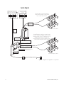
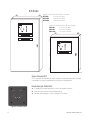
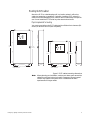
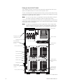
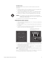
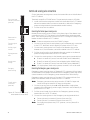
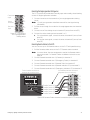
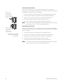
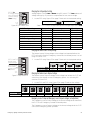
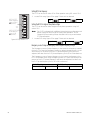
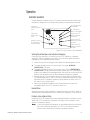
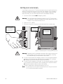
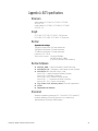
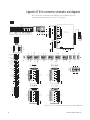
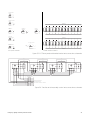
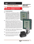
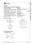
ELTS
Normal
Load
Emergency
Emergency Lighting Transfer System
(Group 1 Controller)
User Manual
2
Electronic Theatre Controls, Inc.
Contents
Introduction................................................................................................... 5
How to use this manual ........................................................................... 5
Codes and standards................................................................................ 5
System Diagram....................................................................................... 6
Installation and setup chapters
Installation..................................................................................................... 7
Unpack and Inspect.................................................................................. 7
ELTS Models............................................................................................ 8
Mounting the ELTS cabinet...................................................................... 9
Installing Remote stations (optional) ...................................................... 11
Connecting power and control wiring to the ELTS cabinet ................... 12
Connecting Emergency power (standard systems) ............................... 12
Connecting Emergency power (Discrete systems)................................ 13
Connecting lighting circuit wires to transfer switches ........................... 14
Control and sensing wire connections ................................................... 16
Testing ......................................................................................................... 19
Before you power up for the first time .................................................. 19
Turn on system ...................................................................................... 19
Functional checkout ............................................................................... 20
ELTS Timing, Voltage, and Line settings ................................................. 22
Changing ELTS settings ......................................................................... 23
Changing the Voltage Adjust setting...................................................... 25
Use and service chapters
Operation..................................................................................................... 27
Automatic operation............................................................................... 27
Switching power sources manually ....................................................... 28
Service ......................................................................................................... 30
Preventive maintenance......................................................................... 30
Troubleshooting ......................................................................................... 31
Emergency or Normal Power Stable LED does not turn on properly..... 31
The ELTS will not switch between Normal and Emergency.................. 31
Remote stations cannot switch the ELTS.............................................. 32
Appendices
Appendix A: ELTS specifications............................................................... 33
Appendix B: Wire connection schematics and diagrams ....................... 34
Appendix C: Transfer switch control system schematics....................... 36
Appendix D: Transfer switch load switching schematic......................... 37
Appendix E: Test and Maintenance Log ................................................... 38
Appendix F: Glossary ................................................................................. 39
Emergency Lighting Transfer System User Manual
3
4
Electronic Theatre Controls, Inc.
Emergency Lighting Transfer System
Introduction
Welcome to ETC’s Emergency Lighting Transfer System (ELTS) User Manual.
This manual shows you how to install and use your ELTS system. See ELTS
Models on page 8 for a breakdown of ELTS models and configurations.
How to use this manual
This manual is divided into three sections:
▼
▼
▼
Installation on page 7 tells you how to install and test your system
Operation on page 27 tells you how to use and service your system
Appendix B: Wire connection schematics and diagrams on page 34
contains additional information you may need
Warnings and Caution symbols
These symbols alert you to danger or important information:
Warning! Warns you when electricity may cause injury
Warning! Warns you when there is a possibility of other types of injury
Caution Alerts you to important information relating to equipment
performance or reliability
Contacting ETC
For questions about ELTS system delivery or general information, contact ETC
Customer Service at 800/688-4116.
Codes and standards
ELTS systems meet the following regulatory standards for emergency lighting
transfer devices:
▼
▼
▼
▼
▼
▼
Emergency Lighting Transfer System User Manual
ANSI/UL 1008 – Listed, Automatic Transfer Switches
ANSI/NFPA 110 – Emergency and Standby Power Systems
ANSI/NFPA 70 – National Electric Code
Article 701 – Legally Required Standby Systems
Article 700 – Emergency Systems
Article 540 –11(c) – Motion Picture Houses
Article 520 – 7 – Theatres and Similar Locations
Article 518 – 3(c) – Places of Assembly
City of New York, Advisory board, Electrical Department
OSHA
Department of Defense
5
System Diagram
Emergency source
(typically a generator)
L1 L2 L3 N
Normal power
source
Normal loads are connected directly
to the dimming system. If main power
fails, normal loads are dark.
L1 L2 L3 N
Normal loads
Channels 1–6
Normal loads
Generator
start
wire
L1, L2 and L3
sensing wires
Dimmer rack
Normal/Emergency loads are routed through
the ELTS. Normal load power comes from the
dimming system. If the ELTS detects a loss of
dimmer normal power, it switches the
Normal/Emergency loads from dimmer normal
power to the emergency power source.
Normal power
Channels 7–12 (into ELTS)
Normal/Emergency loads
Channels 7–12 (from ELTS)
Fire alarm activation
AUX activation
ELTS cabinet
Normal/Emergency loads
Up to ten Remote stations
can be connected to the ELTS
Figure 1: Diagram of a typical ELTS system
6
Electronic Theatre Controls, Inc.
Installation
Unpack and Inspect
Before you begin installation, check your shipment so you know it arrived
complete and undamaged.
1. Check the shipping container for obvious physical damage:
Torn or opened containers
▼ Water stains or wetness
▼ Crushed or punctured boxes
▼ Other shipping-related damage
2. If you find damage, document it to help with a claim against your shipper.
▼
3. Unpack your order and check the contents against the Bill of Materials to
be sure your order is complete.
Note: ELTS systems are available as either single or three phase products.
Make sure your ELTS type matches your phase configuration.
4. Open the ELTS cabinet door and check for loose connections or broken
components caused by shipping vibration.
5. If you discover a problem with your order, call ETC Customer Service at
800/688-4116.
ELTS 850, 1820, 2420
GROUND
DUE TO SHIPPING, MFG. IS NOT RESPONSIBLE FOR
LOOSE CONNECTIONS, TIGHTEN ALL CONNECTIONS
BEFORE ENERGIZING.
LUG
Emergency
Ground lug
Control panel
ASCO
PS
POWER
SUPPLY
6
7
8
9
N
5
C
4
N
3
C
2
B
ELTS 450,
620, 1220
1
A
10
EPDB
A
B
GROUND
DUE TO SHIPPING, MFG. IS NOT RESPONSIBLE FOR
LOOSE CONNECTIONS, TIGHTEN ALL CONNECTIONS
BEFORE ENERGIZING.
LUG
ASCO
PS
POWER
SUPPLY
A
Emergency
Ground lug
C
N
9
10
B
8
A
SR3B
7
SR3B
6
SR3B
5
SR3B
EPDB
4
SR3B
N
3
SR3B
C
2
ELTS power supply
B
1
Emergency
Line and
Neutral lugs
SR3B
LN5
LL5
G1
2
NN6
12 POLE TRANSFER SWITCH
NN4
EN4
LN4
NL4
G3
EL4
1
LL4
G2
NL4
6
LL4
G1
NN4
4
5
EN4
LN4
G2
1
1
3
EL4
2
1
3
3
A2
TS2
12 POLE TRANSFER SWITCH
2
A1
2
3
TS1
NL6
A2
3
1
Isolation relays
NN5
A1
SR3B
NL5
1
2
SR3B
EN6
F1
F2
LN6
R5
SR3B
EL6
R4
1
2
SR3B
LL6
R3
4
5
SR3B
EN5
R2
3
NN6
R1
2
NL6
1
3
3
1
ELTS power supply
LN5
T9
EL5
T8
9
LL5
T7
8
NN5
NN1
NL1
T6
7
NL5
EN1
EL1
T5
6
EN6
NN2
NL2
LN1
LL1
T4
5
LN6
EN2
EL2
NN1
NL1
T3
4
EL6
LN2
LL2
EN1
T2
3
LL6
NN4
NL4
NL3
NN2
NL2
LN1
EL1
F1
F2
LL1
1
T1
2
6
6
2
1
EN5
NN5
NL5
EN4
EL4
EN3
NN3
LN4
LL4
Emergency
Line and
Neutral lugs
EL5
NL6
EN6
LN6
EL6
LL6
EN5
LN5
EL5
NN4
NL4
LL5
NN6
EL5
EN4
EL4
LL5
LN4
LL4
EN3
LN3
EL3
LL3
EN2
R5
LN2
5
EL2
R4
LL2
R3
LN3
R2
3
4
EL3
R1
2
LL3
1
NL6
T9
12 POLE TRANSFER SWITCH
NN5
T8
TS2
12 POLE TRANSFER SWITCH
LN5
8
9
TS1
NL5
T7
NN3
T6
7
NL3
T5
6
EN6
T4
5
LN6
T3
4
EL6
T2
3
LL6
T1
2
EN5
1
NN6
Isolation relays
NN3
EN3
LN3
NN3
NA
EN3
3
LN3
2
NN5
LN5
EN5
NL5
EL5
LL5
LL5
5
NL5
4
NN4
NL3
EL3
LL3
NL3
NN2
EN2
LN2
NN2
LN2
EN2
NL2
EL2
LL2
NL2
EL2
LL2
TB3
4
TS11
5
TS29
6
TS30
7
TS10
8
TS12
EN1
NN1
LN1
NL1
3
NL4
9
NN3
NL3
LN4
EN4
EL4
LL4
LN3
NN3
EN3
EL3
LL3
NN4
NL4
EN4
NL3
LL4
EL4
EN3
LN3
LL3
TB2
3
NN2
NL2
EN2
NN1
NL1
LN2
EN1
EL1
EL2
LN1
LL1
LL2
NN2
NL2
NN1
NL1
TS12
EN2
TS10
8
EL2
TS30
7
LL2
TS29
6
EN1
TS11
5
LN1
TB3
4
EL1
TB2
3
LN2
TB1
2
LL1
1
EL3
LN4
6
TB1
2
2
NL6
EL6
LL6
NL6
NN5
EC
EN5
3
LN5
2
EC
5
6
1
NN6
EN6
LN6
NN6
LN6
EN6
EL6
LL6
EA
EA
4
1
1
NC
EL1
NC
3
LL1
5
6
NB
2
NN1
4
1
NL1
12 POLE TRANSFER SWITCH
3
TS4
12 POLE TRANSFER SWITCH
2
TS3
EL5
Terminal
blocks
NB
1
3
EN1
2
5
6
LN1
NA
4
EL1
Terminal
blocks
6
1
EL3
3
G3
LL1
4
5
LL3
2
3
3
2
2
1
1
9
Transfer switch
assemblies
Figure 2: Identifying ELTS components
Emergency Lighting Transfer System User Manual
7
ELTS Models
Large ELTS cabinet (30" wide x 54" tall x 9" deep)
ELTS 850
8 circuits of 50 amps
ELTS 1820
18 circuits of 20 amps
ELTS 2420
24 circuits of 20 amps
Electronic Theatre Controls Inc.
MODEL ELTS
AUTOMATIC TRANSFER SWITCH FOR EMERGENCY SYSTEMS
Small ELTS cabinet (30" wide x 36" tall x 9" deep)
ELTS 450
4 circuits of 50 amps
ELTS 620
6 circuits of 20 amps
ELTS 1220
12 circuits of 20 amps
ISSUE NO. 934
Operational Current: 200A Max 3 Phase
Operational Voltage: 120/208v (3p+N+ )
Frequency: 50/60Hz.
NORMAL POWER
Short-circuit current: 10,000 AIC
STABLE
Electronic Theatre Controls Inc.
Middleton, WI Made in USA
®
C
®
UL1008 Listed
EMERGENCY POWER
STABLE
NORMAL
OPERATION
EMERGENCY
OPERATION
GENERATOR
START
FIRE ALARM
TRANSFER SIGNAL
EMERGENCY
POWER
AUTO
NORMAL
POWER
AUXILIARY
TRANSFER SIGNAL
1
2
3
4
5
6
7
8
9
10
11
12
13
14
15
16
17
18
19
20
21
22
23
24
Electronic Theatre Controls Inc.
MODEL ELTS
AUTOMATIC TRANSFER SWITCH FOR EMERGENCY SYSTEMS
ISSUE NO. 934
Operational Current: 200A Max 3 Phase
Operational Voltage: 120/208v (3p+N+ )
Frequency: 50/60Hz.
NORMAL POWER
Short-circuit current: 10,000 AIC
STABLE
Electronic Theatre Controls Inc.
Middleton, WI Made in USA
®
C
®
UL1008 Listed
EMERGENCY POWER
STABLE
NORMAL
OPERATION
EMERGENCY
OPERATION
GENERATOR
START
FIRE ALARM
TRANSFER SIGNAL
EMERGENCY
POWER
AUTO
NORMAL
POWER
AUXILIARY
TRANSFER SIGNAL
1
2
3
4
5
6
7
8
9
10
11
12
Figure 3: Large and small ELTS cabinets
Single or three phase ELTS
ELTS systems are available as either single or three phase products and will
not operate on phase configurations they are not designed for.
Remote station (part # 1093A2023)
▼
NORMAL
OPERATION
EMERGENCY
OPERATION
▼
▼
NORMAL
POWER
AUTO
Provides front panel keyswitch control at remote locations
Link up to ten stations with parallel wiring
Normal and Emergency LEDs indicate ELTS status
EMERGENCY
POWER
Figure 4: Remote station
8
Electronic Theatre Controls, Inc.
Mounting the ELTS cabinet
Mount the ELTS on a load-bearing wall, in a location where it will not be
subject to tampering or vandalism. If possible, install the ELTS where it is
most secure from damage by a fire, flood or other incident likely to require its
use. Do not install the ELTS inside any other electrical enclosure.
Physical requirements for mounting
You must mount either size ELTS cabinet with sufficient front clearance (30
inches) to allow the door to open completely.
Electronic Theatre Controls Inc.
MODEL ELTS
AUTOMATIC TRANSFER SWITCH FOR EMERGENCY SYSTEMS
ISSUE NO. 934
Operational Current: 200A Max 3 Phase
Operational Voltage: 120/208v (3p+N+ )
Frequency: 50/60Hz.
NORMAL POWER
Short-circuit current: 10,000 AIC
STABLE
Electronic Theatre Controls Inc.
Middleton, WI Made in USA
®
C
®
UL1008 Listed
EMERGENCY POWER
STABLE
NORMAL
OPERATION
EMERGENCY
OPERATION
GENERATOR
START
FIRE ALARM
TRANSFER SIGNAL
EMERGENCY
POWER
AUTO
NORMAL
POWER
AUXILIARY
TRANSFER SIGNAL
1
2
3
4
5
6
7
8
9
10
11
12
13
14
15
16
17
18
19
20
21
22
23
24
Electronic Theatre Controls Inc.
MODEL ELTS
AUTOMATIC TRANSFER SWITCH FOR EMERGENCY SYSTEMS
ISSUE NO. 934
55.187"
(bolts)
Operational Current: 200A Max 3 Phase
Operational Voltage: 120/208v (3p+N+ )
54.000"
(cabinet)
Frequency: 50/60Hz.
NORMAL POWER
Short-circuit current: 10,000 AIC
STABLE
Electronic Theatre Controls Inc.
Middleton, WI Made in USA
®
C
®
UL1008 Listed
EMERGENCY POWER
STABLE
NORMAL
OPERATION
EMERGENCY
OPERATION
GENERATOR
START
FIRE ALARM
TRANSFER SIGNAL
EMERGENCY
POWER
AUTO
NORMAL
POWER
AUXILIARY
TRANSFER SIGNAL
1
2
3
4
5
6
7
8
9
10
11
12
36.000"
(cabinet)
37.187"
(bolts)
24.250" (bolts)
30.000" (cabinet)
Large cabinet
9.375"
24.250" (bolts)
30.000" (cabinet)
9.375"
Small cabinet
Figure 5: ELTS cabinet mounting dimensions
Note: When planning your installation, make sure to leave space around the
cabinet for entry and exit wire conduit. Emergency line and neutral
conduit may require extra space due to increased bend radius
requirements for larger cables.
Emergency Lighting Transfer System User Manual
9
Planning wire entry into the ELTS cabinet
The Emergency power connections must enter the cabinet from the top or
side of the cabinet within six inches of the top left corner.
Control, Normal power sensing and options wires connect most easily if they
enter above the Remote station terminal or just below the Emergency sensing
terminal on the left side of the cabinet.
Note:
Do not run the control, normal power sensing and options wiring in
the same conduit as Emergency phase or load power wiring.
Load wires in from the dimmer rack and out to the lighting loads connect most
easily if they enter through the bottom of the cabinet either between or beside
the transfer switch assemblies.
Note:
Except for the emergency power supply wires, which must enter
near the top left corner of the cabinet, recommended conduit entry
locations may be changed based on your installation requirements.
Control panel
GROUND
DUE TO SHIPPING, MFG. IS NOT RESPONSIBLE FOR
LOOSE CONNECTIONS, TIGHTEN ALL CONNECTIONS
BEFORE ENERGIZING.
LUG
ASCO
PS
POWER
SUPPLY
6
7
8
9
N
5
C
4
N
3
C
2
B
1
A
10
EPDB
Emergency power
conduit entry area
A
B
Isolation relays
Emergency power lugs
Recommended
control conduit
location
SR3B
SR3B
SR3B
SR3B
NN6
NL6
EN6
LN6
NN5
EL6
LL6
NL5
EN5
LN5
NN4
EL5
LL5
NL4
EN4
LN4
NN3
EL4
LL4
NL3
EN3
LN3
NN2
EL3
LL3
NL2
EN2
EL5
LL5
EN4
LN4
EL4
LL4
EN3
LN3
EL3
LL3
EN2
LN2
EL2
LL2
LN2
R5
EL2
R4
5
LL2
R3
4
NN6
R2
3
NL6
R1
2
NN5
1
NL5
T9
NN4
T8
9
NL4
8
12 POLE TRANSFER SWITCH
NN3
T7
NL3
T6
7
NN2
6
TS2
12 POLE TRANSFER SWITCH
NN1
NL1
EN1
LN1
EL1
LL1
F1
F2
NN1
1
2
NL1
LN1
EN1
6
EL1
Fire alarm transfer
SR3B
TS1
NL2
T5
EN6
T4
5
LN6
T3
4
EL6
T2
3
LL6
T1
2
EN5
1
LL1
Remote stations
SR3B
Transfer switch
assembly
LN5
Factory wired terminal
ELTS power supply
A1
A2
1
1
2
2
1
2
3
3
3
Auxiliary transfer
3
1
Generator start
G1
2
3
G2
4
5
G3
6
1
3
NA
NB
TS4
12 POLE TRANSFER SWITCH
12 POLE TRANSFER SWITCH
NN6
NL6
LN6
EN6
EL6
LL6
NL6
EN6
LN6
EA
EL6
1
NN6
NC
LL6
5
6
Transfer switch
manual operation
handle
NN5
EN5
LN5
EC
EN5
3
NN5
2
LN5
NL5
EL5
LL5
LL5
4
5
NL5
Emergency sensing
TS3
4
EL5
Normal sensing
2
NN4
NL4
NN3
LN4
EN4
EL4
LL4
EL3
NL3
NN2
NL2
LL3
EN2
NN1
NL1
EN1
EL1
EL2
LN1
LL1
LL2
LN2
EN3
NN3
NL3
NN1
NL1
NL2
NN2
LN3
NN4
NL4
EN4
EL4
LL4
LN3
TS12
EL3
8
LL3
TS10
EN2
TS30
7
LN2
TS29
6
EL2
TS11
5
LL2
TB3
4
EN1
TB2
3
LN1
TB1
2
EL1
1
LL1
Recommended
control conduit
location
EN3
LN4
6
3
2
1
1
Factory wired terminal
2
3
9
Recommended
load input and
output conduit
locations
Figure 6: ELTS components
10
Electronic Theatre Controls, Inc.
Mounting the cabinet
After determining where you want to install the cabinet, follow these
instructions.
1. Install two 3/8" bolts 24.25 inches apart for the lower two support slots
(the installer must supply the mounting hardware).
2. Use the mounting dimensions from Figure 5: ELTS cabinet mounting
dimensions on page 9 to drill the holes for the upper two 3/8” bolts.
3. Place the ELTS cabinet on the wall supported by the two lower bolts.
Caution ELTS cabinets are very heavy. Make sure you have adequate
equipment (or help) to lift the cabinet into place and support it while
you secure the top two bolts.
4. Secure the ELTS to the wall with the two upper 3/8" bolts.
Installing Remote stations (optional)
1. Install a standard two gang backbox (4" x 4" x 3.5") and run conduit from it
to the ELTS cabinet.
2. Pull five conductor, Class 2 (12 Vdc) wiring through from the backbox to
the cabinet.
3. Connect the wires to the terminal strip on the back of the remote station.
Make a note of each wire’s terminal assignment.
Connect the five conductor class 2
wires to terminals 1, 2, 3, 4 and 5
(wire colors may vary)
1
NORMAL
OPERATION
NORMAL
POWER
2 3 4 5
6
EMERGENCY
OPERATION
AUTO
EMERGENCY
POWER
Figure 7: Remote station terminal connections
4. Install the Remote station onto the backbox with four 6 - 32 x 1/2” oval
head machine screws (provided).
5. To install multiple Remote stations, repeat steps 1 – 4, wiring in parallel
between Remote station terminal blocks.
Note: To avoid confusion, use the same wire terminal assignment at each
Remote station you install.
Refer to Connecting Remote stations to the ELTS on page 17 for instructions
for connecting Remote station wiring inside the ELTS cabinet.
Emergency Lighting Transfer System User Manual
11
Connecting power and control wiring to the ELTS cabinet
Warning! To prevent death or injury due to electrical shock, Normal and
Emergency power to the ELTS must be turned off any time you are
connecting or servicing any ELTS.
Connecting Emergency power (standard systems)
Emergency power
connection lugs
Note: Standard ELTS systems connect Emergency power to phase lugs and
distribute it through pre-wired overload protection circuitry. Discrete
systems do not have Emergency power lugs. Go to Connecting
Emergency power (Discrete systems) on page 13 for instructions.
The Emergency power lugs are in the upper left of the ELTS cabinet. The ELTS
is available in one or three phase power configurations.
1. Cut a hole within six inches of the top left corner of the ELTS cabinet
Note: Top conduit connections are recommended to reduce the cable
bending necessary to connect to the lugs.
2. Install conduit and pull the Emergency power cables into the cabinet.
3. Using Figure 9, below, connect phase power cable to the correct lug:
Three phase power cables connect to lugs A, B, and C
▼ Single phase power cables connect to lugs A and B
Note: You cannot connect an ELTS designed for three phase operation to
single phase power or a single phase ELTS to a three phase source.
4. Connect the Neutral cable to the Neutral lug.
▼
5. Connect the Ground cable to the Ground lug.
Figure 8: Emergency lugs
GROUND
Phase C lug
(Three phase
ELTS only)
DUE TO SHIPPING, MFG. IS NOT RESPONSIBLE FOR
LOOSE CONNECTIONS, TIGHTEN ALL CONNECTIONS
BEFORE ENERGIZING.
LUG
Ground lug
Phase A lug
Phase B lug
A
B
C
N
A
B
C
N
Neutral lug
Figure 9: Connecting Emergency power to the ELTS
Table 1: Emergency power lug wire sizes and connection torques
Connection type
Wire size
Torque
Phase and Neutral lugs (3 phase)
6 AWG to 2/0
275 in/lbs
Phase and Neutral lugs (single phase) 6 AWG to 250 MCM
275 in/lbs
Ground lug (both phase types)
50 in/lbs
14 AWG to 2/0
6. Go to Connecting lighting circuit wires to transfer switches on page 14 for
instructions on connecting lighting load wires.
12
Electronic Theatre Controls, Inc.
Ground lug only, no
Emergency power lugs
Connecting Emergency power (Discrete systems)
A Discrete ELTS does not have Emergency power lugs. Instead, Discrete
systems wire emergency feeds directly to transfer switch Emergency inputs.
Transfer switch assemblies connect either 20 amp circuits (up to six), or 50
amp circuits (up to two).
Note: Discrete ELTS systems require external distribution and overload
protection circuitry.
1. Attach the conduit for the wires from the dimmer rack to the bottom of
the ELTS cabinet (recommended.)
2. Pull Emergency feed Line and Neutral wires to the Emergency feed
terminals on the right side of the transfer switches. See Figure 10, left, to
match switch assembly load assignments.
3. Connect the Ground lug in the upper left corner to building Ground with a
14AWG to 2/0 wire and torque it to 50 in/lbs.
4. Connect Emergency feed Neutral wires to the EN-labeled terminals.
20 amp switches – connect Neutral wires to EN1 through EN6
▼ 50 amp switches – connect Neutral wires to EN1 and EN2
5. Connect Emergency feed Line wires to the EL-labeled terminals.
▼
Emergency source wires
connect directly
20 amp switches – connect Neutral wires to EL1 through EL6
20 amp switches – connect Neutral wires to EL1 and EL2
6. Repeat steps 2 and 3 for the other transfer switch assemblies.
▼
▼
Emergency
feed Neutral
wire
Emergency
feed Line wire
TS1
NN6
NL6
EN6
NN5
EL6
NL5
EN5
NN4
EL5
NL4
NN3
NL3
NN2
EL3
EN2
LL3
LN2
NL2
NN1
EN1
EL1
NL1
LN1
LL1
1
1
2
2
3
3
NL1
LL2
NN1
LN1
EN1
LL1
EL1
EN4
NL2
EL2
LL2
LN3
LL4
NN2
EN2
LN2
LN4
LL5
4 POLE TRANSFER SWITCH
EL4
TS1
EN3
LN5
LL6
LN6
12 POLE TRANSFER SWITCH
EL2
Figure 10: Discrete
Emergency connections
50 amp switch – 4 wires for 2 circuits
20 amp switch – 12 wires for 6 circuits
Figure 11: 50 and 20 amp transfer switch Emergency feed connections
7. Torque the connections to the correct values using Table 2, below.
Table 2: Switch assembly wire sizes and connection torques
Emergency Lighting Transfer System User Manual
Wire size
Torque
Wire size
Torque
14 – 10 AWG
35 in/lbs
8 AWG
40 in/lbs
6 – 4 AWG
45 in/lbs
3 AWG to 2/0
50 in/lbs
13
Connecting lighting circuit wires to transfer switches
Each transfer switch can have up to six 20 amp circuits or two 50 amp circuits
connected to it. You need to connect Line and Neutral inputs from the dimmer
rack and outputs to the emergency lighting loads.
Table 3: Switch assembly wire sizes and connection torques
Circuits
1–6
Circuits
7 –12
Wire size
Torque
Wire size
Torque
14 – 10 AWG
35 in/lbs
8 AWG
40 in/lbs
6 – 4 AWG
45 in/lbs
3 AWG to 2/0
50 in/lbs
20 amp dimmer rack Load and Neutral wire input connections
Circuits
13 –18
1. Attach the conduit for the wires from the dimmer rack to the bottom of
the ELTS cabinet (recommended.)
Circuits
19 – 24
2. Connect a Neutral wire for each dimmer circuit to terminals NN1 through
NN6 on the right side of the transfer switch assembly. See Figure 12, left,
to match switch assemblies to loads.
Figure 12: 20 amp Transfer
switch circuit assignments
3. Connect a Line wire for each dimmer circuit to terminals NL1 through NL6
on the right side of the transfer switch assembly.
4. Repeat steps 2 and 3 for the other transfer switch assemblies.
NN6
NL6
EN6
NN5
NL5
NN4
NL4
NN3
NL3
NN2
NL2
NN1
NL1
NN2
LL6
EL6
EN5
LN5
LL5
EL5
EN4
LN4
EN3
EL3
LL4
LN3
LL3
EL2
EN1
LN2
LL2
LN1
Neutral wire
from dimmer
NN1
Line wire
from dimmer
NL1
1
2
3
LL1
EN5
EL5
EN2
EN6
EL6
LN5
LL5
EL4
LN6
12 POLE TRANSFER SWITCH
EL1
LN6
LL6
Lighting load
Line output
wire
Input connections for Line and
Neutral wires from the
dimmer rack (Normal power)
TS1
NL2
Lighting load Line
and Neutral
terminals
Lighting load
Neutral output
wire
Emergency feeds
Figure 13: 20 amp Transfer switch connections for Line and Neutral wires
20 amp lighting load Line and Neutral output connections
1. Attach the conduit for the wires to the lighting loads through the bottom
of the ELTS cabinet (recommended).
2. Connect a Neutral wire for each lighting load to terminals LN1 through
LN6 on the left side of the transfer switch assembly. See Figure 12,
above, to match switch assemblies to loads.
3. Connect a Line wire for each lighting load to terminals LL1 through LL6 on
the left side of the transfer switch assembly.
4. Repeat steps 2 and 3 for the other transfer switch assemblies.
14
Electronic Theatre Controls, Inc.
50 amp dimmer rack Load and Neutral wire input connections
1. Attach the conduit for the wires from the dimmer rack to the bottom of
the ELTS cabinet (recommended.)
2. Connect a Neutral wire for each dimmer circuit to terminals NN1 and NN2
on the right side of the transfer switch assembly. See Figure 14, left, to
match switch assemblies to loads.
Circuits
1&2
Circuits
3&4
3. Connect a Line wire for each dimmer circuit to terminals NL1 and NL2 on
the right side of the transfer switch assembly.
4. Repeat steps 2 and 3 for the other transfer switch assemblies.
50 amp lighting load Line and Neutral output connections
Circuits
5&6
Circuits
7&8
Figure 14: 50 amp transfer
switch circuit assignments
1. Attach the conduit for the wires to the lighting loads through the bottom
of the ELTS cabinet (recommended.)
2. Connect a Neutral wire for each lighting load to terminals LN1 and LN2 on
the left side of the transfer switch assembly. See Figure 14, to match
switch assemblies to loads.
3. Connect a Line wire for each lighting load to terminals LL1 and LL2 on the
left side of the transfer switch assembly.
4. Repeat steps 2 and 3 for the other transfer switch assemblies.
NL2
EN2
NN1
EL2
Neutral wire
from dimmer
Line wire
from dimmer
NL1
EN1
Emergency feeds
1
2
3
EL1
LL2
LL1
Lighting load
Line output
wire
NN2
4 POLE TRANSFER SWITCH
LN1
Lighting load
Neutral output
wire
Input connections
for Line and Neutral
wires from the
dimmer rack
(Normal power)
TS1
LN2
Lighting load Line
and Neutral
terminals
Emergency Line and
Neutral input
terminals
Figure 15: 50 amp Transfer switch connections for Line and Neutral wires
Emergency Lighting Transfer System User Manual
15
Control and sensing wire connections
Door control and
indicator connections
(prewired)
1
T1
2
T2
3
T3
4
T4
5
T5
6
T6
7
T7
8
T8
9
T9
Control and power sensing wires connect to terminal blocks on the left side of
the ELTS cabinet.
Terminals accept 8 to 22 AWG wires. Torque terminal screws to 18 in/lbs.
1. Install control and sensing wire conduit on the left side of the ELTS cabinet
above the remote station connection terminals or below the Emergency
power sensing terminals (recommended conduit location).
2. Pull the wires into the cabinet.
Connecting the Normal power sensing wires
Remote station
connections
1
R1
2
R2
3
R3
4
R4
5
R5
6
Fire alarm signal
transfer
Auxiliary signal
transfer
1
F1
2
F2
3
1
A1
2
A2
3
1
Engine/generator
start
2. Connect each sensing wire to a 15 amp circuit breaker close to the
dimmer rack. Circuit breakers cannot be installed in the ELTS cabinet.
3. Pull the wires from the circuit breakers through conduit to the Normal
power sensing terminal block in the ELTS cabinet.
G3
4. Connect the sensing wires to the Normal power sensing terminal block:
4
5
Note: Power sensing wires must be 12 AWG or larger.
1. Connect a sensing wire to each phase lug of the dimmer rack connected
to the ELTS. Mark each wire to identify its phase at the ELTS rack.
G2
G1
2
3
Normal power sensing wires connect to the phase lugs of the dimmer rack
connected to the ELTS. They attach to the Normal power sensing terminal
block. Each sensing wire must connect to the ELTS through a 15 amp circuit
breaker located outside the ELTS cabinet.
6
Phase A to terminal 1 (across from red 12AWG wires labeled NA)
▼ Phase B to terminal 3 (across from unlabeled white 14AWG wire)
▼ Phase C to terminal 5 (across from red 12AWG wires labeled NC)
Note: On single phase (three wire) systems, terminal 5 will not be used.
▼
1
Normal power
sensing
NA
2
3
NB
4
5
NC
6
1
Emergency
power sensing
EA
2
3
Connecting the Emergency power sensing wires
EC
Emergency power sensing wires on Standard ELTS systems with front panel
circuit breaker or fuse panels are wired from the Emergency power lugs to the
correct terminals on the Emergency power terminal block at the factory.
4
5
6
Emergency power sensing wires on Discrete ELTS systems without front
panel circuit breakers must be wired into the ELTS cabinet.
Transfer switch
connections
(prewired)
1
TB1
2
TB2
3
TB3
4
TS11
5
TS29
6
TS30
7
TS10
8
TS12
Note: Emergency power sensing wires must be 12 AWG or larger and
connect through an external 15 amp circuit breaker.
1. Connect a sensing wire to phase A and C (A and B on single phase
systems) of the Emergency power supply. Mark each wire to identify its
phase at the ELTS rack.
9
Figure 16: Control and Sensing
wire terminal connections
2. Pull the wires through the conduit to the Emergency power sensing
terminal block in the ELTS cabinet.
3. Connect the sensing wires to the Emergency sensing terminal block:
Connect phase A to terminal 1 (across from wire EA)
▼ Connect phase C to terminal 3 (across from wire EC)
Note: On single phase (three wire) ELTS systems, connect phase B to
terminal 3.
▼
16
Electronic Theatre Controls, Inc.
Connecting the Engine/generator starting wires
Closed start
signal
1
The ELTS system can provide both normally open and normally closed starting
circuits for engine generator activation.
G1
1. Connect two wires to the terminals of your engine/generator starting
circuit.
2
Always
connected
3
G2
Note:
Consult your generator installation manual for start signal wiring
information.
2. Pull the wires through the conduit to the engine/generator start terminal
block.
4
Open start
signal
5
G3
6
3. Connect one of the starting wires to terminal 3 (across from wire G2).
Figure 17: Connections
for Engine/generator
starting wires
4. Connect the other starting wire to terminal 1 or 5:
▼
▼
For a closed start signal, connect the wires to terminal 1 (across from
wire G1)
For an open start signal, connect the wires to terminal 5 (across from
wire G3)
Connecting Remote stations to the ELTS
You can connect up to 10 Remote stations to the ELTS with parallel wiring.
1. Pull the Remote station wires to the ELTS Remote station terminal.
Note: You must know the wire assignments used at the Remote station
being connected. For Remote Station installation instructions see
page 11.
2. Connect Remote terminal wire 1 (Common) to terminal 1.
3. Connect Remote terminal wire 2 (Emergency Select) to terminal 4.
4. Connect Remote terminal wire 3 (Normal Select) to terminal 5.
5. Connect Remote terminal wire 4 (Normal indicator LED) to terminal 2.
6. Connect Remote terminal wire 5 (Emergency indicator LED) to terminal 3.
Terminal numbers are visible on
the top of the connection block
1
2 3 4 5
You must keep track of wire/terminal
assignments (wire color may vary)
6
Remote terminal 1
Remote terminal 2
Remote terminal 3
Remote terminal 4
Remote terminal 5
1
R1
2
R2
3
R3
4
R4
5
R5
6
Figure 18: Remote Station terminal connections (to ELTS connector)
Emergency Lighting Transfer System User Manual
17
Connecting fire alarm activation
Remove Fire
alarm shorting
wire and install
Fire alarm circuit
wires in terminals
1 and 2
You can connect your ELTS to your fire alarm system so it switches to
Emergency when the alarm is triggered. Your fire alarm system must be able
to provide an open signal when it activates.
1. Connect two wires to the terminals of your fire alarm activation circuit.
2. Pull the wires through the conduit to the fire alarm terminal block.
1
F1
3. Remove the shorting wire between terminal 1 and terminal 2.
2
F2
4. Connect one wire to terminal 1 (across from wire F1).
5. Connect the other wire to terminal 2 (across from wire F2).
3
Note:
Remove Aux.
shorting wire
and install Aux.
circuit wires in
terminals 1 and 2
1
A1
2
A2
3
Figure 19: Connecting
fire alarm and auxiliary
circuit wires
If you do not use the fire alarm activation feature, leave the shorting
wire in place or the ELTS will not operate properly.
Connecting auxiliary activation
You can connect your ELTS to an auxiliary circuit so it switches to Emergency
when the circuit is triggered. Your auxiliary circuit must provide an open signal
when it activates.
1. Connect two wires to the terminals of your auxiliary circuit.
2. Pull the wires through the conduit to the auxiliary terminal block.
3. Remove the shorting wire between terminal 1 and terminal 2.
4. Connect one wire to terminal 1 (across from wire A1).
5. Connect the other wire to terminal 2 (across from wire A2).
Note:
18
If you do not use the auxiliary activation feature, leave the shorting
wire in place or the ELTS will not operate properly.
Electronic Theatre Controls, Inc.
Testing
Before you power up for the first time
Checking transfer switch operation manually
By checking transfer switch manual operation before you apply power, you
reduce the possibility of failure caused by mechanically frozen, damaged or
obstructed switches. Each switch should rotate without catching or binding.
Warning! Normal and Emergency power should be off when you open the
ELTS cabinet to check switch operation. Opening the cabinet with
power applied may result in death or injury from electrical shock.
1. Open the ELTS cabinet.
Warning! Rotating the transfer switch assemblies manually with Normal or
Emergency power applied may result in the assemblies switching
automatically, causing severe hand injuries.
2. Turn the manual operation handle 90° clockwise. E (Emergency) should be
visible on the assembly about 1.5 inches above the handle.
3. Rotate the handle 180° counter-clockwise. N (normal) should be visible.
Note:
If you have difficulty operating the switch, check for installation debris
that may be blocking switch operation.
4. Repeat steps 2 and 3 with the remaining transfer switch assemblies.
Turn on system
Voltage checkout
1. Apply power to the ELTS and connected dimmer rack at the main circuit
breaker. The green Normal LED lights.
2. Apply emergency power. The red Emergency light turns on.
Warning! ELTS voltage tests should only be performed by qualified
personnel using extreme caution. Opening the cabinet with power
applied exposes you to death or injury from electrical shock.
3. Open the ELTS cabinet.
4. Use a digital voltmeter (DVM) to test the feed voltage at the Normal power
sensing terminal block (Figure 16 on page 16 for location). Phase A is on
terminal 1, phase B on terminal 3 and phase C on terminal 5. Voltage must
be within ±10 percent of the rated voltage for the ELTS.
5. Use the DVM to test the feed voltage at the Emergency power lugs.
Phase lugs are labeled either A, B or C. Voltage values must be within ±10
percent of the rated voltage for the ELTS.
6. Close the ELTS cabinet.
Emergency Lighting Transfer System User Manual
19
Functional checkout
After verifying the Normal and Emergency voltages, check the ELTS system
functions.
Lit if Normal power
is acceptable
Lights when
Emergency power is
used
Electronic Theatre Controls Inc.
MODEL ELTS
AUTOMATIC TRANSFER SWITCH FOR EMERGENCY SYSTEMS
Lights when
Normal power is
used
ISSUE NO. 934
Operational Current: 200A Max 3 Phase
Operational Voltage: 120/208v (3p+N+ )
Frequency: 50/60Hz.
Short-circuit current: 10,000 AIC
NORMAL POWER
STABLE
Electronic Theatre Controls Inc.
Middleton, WI Made in USA
®
©
®
UL1008 Listed
NORMAL
OPERATION
EMERGENCY
OPERATION
EMERGENCY POWER
STABLE
GENERATOR
START
Keyswitch selects
ELTS preference
between Normal
and Emergency
Lit if Emergency
power is acceptable
NORMAL
POWER
AUTO
EMERGENCY
POWER
FIRE ALARM
TRANSFER SIGNAL
AUXILIARY
TRANSFER SIGNAL
Lights when ELTS
sends a Generator
start signal
Lights when ELTS
receives a fire alarm
activation
Lights when ELTS
receives a auxiliary
activation
Figure 20: Local control operation and LED indications
Switch function
1. Insert the key into the keyswitch on the front panel of the ELTS.
2. Turn the key to EMERGENCY POWER. The red light above EMERGENCY
OPERATION turns on and the emergency loads go to full brightness. If
Emergency power is provided by an engine/generator, there will be a
short delay as the generator turns on and the voltage and frequency
stabilize.
3. Release the key. The keyswitch returns to AUTO (center) and the
EMERGENCY OPERATION light remains on.
4. Turn the key to the NORMAL POWER position. The green light below
NORMAL OPERATION turns on if the system is functioning correctly.
5. Release the key. The keyswitch returns to AUTO and the NORMAL
OPERATION light remains on.
Remote switch functions
After confirming correct function of the keyswitch on the front of the ELTS
cabinet, repeat the switch function checkout procedure at every remote
station installed on your system.
20
Electronic Theatre Controls, Inc.
Automatic function
The automatic function tests the ELTS’s ability to switch back and forth from
Normal to Emergency when Normal power is interrupted or restored.
1. Make sure the NORMAL OPERATION LED is lit on the ELTS front panel.
2. Turn off Normal power to the dimmer rack connected to the ELTS.
The NORMAL OPERATION and NORMAL POWER STABLE LEDs
on the ELTS front panel go out
▼ The ELTS switches to Emergency power (the EMERGENCY
OPERATION and EMERGENCY POWER STABLE LEDs light, and the
emergency loads go to full brightness)
▼ If Emergency power is provided by an engine/generator, there will be
a short delay before switching as the generator turns on and the
voltage and frequency stabilize
3. Restore Normal power.
▼
▼
▼
▼
The ELTS switches back to Normal power after the retransfer delay
times out (the default setting is thirty minutes)
On the front of the ELTS, the EMERGENCY OPERATION and
EMERGENCY POWER STABLE LEDs turn off and the NORMAL
OPERATION and NORMAL POWER STABLE LEDs light
If used, the Emergency power engine/generator turns off when the
cool down time is complete.
Options function
ELTS systems can also be activated by fire alarm and auxiliary circuits. Both
are operated by a normally closed circuit controlled by the fire alarm or auxiliary
relays. When the fire alarm or auxiliary circuit activates, the relay opens,
causing the ELTS to switch to Emergency power. To test option relay function,
either:
1. Activate the fire alarm or auxiliary relay.
The ELTS should switch to Emergency power and the emergency
loads should go to full
2. If you do not wish to activate the fire alarm or auxiliary circuit, generate an
open circuit at the ELTS connection to the fire alarm or auxiliary circuit by
disconnecting one of the two wires to the ELTS cabinet.
▼
The ELTS will switch to Emergency power and the emergency loads
should go to full
Note: The second method tests the ELTS response to an open circuit, but
does not confirm the fire alarm or auxiliary relay’s ability to open the
circuit to the ELTS.
▼
Emergency Lighting Transfer System User Manual
21
ELTS Timing, Voltage, and Line settings
Factory settings for timing, source voltage, and line frequency work best for
most installations. If necessary, you can adjust settings after installation.
Warning! Improper setting changes may affect normal operation of the ELTS
and result in switching function failure. Only make changes to
timing, voltage, and frequency settings if you are familiar with the
system.
Table 4: ELTS timing settings
Delay type
Factory setting Adjustment range
Adjusted by
Override Normal source outage delay
3 seconds
1 or 3 seconds
DIP switch S3 – 1
Transfer to Emergency delay
0 seconds
0 seconds - 5 minutes Potentiometer P2
Return to Normal delay
5 minutes
1 second - 30 minutes Potentiometer P1
Override Emergency source outage delay 4 seconds
Not adjustable
N/A
Generator cool down (unloaded run time) 5 minutes
Not adjustable
N/A
Table 5: ELTS Phase frequency settings
Description
Factory setting
Adjustment range Adjusted by
Single or three phase operation
Set at factory
1Ø or 3Ø
Phase frequency
As indicated for application 50Hz or 60Hz
DIP switch S1 – 4
Emergency Source frequency pickup
95% of line frequency
47Hz or 57Hz
Phase frequency setting
Emergency Source frequency dropout 85% of line frequency
43Hz or 51Hz
Phase frequency setting
DIP switch S1 – 6
Table 6: ELTS source voltage settings:
120v ELTS voltage settings
Factory setting Adjustment range
Adjusted by
Normal source voltage pickup
108 volts
108 or 114 volts
DIP switch S1 – 3
Normal source voltage dropout
102 volts
108, 102, 96, or 84 volts
DIP switch S1 – 1, 2
Emergency source voltage pickup
108 volts
No adjustment
N/A
Emergency source voltage dropout
90 volts
No adjustment
N/A
277v ELTS voltage settings
Factory setting Adjustment range
Adjusted by
Normal source voltage pickup
249 volts
249 or 263 volts
DIP switch S1 – 3
Normal source voltage dropout
235 volts
249, 235, 222, or 193 volts
DIP switch S1 – 1, 2
Emergency source voltage pickup
249 volts
No adjustment
N/A
Emergency source voltage dropout
208 volts
No adjustment
N/A
Voltage Adjust (120v and 277v)
Factory setting Adjustment range
Low reduces all voltage settings 4.2% High (100%)
Adjusted by
High – 100% or Low – 95.8% DIP switch S3 – 2
Note: Voltage Adjust also reduces Emergency Pickup and Dropout voltages.
See Table 7 on page 25 for voltage values when Voltage Adjust is set
to LOW.
22
Electronic Theatre Controls, Inc.
Changing ELTS settings
Control panel
You adjust ELTS settings on the control panel by opening the cabinet and
removing the control panel cover in the ELTS enclosure.
Gaining access to the ELTS control panel
1. Disconnect both ELTS power sources. Disconnect Emergency first, then
Normal. If the ELTS was using the Emergency source, you may hear the
actuators switch over to Normal.
2. Open the ELTS cabinet and locate the ELTS control panel using Figure 21.
Warning! Opening the ELTS cabinet with power on may result in
death or injury from electrical shock.
Figure 21: Control panel
3. Release the latch on the right side of the control panel cover and lift the
cover off to the right. See Figure 22, left.
4. Use Figure 23, below, to locate the desired adjustment component.
Latch
Cover
Figure 22: Removing
the control panel cover
DIP S3
DIP S1
DIP S2
Potentiometer P2
Potentiometer P1
Figure 23: Adjustment potentiometer and DIP switch locations
5. Use the instructions on the following pages to make the desired changes:
▼Instructions
for ELTS Timing settings are on page 24
▼Instructions for ELTS Voltage settings are on page 25
▼Instructions for ELTS Line settings are on page 26
Emergency Lighting Transfer System User Manual
23
O
N
DIP S3-1 ON
1 second delay
S3
Changing the Normal source outage delay
•2
The Normal source outage delay is the amount of time the ELTS will tolerate
a Normal power voltage fault before starting the switch to Emergency power.
It can be set to 1 or 3 seconds using DIP switch S3-1.
•3
1. Locate S3 using Figure 23 on page 23 and set S3-1 to the desired setting.
•1
•4
1 second delay –
•1
3 second delay –
•1
•5
•6
Changing the Transfer to Emergency and Return to Normal delays
•7
The Transfer to Emergency delay is the time the ELTS waits before switching
to Emergency after the Emergency power voltage and frequency stabilize.
You can set the delay from zero to five minutes, using potentiometer P2.
•8
Figure 24: Dip Switch S3-1
The Return to Normal delay is the time the ELTS waits before switching from
Emergency to Normal after Normal power is stabilized. The delay can be set
from one second to 30 minutes using potentiometer P1.
Note: To quickly restart an interrupted performance or for testing purposes,
you can instantly switch the ELTS back to Normal power with the
front panel Local switch or a Remote keyswitch station.
1. Locate potentiometer P1 (Emergency to Normal) or P2 (Normal to
Emergency) using Figure 23 on page 23.
2. Turn the potentiometer clockwise to increase the interval or
counterclockwise to decrease it. Use the adjustment values marked on
the PCB to approximate the desired delay.
Note: Markings are approximate – you may need to test settings with a
timing device to achieve exact delay values.
Transfer to
Emergency delay
Return to Normal
delay
P2
P1
1M
30S
15M
2M
10M
10S
3M
3S
4M
5M
0
Low setting
5M
20M
25M
1S
30M
TIMER
TIMER
High setting
E/N
N/E
Figure 25: P2 (Transfer to Emergency) and P1 (Return to Normal)
Override Emergency source outage delay
The Override Emergency source outage delay is the time the ELTS will
tolerate an Emergency power fault before starting the switching back to
Normal power. It is set at the factory to four seconds and cannot be adjusted.
Generator cool down interval
The Generator cool down interval is the time the ELTS waits before shutting
off the Emergency power generator after switching back to Normal power. It
is set at the factory to five minutes and cannot be adjusted.
24
Electronic Theatre Controls, Inc.
Changing the Voltage Adjust setting
O
N
DIP S3-2 On,
All voltage settings
are at 100 percent
of factory settings
(Norm setting)
•1
Voltage Adjust is set at Low or Norm using DIP switch S3-2. Low reduces all
voltage settings by 4.2 percent to compensate for low source voltage.
•2
1. Locate S3-2 using Figure 23 on page 23 and set it to the desired setting.
•3
Voltage Adjust Norm –
S3
•4
Figure 26: Dip Switch S3-2
•2
Voltage Adjust Low –
•2
Table 7: ELTS source voltage settings with Voltage Adjust set to Low
120v ELTS voltage settings
Normal source voltage pickup
Normal source voltage dropout
Emergency source voltage pickup
Emergency source voltage dropout
277v ELTS voltage settings
Normal source voltage pickup
Normal source voltage dropout
Emergency source voltage pickup
Emergency source voltage dropout
Factory setting
103.5 volts
97.7 volts
103.5 volts
86.2 volts
Factory setting
238.5 volts
225.1 volts
238.5 volts
199.3 volts
Adjustment range
103.5 or 109.2 volts
103.5, 97.7, 92.0, or 80.5 volts
No adjustment
No adjustment
Adjustment range
238.5 or 252.0 volts
238.5, 225.1, 212.7, or 184.9 volts
No adjustment
No adjustment
Adjusted by
DIP switch S1 – 3
DIP switch S1 – 1, 2
N/A
N/A
Adjusted by
DIP switch S1 – 3
DIP switch S1 – 1, 2
N/A
N/A
Changing the Normal source Pickup voltage
The Normal source Pickup voltage is the voltage level required before the
ELTS will switch from the Emergency source back to Normal power. It is set
using DIP switch S1-3.
O
N
DIP S1-1 and S1-2,
Normal source
Dropout voltage
•1
DIP S1-3, Normal
source Pickup
voltage (shown in
On position)
•3
S1
1. Locate S1-3 using Figure 23 on page 23 and set it to the desired setting.
120v operation
•2
277v operation
•3
•3
Voltage Adjust Norm
Voltage Adjust Low
•4
•5
108v
103.5v
•3
•3
114v
109.2v
249v
238.5v
263v
252v
Changing the Normal source Dropout voltage
•6
Figure 27: Dip Switch S1
The Normal source Dropout voltage is the voltage level where the ELTS will
switch from the Normal source to Emergency power. It is set using DIP
switches S1-1 and S1-2.
1. Locate S1-1 and S1-2 using Figure 23 on page 23 and set the voltage.
120v operation
O
N
O
N
O
N
O
N
O
N
O
N
O
N
O
N
Voltage Adjust Norm
Voltage Adjust Low
277v operation
•1
•1
•1
•1
•1
•1
•1
•1
•2
•2
•2
•2
•2
•2
•2
•2
108v
103.5v
102v
97.7v
96v
92v
84v
80.5v
249v
238.5v
235v
255.1v
222v
212.7v
193v
184.9v
Emergency source Pickup and Emergency source Dropout voltages (not adjustable)
The Emergency source Pickup voltage is the lowest voltage level that allows
the ELTS to use Emergency instead of Normal power.
The Emergency source Dropout voltage is the lowest voltage level the ELTS
can use for Emergency power operation.
Emergency Lighting Transfer System User Manual
25
Setting ELTS line frequency
O
N
•1
DIP S1-4, ELTS
Phase frequency
(shown in 60Hz,
Off position)
•2
S1
•5
DIP S1-6, ELTS 1Ø
or 3Ø operation
(shown in 1Ø,
On position)
•6
The ELTS can be set for either 50 or 60Hz operation using DIP switch S1-4.
1. Locate S1-4 using Figure 23 on page 23 and set it as desired.
50Hz–
60Hz –
•4
•4
•3
•4
•7
•8
Figure 28: Dip Switch S1
Setting the ELTS for single or three phase voltage
The ELTS can be set for either single or three phase operation using DIP
switch S1-6.
Note: The ELTS is shipped with a different internal wiring configuration and
power supply for either single or three phase operation. Do not
change the phase setting unless directed to do so by an authorized
ETC representative.
1. Locate S1-6 using Figure 23 on page 23 and set it as desired.
Single Phase–
•6
Three Phase–
•6
Emergency source Pickup and Emergency source Dropout frequency settings
The Emergency source Pickup frequency is the lowest line frequency needed
for the ELTS to use the Emergency source to replace Normal power. It is set
at the factory to 95 percent of the ELTS phase frequency and cannot be
adjusted, but does use the ELTS phase frequency for its 50 or 60Hz reference.
The Emergency source Dropout frequency is the lowest line frequency the
ELTS can tolerate when using Emergency power. It is set at the factory at 85
percent of the ELTS phase frequency and cannot be adjusted, but does use
the ELTS phase frequency for its 50 or 60Hz reference.
50Hz ELTS setting
Pickup – 47.50Hz
26
60Hz ELTS setting
Dropout – 42.5Hz
Pickup – 57.0Hz
Dropout – 51.0Hz
Electronic Theatre Controls, Inc.
Operation
Automatic operation
During automatic operation the ELTS system switches back and forth from
Normal to Emergency when either power supply is interrupted or restored.
Lit if Normal power
is acceptable
Lights when
Emergency power is
used
Electronic Theatre Controls Inc.
MODEL ELTS
AUTOMATIC TRANSFER SWITCH FOR EMERGENCY SYSTEMS
Lit if Emergency
power is acceptable
ISSUE NO. 934
Lights when
Normal power is
used
Operational Current: 200A Max 3 Phase
Operational Voltage: 120/208v (3p+N+ )
Frequency: 50/60Hz.
Short-circuit current: 10,000 AIC
NORMAL POWER
STABLE
Electronic Theatre Controls Inc.
Middleton, WI Made in USA
®
©
®
UL1008 Listed
NORMAL
OPERATION
EMERGENCY POWER
STABLE
EMERGENCY
OPERATION
GENERATOR
START
Keyswitch selects
ELTS preference
between Normal
NORMAL
POWER
AUTO
EMERGENCY
POWER
FIRE ALARM
TRANSFER SIGNAL
AUXILIARY
TRANSFER SIGNAL
Lights when ELTS
sends a Generator
start signal
Lights when ELTS
receives a fire alarm
activation
Lights when ELTS
receives a auxiliary
activation
Figure 29: Local control LED indications
Selecting the preferred power source: Normal or Emergency
Using the local keyswitch on the front of the ELTS cabinet or a Remote
keyswitch station installed in your facility, you can select either Normal or
Emergency as the preferred power source.
1. Insert the key into the keyswitch and select the desired power source:
To select Normal power, turn the key left. The green NORMAL
OPERATION LED lights.
▼ To select Emergency power, turn the key right. The red EMERGENCY
OPERATION LED lights and the emergency loads go to full. If Emergency
power is provided by an engine/generator, there will be a short switching
delay as the generator turns on and voltage and frequency stabilize.
2. Release the key. The keyswitch returns to center and the indicator light
you selected remains on. The ELTS uses the selected power source. If the
selected source’s voltage or frequency drops below the limit, the ELTS
will switch to the other source.
▼
3. When the voltage and frequency of the selected source returns to
acceptable levels, the ELTS will switch back to it.
Remote Station
Remote Keyswitch station operation is identical to the local station. Refer to
Selecting the preferred power source: Normal or Emergency for instructions.
Fire alarm or Aux signal switching
If desired, the ELTS system can be activated by fire alarm or auxiliary circuits.
When the ELTS receives the fire alarm or auxiliary circuit activation, it will
switch to Emergency power.
Note:
Emergency Lighting Transfer System User Manual
If you have selected Emergency as the preferred power with either
the Local or Remote keyswitch, the ELTS will not switch power
sources after receiving a fire alarm or auxiliary activation.
27
Switching power sources manually
If you need to switch the ELTS from one power source to another when the
electronic switching circuits will not function (for example, if you needed to
use either Normal or Emergency power, but the voltage or frequency was
below the limit) you can set the transfer switch assemblies manually.
1. Disconnect both Normal and Emergency power.
Warning! Turn off Normal and Emergency power to the ELTS at the main
circuit breaker. Opening the cabinet with power applied may result
in death or injury from electrical shock.
2. Open the ELTS cabinet.
3. Disconnect the two connectors on the left side of the control panel.
Squeeze the release
tabs on the sides of
each plug together and
pull it out. Do not pull
on the plug wires.
Both plugs should
be removed for
manual operation
Plugs can be
disconnected with
the Control Panel
cover in place
Figure 30: Removing the control panel connector
Warning! Operating switch assemblies manually without disconnecting the
control panel connector may result in the assemblies switching
back automatically, causing severe hand injuries.
To switch from Normal to Emergency power: Turn the manual operation
handle on the bottom of each transfer switch assembly 90° clockwise.
E (Emergency) should be visible just above the handle.
▼ To switch from Emergency to Normal: Turn the manual operation handle
on the bottom of each transfer switch assembly 90° counter-clockwise.
N (normal) should be visible just above the handle.
4. Close the cabinet door and restore power to the ELTS.
▼
Note:
28
Do not plug the control panel connectors back in until you want the
ELTS to resume automatic operation.
Electronic Theatre Controls, Inc.
Restoring automatic operation
1. Disconnect Normal and Emergency power.
Warning! Turn off Normal and Emergency power to the ELTS at the main
circuit breaker.Opening the cabinet with power applied may result
in death or injury from electrical shock.
2. Open the ELTS cabinet.
3. Reconnect the two connectors on the left side of the control panel (See
Figure 30 on page 28).
4. Close the cabinet door and restore power to the ELTS.
Emergency Lighting Transfer System User Manual
29
Service
Preventive maintenance
Regular testing and simple maintenance of your ELTS system will result in
long service life and reliable performance. To assist in documenting your test
and maintenance schedule, a blank Test and Maintenance Log is included on
page 38. We suggest you post a copy near your ELTS cabinet.
Warning! Turn off Normal and Emergency power to the ELTS at the main
circuit breaker. Opening the cabinet with power applied exposes
you to death or injury from electrical shock.
Warning! Rotating the transfer switch assemblies manually with Normal or
Emergency power applied may result in the assemblies switching
automatically, causing severe hand injuries.
Monthly testing
1. Manually test the ELTS’s transfer function at the local keyswitch on the
front of ELTS cabinet. See Switch function on page 20 for keyswitch
instructions and indications.
2. Note the test results in the test and maintenance log.
Quarterly testing and maintenance
1. Manually test the ELTS’s transfer function at the local keyswitch on the
front of ELTS cabinet. See Switch function on page 20 for keyswitch
instructions and indications.
2. Test the ELTS Auto transfer function. See Automatic function on page 21
for automatic transfer instructions and indications.
3. Visually inspect the ELTS cabinet for loose wires or component damage.
4. Note the test results in the test and maintenance log.
Annual testing and maintenance
1. Manually test the ELTS’s transfer function at the local keyswitch on the
front of ELTS cabinet. See Switch function on page 20 for keyswitch
instructions and indications.
2. Test the ELTS Auto transfer function. See Automatic function on page 21
for automatic transfer instructions and indications.
3. Visually inspect the ELTS cabinet for loose wires or component damage.
4. Retighten ELTS phase, neutral and ground lugs using values in Table 1:
Emergency power lug wire sizes and connection torques on page 12.
5. Vacuum the ELTS cabinet to remove dust and debris that may have
collected.
6. Note the test results in the test and maintenance log.
30
Electronic Theatre Controls, Inc.
Troubleshooting
If you have trouble with an installed ELTS system, you can contact ETC
Technical Service at 800/775-4382.
Warning! Trouble shooting usually involves opening the ELTS cabinet and
metering voltages. Opening the ELTS cabinet with power applied
exposes you to death or injury from electrical shock. Use extreme
caution during all troubleshooting activities.
Emergency or Normal Power Stable LED does not turn on properly
During normal operation, either the Normal Power Stable or Emergency
Power Stable LED should be lighted. If one or the other does not light, the
problem may be with the LED, Normal or Emergency sensing wiring, or
Normal or Emergency power.
1. Switch between Normal and Emergency power on the ELTS control panel
keyswitch and observe the results:
▼
The ELTS switches between Normal and Emergency
1. Check for loose LED wire connections or defective LEDs.
2. Make sure the Control Panel connector is properly seated.
▼
The ELTS does not switch between Normal and Emergency.
1. Go to the next ELTS troubleshooting section.
The ELTS will not switch between Normal and Emergency
If the system will not switch from Emergency power
1. Check for tripped Normal power sensing wire circuit breakers.
2. If the circuit breakers are not tripped, meter Normal power using the
procedures in Voltage checkout on page 19.
If the system will not switch from Normal power
1. Meter Emergency power using the procedures in Voltage checkout on
page 19.
2. If no fire alarm or auxiliary circuits are connected to the ELTS, make sure
the terminal jumpers are in place.
3. If fire alarm or auxiliary circuits are connected, meter between the wires
to be certain the circuit is closed. An open circuit switches the ELTS to
Emergency power.
If the system does not seem to function in either Normal or Emergency power mode
1. Make sure the control panel connector is properly seated.
2. Check other wire connections for loose terminals or broken wires.
3. Use the procedures in Checking transfer switch operation manually on
page 19 to test the switching mechanism for mechanical problems.
Emergency Lighting Transfer System User Manual
31
Remote stations cannot switch the ELTS
1. Switch between Normal and Emergency power on the ELTS control panel
keyswitch and observe the results.
If the ELTS does not switch locally
Follow the instructions in The ELTS will not switch between Normal and
Emergency on page 31.
If the ELTS switches locally
Try switching the ELTS from other Remote stations, if multiple stations have
been installed
1. If the other stations function, check the wire terminal connections on the
problem station. See Installing Remote stations (optional) on page 11 for
station connection requirements.
2. If the other stations do not function, or there is only one Remote station
installed.
3. Check the wire connections on the Remote station terminal block.
4. Check the Remote station fuse in the ELTS cabinet
Remove this cover
on the left side of the
Isolation relays to
check the Remote
station fuse
SR3B
SR3B
SR3B
SR3B
SR3B
SR3B
Figure 31: Locating the Remote station fuse
5. Inspect the wiring between the ELTS cabinet and the stations for defects.
See Connecting Remote stations to the ELTS on page 17 for ELTS
connection requirements.
Some ELTS circuits do not switch when the system changes sources
Partial switching of ELTS circuits indicates one or more transfer switch
assemblies, or the wiring to them, is defective.
1. Use the procedures in Checking transfer switch operation manually on
page 19 to locate any transfer switch assemblies that have not switched
and to manually test their function.
2. If an assembly cannot be switched manually, check for something that
could be physically obstructing it. If you find something, remove it and
manually test the switch again. If you cannot find and remove the cause
of the switching failure, the assembly is defective and must be replaced.
3. If the assembly switches manually, check for loose wire connections to
the assembly and look for damaged wires between the assembly and the
control panel. Repair any wire problems you find and test the system.
32
Electronic Theatre Controls, Inc.
Appendix A: ELTS specifications
Dimensions
Small cabinet: ELTS 450, ELTS 620, ELTS1220
36" x 30" x 9"
Large cabinet: ELTS 850, ELTS 1820, ELTS 2420
54" x 30" x 9"
Weight
ELTS 450, ELTS 620, ELTS1220 – 305 pounds
ELTS 850, ELTS 1820, ELTS 2420 – 370 pounds
Electrical
Operational voltage
120/240V single phase 250 amp maximum
120/208V three phase 175 amp maximum
277/480V three phase 175 amp maximum
Frequency: 50 – 60Hz
Short circuit current: 10 kA @ 120/240V
100,000 kA @ 277/480V
(5 kA with 50 amp circuit breakers)
Electrical Compliance
▼
▼
▼
▼
▼
▼
ANSI/UL 1008 – Listed, Automatic Transfer Switches
ANSI/NFPA 110 – Emergency and Standby Power Systems
ANSI/NFPA 70 – National Electric Code
Article 701 – Legally Required Standby Systems
Article 700 – Emergency Systems
Article 540 –11(c) – Motion Picture Houses
Article 520 – 7 – Theatres and Similar Locations
Article 518 – 3(c) – Places of Assembly
City of New York, Advisory board, Electrical Department
OSHA
Department of Defense
Environment
Ambient temperature between 32° F and 104°F (0°C and 40°C)
Humidity between 30 and 95 percent (non-condensing)
Altitude below 6500 feet (2000 meters)
Emergency Lighting Transfer System User Manual
33
Appendix B: Wire connection schematics and diagrams
Wire connection schematics and diagrams are included to help you
understand the internal wiring of your ELTS system.
GND LUG
G
51
51
51
51
19
20
EA
TB
6
3 5
2
4
64
62
3 5
2
4
1
6
3 5
3 5
4
3 5
2
62
1
1
R4
R5
4
1
6
3 5
2
4
1
X2 X3
X4 X5
X6 X7
D1
D2
X11
D3
X12
X13
TO LAMP
LOADS
51
49
1
2
3
4
5
6
EA
EA
49
51
EC
49
1
2
3
4
5
6
7
8
9
10
11
12
1
18
16
15
G2
G3
29
28
R1
30
70
51
70
52
1
1
52
52
1
66
70
70
17
A1 13 51 23 61 33 71 43 81
1
19
20
31 12 29 11 10 30 13 32
13
TB
12
TB
11
TRANSFER SWITCH
12 POLE
70
NORMAL
SOURCE
TB1
TB2
TB3
1
1
1
TO LAMP
LOADS
T2
T2
T2
TRANSFER SWITCH
12 POLE
TO LAMP
LOADS
LN6
LL6
LN5
LL5
LN4
LL4
LN3
LL3
LN2
LL2
LN1
LL1
T3
T3
T3
31 12 29 11 10 30 13 32
31 12 29 11 10 30 13 32
TB
36
N
TS18
N
TS17
TB
N
TS16
TB
N
TS15
TB
N
TS14
TB
N
TS13
TB
35
34
33
32
31
EN6
EL6
EN5
EL5
EN4
EL4
EN3
EL3
EN2
EL2
EN1
EL1
TRANSFER SWITCH
12 POLE
NN6
NL6
NN5
NL5
NN4
NL4
NN3
NL3
NN2
NL2
NN1
NL1
TB1
TB2
TB3
NORMAL
SOURCE
TB1
TB2
TB3
T4
T2
T4
T2
T4
T2
TO LAMP
LOADS
LN6
LL6
LN5
LL5
LN4
LL4
LN3
LL3
LN2
LL2
LN1
LL1
TB
42
N
TS24
N
TS23
TB
N
TS22
TB
N
TS21
TB
N
TS20
TB
N
TS19
TB
41
40
39
38
37
NN6
NL6
NN5
NL5
NN4
NL4
NN3
NL3
NN2
NL2
NN1
NL1
TB1
TB2
TB3
TR
A2 14 52 24 62 34 72 44 82
NC
16
TB
TB
TB
N
TS112
TB
N
21
TS111
TB
N
20
TS110
TB
N
19
TS9
TB
N
18
TS8
TB
N
17
TS7
22
EN6
EL6
EN5
EL5
EN4
EL4
EN3
EL3
EN2
EL2
EN1
EL1
1
1
15
14
N
TS6
N
TS5
N
TS4
N
TS3
N
TS2
N
TS1
LN6
LL6
LN5
LL5
LN4
LL4
LN3
LL3
LN2
LL2
LN1
LL1
EC
EA
NA
TB
NN6
NL6
NN5
NL5
NN4
NL4
NN3
NL3
NN2
NL2
NN1
NL1
TB1
TB2
TB3
1
1
1
70
TB
16
EN6
EL6
EN5
EL5
EN4
EL4
EN3
EL3
EN2
EL2
EN1
EL1
NORMAL
SOURCE
TB1
TB2
TB3
T3
T1
T3
T1
T3
T1
T3
T3
1
T3
49
65
LN6
LL6
LN5
LL5
LN4
LL4
LN3
LL3
LN2
LL2
LN1
LL1
#12 WIRE
1
31 12 29 11 10 30 13 32
TS31
TS1A
TS29
TS2B
TS1B
TS30
TS2A
TS32
1
51
51
1
6
52
7 A
30
6
25
52
R1
6
G2
B 9 8
1
65
TSX
7 A
T3
T1
T1
T3
T1
T3
T1
T3 67
T1
60
66
T3
64
T3
T1
1
A1
T2
1
1
T2
1
T2
1
T2
1
T2
T2
1
B 9 8
TS3B
TS30
TS11
TS32
NC
6
NRX
7 A
23
6
6
23
6
6
64
62
64
B 9 8
1
F1
CR4
61
49
68
62
7 A
1
B 9 8
TS31
TS12
TS29
TS1B
TS10
TS30
TS1A
TS32
NB
1
65
#12 WIRE
NA
1
1
1
T7
2
63
63
65
CR3
7 A
26
6
13
11
61
67
B 9 8
50
63
CR2
7 A
4
6
B 9 8
50
62
CR1
G3
T5
G1
G3
1
50
24
T6
6
TS31
TS3A
TS29
TB1
TB2
TB3
TS11
TS29
TS30
TS10
TS12
TS31
TS32
1
#12 WIRE
C
4
T4
T2
T2
T4
T2
T4
T2
T4
T2
T4
T4
T2
A
2
24VDC
FUSE
TS31
TS2A
TS29
TS3B
TS2B
TS30
TS3A
TS32
1
2
3
4
5
6
TO CUSTOMER
"NORMAL"
MAIN PANEL
1
62
22
6
63
1
22
61
12
69
50
21
62
49
1
9 10 11 12 13 14 15 16
R3
1
60
68
69
66
66
8
1
65
6 7
51
G1
G2
5
1
3
5
7
9
11
13
15
RIBBON
CABLE
CONNECTION
R2
64
3 4
2
4
6
8
10
12
14
16
P3
1
A1
A2
TB1 1 2
R1
1
2
3
15
29
28
1
2
3
4
5
6
7
8
9
10
1
2
3
4
5
6
7
8
9
10
11
12
13
14
15
16
65
63
49
1
1
1
J2
J
F1
F2
1
2
3
4
5
6
TO ENGINE
GENERATOR
CONTROL
T1
T1
T1
T4
T1
T1
T1
T1
T1
T1
1
2
3
25
6
RIBBON
CABLE
CONNECTION
#12 WIRE
TO CUSTOMER
AUX. STATION
(AS)
TB
R1
R2
R3
R4
R5
2
4
6
8
10
12
14
16
65
66
J3
1
2
3
4
5
6
7
8
9
10
P2-PLUG
1
TO CUSTOMER
FIRE ALARM CNTRL.
STATION (FA)
TB
1
2
3
4
5
6
4
P2
14
13
FACTORY JUMPER
REMOVE
AS REQUIRED
P6
P8
P10
67
12
TO CUSTOMER
REMOTE CONTROL
STATION (RC)
8
9
R1
68
69
49
65
63
64
P3-PLUG
GROUP 1
CONTROL PANEL
2
1
3
5
7
9
11
13
15
P5
P7
P9
P11
T1
T2
T3
T4
T5
T6
T7
65
9
8
3
4
1
2
3
4
5
6
7
8
9
R1
10
10
10
7
5
6
7
70
1
49
T3
12
F2
1 T4
61
6
60
2
1 EC
1 EA
1 NC
1 NA
1
70
70
1
17
NB
EC
1
61
EA
T2
14
49
21
4
1
61
61
2
1
49
11
3
18
NC
24
26
5
3
4
1
T3
T3
T3
T3
T3
T3
T4
T4
T4
T4
T4
T4
33
36
39
42
32
35
38
41
6 5 4
2
4
6
8
10
12
14
16
18
J
7
1
3
5
7
9
11
13
15
17
19
J
10 9 8
T1
T1
T1
T1
T1
T1
T2
T2
T2
T2
T2
T2
13
16
19
22
1
12
15
18
21
11
14
17
20
1
POWER
SUPPLY
31
34
37
40
NA
N
N
N
N
N
N
N
N
N
N
N
N
2
6
N
P1-PLUG
49
J1
1
2
3
4
5
6
7
8
9
10
11
12
13
14
15
16
17
18
19
1
62
P1
C
1
2
3
C
C
C
C
C
4
1
2
3
4
B
B
B
B
4
A
A
A
A
A
1
2
3
B
A
INCOMING
POWER
EN6
EL6
EN5
EL5
EN4
EL4
EN3
EL3
EN2
EL2
EN1
EL1
TRANSFER SWITCH
12 POLE
NN6
NL6
NN5
NL5
NN4
NL4
NN3
NL3
NN2
NL2
NN1
NL1
TB1
TB2
TB3
NORMAL
SOURCE
TB1
TB2
TB3
T3
T3
T3
Figure 32: ELTS cabinet wire connection location diagram
34
Electronic Theatre Controls, Inc.
NORMAL POWER
STABLE
G
T7
1
T6
4
EMERGENCY POWER
STABLE
G
T8
1
T6
1
#12 WIRE
3
GENERATOR
START
G
EMERGENCY
OPERATION
T10
T9
R
1
TB
TB
TB
TB
TB
TB
TB
TB
TB
TB
TB
A
B
C
A
B
C
A
B
C
A
B
C
NORMAL
OPERATION
T5
6
TB
G
1
T1
10
T4
9
T1
CB1
1
8
CB2
CB3
CB4
CB5
CB6
CB7
CB8
CB9
CB10
CB11
CB12
TS1
TS2
TS3
TS4
TS5
TS6
TS7
TS8
TS9
TS10
TS11
TS12
T1
T1
T1
T1
T1
T1
T2
T2
T2
T2
T2
T2
#12 WIRE
FIRE ALARM
TRANSFER SIGNAL
R
#12 WIRE
T11
1
T9
7
5
TB
TB
TB
TB
TB
TB
TB
TB
TB
TB
TB
TB
A
B
C
A
B
C
A
B
C
A
B
C
KEYSWITCH CIRCUIT
AUXILIARY
TRANSFER SIGNAL
R
T12
T9
8
1
1
N
1
A
CB13
E
T1
6
T2
1
T3
1
CB14
CB15
CB16
CB17
CB18
CB19
CB20
CB21
CB22
CB23
CB24
TS13
TS14
TS15
TS16
TS17
TS18
TS19
TS20
TS21
TS22
TS23
TS24
T3
T3
T3
T3
T3
T3
T4
T4
T4
T4
T4
T4
#12 WIRE
Breaker bracket schematic
Door panel schematic
Figure 33: ELTS door panel and breaker bracket wire connection schematics
13
11
31
TS1A
TS2A
TS3A
TS1B
TS2B
TS3B
29
13
T1
TB1
TB2
11
31
29
13
T2
TB3
12
10
32
30
TB1
TB2
11
31
29
T3
TB3
12
10
32
30
TB1
TB2
13
11
31
29
12
10
32
30
T4
TB3
12
10
32
30
TB1
TB2
TB3
TERMINAL BLOCK
TS12
TS10
TS30
TS29
TS11
TB3
TB2
TB1
8
TS12
7
TS10
6
TS30
5
TS29
4
TS11
3
TB3
2
TB2
1
TB1
FACTORY CONNECTIONS
TO CONTROL MODULE
SEE CONTROL SCHEMATIC DIAGRAM
Figure 34: Transfer switch assembly control wire connections schematic
Emergency Lighting Transfer System User Manual
35
Appendix C: Transfer switch control system schematics
NA
NC
208V AC CKT.
FROM NORMAL MAIN PANEL
EXPLANATION:
EA
EC
208V AC CKT.
FROM EMERGENCY BRANCH PANEL
CP – CONTROL PANEL
TR
CR1-CR4, – CONTROL RELAY
NRX, TSX
24 23
TR
61
62
PS – POWER SUPPLY
CP
NC
EC
TR – TRANSFER RELAY
PL1-PL7 – INDICATING LIGHT
TR
A2
J1-4
NC SENSE
19
J1-12 EC SENSE
ER SE
J1-13
A1
EA
J1-17
– TRANSFER SWITCH TERMINAL CONNECTION
NA
J1-1
NA SENSE
– TERMINAL BLOCK
EA
J1-7
EA SENSE
SS – SELECTOR SWITCH, KEY OPERATED
52
x-x – CONNECTOR PLUG TO CONTROL PANEL
1
PS
3
9+ 7 +
DUAL INPUT POWER SUPPLY
5 +
FACTORY JUMPERS
REMOVE AS REQUIRED
F1
F1
B
A1
A1
B
LOCAL DIAGNOSTIC PANEL (LD)
AUX T12
R
PL7
T11
FIRE ALARM
R FIRE
PL6
TRANSFER SIGNAL
T10
GENERATOR
G GEN
PL5
START
T9
NORMAL POWER
STABLE
NORM
G
G
PL4
T12
T12
T11
T11
T10
T10
T9
T9
T8
T8
T8
T7
T7
T7
T6
T6
T6
PL3
J1-15
GND
TB1-5
JMPR
( 24VDC OUTPUT )
TEST-NC
TB1-4
6 - 8 - 10 6
4
3
MAN-X
TB1-13
GND
TB1-7
TEST-NC
TB1-6
CR3
A
FIRE ALARM
ISOLATION RELAY
CR1
AUXILIARY
TRANSFER SIGNAL
20
2
A2
A1
EMERG
14
13
X1
REMOTE CONTROL
5A STATION FAULT
X10 FUSE
F2
AUX ALARM STATION (AS)
A2
TR
INTERNAL JUMPER
2
F1
EMERGENCY POWER
STABLE
4
( 208VAC INPUT )
INTERNAL JUMPER
FIRE ALARM STATION (FA)
F2
TR
51
CR4
CR4
1 7
CR3
1 7
NRX
6 3
A
BYPASS
DELAY
TB1-12
21
7 1
CR2 22 CR3 23 CR4 24 ET-NC
TB1-8
1
5 8
8 5
INHIBIT
TB1-10
DIMMER FAILURE
ISOLATION RELAY
7
JMPR
R1
GND
TB1-11
26
TB1-9
J3-10 E-OK
J3-9
N-OK
J3-11 +24V
LOCAL CONTROL STATION (LC)
EMERG
NORM
R
G
PL2
PL1
NAE
N
E
SS
(KEY OPER)
T5
T5
T5
T5A
T5A
T5A
T4
T4
T4
T4A
T4A
T4A
T2
T2
T2
T3
T3
T3
T1
T1
T1
REMOTE CONTROL STATION (RC)
R5
R
R4
G
R2
N
E
R5 R5
R4 R4
R3 R3
R1
R1 R1
J3-5
NB
ENGINE-GEN.
START-RUN
COMMAND
NORMALLY
OPEN CONTACTS
G2
TO
ENGINE-GENERATOR
CONTROL
G2
G3
+24VDC
TB1-15
X2
D1
X11
X6
CR2
CR1
X3 11
12
13
3 9 B
9 6
CR2
A
TRANSFER
MANUAL RELAY
A
RETRANSFER
MANUAL RELAY
X7
D3 X13
6 9
X4
X5
14
B
D2 X12
CR1
NR
J2-3
J2-2
NRX
NR
25
J2-1
A
J1-10
NB SENSE
NRX
G1
5 8
NRX
G3
2 8
TS31
TS32
30
B
TSX
A
TS12
28
FACTORY TS10
CONNECTION
SWITCH(ES) TS30
SEE
TRANSFER TS29
SWITCH
SCHEMATIC TS11
DIAGRAM
TB3
29
TB1
J2-10 TS-NC
15
16
TR
17
34 33
TB2
36
TS-NORM
J3-8
B
FROM NORMAL MAIN PANELNB
NORMALLY
G1
CLOSED CONTACT
TEST-EMG
J3-7
TSX
3 9
TSX
R2 R2
R3
J3-6
18
J2-9
TS-NO
J2-8
TS-COM
ER SE
J1-8
SE
J1-2
1
Electronic Theatre Controls, Inc.
Appendix D: Transfer switch load switching schematic
EMERG. SOURCE
EMERG. SOURCE
EMERG. SOURCE
EMERG. SOURCE
EMERG. SOURCE
CIRCUIT 1
CIRCUIT 2
CIRCUIT 3
CIRCUIT 4
CIRCUIT 5
N
ØA
#12
ØB
#12
CB1
20A
N
ØC
#12
ØA
#12
CB3
20A
CB2
20A
TS1
N
ØB
#12
CIRCUIT 6
N
ØC
#12
CB5
20A
CB4
20A
TS3
TS2
N
EMERG. SOURCE
TS4
N
CB6
20A
TS5
TS6
#12 WIRE
LOAD
AC1
REC
+
-
LOAD
CIRCUIT 2
CIRCUIT 1
LL1
LOAD
LN3
LL3
LOAD
CIRCUIT 4
CIRCUIT 3
LN2
LL2
LN1
LOAD
LL4
LOAD
CIRCUIT 6
CIRCUIT 5
LN4
LL5
LN5
LN6
LL6
AC2
TS1
A
COIL
E
B CKT
71
9
70
6
72
8
69
7
E
L
L
N
TB1
TB2
E
L
N
E
N
NN4
E
L
N
NL5
N
NN5
31
29
32
13
30
11
TS1
12
10
TS1
E
L
L
N
NL4
E
L
L
N
NN3
NL3
NN2
E
L
N
N
N
NL2
E
L
L
L
N
NN1
NL1
E
E
E
N
NL6
NN6
NORMAL SOURCE
NORMAL SOURCE
NORMAL SOURCE
NORMAL SOURCE
NORMAL SOURCE
NORMAL SOURCE
CIRCUIT 1
CIRCUIT 2
CIRCUIT 3
CIRCUIT 4
CIRCUIT 5
CIRCUIT 6
EMERG. SOURCE
EMERG. SOURCE
EMERG. SOURCE
TS1
12 POLE UNIT
TB3
EMERG. SOURCE
EMERG. SOURCE
CIRCUIT 7
ØA
#12
EMERG. SOURCE
CIRCUIT 8
N
ØB
#12
CB7
20A
CIRCUIT 9
N
ØC
#12
ØA
#12
TS8
CIRCUIT 11
N
ØB
#12
TS10
TS9
CIRCUIT 12
N
ØC
#12
CB11
20A
CB10
20A
CB9
20A
CB8
20A
TS7
CIRCUIT 10
N
N
CB12
20A
TS11
TS12
#12 WIRE
LOAD
AC1
REC
+
-
LOAD
CIRCUIT 8
CIRCUIT 7
LL7
LOAD
LL9
LOAD
CIRCUIT 10
CIRCUIT 9
LN8
LL8
LN7
LOAD
LL10
LN9
LOAD
CIRCUIT 12
CIRCUIT 11
LN10
LL11
LN11
LN12
LL12
AC2
TS1
A
COIL
E
B CKT
71
9
70
6
72
8
69
7
E
L
L
N
TB1
TB2
E
L
N
NN9
NL9
NN8
E
L
L
E
L
E
L
L
31
29
32
13
30
11
TS2
12
10
TS2
E
L
N
N
N
N
N
N
NL10
NN10
NL11
NN11
NL12
NN12
N
N
N
NL8
E
E
L
L
L
N
NN7
NL7
E
E
E
NORMAL SOURCE
NORMAL SOURCE
NORMAL SOURCE
NORMAL SOURCE
NORMAL SOURCE
NORMAL SOURCE
CIRCUIT 7
CIRCUIT 8
CIRCUIT 9
CIRCUIT 10
CIRCUIT 11
CIRCUIT 12
TS2
12 POLE UNIT
TB3
EMERG. SOURCE
EMERG. SOURCE
CIRCUIT 13
ØA
#12
EMERG. SOURCE
CIRCUIT 14
N
ØB
#12
CB13
20A
CIRCUIT 15
N
ØC
#12
ØA
#12
EMERG. SOURCE
CIRCUIT 16
N
ØB
#12
CIRCUIT 17
N
ØC
#12
CB16
20A
CB15
20A
TS15
TS14
EMERG. SOURCE
CIRCUIT 15
N
CB15
20A
CB14
20A
TS13
EMERG. SOURCE
TS15
N
CB17
20A
TS16
TS17
#12 WIRE
LOAD
AC1
REC
+
-
LOAD
CIRCUIT 14
CIRCUIT 13
LL13
LOAD
LN15
LL15
LOAD
CIRCUIT 16
CIRCUIT 15
LN14
LL14
LN13
LOAD
LL16
LOAD
CIRCUIT 18
CIRCUIT 17
LN16
LL17
LN17
LN18
LL18
AC2
TS1
A
COIL
E
B CKT
71
9
70
6
72
8
69
7
TB1
TB2
E
L
E
L
L
E
E
E
L
L
L
E
E
L
E
L
E
L
E
L
L
31
29
32
13
30
11
TS3
12
10
TS3
E
L
N
N
N
N
N
N
N
N
N
N
N
N
NL13
NN13
NL14
NN14
NL14
NN14
NL15
NN15
NL16
NN16
NL17
NN17
NORMAL SOURCE
NORMAL SOURCE
NORMAL SOURCE
NORMAL SOURCE
NORMAL SOURCE
NORMAL SOURCE
CIRCUIT 13
CIRCUIT 14
CIRCUIT 14
CIRCUIT 15
CIRCUIT 16
CIRCUIT 17
TS3
12 POLE UNIT
TB3
EMERG. SOURCE
EMERG. SOURCE
EMERG. SOURCE
EMERG. SOURCE
EMERG. SOURCE
CIRCUIT 19
CIRCUIT 20
CIRCUIT 21
CIRCUIT 22
CIRCUIT 23
ØA
#12
N
ØB
#12
CB19
20A
N
ØC
#12
ØA
#12
CB21
20A
CB20
20A
TS19
N
ØB
#12
CIRCUIT 24
N
ØC
#12
CB23
20A
CB22
20A
TS21
TS20
N
EMERG. SOURCE
TS22
N
CB24
20A
TS24
TS23
#12 WIRE
LOAD
AC1
REC
++
--
LOAD
CIRCUIT 20
CIRCUIT 19
LL19
LOAD
LN21
LL21
LOAD
CIRCUIT 22
CIRCUIT 21
LN20
LL20
LN19
LOAD
LL22
LOAD
CIRCUIT 24
CIRCUIT 23
LN22
LL23
LN23
LN24
LL24
AC2
TS1
A
COIL
E
B CKT
71
9
70
6
72
8
69
7
TB1
Emergency Lighting Transfer System User Manual
TB2
TB3
E
L
L
L
L
L
L
E
E
E
E
E
L
E
L
E
L
E
E
L
L
L
N
N
N
N
N
N
N
N
N
N
N
N
NL19
NN19
NL20
NN20
NL21
NN21
NL22
NN22
NL23
NN23
NL24
NN24
NORMAL SOURCE
NORMAL SOURCE
NORMAL SOURCE
NORMAL SOURCE
NORMAL SOURCE
NORMAL SOURCE
CIRCUIT 19
CIRCUIT 20
CIRCUIT 21
CIRCUIT 22
CIRCUIT 23
CIRCUIT 24
12 POLE UNIT
31
29
32
13
30
11
TS4
12
10
TS41
E
TS4
37
Appendix E: Test and Maintenance Log
Date installed ___________________________________________
System address _________________________________________
________________________________________________________
Service contact __________________________________________
Date
38
Inspected by
Manual transfer Automatic transfer Visual inspection Vacuumed
Electronic Theatre Controls, Inc.
Appendix F: Glossary
Dimmed loads: A light or other fixture that operates using varying voltage from
a power control device like a dimmer rack.
Dimmer: A device that varies operating voltages in response to signals from
control devices.
Dimmer rack: An enclosure for multiple dimmers. Racks distribute source
power, provide cooling and tamper protection.
ELTS: The Emergency Lighting Transfer System. It switches designated loads
to an Emergency power source when a Normal power fault is detected.
Emergency source: A generator or other power supply that is not connected
or dependent on normal facility power.
Normal/Emergency load: Lighting or other fixtures that may use the Normal
source, but are also connected to an Emergency power source through
the ELTS.
Normal source: The main or standard power supply for a facility.
Normal load: Lighting or other fixtures that depend on the Normal source for
operating power.
Remote station: An extension of the ELTS front panel control to other
locations in the facility.
Sense wires: Wires carrying voltage and frequency information from the
Normal source to the ELTS control panel.
Emergency Lighting Transfer System User Manual
39
Electronic Theatre Controls
North America 3030 Laura Lane • Middleton, Wisconsin 53562, USA • Tel: (+1) 608 831 4116 • Fax: (+1) 608 836 1736
Europe 5 Victoria Industrial Estate, Victoria Road • London, W3 6UU, England • Tel: (+44) 181 896 1000 • Fax: (+44) 181 896 2000
Asia Room 605-606, Tower III, Enterprise Square, 9 Sheung Yuet Road • Kowloon Bay, Hong Kong • Tel: (+852) 2799 1220 • Fax: (+852) 2799 9325
Web www.etcconnect.com • Email [email protected] • Copyright 1997-99 • Specifications subject to change • 1093M1102 • Revised 6/99