1
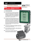
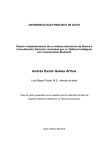
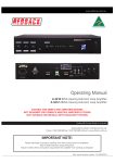
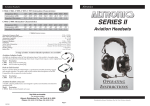
www.altronicinc.com
OPERATING MANUAL
WARNING:
WARNING:
FROM
THESE INSTRUCTIONS
LEAD TO OPDEVIATIONDEVIATION
FROM THESE
INSTRUCTIONS
MAY LEADMAY
TO IMPROPER
IMPROPER
OPERATION
THE ENGINE
COULD
ERATION OF
THE MACHINE
WHICHOFCOULD
CAUSEWHICH
PERSONAL
INJURY
CAUSEOR
PERSONAL
INJURYPERSONNEL.
TO OPERATORS OR OTHER
TO OPERATORS
OTHER NEARBY
NEARBY PERSONNEL.
AIR-FUEL CONTROLLER
EPC-110/120-1
EPC-110/120-2
FORM EPC-110/120 OM 10-07
1.0 SYSTEM DESCRIPTION
1.1 The Altronic EPC-110 and the EPC-120 are air/fuel ratio
controllers for use on carbureted gas engines. These controllers utilize microprocessor technology, allowing a high
level of sophistication in control strategy, ease of programming and diagnostic capability. The EPC-110 is intended
for stand-alone, off-engine post- or wall-mounting. The
EPC-120 is intended for off-engine, panel mounting. Both
controllers are identical in operation. The EPC-110/120 is
designed for use on engines operating at or near a stoichiometric air/fuel ratio (lambda .95 - 1.05) and is ideally
suited for application with 3-way catalytic converters.
1.2 The EPC-110/120-1 provides single channel operation for
applications with one carburetor. The EPC-110/120-2 provides
dual channel operation for applications with one or two carburetors. Inputs and outputs are used in duplicate for a V-engine with
two carburetors. An oxygen sensor is used in the exhaust stream to
sense O2 content; a thermocouple input signals when proper temperatures have been reached to allow for accurate sensor operation.
A fuel/control valve installed in the fuel line to the carburetor is precisely adjusted by a stepper-motor under microprocessor control to
maintain the correct O2 content in the exhaust. The desired air/fuel
ratio can be easily adjusted by changing the control target voltages
through the sealed membrane keypad or through the use of a PC.
1.3 The EPC-110/120 has an alphanumeric LCD display showing the
target voltage, sensor voltage, operating temperature, stepper
motor position and diagnostic information.
1.4 Power requirement is 24 (10–30) VDC, 1 amp. In remote
areas, power can be provided by the Altronic 24 VDC
Alternator Power Package. Refer to Altronic Form ALT.
1.5 The EPC-110/120 also incorporates thermocouple inputs and a dedicated output for implimentation of catalyst over-temperature protection.
www.altronicinc.com
1
EPC-110/120 AIR-FUEL CONTROLLER
2.0 SYSTEM COMPONENTS
2.1 One part from each group below is required for each installation:
PART NO.
DESCRIPTION
QUANTITY REQUIRED
EPC-110-1
EPC-110-2
Air/fuel controller, stand-alone
Air/fuel controller, stand-alone
1 per engine–single bank
1 per engine–dual bank
EPC-120-1
EPC-120-2
Air/fuel controller, panel mount
Air/fuel controller, panel mount
1 per engine–single bank
1 per engine–dual bank
690154-1
690154-2
690154-5
690220-1
690225-1
690230-1
Control Valve, standard 1.5” NPT 1 per carburetor
Control Valve, low HP 1.5” NPT
Control Valve, very low HP 1.5” NPT
Control Valve, butterfly 2.0” NPT
Control Valve, butterfly 2.5” NPT
Control Valve, butterfly 3.0” NPT
693005-1
693005-2
Cable, control valve, 25 ft.
1 per carburetor
Cable, control valve, 50 ft.
693006-1
693006-2
Cable, oxygen sensor, 25 ft.
1 per carburetor
Cable, oxygen sensor, 50 ft.
610621
Oxygen sensor
1 per carburetor
**
“K” Thermocouple Probe (ungrounded w/thermowell)
1 per carburetor, plus 2 for
Catalyst In/Out
**
“K” Thermocouple Ext. Wire
50 ft. per thermocouple
**
12-16 AWG Hook-up Wire
150 ft. per engine
** Not supplied in Altronic kits.
2.2 FIG. 14 lists the accessory kit contents.
2.3 REFER TO FIGS. 1 OR 2 for the general layout of components used in the
EPC-110/120 control systems.
3.0 MOUNTING THE EPC-110/120
3.1 The EPC-110 fiberglass enclosure is designed and intended for offengine, stand-alone post- or wall-mounting. REFER TO FIG. 3
3.2 The EPC-120 traditional painted steel enclosure is designed and intended for off-engine, panel mounting. REFER TO FIG. 4
3.3 Mounting location for EPC-110/120 should be chosen to minimize
exposure to vibration.
3.3 Operating temperature range is -40° to 158°F. / -40° to 70°C.
Humidity specification is 0-95%, non-condensing. Housed in a
2 FORM EPC-110/120 OM 10-07
NOTE: If possible, keep the
original shipping container.
If future transportation or
storage of the controller is
necessary, this container
will provide the optimum
protection.
EPC-110/120 AIR-FUEL CONTROLLER
NEMA 4X enclosure, the EPC-110 is rain and weather resistant;
however the mounting site should provide as much protection
from inclement weather as is practical. Avoid mounting the LCD
display and keypad in direct sunlight.
4.0 MOUNTING THE OXYGEN SENSORS
4.1 The sensor should be installed in the exhaust system between the
NOTE: A weldment boss may
be required for sensor installation in soft or thin wall
exhaust systems.
engine and the catalytic converter and/or muffler. The mounting
location should be as close to the exhaust manifold of the engine
as possible. The tip of the sensor should be exposed to the unobstructed flow of the exhaust gases from all cylinders to be controlled
by that sensor. On a V-engine using two control banks, each sensor
should be mounted such that it is exposed only to exhaust from the
appropriate bank of the engine. This requires that the sensors be
positioned at a point before the two banks join together. On engines
using only one control bank, exhaust flow from all cylinders must
be sensed. This means that the sensor should be mounted near, but
still before the exhaust stack. DO NOT locate the sensor in a coupling
or in a location where the exhaust gas flow is uneven due to obstructions or sharp bends. The sensor location chosen should allow easy
access since sensor replacement may be required as often as every
2000 hours in some applications. The location chosen should not
subject the exterior shell of the sensor to an ambient air temperature greater than 350°F.
4.2 Drill, tap and spot face a hole in the exhaust pipe at the selected location. A flat smooth sealing surface is required to assure accurate
readings since air or exhaust leaks will impact sensor operation.
SEE FIG. 5 FOR DETAILS
4.3 New sensors are packaged with an anti-seize compound already applied to the threads. There is no need to apply additional anti-seize
unless reinstalling a used sensor. If required, use high temperature
anti-seize very sparingly and apply only to the sensor threads. Sensors should be torqued to 28-34 lb.-ft.
www.altronicinc.com
3
EPC-110/120 AIR-FUEL CONTROLLER
5.0 MOUNTING THE K-TYPE THERMOCOUPLES
5.1 EXHAUST TEMPERATURE THERMOCOUPLES are used to monitor the tem-
perature of exhaust gases near the exhaust oxygen sensor and
should be mounted as close as possible to the appropriate O2 sensor. As with the O2 sensor, the location should be easily accessible,
and the tip of the probe, which should be enclosed by a thermowell,
should be surrounded by unobstructed exhaust flow.
5.3 CATALYST PROTECTION THERMOCOUPLES should be installed in the cata-
lyst housing. Provision for thermocouple installation is normally
provided for in the design and manufacture of the catalyst. Installation of the thermocouples on the inlet to the catalyst and the outlet of the catalyst provides three modes of protection: High Inlet
Temp Shutdown, High Outlet Temp Shutdown and High Catalyst
Temperature Rise Shutdown. Consult catalyst manufacturer’s recommendations for required overtemp protection.
5.3 ONLY UNGROUNDED THERMOCOUPLE PROBES can be used with the EPC-
110/120. Grounded type thermocouples will not function correctly.
Resistance from either lead of the thermocouple to the probe shell
should be 2 megohms or greater.
4 FORM EPC-110/120 OM 10-07
EPC-110/120 AIR-FUEL CONTROLLER
6.0 MOUNTING THE FUEL CONTROL VALVES
NOTE: For detailed instructions covering the gas control
valve, see form GCV1 OM
(690154 series) or GCV2 OM
(6902XX series).
6.1 In order to control the air/fuel ratio, an electronically controlled
valve is connected in series between each regulator and carburetor. These valves should be installed as close to the fuel inlet of the
carburetors as possible. The distance from the valve to the carburetor inlet should not exceed 12 pipe diameters in length. The valves
should be installed with the control cable connector facing upward
to avoid the collection of condensation in the stepper motor. Predrilled mounting holes are provided for user supplied brackets.
6.2 If possible connection piping should be of the same diameter as
currently in use. The threaded connection to the valve body may
require the use of thread adapters. If adapters are used, proper
plumbing procedures must be followed.
6.3 The control valves are connected to the EPC-110/120 using the 693005
cables. If it is desired to enclose the cables in conduit this can be accomplished by cutting the 693005 cable in half. The cables are color
coded and must be reconnected with each wire color matching. These
cables must not be run in the same conduit as the ignition primary or
other wires. A distance of 4 to 6 inches should be maintained between
EPC-110/120 wiring and other engine wiring. Note that the upper connector on the EPC-110/120 controls the stepper valve for single control
channel applications and the left bank valve on V-engines.
www.altronicinc.com
5
EPC-110/120 AIR-FUEL CONTROLLER
7.0 ELECTRICAL HOOK-UP
7.1 The power connections to the EPC-110/120 must be in accordance
with the National Electrical Code. The EPC-110/120 is suitable for
installation in Class I, Division 2 Group D locations.
7.2 Although the input power has internal protective fuses (3 amp), an
external fuse (5 amp min.) near the power source is recommended.
7.3 The EPC-110/120 can be powered in one of the following ways:
• 24 volt battery with trickle charger (1 amp min. output).
• DC power supply capable of furnishing 10-30 VDC, 2 amps.
• Altronic 24 VDC Alternator Power Package –see form ALT.
7.4 Power wiring and signal (transducers) wiring must be in separate
conduits and conduit entries into the EPC-110/120 to avoid undesired electrical interaction. Separate as follows (SEE FIG. 6):
Left Conduit Entry: Power Wiring and Earth Grounding
Center Conduit Entry: Signal Wiring: Oxygen Sensor wiring and Thermocouple inputs.
Right Conduit Entry: Alarm Outputs
7.5 Input power supply wires (16 AWG minimum) should enter the left
most conduit entry and connect to the 24 volt supply terminals of
terminal block TS2A. An earth ground wire (12 AWG minimum)
should enter this same location and connect to the Earth Ground
terminal. This connection is in addition to the power negative which
may also be grounded.
7.6 Oxygen Sensors are connected via shielded cable P/N 693006. These
should be run in conduit with, AND ONLY WITH, the EPC-110/120 thermocouple connections. These cables should enter the EPC-110/120
enclosure through the center conduit opening and connect to terminal block TB4. The red wire should be connected to the O2 sensor
(red) terminal, and the black wire to the O2 sensor (black) terminal.
The shield wire should be cut short and not connected. Care should
be taken to identify the left from right bank sensor wires. The cables
provided are terminated with weather tight connectors which mate
to the O2 sensors provided by Altronic. The shield wire (green wire
at connector end) must be connected to the exhaust piping near to
the sensor. This shield will assist in rejecting noise from other wiring which could affect the O2 sensor signal.
NOTE: Voltage and current
supplied must be sufficient
to operate all transducers
used in the installation. If
a heated Oxygen Sensor is
required, the heater current
must be added to the requirements shown.
REFER TO FIGS. 5 AND 6
6 FORM EPC-110/120 OM 10-07
NOTE: Engines using positive ground DC accessories
or starter motors will require
a separate dedicated ungrounded power supply for
the EPC-110.
EPC-110/120 AIR-FUEL CONTROLLER
7.7 The thermocouple (24 AWG min. type K extension) wires should
be run in a conduit with and only with the EPC-110/120 O2 sensor
wires. These thermocouple wires should enter the enclosure through
the center conduit opening and connect to terminal block TB4. The
yellow wire should be connected to the T/C (YELLOW) terminal and
the red wire to the T/C (RED) terminal. Again, care should be taken to
identify the four thermocouple wires (LEFT, RIGHT, CATIN, CATOUT).
Although the EPC-110/120 does not require a computer to be operated or installed, a serial port, located on the control board assembly, has been included which can be used to communicate with a
personal computer. Connections to the RS-485 port are made via
TS3, a 3-position plug located near the center of the circuit board.
A software terminal package which permits communication with
the EPC-110/120 is provided on a CD-ROM shipped with each unit.
This Modbus based PC program provides operational monitoring
and the capability to adjust default parameters and setpoints remotely. On screen directions and help are provided by the Altronic
terminal software. Modbus communication register lists may be
used to interface to PLC or SCADA systems.
SEE SECTION 20.0 FOR DETAILS
7.8 The CATALYST TEMP ALARM OUTPUT is configured as a normally closed
output signal. Any of the protection shut down (PSD) diagnostic
thresholds will cause this output to open. Connect this output to
the safety shutdown system in combination with a relay to result
in an engine shutdown for the purpose of catalyst protection. This
output is not latching and self-resetting upon the clearing of related protection conditions. (SOLID STATE SWITCH RATED 30
VOLTS/0.5 AMPS MAX)
Note: this output can be
restored to the closed position by pressing the ALARM
ACK key to acknowledge the
condition.
7.9 The ALARM OUTPUT is configured as a normally closed output signal.
Any diagnostic relating to measured temperatures, O2 sensor voltages, or rich or lean limit stepper positions will cause this output
to open for identification of possible improper airfuel control system operation. This output is not latching and is self-resetting upon
the clearing of all the alarm conditions. (SOLID STATE SWITCH
RATED 30 VOLTS/0.5 AMPS MAX)
7.10 Although the EPC-110/120 does not require a computer to be operated or installed, a serial port, located on the control board assembly, has been included which can be used for MODBUS RTU slave
communications. Connections using RS-485 (3 position plug TS3)
or RS-232 (DB9 connector) are supported (SEE FIGURE 7). The port
configuration is accomplished using the display and keypad as described in SECTION 12.18.
SEE SECTION 20.0 FOR MODBUS REGISTER DETAILS.
www.altronicinc.com
7
EPC-110/120 AIR-FUEL CONTROLLER
8.0 THEORY OF OPERATION
8.1 The primary task of the EPC-110/120 is to accurately control the
exhaust air fuel ratio (AFR) of an engine. Control should be maintained through reasonable load and fuel BTU variations.
8.2 Three-way catalysts are used to oxidize CO and HC and to reduce
NOx. These processes require high temperature and correct AFR
control. Catalysts perform best for all emissions when operated
near the stoichiometric AFR.
8.3 The stoichiometric AFR is the AFR at which exactly the required
amount of air (O2) is present to completely burn all of the fuel. Because no engine can perform perfect combustion, typical emission
by-products include O2, HC, NO and CO even though the engine
is running at stoichiometry. The stoichiometric AFR is determined
by the chemical composition of the fuel, thus they are different for
each fuel, or BTU rating.
(e.g. Methane => 16.09 : 1 and Gasoline => 14.70 : 1)
8.4 Because the fuel type is not always known, it is often easier to specify the AFR target in terms of Lambda. Lambda is an indicator of
AFR normalized to the appropriate Stoichiometric AFR.
(Lambda Actual AFR/Stoichiometric AFR)
Thus Lambda for stoichiometric combustion would be 1.0, no matter what the fuel.
Lambda > 1 = Lean, Lambda < 1 = Rich.
8.5 An O2 sensor (lambda sensor) is used to provide exhaust AFR feed-
back to the EPC-110/120. This type of sensor uses a zirconia element which, when combined with a catalyzing outer surface, creates an output voltage used to indicate lambda. Characteristics of
the sensor include: an output range of about 0.1 to 0.9 volts when
above 650°F, a very high output impedance when cool, a very high
sensitivity at stoichiometry and a very low sensitivity away from
stoichiometry. The output signal provides a very suitable means of
controlling just rich of Lambda 1.0 which is the AFR range required
to obtain best catalyst efficiencies for methane-based fuels.
FIG. 4 describes a typical sensor output voltage curve versus lambda.
8.6 Type K thermocouples are used to assure that exhaust tempera-
tures are high enough for correct operation of the sensor before
closed loop control is enabled. Additional thermocouples are used
to monitor catalyst temperatures: In, Out and Rise. Temperature
limit setpoints are provided to create a catalyst protection shutdown capability.
8 FORM EPC-110/120 OM 10-07
EPC-110/120 AIR-FUEL CONTROLLER
8.7 An electronic valve is used to create a variable restriction between
the fuel pressure regulator and the carburetor inlet. This restriction is used to adjust the effective inlet pressure seen by the carburetor and results in a mechanical adjustment of the air/fuel mixture
delivered by the carburetor. A stepper motor adjusts the restriction
by moving a plunger inside the valve. A stepper motor is a brushless
motor consisting of a permanent magnet armature and a four-coil
multi-pole stator. The armature is moved by sequentially pulsing
the four stator coils. Coupled to a worm screw, the rotating armature of the motor provides very accurate linear positioning capability. The motor used provides 1700 steps of travel at .0005 inch/step
for a total valve stroke of 0.85 inch.
8.8 The EPC-110/120 adjusts the stepper motor to maintain a specific
input voltage from the O2 sensor. When the sensor voltage is above
the O2 Target voltage, the system is richer than desired, and the
stepper position is increased to further restrict fuel flow to the carburetor. Conversely, when the sensor voltage is below the O2 Target
voltage, the system is leaner than desired, and the stepper position
is decreased to reduce the restriction of fuel flow.
8.9 Because the sensor voltage output is not linear with lambda, it
would not be practical to adjust the system faster when the error
from the set-point is greater. So in order to maximize the control
response, the motors are instead adjusted faster as the error persists longer. This method provides rapid response characteristics as
well as control stability. Control target voltages must be determined
with the use of an exhaust analyzer to locate the operating point
of lowest stack emissions. These target values are adjustable in the
EPC-110/120 through the keypad. The resulting system provides
accurate and stable control of air/fuel ratio which results in high
catalyst efficiencies and reduced stack emissions.
www.altronicinc.com
9
EPC-110/120 AIR-FUEL CONTROLLER
9.0 PRE-START INSTALLATION CHECKLIST
9.1 BEFORE APPLYING POWER TO THE EPC-110/120:
A. Measure the power supply voltage to assure voltage is within
limits (10-30 volts). Leave unit un-powered.
B. Inside the EPC-110/120, disengage terminal block TB4 and
measure resistance between the red and black O2 sensor wires.
Resistance should be higher than 2 megohms if sensors are
cool. This verifies that wires are not shorted in conduit.
C. Inside the EPC-110/120, disengage terminal block TB4 and
measure voltage between yellow and red thermocouple
wires. The voltage should be 0.80-1.50 mV for temperatures
60-100°F. This verifies that thermocouple wires are terminated. If engine had been running, measurements will be
higher, reflecting higher actual temperatures.
D. With the terminal block still disengaged, measure resistance between the red wire and the still connected earth
ground terminal. Resistance should be very high or open
circuit. Repeat measurement between yellow wire and earth
ground. This verifies that thermocouples are ungrounded
and that wires are not shorted in conduit.
9.2 WITH THE EPC-110/120 POWERED UP AND THE ENGINE NOT RUNNING:
A. Display should follow the power-up sequence DESCRIBED IN
SECT. 11.2.
B. Display of O2 sensor voltages should go to 0.5 volts. This
may require a few minutes. SECTION 14.0 explains how to
view data screens.
C. Data display screen for exhaust temperatures should indicate ambient temperatures.
D. Disengage terminal block TB4 and measure voltage between
black O2 sensor wire and still connected earth ground terminal. The voltage should be 0 volts ± 50 mV. This is to test
for potential ground loop problems.
E. Control valve operation should be verified during a start
position command. This can easily be done if the valves are
not yet fully installed in the fuel line. Press ALARM ACK if
the alarm LED is on. Then press F1 followed by START POS.
During the start position activity, the left valve plunger
should be fully retracted then positioned near the middle of
its travel, followed by the right valve. No movement, erratic
movement, or movement in the wrong direction will result
from incorrect wiring of the stepper cables.
10 FORM EPC-110/120 OM 10-07
NOTE: If engine was running
recently, temperature will be
higher.
NOTE: Ground loops could
be more significant when
the engine is running. The
addition of other electrical
devices may affect EPC operation with regard to signal
offsets.
EPC-110/120 AIR-FUEL CONTROLLER
F. RETURN THE SET-UP VALUES TO THE FACTORY DEFAULTS:
This can be done by slowly pressing the following keys in order F1, F3, F2, F4. Then, once the screen indicates that you are
in the set-up mode, press F2 followed by F2 again to restore
default setup values. Then press F4 to exit the setup mode.
The default values are set as follows:
Left O2 Target = 0.80 volts
Left Default Position = 1000 steps
NOTE: Settings should be
established based on catalyst manufacturer’s recommendation.
Gain Value = 0.50
Right O2 Target = 0.80 volts
Right Default Position = 1000 steps
G. CONFIGURE CATALYST PROTECTION THRESHOLDS:
This can be done by slowly pressing the following keys in
order F1, F3, F2, F4, Then, F1 to view each successive set-up
parameter:
Exh Temp Hi = 1000°F
Exh Diff Hi = 200°F
Cat In Hi = 1000°F
Cat Out Hi = 1100°F
Cat Rise Hi = 100°F
9.3 When all of these checks have been made successfully, move on to
the Start-Up Procedure.
www.altronicinc.com
11
EPC-110/120 AIR-FUEL CONTROLLER
10.0 START-UP PROCEDURE
10.1 BEFORE STARTING ENGINE:
A. Check for fuel leaks where the fuel line was modified.
B. Verify that a catalyst over-temp thermocouples and thresholds are in place and functional according to catalyst provider requirements and recommendations.
C. Press F1, then press START POS on the EPC-110/120 keypad to
reset stepper position and enable the warm-up delay.
D. Be sure that the power screw adjustments on carburetors are full
open or full rich. If these adjustments are not fully open, then the
control range of the stepper control valve will be limited.
E. If the alarm outputs of the EPC-110/120 are being used,
temporarily disconnect or override these signals so that an
alarm indication will not shut down the engine during setup.
F. Verify that the catalyst protection output is wired and functional to cause a shutdown in an overtemp condition.
G. Place EPC-110/120 controller in MANUAL mode by pressing
LEFT MANUAL, then RIGHT MANUAL keys.
H. Start and warm-up engine.
10.2 WITH THE ENGINE RUNNING:
A. Load engine to desired operating point.
B. Verify that the exhaust temperature data screen is displaying reasonable values, and that the temperatures exceed
650°F. REFER TO SECTION 14.0 FOR DISPLAY KEY OPERATION
C. Enable automatic control by pressing the AUTO OPER key. The
unit should begin adjusting the stepper valves trying to control the engines air/fuel ratio. Use any diagnostic warnings
which may occur to trouble-shoot the system. Rich or lean
limit errors are a good indication that the pressure regulators need some adjustment.
D. Once the unit has gained control of the engine (O2 sensor
voltage very near the target voltage), adjust the fuel pressure regulators until the EPC-110/120 is controlling with
the stepper valve positions near 1000 steps. This is approximately the middle of the valve’s control range.
12 FORM EPC-110/120 OM 10-07
EPC-110/120 AIR-FUEL CONTROLLER
10.3 FINE TUNE THE CONTROL SETPOINTS:
A. Using an exhaust analyzer, determine the set-point voltage
which results in the best emission performance. This can
be done by incrementally adjusting the O2 Target voltage in
the Set-Up Mode. Reference section 12.0 for an explanation
of the setup mode. Alternatively, manual mode can be used
to adjust the control valves to the positions which give the
best emissions performance. REFERENCE SECTION 15.0 for an
explanation of manual mode operation. Then the O2 Target
voltages should be adjusted to match the actual sensor voltages using the SET-UP mode.
B. The control gain rate and default stepper positions can also
be adjusted now; however, the default values represent the
best typical values for these parameters.
10.4 ONCE THE SYSTEM IS CONTROLLING AT THE BEST EMISSIONS POINT, THE ALARM
OUTPUT CAN BE RE-ENABLED.
10.5 AT THIS POINT, THE EPC-110/120 SET-UP IS COMPLETE; THE UNIT SHOULD BE CONTROLLING THE ENGINE.
www.altronicinc.com
13
EPC-110/120 AIR-FUEL CONTROLLER
11.0 GENERAL: KEYPAD AND DISPLAY OPERATION
11.1 The EPC-110/120 includes a front-mounted keypad and an LCD dis-
play which permits the monitoring and adjustment of various parameters and actions. Two LED indicators are also included. The
power LED (GREEN) is illuminated any time there is power to the
unit. The alarm LED (YELLOW) will come on momentarily on power
up then go out as soon as the unit is running. The alarm LED is used
to indicate when a diagnostic test is violated. REFERENCE SECTION 16.0
for more detail regarding diagnostics and the alarm indicator.
11.2 The keypad and display function together as the user interface. Only
one key on the pad should be pressed at one time. Some commands
require a key sequence (a series of key presses, one followed by the
next). Whenever possible, special messages indicate what is happening or why a command is not accepted.
11.3 With the engine not running (cool exhaust), when power is first applied
to the EPC-110/120, the display will show an Altronic product description message.
Altronic Inc.
EPC110/120 Stoic
11.4 After a few seconds the display will indicate that the controller is in
warm-up mode. This display indicates that the thermocouples are
still reading temperatures too cool for the O2 sensors to function
correctly. The number at the end of the message indicates the current stepper valve position in steps. If the engine is not started this
condition will persist for 10 minutes.
11.5 After 10 minutes with a cool exhaust, the display will now begin ro-
tating the diagnostic messages for low exhaust temperature. All diagnostic messages include the ! character for recognition. Diagnostics
exist for several functions and are EXPLAINED IN DETAIL IN SECTION 16.
When any diagnostic condition is present, the status containing ! will
appear, then all of the appropriate descriptions will follow in rotation.
The number in the warning message represents the present stepper
valve position.
11.6Press ALARM ACK and the alarm LED which was turned on by the
above warning will begin to flash. The low temperature alarm has
now been acknowledged and the EPC-110/120 will accept other keypad commands. Any time the alarm LED is on steady, no keypad
commands will be accepted until the ALARM ACK key is pressed. The
display will indicate that the unit is responding to this command
with message WORKING.
14 FORM EPC-110/120 OM 10-07
L AutoWarmUp1000
R AutoWarmUp1000
L!Auto!.802v1000
R!Auto!.802v1000
AND
L! EXH TEMP LO !
R! EXH TEMP LO !
EPC-110/120 AIR-FUEL CONTROLLER
12.0 SETUP MODE: KEYPAD AND DISPLAY OPERATION
NOTE: all screens in setup
mode include the $ character.
12.1 Once the alarm LED is no longer on steadily, press F1 followed by F3
followed by F2 followed by F4. This is the setup mode entry key sequence. The display will indicate that the setup mode is now active.
$$$ SETUP $$$
F1=Next F4=EXIT
12.2Press F2 then press F2 again to restore factory default parameters.
This special command can be used only from this screen when the
user wants to restore factory default values. A message will indicate
that the default values have been restored, then will return to the
main setup message. NOTE DEFAULT VALUES LISTED IN SECTION 9.2
F2
RESTORING
DEFAULT SETUP
THEN
F2
$$$ SETUP $$$
F1=Next F4=EXIT
12.3Press F1 to increment to the control gain setup screen. The factory
default value for this parameter is 0.50 as shown on the display.
This parameter determines the stepper valve adjustment rate when
in automatic mode. The higher the value the faster the controller
will move the stepper in response to the O2 sensor.
F1
NOTE: Multiple presses of
the key are required to continue incrementing the value.
If the key is held, the value
will be adjusted at a progressively faster rate.
$ F2=Up F3=Dn $
GAIN VALUE=0.60
12.4Press F2 to increase the value for the gain parameter. The display will
indicate that the value has been changed. At this point the value is
updated and will be used until the value is changed again.
F2
$ F2=Up F3=Dn $
GAIN VALUE=0.60
www.altronicinc.com
15
EPC-110/120 AIR-FUEL CONTROLLER
12.5Press F3 to decrease the value. Now the value is decreased to the
default value again. The range for the gain value is limited to (0.1 to
2.0). The value cannot be moved beyond its limits.
F3
$ F2=Up F3=Dn $
GAIN VALUE=0.50
12.6Press F1 to increment to the left O2 Target setup screen. The factory
default value for this parameter is 0.80 volts as shown on the display. Like the gain value, the target can be increased and decreased
with the F2 and F3 keys. The typical range is near 0.8 volts. The allowable range is 0.01 to 1.05; however most sensor’s output range is
limited to 0.1 to 0.9 volts.
F1
$ F2=Up F3=Dn $
LO2SetPnt=0.800v
12.7Press F1 to move to the right O2 Target setup screen. This screen
functions just like the one described in section 12.6 for the left bank.
In a single bank application, this set-up screen would be skipped.
F1
$ F2=Up F3=Dn $
RO2SetPnt=0.800v
12.8Press F1 to rotate to the left default stepper position screen. The
default position is used when any of the O2 sensor or thermocouple
diagnostics are active. The number on the right is the current default position. Because the temperature diagnostic is still active, the
actual stepper position on the left is also 1000.
F1
$F2=chng L.dflt$
1000 ---> 1000
16 FORM EPC-110/120 OM 10-07
EPC-110/120 AIR-FUEL CONTROLLER
12.9Press F2 to update the default position (on right) with the value of
the current position (on left). Since both values are the same no
change was actually made in this example. By using the manual
mode which is DESCRIBED IN SECTION 15.0, the actual position can be
adjusted to the desired position before entering the setup mode.
F2
UPDATING LEFT
DEFAULT POSITION
THEN
$F2=chng L.dflt$
1000 ---> 1000
12.10Press F1 to move to the right default stepper position screen. This
screen functions just like the one described in section 12.7 for the
left bank. In a single bank application, this set-up screen would be
skipped.
F1
$F2=chng R.dflt$
1000 ---> 1000
12.11Press F1 to rotate to the first temperature protection setup value.
The EXHAUST TEMPERATURE HI setpoint represents the maximum permitted engine exhaust temperature as sensed by the left and right
(dual bank) thermocouples mounted near the O2 sensors. High temperatures at these locations may indicate engine overload or engine
misfire. The CATALYST TEMP ALARM output as well as the ALARM output
switch will open if this threshold is exceeded to cause a protection
shutdown. The same value is used to test both left and right bank
temperatures.
F1
$ F2=Up F3=Dn $
ExhTempHi=1000°F
www.altronicinc.com
17
EPC-110/120 AIR-FUEL CONTROLLER
12.12Press F1 to rotate to L VS R EXHAUST TEMPERATURE DIFFERENCE HI setting.
For dual bank applications, the absolute difference between the left
and right bank thermocouples will be compared to this threshold.
If the temperature difference exceeds the setpoint, then the CATALYST TEMP ALARM output as well as the ALARM output switch will open
to cause a protection shutdown. A condition of misfire or improper
bank to bank engine balance are potential conditions identified by
this test.
F1
$ F2=Up F3=Dn $
ExhDiffHi= 200°F
12.13Press F1 to display the CATALYST-IN HI temperature setpoint threshold.
If the inlet temperature to the Catalyst should exceed this setting,
then the CATALYST TEMP ALARM output as well as the ALARM output
switch will open to cause a protection shutdown. Conditions of misfire or overload or improper engine operation may be identified by
this test. Extreme temperature at the inlet to the catalyst will lead
to premature failure of the catalyst element and its support structure. Consult the catalyst manufacturer for the recommended inlet
temperature shutdown limits.
F1
$ F2=Up F3=Dn $
CatInHi =1000°F
12.14Press F1 to display the CATALYST-OUT HI temperature setpoint threshold.
If the outlet temperature of the Catalyst should exceed this setting, then
the CATALYST TEMP ALARM output as well as the ALARM output switch will
open to cause a protection shutdown. Conditions of misfire or overload
or improper engine operation may be identified by this test. Extreme
temperature at the outlet of the catalyst indicates that the catalyst is
being damaged by the operation conditions of the engine. Provision
may be provided in the catalyst to mount a temperature probe at the
catalyst element. This location may serve as an alternative to catalyst
outlet temperature. Consult the catalyst manufacturer for the recommended outlet-temperature shutdown limits.
F1
$ F2=Up F3=Dn $
CatOutHi =1100°F
18 FORM EPC-110/120 OM 10-07
EPC-110/120 AIR-FUEL CONTROLLER
12.15Press F1 to display the CATALYST TEMPERATURE RISE HI setpoint thresh-
old. The temperature difference Outlet – Inlet is compared to this
setpoint to identify excessive temperature rise across the catalyst.
This condition of temperature rise is an indication that the catalyst
is reacting unburned air and fuel that may result from a misfire
or condition. If the temperature rise across the Catalyst should exceed this setting, then the CATALYST TEMP ALARM output as well as the
ALARM output switch will open to cause a protection shutdown. Consult the catalyst manufacturer for the recommended temperature
rise shutdown limits.
F1
$ F2=Up F3=Dn $
CatRiseHi= 100°F
12.16Press F1 to display the NUMBER OF BANKS setting screen. Should a dual
bank EPC-110/120 be applied to a single bank application, this screen
provides the opportunity to select the single bank operation mode.
This setup value is not presented on the single bank EPC-110/120
model.
F1
$ F2=Up F3=Dn $
Number Banks = 2
12.17Press F1 to display the MODBUS NODE ID setup screen. Valid node ID’s
are 1 to 250 permitting the communication system to incorporate
multidrop communications to various ModBus slave devices.
F1
$ F2=Up
ModBus
F3=Dn $
ID=100
12.18Press F1 to display the MODBUS PORT setup screen. Various baud rates
and parity modes are supported by the EPC-110/120. The selections
include baud rates of (300, 600, 1200, 4800, 9600, 19200, 38400,
57600). The selection of parity includes (Even, Odd and None). The
selection of port types includes (RS485 and RS232, both support
half-duplex ModBus RTU).
F1
$ F2=Up F3=Dn $
485ModBus9600n81
12.19Press F1 to rotate back to the main screen.
F1
$$$ SETUP $$$
F1=Next F4=EXIT
www.altronicinc.com
19
EPC-110/120 AIR-FUEL CONTROLLER
12.20Press F4 to exit the setup mode. F4 can be used from any setup
screen. Remember all setup screens have the $ character on them
somewhere. This returns the display to the warning message which
was caused by low exhaust temperatures.
F4
L !WARNING! 1000
R !WARNING! 1000
AND
L EXH TEMP LO !
R EXH TEMP LO !
Note: Loading default settings as shown in section
12.2 does not affect settings relating to the Catalyst Temp Alarm Output or
ModBus configuration.
20 FORM EPC-110/120 OM 10-07
EPC-110/120 AIR-FUEL CONTROLLER
13.0 ENGINE STARTUP: KEYPAD AND DISPLAY OPERATION
13.1Press ALARM ACK to acknowledge alarms if alarm LED is ON.
13.2Press F1 then press START POS to send the steppers to start posi-
tion (stepper default position) and disable the alarm warnings for
10 minutes. The controller will return each stepper to its start position and then display the warm-up screen. This procedure should
ALWAYS be used when starting the engine.
F1
Moving L Stepper
to Zero Pos.
Moving L Stepper
to START Pos.
Moving R Stepper
to Zero Pos.
Moving R Stepper
to START Pos.
L AutoWarmUp1000
R AutoWarmUp1000
13.3 Now the engine should be started, warmed up and loaded. Temperature requirements would be met before the 10 minute delay expires and the controller would go into automatic control. Both the
current left O2 sensor voltage, and the current left stepper valve
position are provided on the automatic display screen.
L AUTO .812v1010
R AUTO .796v 982
www.altronicinc.com
21
EPC-110/120 AIR-FUEL CONTROLLER
14.0 DATA VIEWING: KEYPAD AND DISPLAY OPERATION
14.1Press DSPL SEL to display the first data view screen. The first data
screen displays the current O2 sensor voltages.
DUAL BANK
DSPL
SEL
L O2Sensor=.812v
R O2Sensor=.796v
SINGLE BANK
AUTO .625v 985
02Sensor=.625v
14.2Press DSPL SEL again to display current O2 target voltages.
DUAL BANK
DSPL
SEL
L O2Target=.800v
R O2Target=.800v
SINGLE BANK
AUTO .625v 985
02Target=.800v
14.3Press DSPL SEL again to display the exhaust temperature readings
from the thermocouples near the O2 sensors.
DUAL BANK
DSPL
SEL
L EXH TMP=1024°F
R EXH TMP=1049°F
SINGLE BANK
AUTO .625v 985
EXH TMP=1049°F
22 FORM EPC-110/120 OM 10-07
EPC-110/120 AIR-FUEL CONTROLLER
14.4Press DSPL SEL again to display the Catalyst temperatures.
DUAL OR SINGLE BANK
DSPL
SEL
Cat Rise=+ 24°F
In=1098 Out=1125
14.5Press DSPL SEL again to loop back to the automatic screen.
DUAL BANK
DSPL
SEL
L AUTO .811v1010
R AUTO .796v 982
SINGLE BANK
DSPL
SEL
AUTO .811v1010
www.altronicinc.com
23
EPC-110/120 AIR-FUEL CONTROLLER
15.0 MANUAL MODE: KEYPAD AND DISPLAY OPERATION
15.1Press LEFT MAN to enter the manual mode for the left bank. The dis-
play will indicate WORKING and then return with the left bank in
manual mode. This mode can be used to help setup the controller, and to diagnose problems. Because no diagnostic alarms are
present, it was not necessary to acknowledge alarms. Also, once in
manual mode, diagnostic alarms for that bank are disabled. The
alarm LED will flash while in manual mode to serve as a reminder
that the EPC-110/120 is not in automatic control.
LEFT
MAN
L MAN! .811v1010
R Auto .796v 982
15.2Press RIGHT MAN to enter the right bank manual mode.
RIGHT
MAN
L MAN! .811v1010
R MAN! .796v 982
15.3Press LEFT LEAN to increase the stepper position by 25 steps. A descriptive message will be displayed and then the modified position
will be returned. Increasing the position causes the valve to close
and the mixture to change in the lean direction.
LEFT
LEAN
MOVING
STEPPER
THEN
L MAN! .811v1035
R MAN! .796v 982
15.4Press LEFT FAST, then press LEFT LEAN to increase the stepper position
by 100 steps.
LEFT
FAST
MOVING
STEPPER
THEN
LEFT
LEAN
L MAN! .811v1135
R MAN! .796v 982
24 FORM EPC-110/120 OM 10-07
NOTE: Both the ALARM
LED and the ALARM output
return to the normal condition when the system fault is
corrected.
EPC-110/120 AIR-FUEL CONTROLLER
15.5Press LEFT RICH to decrease the stepper position by 25 steps. Decreasing the position causes the valve to open and the mixture to change
in the rich direction. These same commands are used to operate the
right bank using the RIGHT LEAN, RIGHT RICH and RIGHT FAST keys.
NOTE: When F1 then START
are pressed before starting
the engine, the exhaust temperature diagnostic will be
delayed 10 minutes displaying the warm-up screen.
LEFT
RICH
MOVING
STEPPER
THEN
LEFT
MAN
L MAN! .811v1110
R MAN! .796v 982
15.6Press AUTO OPER to return to automatic mode. Any time this key is
pressed, automatic mode will be enabled for both banks.
AUTO
OPER
L AUTO .811v1110
R AUTO .796v 982
www.altronicinc.com
25
EPC-110/120 AIR-FUEL CONTROLLER
16.0 DIAGNOSTIC DISPLAYS AND OPERATION
16.1 ALARM LED AND ALARM OUTPUT
The ALARM LED and ALARM output operate in conjunction with the
diagnostic features of the EPC-110/120. The three operation modes
of these alarm features are described below:
A. Alarm LED OFF
Indicates that the unit is operating correctly in automatic
mode, or in warm-up mode waiting for the exhaust temperatures to increase.
B. Alarm LED ON Steady
Indicates that the unit is attempting automatic control; however one of the diagnostic criteria has not been satisfied. The
alarm indicator will stay on solid until the alarm acknowledge
key is pressed at which time the LED will flash. A solid on yellow LED also indicates that the alarm output terminal is in its
alarm state.
C. Alarm LED Flashing
Indicates one of two things; either an acknowledged alarm
condition still exists, or the unit is in manual operation mode.
The flashing LED should simply signify to the operator that
the unit is not in normal automatic control. The alarm output
terminal is in its normal state if the LED is flashing.
16.2 ALARM OUTPUT
The ALARM output is configured as a NORMALLY CLOSED output signal.
Any system fault will open the alarm circuit including loss of power, diagnostic warnings, etc. As described above, the alarm output
would be in its fault condition (open) any time that the alarm indicator on the front panel is ON solid.
16.3 SYSTEM DIAGNOSTICS
The system diagnostics included in the EPC-110/120 are designed
to identify conditions which are not considered normal operation.
These diagnostic tests are performed continuously while the controller is in automatic mode. Each of the diagnostics will display a
descriptive message, turn on the ALARM LED (YELLOW) and place the
alarm output in the fault condition (OPEN).
16.4 DIAGNOSTIC WARNING MESSAGES
Active diagnostic warning messages include the ! character and are
displayed in rotation, each message being displayed for about 1 second. The home screen uses the ! character to indicate the status and
that other diagnostics will follow in rotation.
L!Auto!.765v1000
R AUTO .801v 982
26 FORM EPC-110/120 OM 10-07
EPC-110/120 AIR-FUEL CONTROLLER
16.5 EXHAUST TEMPERATURE
The Exhaust Temperature diagnostic monitors the exhaust temperatures near the O2 sensors as measured with the thermocouples.
If the temperature is below 650°F or above 1400°F, then the EPC110/120 displays the appropriate low or high message and activates
the ALARM LED and ALARM output. Automatic control is also disabled and the stepper valves are positioned at the default stepper
position. Thermocouple probe or thermocouple connection failures
will also activate this diagnostic.
L EXH TEMP LO !
R Auto .800v 982
OR
L EXH TEMP HI !
R Auto .800v 982
16.6 SENSOR NOT READY
The Sensor Not Ready diagnostic is designed to identify problems
with the O2 sensor. The controller has a very high impedance pull up
resistor to 0.5 volts in parallel with each exhaust sensor input. When
the sensor is too cool or disconnected this will force the input to read
0.5 volts. If the controller sees that the sensor output is 0.5 volts for
10 or more seconds the EPC-110/120 will display the sensor not ready
message and activate the ALARM LED and ALARM output. Automatic
control is also disabled and the stepper valves are moved to the default stepper position. The sensor ready test is only performed if the
exhaust temperature requirements of 16.5 are satisfied. Failure of
this test indicates a cold, disconnected or failed sensor.
L O2 NOT READY !
R Auto .800v 982
www.altronicinc.com
27
EPC-110/120 AIR-FUEL CONTROLLER
16.7 SENSOR INPUT VOLTAGE
The Sensor Input Voltage diagnostic is also designed to identify
problems with the O2 sensor. Normal input voltages should be between 0.1 and 0.9 volts. If the sensor input voltage is less than 0.1
volts or more than 1.1 volts, the EPC-110/120 will display the appropriate low or high message and activate the ALARM LED and ALARM
output. Automatic control is also disabled, and the stepper valves
are moved to the default stepper position. Failure of this diagnostic
test indicates shorted wiring or a failed sensor.
L O2 SIGNAL LO!
R Auto .800v 982
OR
L O2 SIGNAL HI!
R Auto .800v 982
16.8 LEAN AND RICH LIMIT
The Lean and Rich Limit diagnostic monitors the stepper positions.
If the position of a stepper valve is at the minimum (0) or maximum
(1700) travel limit, the EPC-110/120 displays the appropriate message and activates the ALARM LED and ALARM output. The rich limit
warning indicates that the engine is too lean and the controller cannot open the valve any further to enrich the mixture. The lean limit
warning indicates that the engine is too rich and the controller cannot close the valve any further.
L RICH LIMIT !
R Auto .800v 982
OR
L LEAN LIMIT !
R Auto .800v 982
28 FORM EPC-110/120 OM 10-07
EPC-110/120 AIR-FUEL CONTROLLER
16.9 ENGINE OUT EXHAUST OVER-TEMPERATURE
When the left or right bank exhaust temperature exceeds the setup
threshold, the alarm output will open, the alarm LED will turn on,
the Catalyst Protection Alarm output (PSD) will open, and the messages below may be displayed.
DUAL BANK
!L ExhTempHiPSD!
R AUTO!WARN! 875
OR
L AUTO!WARN! 905
!R ExhTempHiPSD!
SINGLE BANK
AUTO!WARN! 905
!L ExhTempHiPSD!
16.10 ENGINE OUT EXHAUST DIFFERENTIAL
On a dual bank application, when the engine exhaust temperature
differential between the banks exceeds the setup threshold, the
alarm output will open, the alarm LED will turn on, the Catalyst
Protection Alarm output (PSD) will open and the message below is
displayed.
1LvsR Delta PSD!
!LvsR Delta PSD!
16.11 CATALYST INLET OVERTEMP OVER-TEMPERATURE
When the inlet temperature of the catalyst exceeds the setup threshold, the alarm output will open, the alarm LED will turn on, the
Catalyst Protection Alarm output (PSD) will open and the message
below is displayed.
L AUTO!WARN! 905
!CatInTempHiPSD!
www.altronicinc.com
29
EPC-110/120 AIR-FUEL CONTROLLER
16.12 CATALYST OUTLET OVER-TEMPERATURE
When the outlet temperature of the catalyst exceeds the setup
threshold, the alarm output will open, the alarm LED will turn on,
the Catalyst Protection Alarm output (PSD) will open and the message below is displayed.
L Auto!WARN!1000
!CatOutTmpHiPSD!
16.13 CATALYST TEMPERATURE RISE
When the temperature from the inlet to the outlet of the catalyst
exceeds the setup threshold, the alarm output will open, the alarm
LED will turn on, the Catalyst Protection Alarm output (PSD) will
open and the message below is displayed.
L Auto!WARN!1000
!CatTmpRise PSD!
30 FORM EPC-110/120 OM 10-07
EPC-110/120 AIR-FUEL CONTROLLER
17.0 AUTOLOG FEATURE
17.1 Press “F3” to display the first out Autolog screen which provides the
first most recent detected cause for leaving normal automatic operation. The cause is logged to a modbus register and also presented as
below on the screen using a text string. The example below indicates
that a difference in the left to right bank temperatures exceeded the
setpoint which resulted in a catalyst protection alarm which triggered the snapshot of auto log values. The auto log values are updated on every transition out of fully automatic control without alarms.
The table of auto log causes is shown below.
AutoLOG Code 67
!LvsR Delta PSD!
L! EXH TEMP LO !
R! EXH TEMP LO !
L! EXH TEMP HI !
R! EXH TEMP HI !
L! O2 SIGNAL LO!
R! O2 SIGNAL LO!
L! O2 SIGNAL HI!
R! O2 SIGNAL HI!
L! O2 NOT READY!
R! O2 NOT READY!
L! LEAN LIMIT !
R! LEAN LIMIT !
L! RICH LIMIT !
R! RICH LIMIT !
!L EXHTEMPHIPSD!
!R EXHTEMPHIPSD!
!LVSR DELTA PSD!
!CATINTEMPHIPSD!
!CATOUTTMPHIPSD!
!CATTMPRISE PSD!
!L USER MANUAL !
!R USER MANUAL !
www.altronicinc.com
31
EPC-110/120 AIR-FUEL CONTROLLER
17.2 The following screens are viewed in rotation, displaying the next
screen on each press of F3.
Identifies the left and right bank temperatures at auto log event.
AutoLOG Steppers
L 1191 R 990
Identifies stepper positions at auto log event trigger
AutoLOG EXH O2V
L 804v R .799v
Identifies O2 voltage measurements at auto log event trigger
AutoLOG CATtemps
In 985° Out1057°
Identifies catalyst temperatures at auto log event trigger
AutoLOG EXHtemps
L 817° R 1021°
AutoLOG Supply V
5.04vdd
2402v
Identifies internal and supply voltage at auto log event trigger
32 FORM EPC-110/120 OM 10-07
EPC-110/120 AIR-FUEL CONTROLLER
18.0 ADDITIONAL DISPLAY SCREENS
18.1 Three additional screens exist which can be helpful in obtaining information about the version and supply voltage and temperature of
the EPC-110/120. They can be viewed as follows.
Press F1 then DISP-SEL, to view the version number of EPC-110/120
firmware.
LOGIC
VER 1.1
DISPLAY VER 1.1
Press F2 then DISP-SEL, to view the version date of EPC-110/120
firmware.
LOGIC
09/19/07
DISPLAY 09/19/07
Press F1 then F2 then DISP-SEL to view the supply voltage and temperature.
Supply 24.3volts
Vdd=5.0 23.3°C
www.altronicinc.com
33
EPC-110/120 AIR-FUEL CONTROLLER
19.0 TROUBLE-SHOOTING THE EPC-110/120 SYSTEM
19.1 GREEN LED AND LCD DISPLAY ARE BLANK; POWER IS INTERRUPTED.
A. Check power supply voltage at EPC terminal block TS2A (1830 volts), while still connected.
B. Power down unit, then remove and check resistance of onboard fuses (F1) (< 2 ohms).
SEE FIG. 9
C. Verify tight cable connections between control and display
boards.
19.2 DISPLAY READS (EPC Bottom Board !NOT Running!); CONTROL BOARD IS NOT
RUNNING.
A. Power-down unit for 1 minute. Re-power, check display and
status of LED1C on logic board.
B. LED LIT AND NOT BLINKING INDICATES:
Firmware mismatch of versions
OR
Cable between logic and display loose or broken
OR
Display board damaged
OR
Logic board damaged
C. BLINKING LED INDICATES:
Logic board not running properly.
Verify IC in blue socket installed properly.
Replace logic board assembly.
D. LED NOT LIT INDICATES:
Replace logic board assembly
SEE FIG. 10 OR 12
19.3 DISPLAY TOP ROW IS DARK, BOTTOM ROW IS LIGHT; DISPLAY BOARD IS NOT RUNNING.
A. Power-down unit for 1 minute. Then re-power and check display.
B. On back of display board, examine both blue socketed IC’s for
tight engagement.
C. Check cable connection between control and display boards.
D. Replace display board assembly. SEE FIG. 10 OR 12
19.4 DISPLAY IS BLANK, BUT GREEN LED IS ON. CONTRAST ADJUSTMENT REQUIRED.
A. On back of display board adjust contrast potentiometer.
Clockwise = Lighter; Counterclockwise = Darker.
SEE FIG. 10/11 OR 12/13 FOR LOCATION.
B. Replace display board assembly. SEE FIG. 10 OR 12
34 FORM EPC-110/120 OM 10-07
EPC-110/120 AIR-FUEL CONTROLLER
19.5 KEY PAD ENTRIES CAUSE NO DISPLAY RESPONSE.
A. At bottom of display board, verify connection of keypad ribbon connector.
B. Replace enclosure and keypad assembly. SEE FIG. 10 OR 12
19.6 ALARM LED IS ON SOLID.
A. Read the warning message on the display, and reference the
diagnostic section for an explanation of the warning.
B.Press ALARM ACK to permit normal keypad operation and to
disable the alarm output terminal.
19.7 EPC-110/120 WILL NOT MOVE STEPPER VALVES DURING F1 THEN START
POS. COMMAND.
A. Check stepper cable connections at EPC-110/120 and at stepper
valve.
B. Inside EPC-110/120 verify that red LED on control board is
ON. If LED is off, or flashing check the fuses on the control
board.
C. Examine blue socketed I.C. for tight engagement.
D. Test EPC-110/120 with a spare stepper valve assembly.
E. Test EPC-110/120 and stepper valve assembly, with a spare
stepper cable.
F. Replace entire control board assembly. SEE FIG. 10 OR 12
19.8
HIGH OR LOW EXHAUST TEMP WARNINGS PERSIST.
A. Observe thermocouple readings for reasonable values using
display select screens in SECTION 14.
B. Compare observed readings to, and verify feasibility of catalyst protection setpoints as described in SECTION 9.2 (G).
C. If engine is not running, start and warm up engine.
D. Test the disconnected thermocouple reading at EPC-110/120
with an alternate thermocouple reading device.
E. Replace thermocouple or correct wiring if temperatures are
incorrect. The life of thermocouple probes is highly dependent
on the use of a thermowell and on corrosives in exhaust.
F. If low temperature is a problem during first installation, an
alternate sensor and probe location may be required. Please
contact the factory before pursuing any other action to raise
sensor temps.
G. Replace entire control board assembly. SEE FIG. 10 OR 12
www.altronicinc.com
35
EPC-110/120 AIR-FUEL CONTROLLER
19.9RICH OR LEAN LIMIT WARNINGS PERSIST.
A. A misfiring engine can cause the system to shift in the rich
direction. Check the engine for misfiring cylinders using a
timing light or exhaust pyrometer.
B. Use an exhaust analyzer and the EPC-110/120 manual mode
to adjust the %O2 before the converter to around 1.0%. If the
%O2 cannot be manipulated in the manual mode, then test to
make sure the stepper valve is functioning as was done during
installation.
C. If manual mode moves the %O2 but cannot attain 1.0%, then
the fuel system may need to be readjusted. First verify that
the load screw adjustments on the carburetors are full rich
or full open. If they are not full open, the control range of the
stepper valves will be limited. Second, adjust the fuel pressure regulators so that when in automatic mode, the stepper
valves are controlling near 1000 steps.
D. If the fuel system appears to be adjusting correctly, use an exhaust analyzer and the EPC-110/120 manual mode to sweep
the %O2 from around 3% down to 0.2% while watching the
O2 sensor voltage on the display. The voltage should move
from around 0.2 volts toward 0.8 volts as the %O2 is changed.
If this is not the case, a new sensor should be tested.
E. If EPC-110/120 O2 sensor voltage display does not match actual sensor voltage, test for ground loop problems.
DESCRIBED IN SECTION 9.2D.
F. Replace entire control board assembly. SEE FIG. 10 OR 12
19.10 SETUP VALUES ARE LOST AT POWER-DOWN; BATTERY FOR BBRAM IS FAILED.
A. Replace entire control board assembly. SEE FIG. 10 OR 12
36 FORM EPC-110/120 OM 10-07
EPC-110/120 AIR-FUEL CONTROLLER
20.0 EPC-110/120 MODBUS REGISTER LIST
The EPC-110/120 incorporates a half-duplex RS-485 or RS232 port
which is Modbus RTU slave compliant. The protocol used follows
the Modicon Modbus RTU standard. A complete listing of the Modbus registers is included on the EPC-110/120 Terminal program CD
along with a PC-based Modbus-compatible monitoring program.
The default configuration for the port is 9600 baud N81 with a node
ID of 100. The Modbus communications will allow the EPC-110/120
to meet the needs of continuous emissions monitoring should it be
required.
The 10xxx registers are read-only binary and support Modbus
standard function 1. These registers are read in multiples of 8
(1 byte) addressed at each 8 bit boundary (10001-10008, etc.).
A single Boolean read from registers 10001 to 10064 can be made
which will return all 64 values as a group of 8 bytes. These registers
also support an Altronic custom function 101 which will return a
descriptive label for each specific register. The custom label function can be used to reduce the need for the Modbus master to maintain a current listing of all of the register labels for each unit.
REGISTER
16-BIT BINARY REGISTER VALUE
10001
Left Bank Manual Override
10002
Right Bank Manual Override
10003
Left Bank Warm-up
10004
Right Bank Warm-up
10005
Left Bank Stepper Resetting
10006
Right Bank Stepper Resetting
10007
Reserved
10008
Unacknowledged Alarm Preset
10009
Left Bank Exh Temp Low
10010
Left Bank Exh Temp High
10011
Left Bank O2 Signal Low
10012
Left Bank O2 Signal High
10013
Reserved
10014
Left Bank O2 sensor Not Ready
10015
Left Bank Stepper Lean Limit
10016
Left Bank Stepper Rich Limit
10017
Right Bank Exh Temp Low
10018
Right Bank Exh Temp High
10019
Right Bank O2 Signal Low
10020
Right Bank O2 Signal High
10021
Reserved
10022
Right Bank O2 sensor Not Ready
10023
Right Bank Stepper Lean Limit
10024
Right Bank Stepper Rich Limit
www.altronicinc.com
37
EPC-110/120 AIR-FUEL CONTROLLER
REGISTER
16-BIT BINARY REGISTER VALUE
10025
Right Bank Step Coil Open Pin C
10026
Right Bank Step Coil Open Pin B
10027
Right Bank Step Coil Open Pin A
10028
Right Bank Step Coil Open Pin F
10029
Left Bank Step Coil Open Pin C
10030
Left Bank Step Coil Open Pin B
10031
Left Bank Step Coil Open Pin A
10032
Left Bank Step Coil Open Pin F
10033
Left Auto Control is Active
10034
Left Getting Richer
10035
Left Very Rich Offset 10036
Left Rich
10037
Left On Target 10038
Left Lean
10039
Left Very Lean Offset 10040
Left Getting Leaner
10041
Right Auto Control is Active
10042
Right Getting Richer
10043
Right Very Rich Offset 10044
Right Rich
10045
Right On Target 10046
Right Lean
10047
Right Very Lean Offset 10048
Right Getting Leaner
10049
Right Bank Step Coil 1 On
10050
Right Bank Step Coil 2 On
10051
Right Bank Step Coil 3 On
10052
Right Bank Step Coil 4 On
10053
Left Bank Step Coil 1 On
10054
Left Bank Step Coil 2 On
10055
Left Bank Step Coil 3 On
10056
Left Bank Step Coil 4 On
10057
Reserved
10058
Reserved
10059
Reserved
10060
Reserved
10061
Reserved
10062
Reserved
10063
Reserved
10064
Dual Bank System
38 FORM EPC-110/120 OM 10-07
>512 mv
+/-5 mv
>512 mv
>512 mv
+/-5 mv
>512 mv
EPC-110/120 AIR-FUEL CONTROLLER
REGISTER
16-BIT BINARY REGISTER VALUE
10065
TC ENG LEFT HiTemp PSD
10066
TC ENG RGHT HiTemp PSD
10067
TC ENG LvsR HiDelta PSD
10068
TC CAT IN HiTemp PSD
10069
TC CAT OUT HiTemp PSD
10070
TC CAT Delta HiDelta PSD
10071
no function PSD
10072
no function PSD
10089
no function
10090
no function
10091
no function
10092
OUTPUT ALARM legacy ALM +PSD
10093
no function
10094
OUTPUT A CATALYST ALARM
10095
no function
10096
OUTPUT B Auto Operation Active
The 30xxx registers are read-only, 16 bit, analog values. The Modbus standard function 4 is supported. These registers also support an Altronic custom
function 104 which will return a descriptive label for each specific register.
REGISTER
16-BIT BINARY REGISTER VALUE
30001
Left Exh TC Temp 1 deg F/cnt
30002
Right Exh TC Temp 1 deg F/cnt
30003
Left Exh O2 Volt 1 mv/cnt
30004
Right Exh O2 Volt 1 mv/cnt
30005
Left Stepper Position
30006
Right Stepper Position
30007
CJT Deg C +/- 0.01 deg C/cnt
30008
Supply Voltage 0.1 v/cnt
30009
Logic Voltage 1 mv/cnt
30010
Left Est. LAMBDA .01/cnt
30011
Right Est. LAMBDA .01/cnt
30012
CATALYST IN TC 1 deg F/cnt
30013
CATALYST OUT TC 1 deg F/cnt
30030
EXHAUST TEMP DELTA |LEFT-RGHT|
30031
CATALYST TEMP RISE
(OUT-IN)
30101
CJT Comp 1 uv/cnt
30102
A/D 0 Filt 2.5 v reference
30103
A/D 1 Filt supply voltage
30104
A/D 2 Filt 30105
A/D 3 CJT
vss
www.altronicinc.com
39
EPC-110/120 AIR-FUEL CONTROLLER
REGISTER
16-BIT BINARY REGISTER VALUE
30106
A/D 4 O2 Right Legacy
30107
A/D 5 O2 Left Legacy
30108
A/D 6 TC Right Legacy
30109
A/D 7 TC Left Legacy
30110
A/D 8 TC Right Aux
30111
A/D 9 TC Left Aux
30127
Warm-Boot Counter
30128
Cold-Boot Counter
The 40xxx registers are read/write, 16-bit, analog values and they support
the Modbus standard functions 3, 6 and 16. These registers may have new
values written to them in order to make setpoint adjustments from a remote location. They also support a custom function 103 which will return
a label describing each specific register.
REGISTER
16-BIT BINARY REGISTER VALUE
40001
Left Bank O2 Target mV
40002
Right Bank O2 Target mV
40003
Left Bank Start Position steps
40004
Right Bank Start Position steps
40005
Control Gain Rate value/40
40006
Exh Temp HI Alarm deg F
40007
Exh Temp LO Alarm deg F
40008
Exh O2 HI Alarm Setpoint mV
40009
Exh O2 LO Alarm Setpoint mV
40010
Exh O2 Ready HI Setpoint mV
40011
Exh O2 Ready LO Setpoint mV
40012
TC ENGOUT HI PSD
degF
40013
TC ENG LvsR HI PSD
degF
40014
TC CAT IN HI PSD
degF
40015
TC CAT OUT HI PSD
degF
40016
TC CAT DELTA HI PSD
degF
40125
EPC 110/120 SELECT BITS
40126
Modbus Port Config Code
40127
Modbus Node ID / Slave ID
40128
Modbus Key Command Register
40 FORM EPC-110/120 OM 10-07
EPC-110/120 AIR-FUEL CONTROLLER
Detailed below are the command values which can be written to the Modbus Key Command Register (40128).
1.
2.
3.
4.
5.
6.
7.
8.
9.
10.
11.
12.
13.
14.
20.
21.
22.
23.
24.
25.
26.
27.
Reg(40128)
Reg(40128)
Reg(40128)
Reg(40128)
Reg(40128)
Reg(40128)
Reg(40128)
Reg(40128)
Reg(40128)
Reg(40128)
Reg(40128)
Reg(40128)
Reg(40128)
Reg(40128)
Reg(40128)
Reg(40128)
Reg(40128)
Reg(40128)
Reg(40128)
Reg(40128)
Reg(40128)
Reg(40128)
00510
00765
01020
01275
01530
01785
02040
02295
02550
02805
03060
03315
03570
03825
05355
05610
05865
06120
06375
06630
06885
07140
Select auto mode for both banks
Select manual mode for left bank
Select manual mode for right bank
F1-Start stepper reset
Alarm acknowledge
Decrement left O2 target
Increment left O2 target
Decrement right O2 target
Increment right O2 target
Decrement control gain rate
Increment control gain rate
Reload calibration defaults
Update left start position with current pos
Update right start position with current pos
Manual move left stepper rich (- 25)
Manual move left stepper lean (+ 25)
Manual move left stepper rich (-100)
Manual move left stepper lean (+100)
Manual move right stepper rich (- 25)
Manual move right stepper lean (+ 25)
Manual move right stepper rich (-100)
Manual move right stepper lean (+100)
The EPC-110/120 units also support a Modbus function 17 which will return the unit information including the Version, Date and Name.
30. Reg(40128)
31. Reg(40128)
32. Reg(40128)
33. Reg(40128)
34. Reg(40128)
35. Reg(40128)
36. Reg(40128)
37. Reg(40128)
38. Reg(40128)
39. Reg(40128)
199. Reg(40128)
200. Reg(40128)
201. Reg(40128)
202. Reg(40128)
203. Reg(40128)
07905
08160
08415
08670
08925
09180
09435
09690
09945
10200
51118
51256
51511
51766
52021
decrement Hi Exhaust Temp Threshold
increment Hi Exhaust Temp Threshold
decrement Hi Exhaust Temp Delta Threshold
increment Hi Exhaust Temp Delta Threshold
decrement Hi Catalyst Temp In Threshold
increment Hi Catalyst Temp In Threshold
decrement Hi Catalyst Temp Out Threshold
increment Hi Catalyst Temp Out Threshold
decrement Hi Catalyst Rise Temp Threshold
increment Hi Catalyst Rise Temp Threshold
autolog reset
increase modportcfg
decrease modportcfg
increase modidcode
decrease modidcode
www.altronicinc.com
41
EPC-110/120 AIR-FUEL CONTROLLER
FIGURES SECTION:
FIG. 1 EPC-110/120 GENERAL INSTALLATION LAYOUT: SINGLE BANK
FIG. 2 EPC-110/120, GENERAL INSTALLATION LAYOUT: DUAL BANK
FIG. 3 MOUNTING DETAIL, EPC-110
FIG. 4 MOUNTING DETAIL, EPC-120
FIG. 5 OXYGEN SENSOR DETAIL
FIG. 6 EPC-110/120, WIRE ROUTING DETAIL
FIG. 7 EPC-110/120, MODBUS COMMUNICATION CONNECTIONS
FIG. 8 EPC-110/120, TERMINAL LAYOUT
FIG. 9 TYPICAL O2 SENSOR RESPONSE (ESTIMATED DATA)
FIG. 10 EPC-110 PARTS BREAKDOWN
FIG. 11 EPC-110 PARTS IDENTIFICATION
FIG. 12 EPC-120 PARTS BREAKDOWN
FIG. 13 EPC-120 PARTS IDENTIFICATION
FIG. 14 EPC-110/120 ACCESSORY KIT IDENTIFICATION
42 FORM EPC-110/120 OM 10-07
EPC-110/120 AIR-FUEL CONTROLLER
FIG. 1 EPC-110/120 GENERAL INSTALLATION LAYOUT: SINGLE BANK
(SHOWN FOR SINGLE-BANK ENGINE APPLICATION)
CONTROL VALVE CABLE
PART NUMBER 693005
ALARM OUTPUT
(OPTIONAL)
24VDC POWER
POWER GROUND
EARTH GROUND
CAT TEMP ALARM
OUTPUT
(12 AWG MIN.)
TYPE K
THERMOCOUPLE
CATALYTIC IN/OUT
UNGROUNDED
MUFFLER
SENSOR CABLE
P/N 693006
TYPE K
THERMOCOUPLE
(LEFT BANK)
(UNGROUNDED)
CATALYTIC
CONVERTER
OXYGEN SENSOR
P/N 610621
CARBURETOR
(LEFT BANK)
I
N
T
A
K
E
CONTROL
VALVE
ASSEMBLY
P/N 690154
(LEFT BANK)
E
X
H
A
U
S
T
M
FUEL GAS
SUPPLY LINE
FUEL PRESSURE
REGULATOR
www.altronicinc.com
43
EPC-110/120 AIR-FUEL CONTROLLER
FIG. 2 EPC-110/120, GENERAL INSTALLATION LAYOUT: DUAL BANK
44 FORM EPC-110/120 OM 10-07
EPC-110/120 AIR-FUEL CONTROLLER
FIG. 3 MOUNTING DETAIL, EPC-110
12.50
12.94
11.12
#10-32 THREAD
MOUNTING HOLES ON
BOTTOM OF ENCLOSURE
.5" DIA. FLEX
CONDUIT FITTING
.16
6.25
.31 X .50 SLOT
(TYP 4)
8.00
10.50
www.altronicinc.com
45
EPC-110/120 AIR-FUEL CONTROLLER
FIG. 4 MOUNTING DETAIL, EPC-120
46 FORM EPC-110/120 OM 10-07
EPC-110/120 AIR-FUEL CONTROLLER
FIG. 5 OXYGEN SENSOR DETAIL
CONNECTOR
PIN
WIRE
COLOR
PIN AND WIRE
CONNECTION
A
TAN
SENSOR (GROUND)
B
BLACK
OUTPUT
MATING CONNECTOR:
PACKARD ELECTRIC DIV. PART NO. 12010501
1.25 MIN.
FLAT REQUIRED
FOR SEATING
12.50
DRILL A 41/64 (16.5) HOLE
90º C’SINK TO .732 DIA (18.6)
TAP M18 X 1.5 7G THREAD
.35
1.10
RECOMMENDED INSTALLATION DIMENSIONS
2.22
INSTALLATION INSTRUCTIONS:
1. INSTALL IN THE APPROPRIATE MOUNTING HOLE TO A
TORQUE OF 28-34 LB. FT.
2. USE A 7/8” WRENCH SIZE.
3. SENSORS ARE TO BE SUPPLIED WITH THREADS COATED
WITH MS-0572 ANTISEIZE COMPOUND.
CAUTION: DO NOT APPLY ANTISEIZE COMPOUND TO
AREAS OTHER THAN THE MOUNTING THREADS.
1.17
.602
±.008
4. FOR OPTIMUM RESISTANCE TO WATER INTRUSION,
AC RECOMMENDS MOUNTING SENSORS SUCH THAT
THE EXPOSED END (WIRE END) OF THE SENSOR IS
ORIENTED AT OR ABOVE HORIZONTAL.
5. THIS SENSOR IS DESIGNED FOR WATER SPLASH
RESISTANCE.
.875
www.altronicinc.com
47
EPC-110/120 AIR-FUEL CONTROLLER
INPUT TC SENSOR (YEL)
INPUT TC SENSOR (RED)
OUTPUT TC SENSOR (YEL)
OUTPUT TC SENSOR (RED)
17 CAT
18 CAT
19 CAT
20 CAT
BANK TC SENSOR (YEL)
BANK TC SENSOR (RED)
16 RIGHT
BANK TC SENSOR (RED)
15 RIGHT
14 LEFT
NOT USED
BANK TC SENSOR (YEL)
13 LEFT
NOT USED
12
OXYGEN SENSOR (BLK)
10 RIGHT
11
OXYGEN SENSOR (BLK)
OXYGEN SENSOR (RED)
9 10 11 12 13 14 15 16 17 18 19 20
9 RIGHT
8
8 LEFT
7
OXYGEN SENSOR (RED)
NOT USED
CENTER CONDUIT
ENTRY
LEFT CONDUIT
ENTRY
6
7 LEFT
NOT USED
3
5
6
NOT USED
2
4
5
ERROR ALARM OUTPUT
CATALYST TEMP ALARM OUTPUT
1
-24V DC IN
EARTH GND
+24V DC IN
NO CONNECT
1 2 3
4 NEGATIVE (-) COMMON (GROUND)
FIG. 6 EPC-110/120, WIRE ROUTING DETAIL
RIGHT CONDUIT
ENTRY
24 VDC SUPPLY
16 AWG MIN.
O2 SENSORS
P/N 693005
EARTH AND ENGINE
GROUND 12 AWG MIN.
THERMOCOUPLES
“K” EXTENSION
24 AWG MIN.
THERMOCOUPLES
CAT INPUT
CAT OUPUT
OPTIONAL
REMOTE ALARMS N/C
SOLID STATE SWITCH
RATED 30 VOLTS / 0.5 AMPS MAX.
NOTE: DO NOT ROUTE WIRES INTO UNIT IN ANY OTHER MANNER.
MAINTAIN SEPARATION AFTER LEAVING ENCLOSURE. IF CONDUIT
IS USED, THREE SEPARATE CONDUITS ARE REQUIRED.
48 FORM EPC-110/120 OM 10-07
EPC-110/120 AIR-FUEL CONTROLLER
FIG. 7 EPC-110/120, MODBUS COMMUNICATION CONNECTIONS
SAB
RS485
RS-232
LOGIC
ASSEMBLY
681072-2
www.altronicinc.com
49
EPC-110/120 AIR-FUEL CONTROLLER
FIG. 8 EPC-110/120, TERMINAL LAYOUT
LOGIC
ASSEMBLY
681072-2
PIN 1
PIN 2
PIN 3
PIN 4
PIN 5
PIN 6
PIN 7
PIN 8
PIN 9
PIN 10
PIN 11
PIN 12
PIN 13
PIN 14
PIN 15
PIN 16
PIN 17
PIN 18
PIN 19
PIN 20
50 FORM EPC-110/120 OM 10-07
EPC-110/120 ERROR ALARM OUTPUT
CATALYST TEMP ALARM OUTPUT
NOT USED
NEGATIVE(-) COMMON (GROUND)
NOT USED
NOT USED
LEFT OXYGEN SENSOR (RED)
LEFT OXYGEN SENSOR (BLK)
RIGHT OXYGEN SENSOR (RED)
RIGHT OXYGEN SENSOR (BLK)
NOT USED
NOT USED
LEFT BANK TC SENSOR (YEL)
LEFT BANK TC SENSOR (RED)
RIGHT BANK TC SENSOR (YEL)
RIGHT BANK TC SENSOR (RED)
CAT INPUT TC SENSOR (YEL)
CAT INPUT TC SENSOR (RED)
CAT OUTPUT TC SENSOR (YEL)
CAT OUTPUT TC SENSOR (RED)
EPC-110/120 AIR-FUEL CONTROLLER
FIG. 9 TYPICAL O2 SENSOR RESPONSE (ESTIMATED DATA)
1.00
O2 SENSOR VOLTAGE (VOLTS)
0.90
0.80
0.70
0.60
0.50
0.40
0.30
0.20
0.10
0.00
0.96
0.97
0.98
0.99
1.00
1.01
1.02
1.03
1.04
LAMBDA
www.altronicinc.com
51
EPC-110/120 AIR-FUEL CONTROLLER
7
2
1
5a
5b
6
5d
5
5f
5e
8
10
FIG. 10EPC-110 PARTS BREAKDOWN
52 FORM EPC-110/120 OM 10-07
EPC-110/120 AIR-FUEL CONTROLLER
FIG. 11 EPC-110 PARTS IDENTIFICATION
Replacement parts are available from authorized Altronic distributors.
REF. NO.
QTY.
PART NO.
DESCRIPTION
1
1
670053-1
Enclosure/keypad assembly (-1)
1
1
670053-2
Enclosure/keypad assembly (-2)
2
1
672124-4
Display board assembly
5
1
681072-1
Control/stepper board assembly (-1)
5
1
681072-2
Control/stepper board assembly (-2)
5a
1
610583
Cable assembly, display board
5b
1
604137
Terminal block - 4 position
5d
3
601653
Fuse, control board
5e
1
610243
Terminal block - 20 position
5f
1
610241
Terminal block - 3 position
6
4
902439
Screw 10-32 x 3/8”
7
4
901682
Nut 10-32
8
8
902648
Screw 6-32, seal
10
2
501335
Gasket, connector
www.altronicinc.com
53
EPC-110/120 AIR-FUEL CONTROLLER
FIG. 12EPC-120 PARTS BREAKDOWN
54 FORM EPC-110/120 OM 10-07
EPC-110/120 AIR-FUEL CONTROLLER
FIG. 13 EPC-120 PARTS IDENTIFICATION
Replacement parts are available from authorized Altronic distributors.
REF. NO.
QTY.
PART NO.
DESCRIPTION
1
1
670040-3
Enclosure/keypad assembly
2
1
672124-4
Display board assembly
5
1
681072-1
Control/stepper board assembly (-1)
5
1
681072-2
Control/stepper board assembly (-2)
5a
1
610583
Cable assembly, display board
5b
1
604137
Terminal block - 4 position
5d
3
601653
Fuse, control board
5e
1
610243
Terminal block - 20 position
5f
1
610241
Terminal block - 3 position
6
13
902439
Screw 10-32 x 3/8”
7
8
902064
Screw 6-32
8
8
901000
Lockwasher, #6
9
2
501335
Gasket, connector
10
1
615119
Blanking plug, 6-pin (-1 only)
FIG. 14 EPC-110/120 ACCESSORY KIT IDENTIFICATION
Contents of Accessory Kit 691310-1:
REF.NO.
QTY.
PART NO.
DESCRIPTION
1
1
693005-1
Cable Assembly, Control Valve, 25 ft.
2
1
693006-1
Cable Assembly, Oxygen Sensor, 25 ft.
3
1
610621
Oxygen Sensor
Contents of Accessory Kit 691310-2:
REF.NO.
QTY.
PART NO.
DESCRIPTION
1
1
693005-2
Cable Assembly, Control Valve, 50 ft.
2
1
693006-2
Cable Assembly, Oxygen Sensor, 50 ft.
3
1
610621
Oxygen Sensor
www.altronicinc.com
55